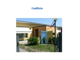
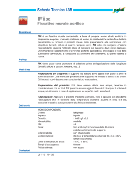
ISTRUZIONI PER IL MONTAGGIO DEL GRUPPO ANGOLO
ASSEMBLY INSTRUCTIONS FOR CORNER ARRANGEMENTS
1102
SEZIONE TIPO PER POSIZIONAMENTO
MONTANTE
TYPICAL CROSS-SECTION TO
POSITION THE POST
B
A
1.
2.
3.
1.
2.
3.
PARTICOLARE DELLE MISURE PER
FORO SUPERIORE SUL FIANCO
PARTICOLARE DELLE MISURE PER FORO
INFERIORE SUL FIANCO
DETAIL OF DIMENSIONS FOR
UPPER HOLE ON SIDE PANEL
DETAIL OF DIMENSIONS FOR LOWER
HOLE ON SIDE PANEL
Fissare i due montanti laterali alla base <1> posizionata a 45° rispetto all’angolo con viti ø 3.5 mm L. 40 mm autofilettanti con testa piana,
taglio a croce, rispettando le misure riportate nei due particolari <A> e <B>;
Allineare le basi della parete di destra <2> e di sinistra <3> ai due montanti installati alla base <1> a 45° e fissarli sempre con viti
autofilettanti ai fianchi delle basi stesse <1> e <2> come da particolari <A> e <B> accertandosi che le misure dell’angolo finito devono
corrispondere a 1050 mm nei due lati adiacenti al muro.
Proseguire con il montaggio dei rimanenti elementi della cucina
Fix the two side posts to the base unit <1> fitted at 45° to the corner using ø 3.5 mm self-tapping, flat, cross-headed screws, L. 40 mm, by
following the dimensions shown in the two details <A> and <B>;
Align the base units on the right <2> and left <3> sides to the two posts installed alongside base unit <1> at 45° and fix them using selftapping screws to the sides of the same base units <1> and <2> as shown in details <A> and <B>, making sure that the size of the
finished corner is 1050 mm on the two sides adjacent to the wall.
Proceed by installing the remaining kitchen elements.
ISTRUZIONI PER IL MONTAGGIO DEL GRUPPO ANGOLO
ASSEMBLY INSTRUCTIONS FOR CORNER ARRANGEMENTS
1102
VISTA RETRO
REAR VIEW
1.
2.
3.
1.
2.
3.
Fissare le fascette <A> alle basi <D2> per mezzo delle viti <E> facendo riferimento ai fori di giunzione dei
fianchi.
Posizionare il supporto <B> in linea con la parte superiore delle fascette <A> (verificare con bolla), quindi
fissare al muro tramite fischer.
Appoggiare il piano cottura <C> sopra le fascette <A> e il supporto <B>.
Fix the fascias <A> to the base units <D2> by means of the screws <E> and using the jointing holes on the
sides as references.
Place the support <B> so that it is in line with the top part of the fascia <A> (use a spirit level to check
alignment), then fix it to the wall using Fischer screw plugs.
Place the hob <C> on the fascias <A> and the support <B>.
Scaricare