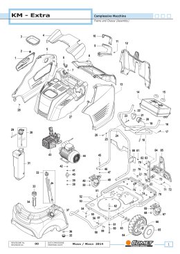
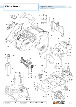
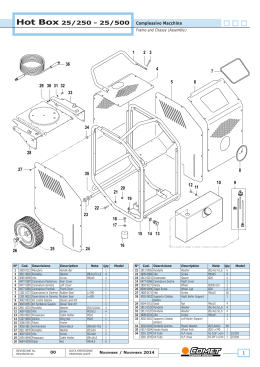
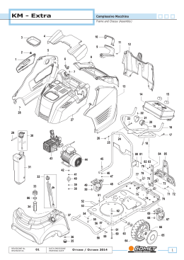
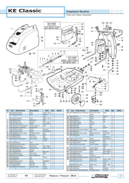
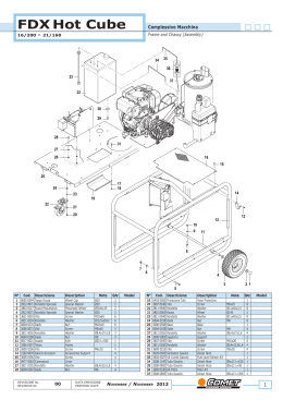
Hot Box 15/200
Complessivo Macchina


Frame and Chassy (Assembly)
6
5
12
11
7
4
13
10
8
3
14
9
15
17
16
23
2
22
1
21
27
18
28
29
26
19
24
25
20
59 58
30
31
61 60
62
69
68
70
33
34
67
65 64
71
72
54
73
74
51
50
38
39 40
80
41
DATA EMISSIONE
PRINTING DATE
55 56
53
52
37
00
57
66
35
36
REVISIONE Nr.
REVISION Nr.
63
42
43
44
Novembre / November 2014
49
48
45
47
46
1
Hot Box 15/200
N°
1
2
3
4
5
6
7
8
9
10
11
12
13
14
15
16
17
18
Cod.
Descrizione
Vite
Rondella
Sportello per Ispezione
Vite Speciale
Protezione Camino
Coperchio
Carenatura Destra
Supporto Lancia
Vite
Carenatura Superiore
Maniglia Inferiore
Maniglia Superiore
Vite
Carenatura Posteriore
Carenatura Sinistra
Kit Quadro Elettrico
Manopola
Supporto Quadro
Elettrico
19 3605 0164 Vite
20 3605 0167 Vite
21 3002 0776 Supporto Manometro
22
23
24
25
26
27
28
29
30
31
32
33
34
35
36
37
38
39
40
41
42
43
44
45
46
47
48
49
50
51
52
Description
Note
Q.ty
15
15
1
1
1
1
1
2
1
1
2
2
4
1
1
1
2
1
3605 0114
2812 0135
0402 0476
1407 0051
2416 0309
0402 0477
0477 0351
1202 0079
3620 0003
0477 0352
1818 0047
1818 0048
3625 0095
0477 0348
0477 0350
2610 0418
1817 0081
1803 0108
Screw
Washer
Inspection door
Special Cover Screw
Boiler Protection
Lid
Right Cover
Lance Support
Screw
Upper Cover
Lower Handle
Top Handle
Scew
Rear Cover
Left Cover
Electric Panel Kit
Knob
Electric Panel Support
5x16
Ø4,5x11x1
M6x35
5x35
1
4
1
3625 0095
3202 0427
1803 0109
2811 0125
0604 0011
0477 0349
3042 0029
3200 0038
1209 0088
1002 0113
3029 0036
1209 0140
3200 0073
0017 0020
3206 0335
2811 0097
3607 0097
0604 0011
2811 0125
1803 0107
3605 0164
0604 0177
3607 0183
2812 0070
2810 0100
0402 0478
0009 0179
2810 0067
3607 0242
2811 0108
2000 0067
Screw
Screw
Pressure Gauge
Bracket
Screw
Plug
Fan Support
Washer
Nut
Main Cover
Dielel Level Kit
Diesel Plug
Gasket
Diesel Filter
Diesel Tank Kit
Gasket
Plug
Wheel Axle
Frame
Washer
Screw
Nut
Washer
Front Bumper
Screw
Nut
Screw
Washer
Wheel
Wheel Cover
Ring
Wheel
Screw
Washer
Reduction
4,2x13
Ø51
2
1
1
2
2
1
1
1
1
1
1
1
1
1
1
3
3
4
4
1
4
1
1
4
2
2
2
1
4
4
1
Vite
Tappo
Supporto Ventilatore
Rondella
Dado
Carenatura Principale
Kit Livello Gasolio
Tappo Gasolio
Guarnizione
Filtro Gasolio
Kit Serbatoio Gasolio
Guarnizione
Tappo
Assale Ruota
Telaio
Rondella
Vite
Dado
Rondella
Paraurti Frontale
Vite
Dado
Vite
Rondella
Ruota
Copriruota
Anello
Ruota
Vite
Rondella
Riduzione
53 1209 0114 Rondella
54 1407 0040 Nipplo
Washer
Nipple
55
56
57
58
59
60
61
62
Washer
Screw
Cable Holder
Bottom Cover
Support Plate
Washer
Nut
Screw
2811 0125
3607 0097
2434 0022
0477 0357
3002 0772
2811 0125
0604 0011
3605 0103
2
Rondella
Vite
Pressacavo
Carena Inferiore
Piastra Supporto
Rondella
Dado
Vite
M6x20
4,2x13
MNF
Ø6,4x12x1,6
M6
Ø34x48x2
G3/4" F
Ø6,5x18x1,5
M6x16
M6
Ø6,4x12x,16
M6x35
M10
M10x80
Ø20
Ø260
Ø100
M8x16
Ø8,5x15x1,6
M-F G1/23/8"
G1/2"
F-F
M22x1,5-G1/2"
Ø6,4x12x1,6
M6x16
PG16
Ø6,4x12x1,6
M6
4x20
Complessivo Macchina


Frame and Chassy (Assembly)
Model
N°
Cod.
Descrizione
Description
63 1227 0002 Ghiera per Pressacavo Ring Nut for Cable
Holder
64 2803 0256 Raccordo
Coupling
65 1209 0091 Rondella
66 2803 0626 Raccordo
Washer
Coupling
67
68
69
70
71
72
73
74
80
Nut
Washer
Screw
Rotating Wheel
Washer
Screw
Screw
Screw
H.P. Hose
0604 0011
2811 0125
3605 0164
2810 0110
2811 0108
3607 0242
3625 0095
3622 0011
3301 1374
Dado
Rondella
Vite
Ruota Girevole
Rondella
Vite
Vite
Vite
Kit Tubo
Note
PG16
M-F
M22x1,5-G3/8"
G3/8"
M-M G3/8"M18x1,5
M6
Ø6,4x12x1,6
M6x35
Ø100
Ø8,5x15x1,6
M8x16
4,2x13
M8x10
R2 5/16"
L=2m
Q.ty
1
Model
1
1
1
4
4
4
1
4
4
1
1
1
1
1
1
1
1
1
1
1
1
4
REVISIONE Nr.
REVISION Nr.
00
DATA EMISSIONE
PRINTING DATE
Novembre / November 2014
Hot Box 15/200
Quadro Elettrico
Electrical Panel
1
N°
34
2
33
35
3
4
SCHEMA ELETTRICO
WIRING DIAGRAM
M
3
4
6
5
14
Rosso
PT
(Red)
Marrone
32
(Brown)
R
P
t
K1
(Red)
A2
Blu (Bleu)
I
Marrone
Rosso
A1
DENOMINAZIONE
PV
(Brown)
4
5
1
2
DESCRIPTION
M
Motore pompa
Pump motor
K
K1
I
R
PT
PV
Termica motore
Teleruttore
Bobina teleruttore
Interruttore 0-1
Rele' stop totale
Pressostato testata
Pressostato valvola
Motor thermic device
Remote control switch
Remote control switch coil
Switch 0-1
Automatic delayed stop relay
Head pressure switch
Valve pressure switch
t
ATTENZIONE:
P=
Pressione ( Pressure.)
WARNING:
5
Le riparazioni devono
essere eseguite SOLO da
personale qualificato !!
Repairs by qualified
personnel only !!
COLLEGAMENTO
CONNECTION DIAGRAM
Motore
Motor
U
V
W
Teleruttore
Remote control switch
Description
Cover
Gasket
Electronic Board
Screw
Fuse
Bushing-Seal
Potentiometer Plate
Boiler Potentiometer
End Wire Connector
Wire Connector
Wire Connector
Wire Connector
Wire Connector
Wire Connector
L.T. Transformer
18 1012 0003 Fusibile
Fuse
19 3001 0550 Scatola Elettrica
20 3226 0087 Trasformatore A.T.
Electrical Box
H.T. Trasformer
2
21 0456 0411 Cavo Trasformatore
A.T.
22 3609 0199 Vite
23 0456 0309 Cavo Alimentazione
H.T. Trasformer Cable
24
25
26
27
28
29
30
31
32
33
34
35
Screw
Washer
Nut
Spring Washer
Cable Holder
Thermic Relay
Switch
Bushing-Seal
Electric Diagram
Screw
Screw
Screw
A1
4
3
5 13
6 14
Rele' stop
totale
31
A2
Automatic delayed stop relay
V
Pressostato valvola
Valve pressure switch
W
1
4
2
5
Interruttore 0-1
Switch 0-1
Pressostato
testata
Head pressure
switch
8
T S R
30
6
7
9
10
29
11
12
13
14
15
16
17
3607 0234
2811 0037
0604 0061
2819 0009
2434 0052
2821 0040
1410 0085
0204 0041
1610 1590
3605 0103
3623 0007
3623 0007
Vite
Rondella
Dado
Rondella Elastica
Pressacavo Cavo Elettr.
Relé Termico
Interruttore
Boccola
Schema Elettrico
Vite
Vite
Vite
Note
Knob
Electrical Panel Sticker
1
Termica motore
Overload motor
Motore
Motor
U
Descrizione
Blu (Bleu)
P
13
K
RIF.
Cod.
1 1817 0081 Manopola
2 0457 0057 Etichetta Quadro
Elettrico
3 0402 0461 Coperchio
4 1201 0240 Guarnizione
5 3043 0049 Scheda Elettrica
6 3625 0031 Vite
7 1012 0031 Fusibile
8 0204 0064 Boccola
9 2404 0176 Staffa Potenziometro
10 2441 0004 Potenziometro Caldaia
11 1805 0055 Morsetto Chiusura
12 1805 0054 Morsetto
13 1805 0052 Morsetto
14 1805 0052 Morsetto
15 1805 0053 Morsetto
16 1805 0053 Morsetto
17 3226 0084 Trasformatore B.T.
R
S
T
1
2
3~

Screw
Electrical Cable
Ø4 L=1080
3,5x9,5
5x20F 1,6A
Blu / Blue
230400V/24V
5x20F 2A
250V
230V
50/60Hz
M5x40
3Gx2,5mm²
L=6900
M5x30
Ø5,3x10x1
M5x5
M20x1,5
24Vac
4x20
M4x10
M4x10
Q.ty
2
1
Model
1
1
1
4
1
1
1
1
1
1
1
1
1
1
1
1
1
1
1
2
1
1
1
3
2
1
2
1
1
1
4
2
2
18
19
28
26
27
20
25
22
24
21
23
REVISIONE Nr.
REVISION Nr.
00
DATA EMISSIONE
PRINTING DATE
Novembre / November 2014
3
Hot Box 15/200
2
Caldaia

Boiler
77
1
3
4
95
76
78
88 87 86
79
74
73
75
5
82
92
6
67
70
66
71
84
83
81
69
72
85
80
68
64
63
89
90
91
62
60
58 59
57
55 56
54
65
61
53
52
7
49
8
9
10
11
50
51
43
42
45
48
47
44
46
12
38
14
15
16
17
18
19 20
23
24
27
28
41
37
25
T
OU 22
21
13
39
40
29
30
IN
33
32
31
34
35
36
26
4
REVISIONE Nr.
REVISION Nr.
00
DATA EMISSIONE
PRINTING DATE
Novembre / November 2014
Hot Box 15/200
N°
Cod.
1
2
3
4
5
6
7
3605 0150
0218 0017
3625 0095
0402 0454
0402 0453
0424 0491
2404 0189
Descrizione
8
9
10
11
12
13
14
15
16
17
18
2811 0097
3607 0098
0424 0490
3044 0022
2822 0017
0009 0245
1210 0712
1227 0035
3228 0022
1209 0078
2825 0021
Screw
Air Nozzle
Screw
Upper Cover
Lower Covert
Boiler Body
Boiler Mounting
Bracket
Rondella
Washer
Vite
Screw
Corpo Caldaia Interno Internal Boiler Body
Serpentina
Coil
Refrattario
Refractory Pad
Corpo Inferiore
Bottom Body
Guarnizione Caldaia
Boiler Gasket
Ghiera Fiss. Serpentina Coil-Lock Nut
Sensore Termostato
Thermostat Feeler
Rondella
Washer
Riduzione
Reduction
Description
19
20
21
22
1209 0097
0424 0377
1209 0113
0011 0006
Rondella
Raccordo
Rondella
Adattatore
Vite
Boccaglio
Vite
Coperchio Superiore
Coperchio Inferiore
Corpo Caldaia
Piedi Caldaia
Washer
Coupling
Washer
Adapter
23 1209 0091 Rondella
24 2803 0644 Raccordo Speciale
Washer
Special Nipple
25
26
27
28
29
30
31
32
33
34
35
36
3208 1172
3208 1242
3200 0080
2421 0017
0011 0003
1209 0091
0600 0005
2811 0010
1215 0275
1209 0091
0011 0003
2803 3427
Tubo
Tubo
Tappo
Flussostato
Adattatore
Rondella
Dado
Rondella
Kit Valvola Sicurezza
Rondella
Adattatore
Raccordo "T"
Hose
Hose
Plug
Flow Switch
Adapter
Washer
Nut
Washer
Safety Valve Kit
Washer
Adapter
"T" Coupling
37
38
39
40
41
42
1209 0113
2421 0040
1209 0091
2000 0041
3208 1096
2803 3427
Rondella
Pressostato
Rondella
Nipplo
Tubo
Raccordo "T"
Washer
Pressure Switch
Washer
Nipple
Hose
"T" Coupling
43 1209 0113 Rondella
44 2421 0038 Pressostato
45 2000 0067 Riduzione
Washer
Pressure Switch
Reduction
46 1810 0041 Manicotto
47 0466 0052 Coperchio
Convogliatore
48 0466 0026 Farfalla Aria
49 3632 0093 Kit Ventola
50 0404 0031 Convogliatore
51 3625 0028 Vite
52 2811 0006 Rondella
53 3625 0049 Vite
54 3608 0005 Vite
55 1831 0555 Motore Elettrico
56 3609 0123 Vite
57 3622 0029 Vite
58 1211 0015 Raccordo Curvo
59 3200 0017 Tappo
60 2803 0570 Raccordo p.g.
61 0217 0012 Bobina
62 1221 0017 Giunto
63 0430 0057 Connettore
64 2803 0322 Raccordo
65 2422 0011 Pompa Gasolio
66 3208 1268 Tubo Gasolio
67 1002 0120 Filtro Gasolio
68 3208 0938 Tubo Gasolio
69 3208 0893 Tubo Gasolio
70 3042 0024 Kit Livello Gasolio
Sleeve
Conveyor Cover
REVISIONE Nr.
REVISION Nr.
00
Fly Valve
Fan Kit
Conveyor
Screw
Washer
Screw
Screw
Electric Motor
Screw
Screw
Elbow Coupling
Cap
Coupling
Coil
Coupling
Connector
Coupling
Diesel Pump
Diesel Hose
Diesel Filter
Diesel Hose
Diesel Hose
Fuel Level Sensor Kit
Note
Q.ty
3
1
3
1
1
1
4
4,2x13
4,2x13
Ø6,5x18x1,5
M6x20
Ø286x283
Ø6,99x291,5
G3/8"x8
G1/8"
M-F
G1/4"-G1/8"
1/4"
G1/4"F
G1/4"
M-F G1/43/8"
G3/8"
G3/8"M18x1,5
Ø9x12
5/16" L=140
GC1/4"x10
M-M G3/8"
M-F G3/8"
G3/8"
G1/4"
Ø15x28
G3/8"
M-F G3/8"
M-F-F 3/83/8-1/4"
G1/4"
G1/4" 30bar
G3/8"
G3/8"
5/16" L=410
M-F-F 3/83/8-1/4"
G1/4"
G1/4" 15bar
M-F G1/23/8"
4
4
1
1
1
1
1
2
1
1
1
1
1
1
1
1
1
Caldaia

Boiler
Model
N°
Cod.
71
72
73
74
3208 1201
1202 0078
3208 1202
3002 0768
75
76
77
78
79
80
81
82
83
84
85
86
87
88
89
90
1202 0052
0535 0073
3208 1169
0600 0076
0204 0097
0602 0079
3400 0650
0466 0056
3019 0035
3200 0074
2819 0034
3623 0042
0805 0032
2427 0004
3625 0019
0424 0364
91 1209 0102
92 2828 0016
95 0335 0042
Descrizione
Description
Tubo Aspirazione
Gancio per Tubi
Tubo Mandata
Supporto Livello
Gasolio
Gancio
Kit Cavi A.T.
Tubo Gasolio in Rame
Raccordo
Ogiva
Disco Porta Elettrodi
Ugello Gasolio
Disco Turbolenza Aria
Seeger Esterno
Tappo
Rondella
Vite
Elettrodo Bifilare
Porta Ugello
Vite
Corpo Porta
Fotoresistenza
Rondella
Fotoresistenza
Kit Bruciatore
Suction Hose
Tubes Hook
Delivery Hose
Diesel Level Support
Hook
H.T. Cable Kit
Copper Diesel Hose
Coupling
Ogive
Elettrodi Holder Disc
Diesel Nozzle
Air Turbolence Ring
Outer Seeger
Plug
Washer
Screw
Bifilar Electrode
Nozzle Holder
Screw
Photoresistor Body
Washer
Photoresistor
Complete Burner Kit
Note
Ø4x6
Ø4x6
L=530
Ø4
M8x1
1,35 - 60°B
ZJ Ø22
Ø21,75x2
Ø5,3x11x05
M5x16
M4x12
Ø15x24x2
Q.ty
1
2
1
1
Model
1
1
1
1
1
1
1
1
1
1
1
1
1
1
2
1
1
1
1
1
1
1
1
1
1
1
1
1
1
1
1
1
1
1
1
1
1
1
1
1
1
1
1
1
1
3,5x25
5
Ø4,3x9
1
3,5x9,5
1
M4x10
4
1
M5x14
3
M5x10
3
M-F G1/8"
1
G1/8"x8
1
G1/4"
2
1
1
1
G1/8"
1
1
Ø6x12 L=460 1
15 μm
1
Ø6x12 L=270 1
Ø6x12 L=650 1
1
Ø200x45
DATA EMISSIONE
PRINTING DATE
Novembre / November 2014
5
Scaricare