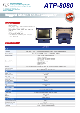
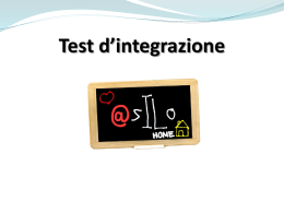
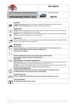
CarAlarm
TIPO DI AUTOVETTURA ED ANNO DI PRODUZIONE
HYUNDAI I20 2009
SCHEDA NUMERO
14.36
LOCATION OF THE CAR ALARM CONTROL UNIT
Compact control units and sirens: place in the bonnet passenger side near the box of refreshing fluid.
Modular control units and accessories: place under the dashboard driver side at left of fuse box.
--------------------------------------------------------------------------------------------------------------------------------------------CAR ALARM SUPPLY
Positive: Connect at Red wire in the White 12-pin connector sigled “E” in the fuse box driver side. (see image 1)
Negative: Connect to the manufacturer’s original setting in the lateral part of driver side.
--------------------------------------------------------------------------------------------------------------------------------------------IMMOBILISER
Cut the White wire in the Blue/White 6-pin connector under the steering-wheel near the block key.
--------------------------------------------------------------------------------------------------------------------------------------------POSITIVE IGNITION KEY (+15)
Connect at Pink wire in the White 12-pin connector sigled “E” in the fuse box driver side. (see image 1)
--------------------------------------------------------------------------------------------------------------------------------------------CENTRAL DOOR LOCKING (Connection with RF remote controlled alarm)
Control of interruption for closing: For closing cut the Blue/Black (pos.6)wire of White 24-pin connector,in the
Black central at 3 connector place under the dashboard driver side near the steering-column. For opening connect on the
Blue/Black (pos. n°6)wire at door driver side. (see scheme of central door locking)
-------------------------------------------------------------------------------------------------------------------------------------------ARMING OF PASSIVE TYPE ALARM (Connection with alarm armed by vehicle’s original remote control)
Follow the method of connections in INSTALLATION FILE 14.36.1
-------------------------------------------------------------------------------------------------------------------------------------------DIRECTION INDICATORS
Connect at Blue and Green wire in the White 12-pin connector sigled “E” in the fuse box driver side. (see image 1)
------------------------------------------------------------------------------------------------------------------------------------------DOOR AND BOOT PROTECTION
Connect at Green (front and rear doors) and Green (boot) wire in the White 24-pin connector in the central unit control
at 3 connector under the steering-column. (see image 2)
--------------------------------------------------------------------------------------------------------------------------------------------BONNET PROTECTION
Bonnet : Fit the switch provided.
--------------------------------------------------------------------------------------------------------------------------------------------------
Scheme of central door locking
02/02/2009 rev.00Le informazioni riportate su questa scheda sono da considerarsi indicative e da verificarsi prima di eseguire ogni collegamento in quanto
il costruttore puo,’ in qualsiasi momento , introdurre modifiche. In ogni caso la MetaSystem declina ogni responsabilità per eventuali danni arrecati alla
vettura da un montaggio errato.
CarAlarm
TIPO DI AUTOVETTURA ED ANNO DI PRODUZIONE
HYUNDAI I20 2009
SCHEDA NUMERO
14.36.1
FITTIN INSTRUCTIONS OF TOP PLIP / MULTI PLIP ALARM
After completing connections, set the control unit for “HY” type controls (see LINKING
UP THE VEHICLE CAN in the fitting instructions for details of this procedure) or use the
Car Alarm Programmer.
FUNCTION
COLOUR CABLE ALARM
COLOUR CABLE CAR
Arming Control
RED/BLACK
YELLOW/BLUE
GREEN/BLACK
Disarming Control
RED/WHITE
GREEN/BLUE
BLUE/BLACK
Inhibition
LIGHT BLUE/YELLOW
WHITE/BLUE
GREEN
(doors protection)
Inhibition
RED/YELLOW
RED/YELLOW
Not connect
POSITIONING ON THE CAR
White 24-pin connector
in the central control
unit at 3 connector
under the steeringcolumn. (see image 2)
White 24-pin connector
in the central control
unit at 3 connector
under
the
steering
column. (see image 2)
Function Note:
In the car with a 3 push-button remote control (with boot unlock)is necessary before
make the disarming with a push-button of unlock and after opening boot.
Image 1
Image 2
02/02/2009 rev.00Le informazioni riportate su questa scheda sono da considerarsi indicative e da verificarsi prima di eseguire ogni collegamento in quanto
il costruttore puo,’ in qualsiasi momento , introdurre modifiche. In ogni caso la MetaSystem declina ogni responsabilità per eventuali danni arrecati alla
vettura da un montaggio errato.
Scaricare