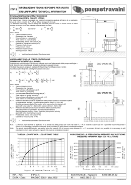
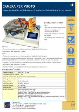
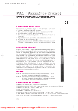
I D F GB E NL Abbinamento bruciatore - rampa gas Verbindung Brenner - Gasstrecke Accouplement brûleur - rampe gaz Burner combined with gas train Combinación quemador - rampa de gas Combinatie brander - gasstraat MODELLO - MODELL - MODÈLE MODEL - MODELO RLS 500-650-800/M MX RLS 300-400-500-650-800/E MX RLS 300-400-500-650-800/EV MX 20043099 (7) - 04/2013 Abbinamento bruciatore - rampa gas 1 1.1 Abbinamento bruciatore - rampa gas Designazione rampa gas Serie: MB MBC DMV DMV12 VGD CB CBH MV CG Grandezza costruttiva: 405 407 65 507 20 120 505 15 10 Funzionamento: /S /1 /2 /P 410 120 510 32 220 412 300 512 40 415 700 - 420 1200 520 50 T SD SM Campo pressione uscita standard: F SM 3 50125 125 50150 150 Terminali - Morsettiera Spina domestica Spina media potenza 0 2 3 4 5 6 8 15 Comando valvole: CT 5000 50100 100 R filettato F flangia standard ISO F1 flangia quadrata BS1 F2 flangia quadrata BS2 F3 flangia quadrata BS3 - BS4 Connessione elettrica: /1 3100 5080 80 0 CT controllo di tenuta a bordo rampa CQ con pressostato per controllo di tenuta Tipo giunzione: 5065 1900 5065 65 solo funzione ON-OFF apertura 1 gradino apertura 2 gradini apertura 1 gradino con regolatore proporzionale aria/gas Controllo di tenuta: CB 525 - senza regolatore di pressione con regolatore e pressione proporzionale aria/gas con regolatore e pressione uscita fino a 20 mbar con regolatore e pressione uscita fino a 30 mbar con regolatore e pressione uscita fino a 40 mbar con regolatore e pressione uscita fino a 50 mbar con regolatore e pressione uscita fino a 60 mbar con regolatore e pressione uscita fino a 80 mbar con regolatore e pressione uscitaf ino a 150 mbar 0 2 comune separato 0 DESIGNAZIONE BASE DESIGNAZIONE ESTESA 1 I 20043099 Abbinamento bruciatore - rampa gas 1.2 Rampa gas Rampa gas Codice Modello VPS Ø C.T. Adattatore Codice Codice RLS 300 RLS 400 RLS 500 RLS 650 RLS 800 3970250 MB 415/1 - RT 52 Rp 1” ½ 3010123 3000843 + 3000826 + 20064220 3970257 MB 420/1 - RT 52 Rp 2” 3010123 3000826 + 20042324 3970221 MBC 1200/1 - RSM 60 Rp 2” 3010367 3970225 MBC 1200/1 CT RSM 60 Rp 2” 3970222 MBC 1900/1 - FSM 40 DN 65 3970226 MBC 1900/1 CT FSM 40 DN 65 3970223 MBC 3100/1 - FSM 40 DN 80 3970227 MBC 3100/1 CT FSM 40 DN 80 3970224 MBC 5000/1 - FSM 80 DN 100 3970228 MBC 5000/1 CT FSM 80 DN 100 3970145 CB 512/1 - RSM 30 Rp 1” ½ 3970146 CB 520/1 - RSM 30 Rp 2” 3970160 CB 520/1 CT RSM 30 Rp 2” 20044659 CB 525/1 - RSM 30 Rp 2” 20044660 CB 525/1 CT RSM 30 Rp 2” 3970147 CB 5065/1 - FSM 30 DN 65 3970161 CB 5065/1 CT FSM 30 DN 65 3970148 CB 5080/1 - FSM 30 DN 80 3970162 CB 5080/1 CT FSM 30 DN 80 3970149 CB 50100/1 - FSM 30 DN 100 3970163 CB 50100/1 CT FSM 30 DN 100 3010367 3010367 3010367 - 3010221 - 3010369 3010222 (1) 3010223 - 3010370 3010367 3000843 + 3000826 + 20064220 3010367 3010367 3010367 3010367 3010367 - 20015871 CB 50125/1 - FSM 30 DN 125 3970196 DN 125 - 20043035 DMV 512/1 - RSM -0 Rp 1” ½ 3010367 20043037 DMV 512/1 CQ RSM -2 Rp 1” ½ 20043038 DMV 520/1 - RSM -0 Rp 2” 3010367 20043039 DMV 520/1 CT RSM -0 Rp 2” 20043040 DMV 520/1 CQ RSM -2 Rp 2” 20043053 DMV 525/1 - RSM -0 Rp 2” 3010367 20043054 DMV 525/1 CT RSM -0 Rp 2” 20043055 DMV 525/1 CQ RSM -2 Rp 2” 20043041 DMV 5065/1 - FSM -0 DN 65 3010367 20043042 DMV 5065/1 CT FSM -0 DN 65 20043043 DMV 5065/1 CQ FSM -2 DN 65 20043044 DMV 5080/1 - FSM -0 DN 80 3010367 20043045 DMV 5080/1 CT FSM -0 DN 80 20043046 DMV 5080/1 CQ FSM -2 DN 80 20043047 DMV 50100/1 - FSM -0 DN 100 3010367 20043048 DMV 50100/1 CT FSM -0 DN 100 20043049 DMV 50100/1 CQ FSM -2 DN 100 20043050 DMV 50125/1 - FSM -0 DN 125 3010367 20043051 DMV 50125/1 CT FSM -0 DN 125 20043052 DMV 50125/1 CQ FSM -2 DN 125 CB 501251 CT FSM 30 3000826 + 20042324 3010367 3000826 + 20042324 3000826 + 20042324 3010221 - 3010369 3010222 (1) 3010223 - 3010370 3010224 3000843 + 3000826 + 20064220 3000826 + 20042324 3000826 + 20042324 3010221 - 3010369 3010222 (1) 3010223 - 3010370 3010224 Tab. A 20043099 2 I Abbinamento bruciatore - rampa gas 1.2.1 Rampa gas: codice specifico per collegamento a destra Rampa gas Codice Modello VPS Ø C.T. Adattatore Codice Codice 20069032 DMV 512/1 CQ RSM -2 Rp 1” ½ 20069136 DMV 520/1 CT RSM -0 Rp 2” 20068703 DMV 520/1 CQ RSM -2 Rp 2” 20069144 DMV 5065/1 CT FSM -0 DN 65 20069145 DMV 5065/1 CQ FSM -2 DN 65 20069148 DMV 5080/1 CT FSM -0 DN 80 20069149 DMV 5080/1 CQ FSM -2 DN 80 20069150 DMV 50100/1 CT FSM -0 DN 100 20069151 DMV 50100/1 CQ FSM -2 DN 100 20069152 DMV 50125/1 CT FSM -0 DN 125 20069153 DMV 50125/1 CQ FSM -2 DN 125 solo per RLS 300 3000843 + 3000826 + 20064220 3000826 + 20042324 3010221 - 3010369 3010222 (1) 3010223 - 3010370 3010224 Tab. B Legenda (Tab. A - Tab. B) C.T. 1.3 Dispositivo controllo tenuta valvole gas: rampa priva del dispositivo di controllo tenuta; dispositivo che può essere ordinato a parte, vedi colonna VPS, ed installato successivamente. rampa con il dispositivo di controllo tenuta installato. VPS Dispositivo di controllo tenuta valvole. Fornito su richiesta separatamente dalla rampa gas. Non disponibile (1) Da utilizzare se necessario per distanziare la rampa gas dal bruciatore. Adattatore Codice Adattatore Lunghezza (mm) 3000826 300 3000843 35 3010369 3010370 10 50 20042324 20064220 65 3010221 3010222 3010223 3010224 400 400 400 320 3 I 20043099 Abbinamento bruciatore - rampa gas 1.4 Molla per regolatore di pressione Per variare il campo di pressione del regolatore della rampa gas sono disponibili i modelli di molla sotto riportati. Molla Rampa gas Colore MBC 1900/1* - 3100/1* MBC 5000/1* Campo di pressione Codice Bianco 4 - 20 mbar 3010381 Rosso 20 - 40 mbar 3010382 Nero 40 - 80 mbar 3010383 Verde 80 - 150 mbar 3010384 CB 512/1* DMV 512/1* Rosso 25 - 55 mbar 3010131 Nero 60 - 110 mbar 3010157 Rosa 90 - 150 mbar 3090486 CB 520/1* - 525/1* DMV 520/1* - 525/1* Rosso 25 - 55 mbar 3010132 Nero 60 - 110 mbar 3010158 Rosa 90 - 150 mbar 3090487 Rosso 25 - 55 mbar 3010133 Nero 60 - 110 mbar 3010135 Rosa 100 - 150 mbar 3090456 Grigio 140 - 200 mbar 3090992 Rosso 25 - 55 mbar 3010134 Nero 60 - 110 mbar 3010136 CB 5065/1* - 5080/1* DMV 5065/1* - 5080/1* CB 50100/1 * DMV 50100/1 * CB 50125/1* DMV 50125/1* Rosa 100 - 150 mbar 3090489 Grigio 140 - 200 mbar 3092174 Rosso 25 - 55 mbar 3010315 Giallo 30 - 70 mbar 3010316 Nero 60 - 110 mbar 3010317 Rosa 100 - 150 mbar 3010318 Tab. C * Con e senza controllo di tenuta 1.5 Diagrammi perdite di carico I diagrammi indicano le perdite di pressione minima del bruciatore in abbinamento con le rampe gas con utilizzo di gas naturale G20 e G25. I valori sono misurati alla presa di pressione gas della testa di combustione (vedi manuale d’istruzione del bruciatore). A questi valori aggiungere la pressione della camera di combustione; i valori così calcolati rappresentano la pressione minima di ingresso alla rampa. Per valori di pressione differenti da quelli indicati contattare il Servizio Tecnico. ATTENZIONE I valori riportati si riferiscono a: – gas naturale G 20 - PCI 9,45 kWh/Sm3 (8,2 Mcal/Sm3) – gas naturale G 25 - PCI 8,13 kWh/Sm3 (7,0 Mcal/Sm3) 20043099 4 I Verbindung Brenner - Gasstrecke 1 1.1 Verbindung Brenner - Gasstrecke Bezeichnung Gasstrecke MB MBC DMV DMV12 VGD CB CBH MV CG Serie : Baugröße: 405 10 407 65 507 20 120 505 15 Betrieb: /S /1 /2 /P 410 120 510 32 220 412 300 512 40 415 700 - T SD SM Druckbereich Standard-Ausgang: F SM 3 5000 50100 100 50125 125 50150 150 Klemmen - Klemmenbrett Haushaltsstecker Mittelleistungsstecker 0 2 3 4 5 6 8 15 Ventilsteuerung: CT 3100 5080 80 R mit Gewinde F Flansch ISO-Standard F1 quadratischer Flansch BS1 F2 quadratischer Flansch BS2 F3 quadratischer Flansch BS3 - BS4 Elektrischer Anschluss: /1 1900 5065 65 0 CT Dichtheitskontrolle in Gasstrecke CQ mit Druckwächter zur Dichtheitskontrolle Verbindungstyp: 5065 525 - nur ON-OFF -Funktion Öffnung 1. Stufe Öffnung 2. Stufe Öffnung 1. Stufe mit proportionalem Luft-/Gasregler Dichtheitskontrolle: CB 420 1200 520 50 ohne Druckregler mit Regler und proportionalem Luft-/Gasdruck mit Regler und Ausgangsdruck bis 20 mbar mit Regler und Ausgangsdruck bis 30 mbar mit Regler und Ausgangsdruck bis 40 mbar mit Regler und Ausgangsdruck bis 50 mbar mit Regler und Ausgangsdruck bis 60 mbar mit Regler und Ausgangsdruck bis 80 mbar mit Regler und Ausgangsdruck bis 150 mbar 0 2 allgemein getrennt 0 BASISBEZEICHNUNG ERWEITERTE BEZEICHNUNG 1 D 20043099 Verbindung Brenner - Gasstrecke 1.2 Gasstrecke Gasstrecke Code Modell VPS Ø C.T. Code Adapter Code RLS 300 RLS 400 RLS 500 RLS 650 RLS 800 3970250 MB 415/1 - RT 52 Rp 1” ½ 3010123 3000843 + 3000826 + 20064220 3970257 MB 420/1 - RT 52 Rp 2” 3010123 3000826 + 20042324 3970221 MBC 1200/1 - RSM 60 Rp 2” 3010367 3970225 MBC 1200/1 CT RSM 60 Rp 2” 3970222 MBC 1900/1 - FSM 40 DN 65 3970226 MBC 1900/1 CT FSM 40 DN 65 3970223 MBC 3100/1 - FSM 40 DN 80 3970227 MBC 3100/1 CT FSM 40 DN 80 3970224 MBC 5000/1 - FSM 80 DN 100 3970228 MBC 5000/1 CT FSM 80 DN 100 3970145 CB 512/1 - RSM 30 Rp 1” ½ 3970146 CB 520/1 - RSM 30 Rp 2” 3970160 CB 520/1 CT RSM 30 Rp 2” 20044659 CB 525/1 - RSM 30 Rp 2” 20044660 CB 525/1 CT RSM 30 Rp 2” 3970147 CB 5065/1 - FSM 30 DN 65 3970161 CB 5065/1 CT FSM 30 DN 65 3970148 CB 5080/1 - FSM 30 DN 80 3970162 CB 5080/1 CT FSM 30 DN 80 3970149 CB 50100/1 - FSM 30 DN 100 3970163 CB 50100/1 CT FSM 30 DN 100 3010367 3010367 3010367 - 3010221 - 3010369 3010222 (1) 3010223 - 3010370 3010367 3000843 + 3000826 + 20064220 3010367 3010367 3010367 3010367 3010367 - 20015871 CB 50125/1 - FSM 30 DN 125 3970196 DN 125 - 20043035 DMV 512/1 - RSM -0 Rp 1” ½ 3010367 20043037 DMV 512/1 CQ RSM -2 Rp 1” ½ 20043038 DMV 520/1 - RSM -0 Rp 2” 3010367 20043039 DMV 520/1 CT RSM -0 Rp 2” 20043040 DMV 520/1 CQ RSM -2 Rp 2” 20043053 DMV 525/1 - RSM -0 Rp 2” 3010367 20043054 DMV 525/1 CT RSM -0 Rp 2” 20043055 DMV 525/1 CQ RSM -2 Rp 2” 20043041 DMV 5065/1 - FSM -0 DN 65 3010367 20043042 DMV 5065/1 CT FSM -0 DN 65 20043043 DMV 5065/1 CQ FSM -2 DN 65 20043044 DMV 5080/1 - FSM -0 DN 80 3010367 20043045 DMV 5080/1 CT FSM -0 DN 80 20043046 DMV 5080/1 CQ FSM -2 DN 80 20043047 DMV 50100/1 - FSM -0 DN 100 3010367 20043048 DMV 50100/1 CT FSM -0 DN 100 20043049 DMV 50100/1 CQ FSM -2 DN 100 20043050 DMV 50125/1 - FSM -0 DN 125 3010367 20043051 DMV 50125/1 CT FSM -0 DN 125 20043052 DMV 50125/1 CQ FSM -2 DN 125 CB 501251 CT FSM 30 3000826 + 20042324 3010367 3000826 + 20042324 3000826 + 20042324 3010221 - 3010369 3010222 (1) 3010223 - 3010370 3010224 3000843 + 3000826 + 20064220 3000826 + 20042324 3000826 + 20042324 3010221 - 3010369 3010222 (1) 3010223 - 3010370 3010224 Tab. A 20043099 2 D Verbindung Brenner - Gasstrecke 1.2.1 Gasstrecke: spezifischer Code für rechtsseitigen Anschluss Gasstrecke Code Modell VPS Ø C.T. Code Code 20069032 DMV 512/1 CQ RSM -2 Rp 1” ½ 20069136 DMV 520/1 CT RSM -0 Rp 2” 20068703 DMV 520/1 CQ RSM -2 Rp 2” 20069144 DMV 5065/1 CT FSM -0 DN 65 20069145 DMV 5065/1 CQ FSM -2 DN 65 20069148 DMV 5080/1 CT FSM -0 DN 80 20069149 DMV 5080/1 CQ FSM -2 DN 80 20069150 DMV 50100/1 CT FSM -0 DN 100 20069151 DMV 50100/1 CQ FSM -2 DN 100 20069152 DMV 50125/1 CT FSM -0 DN 125 20069153 DMV 50125/1 CQ FSM -2 DN 125 Zeichenerklärung (Tab. A - Tab. B) C.T. Dichtheitskontrolleinrichtung für Gasventile Gasstrecke ohne Dichtheitskontrolleinrichtung; Vorrichtung, die separat bestellt, siehe Spalte VPS, und nachträglich installiert werden kann. Gasstrecke mit installierter Dichtheitskontrolleinrichtung. 1.3 Adapter nur für RLS 300 3000843 + 3000826 + 20064220 3000826 + 20042324 3010221 - 3010369 3010222 (1) 3010223 - 3010370 3010224 VPS Tab. B Dichtheitskontrolleinrichtung der Gasventile. Auf Anfrage gesondert von der Gasstrecke lieferbar. Nicht verfügbar (1) Gegebenenfalls zu verwenden, um die Gasarmatur vom Brenner fernzuhalten. Adapter Code Adapter Länge (mm) 3000826 300 3000843 35 3010369 3010370 10 50 20042324 20064220 65 3010221 3010222 3010223 3010224 400 400 400 320 3 D 20043099 Verbindung Brenner - Gasstrecke 1.4 Feder für Druckregler Für die Änderung des Druckbereichs des Reglers der Gasstrekke sind nachstehende Federmodelle verfügbar. Feder Gasstrecke Farbe MBC 1900/1* - 3100/1* MBC 5000/1* CB 512/1* DMV 512/1* CB 520/1* - 525/1* DMV 520/1* - 525/1* CB 5065/1* - 5080/1* DMV 5065/1* - 5080/1* CB 50100/1 * DMV 50100/1 * CB 50125/1* DMV 50125/1* Druckbereich Code Weiß 4 - 20 mbar 3010381 Rot 20 - 40 mbar 3010382 Schwarz 40 - 80 mbar 3010383 Grün 80 - 150 mbar 3010384 Rot 25 - 55 mbar 3010131 Schwarz 60 - 110 mbar 3010157 Rosa 90 - 150 mbar 3090486 Rot 25 - 55 mbar 3010132 Schwarz 60 - 110 mbar 3010158 Rosa 90 - 150 mbar 3090487 Rot 25 - 55 mbar 3010133 Schwarz 60 - 110 mbar 3010135 Rosa 100 - 150 mbar 3090456 Grau 140 - 200 mbar 3090992 Rot 25 - 55 mbar 3010134 Schwarz 60 - 110 mbar 3010136 Rosa 100 - 150 mbar 3090489 Grau 140 - 200 mbar 3092174 Rot 25 - 55 mbar 3010315 Gelb 30 - 70 mbar 3010316 Schwarz 60 - 110 mbar 3010317 Rosa 100 - 150 mbar 3010318 Tab. C * Mit und ohne Dichtheitskontrolle 1.5 Lastverlust-Diagramme Die Diagramme geben die Verluste des Mindestdrucks des Brenners in Verbindung mit Gasstrecken bei Verwendung von Erdgas G20 und G25. Die Werte werden am Gasdruckanschluss des Flammkopfs gemessen (siehe Betriebsanleitung des Brenners). Diesen Werten muss der Druckwert der Brennkammer zugerechnet werden. Die sich daraus errechnenden Werte stellen den Mindestdruck am Eingang der Gasstrecke dar. ACHTUNG Bei Druckwerten, die von den angegebenen abweichen, nehmen Sie bitte Kontakt mit dem Technischen Kundendienst auf. Die Werte beziehen sich auf: – Erdgas G 20 - PCI 9,45 kWh/Sm3 (8,2 Mcal/Sm3) – Erdgas G 25 - PCI 8,13 kWh/Sm3 (7,0 Mcal/Sm3) 20043099 4 D Accouplement brûleur - rampe gaz 1 1.1 Accouplement brûleur - rampe gaz Désignation rampe gaz MB MBC DMV DMV12 VGD CB CBH MV CG Série : Dimension : 405 407 65 507 20 120 505 15 10 Fonctionnement : /S /1 /2 /P 410 120 510 32 220 412 300 512 40 415 700 - 420 1200 520 50 T SD SM Plage de pression sortie standard : F SM 3 50125 125 50150 150 Bornes - Bornier Prise de courant domestique Prise moyenne puissance 0 2 3 4 5 6 8 15 sans régulateur de pression avec régulateur et pression proportionnelle air/gaz avec régulateur et pression sortie jusqu'à 20 mbars avec régulateur et pression sortie jusqu'à 30 mbars avec régulateur et pression sortie jusqu'à 40 mbars avec régulateur et pression sortie jusqu'à 50 mbars avec régulateur et pression sortie jusqu'à 60 mbars avec régulateur et pression sortie jusqu'à 80 mbars avec régulateur et pression sortie jusqu'à 150 mbars Commande vannes : CT 5000 50100 100 R fileté F bride standard ISO F1 bride carrée BS1 F2 bride carrée BS2 F3 bride carrée BS3 - BS4 Connexion électrique : /1 3100 5080 80 0 CT contrôle d’étanchéité sur la rampe CQ avec pressostat gaz pour contrôle d'étanchéité Type accouplement : 5065 1900 5065 65 fonction ON-OFF uniquement ouverture 1 allure ouverture 2 allures ouverture 1 allure avec régulateur proportionnel air/gaz Contrôle d'étanchéité : CB 525 - 0 2 commune séparée 0 DÉSIGNATION BASE DÉSIGNATION ÉLARGIE 1 F 20043099 Accouplement brûleur - rampe gaz 1.2 Rampe gaz Rampe gaz Code Modèle VPS Ø C.T. Code Adaptateur Code RLS 300 RLS 400 RLS 500 RLS 650 RLS 800 3970250 MB 415/1 - RT 52 Rp 1” ½ 3010123 3000843 + 3000826 + 20064220 3970257 MB 420/1 - RT 52 Rp 2” 3010123 3000826 + 20042324 3970221 MBC 1200/1 - RSM 60 Rp 2” 3010367 3970225 MBC 1200/1 CT RSM 60 Rp 2” 3970222 MBC 1900/1 - FSM 40 DN 65 3970226 MBC 1900/1 CT FSM 40 DN 65 3970223 MBC 3100/1 - FSM 40 DN 80 3970227 MBC 3100/1 CT FSM 40 DN 80 3970224 MBC 5000/1 - FSM 80 DN 100 3970228 MBC 5000/1 CT FSM 80 DN 100 3970145 CB 512/1 - RSM 30 Rp 1” ½ 3970146 CB 520/1 - RSM 30 Rp 2” 3970160 CB 520/1 CT RSM 30 Rp 2” 20044659 CB 525/1 - RSM 30 Rp 2” 20044660 CB 525/1 CT RSM 30 Rp 2” 3970147 CB 5065/1 - FSM 30 DN 65 3970161 CB 5065/1 CT FSM 30 DN 65 3970148 CB 5080/1 - FSM 30 DN 80 3970162 CB 5080/1 CT FSM 30 DN 80 3970149 CB 50100/1 - FSM 30 DN 100 3970163 CB 50100/1 CT FSM 30 DN 100 3010367 3010367 3010367 - 3010221 - 3010369 3010222 (1) 3010223 - 3010370 3010367 3000843 + 3000826 + 20064220 3010367 3010367 3010367 3010367 3010367 - 20015871 CB 50125/1 - FSM 30 DN 125 3970196 DN 125 - 20043035 DMV 512/1 - RSM -0 Rp 1” ½ 3010367 20043037 DMV 512/1 CQ RSM -2 Rp 1” ½ 20043038 DMV 520/1 - RSM -0 Rp 2” 3010367 20043039 DMV 520/1 CT RSM -0 Rp 2” 20043040 DMV 520/1 CQ RSM -2 Rp 2” 20043053 DMV 525/1 - RSM -0 Rp 2” 3010367 20043054 DMV 525/1 CT RSM -0 Rp 2” 20043055 DMV 525/1 CQ RSM -2 Rp 2” 20043041 DMV 5065/1 - FSM -0 DN 65 3010367 20043042 DMV 5065/1 CT FSM -0 DN 65 20043043 DMV 5065/1 CQ FSM -2 DN 65 20043044 DMV 5080/1 - FSM -0 DN 80 3010367 20043045 DMV 5080/1 CT FSM -0 DN 80 20043046 DMV 5080/1 CQ FSM -2 DN 80 20043047 DMV 50100/1 - FSM -0 DN 100 3010367 20043048 DMV 50100/1 CT FSM -0 DN 100 20043049 DMV 50100/1 CQ FSM -2 DN 100 20043050 DMV 50125/1 - FSM -0 DN 125 3010367 20043051 DMV 50125/1 CT FSM -0 DN 125 20043052 DMV 50125/1 CQ FSM -2 DN 125 CB 501251 CT FSM 30 3000826 + 20042324 3010367 3000826 + 20042324 3000826 + 20042324 3010221 - 3010369 3010222 (1) 3010223 - 3010370 3010224 3000843 + 3000826 + 20064220 3000826 + 20042324 3000826 + 20042324 3010221 - 3010369 3010222 (1) 3010223 - 3010370 3010224 Tab. A 20043099 2 F Accouplement brûleur - rampe gaz 1.2.1 Rampe gaz: code spécifique pour raccordement à droite Rampe gaz Code Modèle VPS Ø C.T. Code 20069032 DMV 512/1 CQ RSM -2 Rp 1” ½ 20069136 DMV 520/1 CT RSM -0 Rp 2” 20068703 DMV 520/1 CQ RSM -2 Rp 2” 20069144 DMV 5065/1 CT FSM -0 DN 65 20069145 DMV 5065/1 CQ FSM -2 DN 65 20069148 DMV 5080/1 CT FSM -0 DN 80 20069149 DMV 5080/1 CQ FSM -2 DN 80 20069150 DMV 50100/1 CT FSM -0 DN 100 20069151 DMV 50100/1 CQ FSM -2 DN 100 20069152 DMV 50125/1 CT FSM -0 DN 125 20069153 DMV 50125/1 CQ FSM -2 DN 125 Légende (Tab. A - Tab. B) C.T. Dispositif de contrôle d’étanchéité des vannes gaz : rampe sans dispositif de contrôle d’étanchéité ; le dispositif peut être commandé séparément, voir la colonne VPS, et installé après. rampe avec dispositif de contrôle d'étanchéité déjà installé. 1.3 Adaptateur Code uniquement pour RLS 300 3000843 + 3000826 + 20064220 3000826 + 20042324 3010221 - 3010369 3010222 (1) 3010223 - 3010370 3010224 VPS Tab. B Dispositif de contrôle d'étanchéité des vannes. Fourni sur demande séparément de la rampe gaz. Pas disponible (1) À utiliser si nécessaire pour tenir à distance la rampe gaz du brûleur. Adaptateur Code Adaptateur Longueur (mm) 3000826 300 3000843 35 3010369 3010370 10 50 20042324 20064220 65 3010221 3010222 3010223 3010224 400 400 400 320 3 F 20043099 Accouplement brûleur - rampe gaz 1.4 Ressort pour régulateur de pression Les modèles de ressort disponibles pour modifier la plage de pression du régulateur de la rampe gaz sont indiqués ci-dessous. Ressort Rampe gaz Couleur MBC 1900/1* - 3100/1* MBC 5000/1* Plage de pression Code Blanc 4 - 20 mbar 3010381 Rouge 20 - 40 mbar 3010382 Noir 40 - 80 mbar 3010383 Vert 80 - 150 mbar 3010384 CB 512/1* DMV 512/1* Rouge 25 - 55 mbar 3010131 Noir 60 - 110 mbar 3010157 Rose 90 - 150 mbar 3090486 CB 520/1* - 525/1* DMV 520/1* - 525/1* Rouge 25 - 55 mbar 3010132 Noir 60 - 110 mbar 3010158 Rose 90 - 150 mbar 3090487 Rouge 25 - 55 mbar 3010133 Noir 60 - 110 mbar 3010135 Rose 100 - 150 mbar 3090456 Gris 140 - 200 mbar 3090992 Rouge 25 - 55 mbar 3010134 Noir 60 - 110 mbar 3010136 Rose 100 - 150 mbar 3090489 Gris 140 - 200 mbar 3092174 Rouge 25 - 55 mbar 3010315 Jaune 30 - 70 mbar 3010316 Noir 60 - 110 mbar 3010317 Rose 100 - 150 mbar 3010318 CB 5065/1* - 5080/1* DMV 5065/1* - 5080/1* CB 50100/1 * DMV 50100/1 * CB 50125/1* DMV 50125/1* Tab. C * Avec et sans contrôle d'étanchéité 1.5 Diagrammes des pertes de charge Les diagrammes indiquent les pertes de pression minimale du brûleur en accouplement avec les rampes gaz avec utilisation des gaz naturels G20 et G25. Les valeurs sont mesurées au niveau de la prise de pression de gaz de la tête de combustion (se référer au manuel d'instructions du brûleur). Ajouter la pression de la chambre de combustion à ces valeurs ; les valeurs ainsi calculées représentent la pression minimale d'entrée à la rampe. Pour des niveaux de pression différents de ceux indiqués s'adresser au Service Technique. ATTENTION Les valeurs reportées se réfèrent à : – gaz naturel G 20 PCI 9,45 kWh/Sm3 (8,2 Mcal/Sm3) – gaz naturel G 25 PCI 8,13 kWh/Sm3 (7,0 Mcal/Sm3) 20043099 4 F Burner combined with gas train 1 1.1 Burner combined with gas train Gas train designation MB MBC DMV DMV12 VGD CB CBH MV CG Series: Size: 405 10 407 65 507 20 120 505 15 Operation: /S /1 /2 /P Leak detection control: 410 120 510 32 220 412 300 512 40 415 700 - T SD SM Valve control: CT F SM 3100 5080 80 5000 50100 100 50125 125 50150 150 R threaded joint F standard flange ISO F1 square flange BS1 F2 square flange BS2 F3 square flange BS3 - BS4 Standard output pressure range: /1 1900 5065 65 0 CT leak detection control device installed on the gas train CQ equipped with pressure switch for leak detection control Electrical connection: 5065 525 - only ON-OFF function 1st stage mode opening 2nd stage mode opening 1st stage mode opening with air/gas proportional regulator Joint type: CB 420 1200 520 50 3 Terminals - Terminal strip Domestic plug Medium voltage plug 0 2 3 4 5 6 8 15 without pressure governor with governor and air/gas proportional pressure with governor and output pressure up to 20 mbar with governor and output pressure up to 30 mbar with governor and output pressure up to 40 mbar with governor and output pressure up to 50 mbar with governor and output pressure up to 60 mbar with governor and output pressure up to 80 mbar with governor and output pressure up to 150 mbar 0 2 shared separate 0 BASIC DESIGNATION EXTENDED DESIGNATION 1 GB 20043099 Burner combined with gas train 1.2 Gas train Gas train Code Model VPS Ø C.T. Code Adapter Code RLS 300 RLS 400 RLS 500 RLS 650 RLS 800 3970250 MB 415/1 - RT 52 Rp 1” ½ 3010123 3000843 + 3000826 + 20064220 3970257 MB 420/1 - RT 52 Rp 2” 3010123 3000826 + 20042324 3970221 MBC 1200/1 - RSM 60 Rp 2” 3010367 3970225 MBC 1200/1 CT RSM 60 Rp 2” 3970222 MBC 1900/1 - FSM 40 DN 65 3970226 MBC 1900/1 CT FSM 40 DN 65 3970223 MBC 3100/1 - FSM 40 DN 80 3970227 MBC 3100/1 CT FSM 40 DN 80 3970224 MBC 5000/1 - FSM 80 DN 100 3970228 MBC 5000/1 CT FSM 80 DN 100 3970145 CB 512/1 - RSM 30 Rp 1” ½ 3970146 CB 520/1 - RSM 30 Rp 2” 3970160 CB 520/1 CT RSM 30 Rp 2” 20044659 CB 525/1 - RSM 30 Rp 2” 20044660 CB 525/1 CT RSM 30 Rp 2” 3970147 CB 5065/1 - FSM 30 DN 65 3970161 CB 5065/1 CT FSM 30 DN 65 3970148 CB 5080/1 - FSM 30 DN 80 3970162 CB 5080/1 CT FSM 30 DN 80 3970149 CB 50100/1 - FSM 30 DN 100 3970163 CB 50100/1 CT FSM 30 DN 100 3010367 3010367 3010367 - 3010221 - 3010369 3010222 (1) 3010223 - 3010370 3010367 3000843 + 3000826 + 20064220 3010367 3010367 3010367 3010367 3010367 - 20015871 CB 50125/1 - FSM 30 DN 125 3970196 DN 125 - 20043035 DMV 512/1 - RSM -0 Rp 1” ½ 3010367 20043037 DMV 512/1 CQ RSM -2 Rp 1” ½ 20043038 DMV 520/1 - RSM -0 Rp 2” 3010367 20043039 DMV 520/1 CT RSM -0 Rp 2” 20043040 DMV 520/1 CQ RSM -2 Rp 2” 20043053 DMV 525/1 - RSM -0 Rp 2” 3010367 20043054 DMV 525/1 CT RSM -0 Rp 2” 20043055 DMV 525/1 CQ RSM -2 Rp 2” 20043041 DMV 5065/1 - FSM -0 DN 65 3010367 20043042 DMV 5065/1 CT FSM -0 DN 65 20043043 DMV 5065/1 CQ FSM -2 DN 65 20043044 DMV 5080/1 - FSM -0 DN 80 3010367 20043045 DMV 5080/1 CT FSM -0 DN 80 20043046 DMV 5080/1 CQ FSM -2 DN 80 20043047 DMV 50100/1 - FSM -0 DN 100 3010367 20043048 DMV 50100/1 CT FSM -0 DN 100 20043049 DMV 50100/1 CQ FSM -2 DN 100 20043050 DMV 50125/1 - FSM -0 DN 125 3010367 20043051 DMV 50125/1 CT FSM -0 DN 125 20043052 DMV 50125/1 CQ FSM -2 DN 125 CB 501251 CT FSM 30 3000826 + 20042324 3010367 3000826 + 20042324 3000826 + 20042324 3010221 - 3010369 3010222 (1) 3010223 - 3010370 3010224 3000843 + 3000826 + 20064220 3000826 + 20042324 3000826 + 20042324 3010221 - 3010369 3010222 (1) 3010223 - 3010370 3010224 Tab. A 20043099 2 GB Burner combined with gas train 1.2.1 Gas train: Specific code for connection on the right Gas train Code Model VPS Ø C.T. Code 20069032 DMV 512/1 CQ RSM -2 Rp 1” ½ 20069136 DMV 520/1 CT RSM -0 Rp 2” 20068703 DMV 520/1 CQ RSM -2 Rp 2” 20069144 DMV 5065/1 CT FSM -0 DN 65 20069145 DMV 5065/1 CQ FSM -2 DN 65 20069148 DMV 5080/1 CT FSM -0 DN 80 20069149 DMV 5080/1 CQ FSM -2 DN 80 20069150 DMV 50100/1 CT FSM -0 DN 100 20069151 DMV 50100/1 CQ FSM -2 DN 100 20069152 DMV 50125/1 CT FSM -0 DN 125 20069153 DMV 50125/1 CQ FSM -2 DN 125 Adapter Code only for RLS 300 3000843 + 3000826 + 20064220 3000826 + 20042324 3010221 - 3010369 3010222 (1) 3010223 - 3010370 3010224 Tab. B Key to layout (Tab. A - Tab. B) C.T. 1.3 Gas valve leak detection control device: gas train not equipped with leak detection control device; this device can be ordered separately - see VPS column - and installed later. gas train equipped with leak detection control device. VPS Valve leak detection control device. Supplied separately from the gas train, on demand. Not available (1) To use if it is necessary to space out the gas train from the burner. Adapter Code Adapter Length (mm) 3000826 300 3000843 35 3010369 3010370 10 50 20042324 20064220 65 3010221 3010222 3010223 3010224 400 400 400 320 3 GB 20043099 Burner combined with gas train 1.4 Spring for pressure governor The following are the available spring models which can be used to modify the gas train governor pressure range. Spring Gas train Colour MBC 1900/1* - 3100/1* MBC 5000/1* CB 512/1* DMV 512/1* CB 520/1* - 525/1* DMV 520/1* - 525/1* CB 5065/1* - 5080/1* DMV 5065/1* - 5080/1* CB 50100/1 * DMV 50100/1 * CB 50125/1* DMV 50125/1* Pressure range Code White 4 - 20 mbar 3010381 Red 20 - 40 mbar 3010382 Black 40 - 80 mbar 3010383 Green 80 - 150 mbar 3010384 Red 25 - 55 mbar 3010131 Black 60 - 110 mbar 3010157 Pink 90 - 150 mbar 3090486 Red 25 - 55 mbar 3010132 Black 60 - 110 mbar 3010158 Pink 90 - 150 mbar 3090487 Red 25 - 55 mbar 3010133 Black 60 - 110 mbar 3010135 Pink 100 - 150 mbar 3090456 Grey 140 - 200 mbar 3090992 Red 25 - 55 mbar 3010134 Black 60 - 110 mbar 3010136 Pink 100 - 150 mbar 3090489 Grey 140 - 200 mbar 3092174 Red 25 - 55 mbar 3010315 Yellow 30 - 70 mbar 3010316 Black 60 - 110 mbar 3010317 Pink 100 - 150 mbar 3010318 Tab. C * Version available both with leak detection control device and without it 1.5 Pressure loss diagrams The diagrams show the minimum pressure losses of the burner combined with trains using natural gas (G20 and G25). Values are measured at combustion head pressure test point (see burner instruction manual). Add to these values the combustion chamber pressure to get the minimum train input pressure. For pressure levels different from those indicated above, please contact the Technical Office. WARNING The values indicated refer to: – natural gas G 20 - PCI 9.45 kWh/Sm3 (8.2 Mcal/Sm3) – natural gas G 25 - PCI 8.13 kWh/Sm3 (7.0 Mcal/Sm3) 20043099 4 GB Combinación quemador - rampa de gas 1 1.1 Combinación quemador - rampa de gas Designación rampa de gas MB MBC DMV DMV12 VGD CB CBH MV CG Serie : Tamaño constructivo: 405 407 65 507 20 120 505 15 10 Funcionamiento: /S /1 /2 /P Control de estanqueidad: 410 120 510 32 220 412 300 512 40 415 700 - T SD SM F SM 5000 50100 100 50125 125 50150 150 Terminales - Regleta de conexión Conector doméstico Conector potencia media 0 2 3 4 5 6 8 15 Mando válvulas: CT 3100 5080 80 R roscado F brida estándar ISO F1 brida cuadrada BS1 F2 brida cuadrada BS2 F3 brida cuadrada BS3 - BS4 Campo de presión salida estándar: /1 1900 5065 65 0 CT control de estanqueidad de la rampa CQ con presostato gas para control de estanqueidad Conexión eléctrica: 5065 525 - sólo función ON-OFF abertura 1º fase abertura 2º fase abertura 1º fase con regulador proporcional aire/gas Tipo unión: CB 420 1200 520 50 3 sin regulador de presión con regulador y presión proporcional aire/gas con regulador y presión salida hasta 20 mbar con regulador y presión salida hasta 30 mbar con regulador y presión salida hasta 40 mbar con regulador y presión salida hasta 50 mbar con regulador y presión salida hasta 60 mbar con regulador y presión salida hasta 80 mbar con regulador y presión salida hasta 150 mbar 0 2 común separado 0 DESIGNACIÓN BASE DESIGNACIÓN AMPLIADA 1 E 20043099 Combinación quemador - rampa de gas 1.2 Rampa de gas Rampa de gas Código Modelo VPS Ø C.T. Código Adaptador Código RLS 300 RLS 400 RLS 500 RLS 650 RLS 800 3970250 MB 415/1 - RT 52 Rp 1” ½ 3010123 3000843 + 3000826 + 20064220 3970257 MB 420/1 - RT 52 Rp 2” 3010123 3000826 + 20042324 3970221 MBC 1200/1 - RSM 60 Rp 2” 3010367 3970225 MBC 1200/1 CT RSM 60 Rp 2” 3970222 MBC 1900/1 - FSM 40 DN 65 3970226 MBC 1900/1 CT FSM 40 DN 65 3970223 MBC 3100/1 - FSM 40 DN 80 3970227 MBC 3100/1 CT FSM 40 DN 80 3970224 MBC 5000/1 - FSM 80 DN 100 3970228 MBC 5000/1 CT FSM 80 DN 100 3970145 CB 512/1 - RSM 30 Rp 1” ½ 3970146 CB 520/1 - RSM 30 Rp 2” 3970160 CB 520/1 CT RSM 30 Rp 2” 20044659 CB 525/1 - RSM 30 Rp 2” 20044660 CB 525/1 CT RSM 30 Rp 2” 3970147 CB 5065/1 - FSM 30 DN 65 3970161 CB 5065/1 CT FSM 30 DN 65 3970148 CB 5080/1 - FSM 30 DN 80 3970162 CB 5080/1 CT FSM 30 DN 80 3970149 CB 50100/1 - FSM 30 DN 100 3970163 CB 50100/1 CT FSM 30 DN 100 3010367 3010367 3010367 - 3010221 - 3010369 3010222 (1) 3010223 - 3010370 3010367 3000843 + 3000826 + 20064220 3010367 3010367 3010367 3010367 3010367 - 20015871 CB 50125/1 - FSM 30 DN 125 3970196 DN 125 - 20043035 DMV 512/1 - RSM -0 Rp 1” ½ 3010367 20043037 DMV 512/1 CQ RSM -2 Rp 1” ½ 20043038 DMV 520/1 - RSM -0 Rp 2” 3010367 20043039 DMV 520/1 CT RSM -0 Rp 2” 20043040 DMV 520/1 CQ RSM -2 Rp 2” 20043053 DMV 525/1 - RSM -0 Rp 2” 3010367 20043054 DMV 525/1 CT RSM -0 Rp 2” 20043055 DMV 525/1 CQ RSM -2 Rp 2” 20043041 DMV 5065/1 - FSM -0 DN 65 3010367 20043042 DMV 5065/1 CT FSM -0 DN 65 20043043 DMV 5065/1 CQ FSM -2 DN 65 20043044 DMV 5080/1 - FSM -0 DN 80 3010367 20043045 DMV 5080/1 CT FSM -0 DN 80 20043046 DMV 5080/1 CQ FSM -2 DN 80 20043047 DMV 50100/1 - FSM -0 DN 100 3010367 20043048 DMV 50100/1 CT FSM -0 DN 100 20043049 DMV 50100/1 CQ FSM -2 DN 100 20043050 DMV 50125/1 - FSM -0 DN 125 3010367 20043051 DMV 50125/1 CT FSM -0 DN 125 20043052 DMV 50125/1 CQ FSM -2 DN 125 CB 501251 CT FSM 30 3000826 + 20042324 3010367 3000826 + 20042324 3000826 + 20042324 3010221 - 3010369 3010222 (1) 3010223 - 3010370 3010224 3000843 + 3000826 + 20064220 3000826 + 20042324 3000826 + 20042324 3010221 - 3010369 3010222 (1) 3010223 - 3010370 3010224 Tab. A 20043099 2 E Combinación quemador - rampa de gas 1.2.1 Rampa de gas: código específico para conexión a la derecha Rampa de gas Código Modelo VPS Adaptador Ø C.T. Código 20069032 DMV 512/1 CQ RSM -2 Rp 1” ½ 20069136 DMV 520/1 CT RSM -0 Rp 2” 20068703 DMV 520/1 CQ RSM -2 Rp 2” 20069144 DMV 5065/1 CT FSM -0 DN 65 20069145 DMV 5065/1 CQ FSM -2 DN 65 20069148 DMV 5080/1 CT FSM -0 DN 80 20069149 DMV 5080/1 CQ FSM -2 DN 80 20069150 DMV 50100/1 CT FSM -0 DN 100 20069151 DMV 50100/1 CQ FSM -2 DN 100 20069152 DMV 50125/1 CT FSM -0 DN 125 20069153 DMV 50125/1 CQ FSM -2 DN 125 Código sólo para RLS 300 3000843 + 3000826 + 20064220 3000826 + 20042324 3010221 - 3010369 3010222 (1) 3010223 - 3010370 3010224 Tab. B Leyenda (Tab. A - Tab. B) C.T. Dispositivo de control de la estanqueidad válvulas de gas: rampa sin el dispositivo de control de estanqueidad; dispositivo que puede pedirse por separado, ver columna VPS, e instalarse sucesivamente. rampa con el dispositivo de control de estanqueidad instalado. 1.3 VPS Dispositivo de control de la estanqueidad de las válvulas. Se suministra aparte de la rampa de gas, sobre demanda. No disponible (1) Debe utilizarse, si es necesario, para distanciar la rampa de gas del quemador. Adaptador Código Adaptador Longitud (mm) 3000826 300 3000843 35 3010369 3010370 10 50 20042324 20064220 65 3010221 3010222 3010223 3010224 400 400 400 320 3 E 20043099 Combinación quemador - rampa de gas 1.4 Muelle para el regulador de presión Para cambiar el campo de presión del regulador de la rampa de gas están disponibles los modelos de muelles indicados a continuación. Rampa de gas MBC 1900/1* - 3100/1* MBC 5000/1* CB 512/1* DMV 512/1* CB 520/1* - 525/1* DMV 520/1* - 525/1* CB 5065/1* - 5080/1* DMV 5065/1* - 5080/1* CB 50100/1 * DMV 50100/1 * CB 50125/1* DMV 50125/1* Muelle Color Campo de presión Código Blanco 4 - 20 mbar 3010381 Rojo 20 - 40 mbar 3010382 Negro 40 - 80 mbar 3010383 Verde 80 - 150 mbar 3010384 Rojo 25 - 55 mbar 3010131 Negro 60 - 110 mbar 3010157 Rosa 90 - 150 mbar 3090486 Rojo 25 - 55 mbar 3010132 Negro 60 - 110 mbar 3010158 Rosa 90 - 150 mbar 3090487 Rojo 25 - 55 mbar 3010133 Negro 60 - 110 mbar 3010135 Rosa 100 - 150 mbar 3090456 Gris 140 - 200 mbar 3090992 Rojo 25 - 55 mbar 3010134 Negro 60 - 110 mbar 3010136 Rosa 100 - 150 mbar 3090489 Gris 140 - 200 mbar 3092174 Rojo 25 - 55 mbar 3010315 Amarillo 30 - 70 mbar 3010316 Negro 60 - 110 mbar 3010317 Rosa 100 - 150 mbar 3010318 Tab. C * Con y sin control de estanqueidad 1.5 Diagramas pérdida de presión Los diagramas indican las pérdidas de presión mínimas del quemador combinadas con las rampas de gas utilizando gas natural G20 y G25. Los valores son medidos en la toma de presión de gas del cabezal de combustión (ver manual de instrucciones del quemador). A estos valores se le debe sumar la presión de la cámara de combustión; los valores calculados de esta manera representan la presión mínima de ingreso a la rampa. Para niveles de presión diferentes, póngase en contacto con nuestro Servicio Técnico. ATENCIÓN Los valores indicados se refieren a: – gas natural G 20 - PCI 9,45 kWh/Sm3 (8,2 Mcal/Sm3) – gas natural G 25 - PCI 8,13 kWh/Sm3 (7,0 Mcal/Sm3) 20043099 4 E Combinatie brander - gasstraat 1 1.1 Combinatie brander - gasstraat Aanduiding gasstraat MB MBC DMV DMV12 VGD CB CBH MV CG Serie: Constructie afmetingen: 405 10 407 65 507 20 120 505 15 Werking: /S /1 /2 /P 410 120 510 32 220 412 300 512 40 415 700 - R F F1 F2 F3 SM 3 50125 125 50150 150 -zonder drukregelaar 0 met regelaar en proportionele druk lucht/gas 2 met regelaar en druk uitgang tot 20 mbar 3 met regelaar en druk uitgang tot 30 mbar 4 met regelaar en druk uitgang tot 40 mbar 5 met regelaar en druk uitgang tot 50 mbar 6 met regelaar en druk uitgang tot 60 mbar 8 met regelaar en druk uitgang tot 80 mbar 15 met regelaar en druk uitgang tot 150 mbar Bediening kleppen: F 5000 50100 100 T Aansluitklemmen - Klemmenbord SD Normale stekker SM Stekker gemiddeld vermogen Drukveld standaard uitgang: CT 3100 5080 80 met schroefdraad standaard flens ISO vierkante flens BS1 vierkante flens BS2 vierkante flens BS3 - BS4 Elektrische aansluiting: /1 1900 5065 65 - 0 CT afdichtingscontrole op gasstraat CQ met drukregelaar voor afdichtingscontrole Soort verbinding: 5065 525 - uitsluitend de functie ON-OFF opening 1 stap opening 2 stappen opening 1 stap met proportionele lucht/gas regelaar Afdichtingscontrole: CB 420 1200 520 50 0 normaal 2 gescheiden 0 STANDAARD NAAM UITGEBREIDE NAAM 1 NL 20043099 Combinatie brander - gasstraat 1.2 Gasstraat Gasstraat Code Model VPS Ø C.T. Code Adapter Code RLS 300 RLS 400 RLS 500 RLS 650 RLS 800 3970250 MB 415/1 - RT 52 Rp 1” ½ 3010123 3000843 + 3000826 + 20064220 3970257 MB 420/1 - RT 52 Rp 2” 3010123 3000826 + 20042324 3970221 MBC 1200/1 - RSM 60 Rp 2” 3010367 3970225 MBC 1200/1 CT RSM 60 Rp 2” 3970222 MBC 1900/1 - FSM 40 DN 65 3970226 MBC 1900/1 CT FSM 40 DN 65 3970223 MBC 3100/1 - FSM 40 DN 80 3970227 MBC 3100/1 CT FSM 40 DN 80 3970224 MBC 5000/1 - FSM 80 DN 100 3970228 MBC 5000/1 CT FSM 80 DN 100 3970145 CB 512/1 - RSM 30 Rp 1” ½ 3970146 CB 520/1 - RSM 30 Rp 2” 3970160 CB 520/1 CT RSM 30 Rp 2” 20044659 CB 525/1 - RSM 30 Rp 2” 20044660 CB 525/1 CT RSM 30 Rp 2” 3970147 CB 5065/1 - FSM 30 DN 65 3970161 CB 5065/1 CT FSM 30 DN 65 3970148 CB 5080/1 - FSM 30 DN 80 3970162 CB 5080/1 CT FSM 30 DN 80 3970149 CB 50100/1 - FSM 30 DN 100 3970163 CB 50100/1 CT FSM 30 DN 100 3010367 3010367 3010367 - 3010221 - 3010369 3010222 (1) 3010223 - 3010370 3010367 3000843 + 3000826 + 20064220 3010367 3010367 3010367 3010367 3010367 - 20015871 CB 50125/1 - FSM 30 DN 125 3970196 DN 125 - 20043035 DMV 512/1 - RSM -0 Rp 1” ½ 3010367 20043037 DMV 512/1 CQ RSM -2 Rp 1” ½ 20043038 DMV 520/1 - RSM -0 Rp 2” 3010367 20043039 DMV 520/1 CT RSM -0 Rp 2” 20043040 DMV 520/1 CQ RSM -2 Rp 2” 20043053 DMV 525/1 - RSM -0 Rp 2” 3010367 20043054 DMV 525/1 CT RSM -0 Rp 2” 20043055 DMV 525/1 CQ RSM -2 Rp 2” 20043041 DMV 5065/1 - FSM -0 DN 65 3010367 20043042 DMV 5065/1 CT FSM -0 DN 65 20043043 DMV 5065/1 CQ FSM -2 DN 65 20043044 DMV 5080/1 - FSM -0 DN 80 3010367 20043045 DMV 5080/1 CT FSM -0 DN 80 20043046 DMV 5080/1 CQ FSM -2 DN 80 20043047 DMV 50100/1 - FSM -0 DN 100 3010367 20043048 DMV 50100/1 CT FSM -0 DN 100 20043049 DMV 50100/1 CQ FSM -2 DN 100 20043050 DMV 50125/1 - FSM -0 DN 125 3010367 20043051 DMV 50125/1 CT FSM -0 DN 125 20043052 DMV 50125/1 CQ FSM -2 DN 125 CB 501251 CT FSM 30 3000826 + 20042324 3010367 3000826 + 20042324 3000826 + 20042324 3010221 - 3010369 3010222 (1) 3010223 - 3010370 3010224 3000843 + 3000826 + 20064220 3000826 + 20042324 3000826 + 20042324 3010221 - 3010369 3010222 (1) 3010223 - 3010370 3010224 Tab. A 20043099 2 NL Combinatie brander - gasstraat 1.2.1 Gasstraat: specifieke code voor de verbinding rechts Gasstraat Code Model VPS Ø C.T. Code 20069032 DMV 512/1 CQ RSM -2 Rp 1” ½ 20069136 DMV 520/1 CT RSM -0 Rp 2” 20068703 DMV 520/1 CQ RSM -2 Rp 2” 20069144 DMV 5065/1 CT FSM -0 DN 65 20069145 DMV 5065/1 CQ FSM -2 DN 65 20069148 DMV 5080/1 CT FSM -0 DN 80 20069149 DMV 5080/1 CQ FSM -2 DN 80 20069150 DMV 50100/1 CT FSM -0 DN 100 20069151 DMV 50100/1 CQ FSM -2 DN 100 20069152 DMV 50125/1 CT FSM -0 DN 125 20069153 DMV 50125/1 CQ FSM -2 DN 125 Legenda (Tab. B - Tab. B) C.T. Controlesysteem afdichting gaskleppen: gasstraat zonder afdichting controlesysteem; dit systeem kan afzonderlijk besteld, zie de kolom VPS, en vervolgens geïnstalleerd worden. gasstraat met geïnstalleerd afdichting controlesysteem. 1.3 Adapter Code alleen voor RLS 300 3000843 + 3000826 + 20064220 3000826 + 20042324 3010221 - 3010369 3010222 (1) 3010223 - 3010370 3010224 VPS Tab. B Controlesysteem afdichting kleppen. Op aanvraag wordt dit systeem afzonderlijk van de gasstraat geïnstalleerd. Niet verkrijgbaar (1) Indien noodzakelijk te gebruiken voor de gasstraat op afstand te stellen van de brander. Adapter Code Adapter Lengte (mm) 3000826 300 3000843 35 3010369 3010370 10 50 20042324 20064220 65 3010221 3010222 3010223 3010224 400 400 400 320 3 NL 20043099 Combinatie brander - gasstraat 1.4 Veer voor drukregelaar De onderstaande modellen veren zijn beschikbaar om het drukveld van de regelaar van de gasstraat te variëren. Veer Gasstraat Kleur MBC 1900/1* - 3100/1* MBC 5000/1* CB 512/1* DMV 512/1* CB 520/1* - 525/1* DMV 520/1* - 525/1* CB 5065/1* - 5080/1* DMV 5065/1* - 5080/1* CB 50100/1 * DMV 50100/1 * CB 50125/1* DMV 50125/1* Drukveld Code Wit 4 - 20 mbar 3010381 Rood 20 - 40 mbar 3010382 Zwart 40 - 80 mbar 3010383 Groen 80 - 150 mbar 3010384 Rood 25 - 55 mbar 3010131 Zwart 60 - 110 mbar 3010157 Roze 90 - 150 mbar 3090486 Rood 25 - 55 mbar 3010132 Zwart 60 - 110 mbar 3010158 Roze 90 - 150 mbar 3090487 Rood 25 - 55 mbar 3010133 Zwart 60 - 110 mbar 3010135 Roze 100 - 150 mbar 3090456 Grijs 140 - 200 mbar 3090992 Rood 25 - 55 mbar 3010134 Zwart 60 - 110 mbar 3010136 Roze 100 - 150 mbar 3090489 Grijs 140 - 200 mbar 3092174 Rood 25 - 55 mbar 3010315 Geel 30 - 70 mbar 3010316 Zwart 60 - 110 mbar 3010317 Roze 100 - 150 mbar 3010318 Tab. C * Met en zonder afdichtingscontrole 1.5 Diagrammen lading afname De diagrammen geven de minimum drukafname van de brander aan in combinatie met de gasbuizen en het gebruik van aardgas G20 en G25. De waarden worden gemeten aan de gasdruk aansluiting op de branderkop (zie de handleiding van de brander). Voeg aan deze waarden de druk van de verbrandingskamer toe. De verkregen waarden geven de minimum druk aan de ingang van de gasstraat aan. LET OP Neem contact op met de Technische Assistentie als de drukwaarden afwijken van hetgeen vermeld is. De aangegeven waarden verwijzen naar: – aardgas G 20 - PCI 9,45 kWh/Sm3 (8,2 Mcal/Sm3) – aardgas G 25 - PCI 8,13 kWh/Sm3 (7,0 Mcal/Sm3) 20043099 4 NL RLS 300/E - MB G20 G25 100 110 90 100 MB 4201 90 80 MB 4201 70 70 p mbar p mbar 80 MB 4151 60 50 40 60 50 40 30 30 20 20 10 10 0 MB 4151 1250 1500 3550 2000 2500 3000 3500 0 kW 1250 1500 3550 2000 2500 3000 3500 kW RLS 300/E - MBC G20 G25 120 110 MBC 12001 100 70 p mbar p mbar 90 80 MBC 19001 60 50 MBC 31001 40 MBC 50001 30 20 10 0 1250 1500 3550 2000 2500 3000 3500 kW 5 190 180 170 160 150 140 130 120 110 100 90 80 70 60 50 40 30 20 10 0 MBC 12001 MBC 19001 MBC 31001 MBC 50001 1250 1500 3550 2000 2500 3000 3500 kW 20043099 320 300 280 260 240 220 200 180 160 140 120 100 80 60 40 20 0 G20 G25 CB 512 1 CB 520 1 p mbar p mbar RLS 300/E - CB CB 525 1 CB 5065 1 CB 5080 1 CB 50100 1 CB 50125 1 1250 1500 3550 2000 2500 3000 3500 kW 300 280 260 240 220 200 180 160 140 120 100 80 60 40 20 0 CB 520 1 CB 525 1 CB 512 1 CB 5065 1 CB 5080 1 CB 50100 1 CB 50125 1 1250 1500 3550 2000 2500 3000 3500 kW RLS 300/E - DMV G20 G25 200 200 180 180 DMV 512 1 160 DMV 520 1 140 120 100 p mbar p mbar 140 DMV 525 1 DMV 5065 1 80 60 DMV 5080 1 DMV 50100 1 DMV 50125 1 40 I 20043099 DMV 525 1 DMV 5065 1 DMV 512 1 120 100 80 DMV 5080 1 60 DMV 50100 1 DMV 50125 1 40 20 0 DMV 520 1 160 20 1250 1500 3550 2000 2500 3000 D 3500 0 kW F 1250 1500 GB 3550 2000 2500 3000 3500 E kW NL Perdite di pressione Druckverlust Pertes de pression Pressure loss Pérdida de presión Drukafname Testa di combustione Flammkopf + farfalla gas + Gasdrossel + rampa gas + Gasstrecke Tête de combustion + vanne papillon gaz + rampe gaz Combustion head + gas butterfly valve + gas train Cabezal de combustión + válvula de mariposa gas + rampa de gas Verbrandingskop + gasklep + gasstraat Testa di combustione Flammkopf + farfalla gas + Gasdrossel Tête de combustion + vanne papillon gaz Combustion head + gas butterfly valve Cabezal de combustión + válvula de mariposa gas Verbrandingskop + gasklep 6 RLS 300/EV - MB G20 G25 100 110 90 100 MB 4201 90 80 MB 4201 70 70 p mbar p mbar 80 MB 4151 60 50 40 60 50 40 30 30 20 20 10 10 0 MB 4151 1250 1500 3550 2000 2500 3000 3500 0 kW 1250 1500 3550 2000 2500 3000 3500 kW RLS 300/EV - MBC G20 G25 120 110 MBC 12001 100 70 p mbar p mbar 90 80 MBC 19001 60 50 MBC 31001 40 MBC 50001 30 20 10 0 1250 1500 3550 2000 2500 3000 3500 kW 7 190 180 170 160 150 140 130 120 110 100 90 80 70 60 50 40 30 20 10 0 MBC 12001 MBC 19001 MBC 31001 MBC 50001 1250 1500 3550 2000 2500 3000 3500 kW 20043099 320 300 280 260 240 220 200 180 160 140 120 100 80 60 40 20 0 G20 G25 CB 512 1 CB 520 1 p mbar p mbar RLS 300/EV - CB CB 525 1 CB 5065 1 CB 5080 1 CB 50100 1 CB 50125 1 1250 1500 3550 2000 2500 3000 3500 kW 300 280 260 240 220 200 180 160 140 120 100 80 60 40 20 0 CB 520 1 CB 525 1 CB 512 1 CB 5065 1 CB 5080 1 CB 50100 1 CB 50125 1 1250 1500 3550 2000 2500 3000 3500 kW RLS 300/EV - DMV G20 G25 200 200 180 180 DMV 512 1 160 DMV 520 1 140 120 100 p mbar p mbar 140 DMV 525 1 DMV 5065 1 80 60 20043099 DMV 512 1 120 100 DMV 5080 1 DMV 50100 1 DMV 50125 1 60 40 20 I DMV 525 1 DMV 5065 1 80 DMV 5080 1 DMV 50100 1 DMV 50125 1 40 0 DMV 520 1 160 20 1250 1500 3550 2000 2500 3000 D 3500 0 kW F 1250 1500 GB 3550 2000 2500 3000 3500 E kW NL Perdite di pressione Druckverlust Pertes de pression Pressure loss Pérdida de presión Drukafname Testa di combustione Flammkopf + farfalla gas + Gasdrossel + rampa gas + Gasstrecke Tête de combustion + vanne papillon gaz + rampe gaz Combustion head + gas butterfly valve + gas train Cabezal de combustión + válvula de mariposa gas + rampa de gas Verbrandingskop + gasklep + gasstraat Testa di combustione Flammkopf + farfalla gas + Gasdrossel Tête de combustion + vanne papillon gaz Combustion head + gas butterfly valve Cabezal de combustión + válvula de mariposa gas Verbrandingskop + gasklep 8 170 160 150 140 130 120 110 100 90 80 70 60 50 40 30 20 10 0 G20 G25 240 220 MBC 12001 MBC 12001 200 180 p mbar p mbar RLS 400/E - MBC MBC 19001 MBC 31001 160 140 MBC 19001 120 100 MBC 31001 80 MBC 50001 MBC 50001 60 40 20 1800 4300 2000 2500 3000 3500 4000 0 kW 1800 4300 2000 2500 3000 3500 4000 kW RLS 400/E - CB G20 G25 300 280 260 CB 520 1 240 220 200 180 160 p mbar p mbar CB 525 1 CB 512 1 CB 5065 1 140 120 100 80 CB 5080 1 60 CB 50100 1 CB 50125 1 40 20 0 1800 4300 2000 2500 3000 3500 4000 kW 9 300 280 260 240 220 200 180 160 140 120 100 80 60 40 20 0 CB 525 1 CB 5065 1 CB 5080 1 CB 50100 1 CB 50125 1 1800 4300 2000 2500 3000 3500 4000 kW 20043099 RLS 400/E - DMV G20 200 220 180 200 DMV 520 1 160 180 DMV 512 1 DMV 525 1 DMV 5065 1 100 p mbar 120 80 40 20043099 140 120 100 DMV 5080 1 DMV 50100 1 DMV 50125 1 60 40 20 I DMV 5065 1 80 DMV 5080 1 DMV 50100 1 DMV 50125 1 60 0 DMV 525 1 DMV 520 1 160 140 p mbar G25 20 1800 4300 2000 2500 3000 3500 4000 D 0 kW F 1800 4300 2000 2500 3000 3500 4000 GB E kW NL Perdite di pressione Druckverlust Pertes de pression Pressure loss Pérdida de presión Drukafname Testa di combustione Flammkopf + farfalla gas + Gasdrossel + rampa gas + Gasstrecke Tête de combustion + vanne papillon gaz + rampe gaz Combustion head + gas butterfly valve + gas train Cabezal de combustión + válvula de mariposa gas + rampa de gas Verbrandingskop + gasklep + gasstraat Testa di combustione Flammkopf + farfalla gas + Gasdrossel Tête de combustion + vanne papillon gaz Combustion head + gas butterfly valve Cabezal de combustión + válvula de mariposa gas Verbrandingskop + gasklep 10 170 160 150 140 130 120 110 100 90 80 70 60 50 40 30 20 10 0 G20 G25 240 220 MBC 12001 MBC 12001 200 180 p mbar p mbar RLS 400/E - MBC MBC 19001 MBC 31001 160 140 MBC 19001 120 100 MBC 31001 80 MBC 50001 MBC 50001 60 40 20 1800 4300 2000 2500 3000 3500 4000 0 kW 1800 4300 2000 2500 3000 3500 4000 kW RLS 400/EV - CB G20 G25 300 280 260 CB 520 1 240 220 200 180 160 p mbar p mbar CB 525 1 CB 512 1 CB 5065 1 140 120 100 CB 5080 1 80 CB 50100 1 CB 50125 1 60 40 20 0 1800 4300 2000 2500 3000 3500 4000 kW 11 300 280 260 240 220 200 180 160 140 120 100 80 60 40 20 0 CB 525 1 CB 5065 1 CB 5080 1 CB 50100 1 CB 50125 1 1800 4300 2000 2500 3000 3500 4000 kW 20043099 RLS 400/EV - DMV G20 200 220 180 200 DMV 520 1 160 180 DMV 512 1 DMV 525 1 DMV 5065 1 100 p mbar 120 80 40 20043099 140 120 100 DMV 5080 1 DMV 50100 1 DMV 50125 1 60 40 20 I DMV 5065 1 80 DMV 5080 1 DMV 50100 1 DMV 50125 1 60 0 DMV 525 1 DMV 520 1 160 140 p mbar G25 20 1800 4300 2000 2500 3000 3500 4000 D 0 kW F 1800 4300 2000 2500 3000 3500 4000 GB E kW NL Perdite di pressione Druckverlust Pertes de pression Pressure loss Pérdida de presión Drukafname Testa di combustione Flammkopf + farfalla gas + Gasdrossel + rampa gas + Gasstrecke Tête de combustion + vanne papillon gaz + rampe gaz Combustion head + gas butterfly valve + gas train Cabezal de combustión + válvula de mariposa gas + rampa de gas Verbrandingskop + gasklep + gasstraat Testa di combustione Flammkopf + farfalla gas + Gasdrossel Tête de combustion + vanne papillon gaz Combustion head + gas butterfly valve Cabezal de combustión + válvula de mariposa gas Verbrandingskop + gasklep 12 RLS 500/M - MBC G20 220 200 MBC 12001 180 140 120 p mbar p mbar 160 MBC 19001 100 80 MBC 31001 60 MBC 50001 40 20 0 2500 5050 3000 3500 4000 4500 5000 kW 340 320 300 280 260 240 220 200 180 160 140 120 100 80 60 40 20 0 G25 MBC 12001 MBC 19001 MBC 31001 MBC 50001 2500 5050 3000 3500 4000 4500 5000 kW RLS 500/M - CB G20 G25 280 260 240 CB 5251 220 p mbar 180 p mbar CB 50651 200 CB 5201 160 140 120 CB 50801 100 80 CB 501001 CB 501251 60 40 20 0 2500 5050 3000 3500 4000 4500 5000 kW 13 360 340 320 300 280 260 240 220 200 180 160 140 120 100 80 60 40 20 0 CB 5251 CB 50651 CB 50801 CB 501001 CB 501251 2500 5050 3000 3500 4000 4500 5000 kW 20043099 RLS 500/M - DMV G20 200 G25 260 240 160 DMV 5251 140 DMV 50651 220 DMV 5201 DMV 50801 80 DMV 501001 DMV 501251 60 20043099 DMV 5201 140 DMV 50801 120 100 DMV 501001 DMV 501251 60 40 20 I 160 80 40 0 DMV 5251 180 120 100 DMV 50651 200 p mbar p mbar 180 20 2500 5050 3000 3500 4000 4500 5000 D 0 kW F 2500 GB 5050 3000 3500 4000 4500 5000 E kW NL Perdite di pressione Druckverlust Pertes de pression Pressure loss Pérdida de presión Drukafname Testa di combustione Flammkopf + farfalla gas + Gasdrossel + rampa gas + Gasstrecke Tête de combustion + vanne papillon gaz + rampe gaz Combustion head + gas butterfly valve + gas train Cabezal de combustión + válvula de mariposa gas + rampa de gas Verbrandingskop + gasklep + gasstraat Testa di combustione Flammkopf + farfalla gas + Gasdrossel Tête de combustion + vanne papillon gaz Combustion head + gas butterfly valve Cabezal de combustión + válvula de mariposa gas Verbrandingskop + gasklep 14 RLS 500/E - MBC G20 220 200 MBC 12001 180 140 120 p mbar p mbar 160 MBC 19001 100 80 MBC 31001 60 MBC 50001 40 20 0 2500 5050 3000 3500 4000 4500 5000 kW 340 320 300 280 260 240 220 200 180 160 140 120 100 80 60 40 20 0 G25 MBC 12001 MBC 19001 MBC 31001 MBC 50001 2500 5050 3000 3500 4000 4500 5000 kW RLS 500/E - CB G20 G25 280 260 240 CB 5251 220 p mbar 180 p mbar CB 50651 200 CB 5201 160 140 120 CB 50801 100 80 CB 501001 CB 501251 60 40 20 0 2500 5050 3000 3500 4000 4500 5000 kW 15 360 340 320 300 280 260 240 220 200 180 160 140 120 100 80 60 40 20 0 CB 5251 CB 50651 CB 50801 CB 501001 CB 501251 2500 5050 3000 3500 4000 4500 5000 kW 20043099 RLS 500/E - DMV G20 200 G25 260 240 160 DMV 5251 140 DMV 50651 220 DMV 5201 DMV 50801 80 DMV 501001 DMV 501251 60 20043099 DMV 5201 140 DMV 50801 120 100 DMV 501001 DMV 501251 60 40 20 I 160 80 40 0 DMV 5251 180 120 100 DMV 50651 200 p mbar p mbar 180 20 2500 5050 3000 3500 4000 4500 5000 D 0 kW F 2500 GB 5050 3000 3500 4000 4500 5000 E kW NL Perdite di pressione Druckverlust Pertes de pression Pressure loss Pérdida de presión Drukafname Testa di combustione Flammkopf + farfalla gas + Gasdrossel + rampa gas + Gasstrecke Tête de combustion + vanne papillon gaz + rampe gaz Combustion head + gas butterfly valve + gas train Cabezal de combustión + válvula de mariposa gas + rampa de gas Verbrandingskop + gasklep + gasstraat Testa di combustione Flammkopf + farfalla gas + Gasdrossel Tête de combustion + vanne papillon gaz Combustion head + gas butterfly valve Cabezal de combustión + válvula de mariposa gas Verbrandingskop + gasklep 16 RLS 500/EV - MBC G20 220 200 MBC 12001 180 140 120 p mbar p mbar 160 MBC 19001 100 80 MBC 31001 60 MBC 50001 40 20 0 2500 5050 3000 3500 4000 4500 5000 kW 340 320 300 280 260 240 220 200 180 160 140 120 100 80 60 40 20 0 G25 MBC 12001 MBC 19001 MBC 31001 MBC 50001 2500 5050 3000 3500 4000 4500 5000 kW RLS 500/EV - CB G20 G25 280 260 240 CB 5251 220 p mbar 180 p mbar CB 50651 200 CB 5201 160 140 120 CB 50801 100 80 CB 501001 CB 501251 60 40 20 0 2500 5050 3000 3500 4000 4500 5000 kW 17 360 340 320 300 280 260 240 220 200 180 160 140 120 100 80 60 40 20 0 CB 5251 CB 50651 CB 50801 CB 501001 CB 501251 2500 5050 3000 3500 4000 4500 5000 kW 20043099 RLS 500/EV - DMV G20 200 G25 260 240 160 DMV 5251 140 DMV 50651 220 DMV 5201 DMV 50801 80 DMV 501001 DMV 501251 60 20043099 DMV 5201 140 DMV 50801 120 100 DMV 501001 DMV 501251 60 40 20 I 160 80 40 0 DMV 5251 180 120 100 DMV 50651 200 p mbar p mbar 180 20 2500 5050 3000 3500 4000 4500 5000 D 0 kW F 2500 GB 5050 3000 3500 4000 4500 5000 E kW NL Perdite di pressione Druckverlust Pertes de pression Pressure loss Pérdida de presión Drukafname Testa di combustione Flammkopf + farfalla gas + Gasdrossel + rampa gas + Gasstrecke Tête de combustion + vanne papillon gaz + rampe gaz Combustion head + gas butterfly valve + gas train Cabezal de combustión + válvula de mariposa gas + rampa de gas Verbrandingskop + gasklep + gasstraat Testa di combustione Flammkopf + farfalla gas + Gasdrossel Tête de combustion + vanne papillon gaz Combustion head + gas butterfly valve Cabezal de combustión + válvula de mariposa gas Verbrandingskop + gasklep 18 RLS 650/M - MBC MBC 12001 p mbar p mbar G20 340 320 300 280 260 240 220 200 180 160 140 120 100 80 60 40 20 0 MBC 19001 MBC 31001 MBC 50001 3000 6650 4000 5000 6000 kW 420 400 380 360 340 320 300 280 260 240 220 200 180 160 140 120 100 80 60 40 20 0 G25 MBC 12001 MBC 19001 MBC 31001 MBC 50001 3000 6650 4000 5000 6000 kW RLS 650/M - CB G20 G25 300 280 260 CB 50651 240 220 p mbar p mbar 200 CB 5251 180 160 CB 50801 140 120 100 CB 501001 80 CB 501251 60 40 20 0 3000 6650 4000 5000 6000 kW 19 300 280 260 240 220 200 180 160 140 120 100 80 60 40 20 0 CB 5251 CB 50651 CB 50801 CB 501001 CB 501251 3000 6650 4000 5000 6000 kW 20043099 RLS 650/M - DMV G20 G25 200 200 180 160 p mbar DMV 50801 100 80 DMV 501001 100 DMV 501251 60 DMV 501251 40 40 20 20043099 DMV 5251 120 80 DMV 501001 60 I DMV 50801 140 DMV 5251 120 0 DMV 50651 160 140 p mbar 180 DMV 50651 20 3000 6650 4000 5000 D 6000 0 kW F 3000 GB 6650 4000 5000 6000 E kW NL Perdite di pressione Druckverlust Pertes de pression Pressure loss Pérdida de presión Drukafname Testa di combustione Flammkopf + farfalla gas + Gasdrossel + rampa gas + Gasstrecke Tête de combustion + vanne papillon gaz + rampe gaz Combustion head + gas butterfly valve + gas train Cabezal de combustión + válvula de mariposa gas + rampa de gas Verbrandingskop + gasklep + gasstraat Testa di combustione Flammkopf + farfalla gas + Gasdrossel Tête de combustion + vanne papillon gaz Combustion head + gas butterfly valve Cabezal de combustión + válvula de mariposa gas Verbrandingskop + gasklep 20 RLS 650/E - MBC MBC 12001 p mbar p mbar G20 340 320 300 280 260 240 220 200 180 160 140 120 100 80 60 40 20 0 MBC 19001 MBC 31001 MBC 50001 3000 6650 4000 5000 6000 kW 420 400 380 360 340 320 300 280 260 240 220 200 180 160 140 120 100 80 60 40 20 0 G25 MBC 12001 MBC 19001 MBC 31001 MBC 50001 3000 6650 4000 5000 6000 kW RLS 650/E - CB G20 G25 300 280 260 CB 50651 240 220 p mbar p mbar 200 CB 5251 180 160 CB 50801 140 120 100 CB 501001 80 CB 501251 60 40 20 0 3000 6650 4000 5000 6000 kW 21 300 280 260 240 220 200 180 160 140 120 100 80 60 40 20 0 CB 5251 CB 50651 CB 50801 CB 501001 CB 501251 3000 6650 4000 5000 6000 kW 20043099 RLS 650/E - DMV G20 G25 200 200 180 160 p mbar DMV 50801 100 80 DMV 501001 100 DMV 501251 60 DMV 501251 40 40 20 20043099 DMV 5251 120 80 DMV 501001 60 I DMV 50801 140 DMV 5251 120 0 DMV 50651 160 140 p mbar 180 DMV 50651 20 3000 6650 4000 5000 D 6000 0 kW F 3000 GB 6650 4000 5000 6000 E kW NL Perdite di pressione Druckverlust Pertes de pression Pressure loss Pérdida de presión Drukafname Testa di combustione Flammkopf + farfalla gas + Gasdrossel + rampa gas + Gasstrecke Tête de combustion + vanne papillon gaz + rampe gaz Combustion head + gas butterfly valve + gas train Cabezal de combustión + válvula de mariposa gas + rampa de gas Verbrandingskop + gasklep + gasstraat Testa di combustione Flammkopf + farfalla gas + Gasdrossel Tête de combustion + vanne papillon gaz Combustion head + gas butterfly valve Cabezal de combustión + válvula de mariposa gas Verbrandingskop + gasklep 22 RLS 650/EV - MBC MBC 12001 p mbar p mbar G20 340 320 300 280 260 240 220 200 180 160 140 120 100 80 60 40 20 0 MBC 19001 MBC 31001 MBC 50001 3000 6650 4000 5000 6000 kW 420 400 380 360 340 320 300 280 260 240 220 200 180 160 140 120 100 80 60 40 20 0 G25 MBC 12001 MBC 19001 MBC 31001 MBC 50001 3000 6650 4000 5000 6000 kW RLS 650/EV - CB G20 G25 300 280 260 CB 50651 240 220 p mbar p mbar 200 CB 5251 180 160 CB 50801 140 120 100 CB 501001 80 CB 501251 60 40 20 0 3000 6650 4000 5000 6000 kW 23 300 280 260 240 220 200 180 160 140 120 100 80 60 40 20 0 CB 5251 CB 50651 CB 50801 CB 501001 CB 501251 3000 6650 4000 5000 6000 kW 20043099 RLS 650/EV - DMV G20 G25 200 200 180 160 p mbar DMV 50801 100 80 DMV 501001 100 DMV 501251 60 DMV 501251 40 40 20 20043099 DMV 5251 120 80 DMV 501001 60 I DMV 50801 140 DMV 5251 120 0 DMV 50651 160 140 p mbar 180 DMV 50651 20 3000 6650 4000 5000 D 6000 0 kW F 3000 GB 6650 4000 5000 6000 E kW NL Perdite di pressione Druckverlust Pertes de pression Pressure loss Pérdida de presión Drukafname Testa di combustione Flammkopf + farfalla gas + Gasdrossel + rampa gas + Gasstrecke Tête de combustion + vanne papillon gaz + rampe gaz Combustion head + gas butterfly valve + gas train Cabezal de combustión + válvula de mariposa gas + rampa de gas Verbrandingskop + gasklep + gasstraat Testa di combustione Flammkopf + farfalla gas + Gasdrossel Tête de combustion + vanne papillon gaz Combustion head + gas butterfly valve Cabezal de combustión + válvula de mariposa gas Verbrandingskop + gasklep 24 380 360 340 320 300 280 260 240 220 200 180 160 140 120 100 80 60 40 20 0 G20 G25 MBC 12001 p mbar p mbar RLS 800/M - MBC MBC 19001 MBC 31001 MBC 50001 3500 4000 8000 5000 6000 7000 kW 400 380 360 340 320 300 280 260 240 220 200 180 160 140 120 100 80 60 40 20 0 MBC 12001 MBC 31001 MBC 50001 MBC 19001 3500 4000 8000 5000 6000 7000 kW RLS 800/M - CB G20 300 280 260 CB 50651 240 CB 5251 220 CB 50801 180 p mbar p mbar 200 160 140 120 CB 501001 100 CB 501251 80 60 40 20 0 3500 4000 8000 5000 6000 7000 kW 25 400 380 360 340 320 300 280 260 240 220 200 180 160 140 120 100 80 60 40 20 0 G25 CB 50801 CB 501001 CB 501251 3500 4000 8000 5000 6000 7000 kW 20043099 RLS 800/M - DMV G20 G25 200 280 180 260 DMV 50651 160 240 DMV 50801 200 120 p mbar p mbar 140 DMV 5251 100 DMV 501001 80 DMV 501251 DMV 501001 DMV 50651 140 DMV 501251 120 60 40 20 20043099 DMV 5251 160 80 40 I 180 100 60 0 DMV 50801 220 3500 4000 20 8000 5000 6000 D 7000 0 kW F 3500 4000 GB 8000 5000 6000 7000 E kW NL Perdite di pressione Druckverlust Pertes de pression Pressure loss Pérdida de presión Drukafname Testa di combustione Flammkopf + farfalla gas + Gasdrossel + rampa gas + Gasstrecke Tête de combustion + vanne papillon gaz + rampe gaz Combustion head + gas butterfly valve + gas train Cabezal de combustión + válvula de mariposa gas + rampa de gas Verbrandingskop + gasklep + gasstraat Testa di combustione Flammkopf + farfalla gas + Gasdrossel Tête de combustion + vanne papillon gaz Combustion head + gas butterfly valve Cabezal de combustión + válvula de mariposa gas Verbrandingskop + gasklep 26 380 360 340 320 300 280 260 240 220 200 180 160 140 120 100 80 60 40 20 0 G20 G25 MBC 12001 p mbar p mbar RLS 800/E - MBC MBC 19001 MBC 31001 MBC 50001 3500 4000 8000 5000 6000 7000 kW 400 380 360 340 320 300 280 260 240 220 200 180 160 140 120 100 80 60 40 20 0 MBC 12001 MBC 31001 MBC 50001 MBC 19001 3500 4000 8000 5000 6000 7000 kW RLS 800/E - CB G20 300 280 260 CB 50651 240 CB 5251 220 CB 50801 180 p mbar p mbar 200 160 140 120 CB 501001 100 CB 501251 80 60 40 20 0 3500 4000 8000 5000 6000 7000 kW 27 400 380 360 340 320 300 280 260 240 220 200 180 160 140 120 100 80 60 40 20 0 G25 CB 50801 CB 501001 CB 501251 3500 4000 8000 5000 6000 7000 kW 20043099 RLS 800/E - DMV G20 G25 200 280 180 260 DMV 50651 160 240 DMV 50801 200 120 p mbar p mbar 140 DMV 5251 100 DMV 501001 80 DMV 501251 DMV 501001 DMV 50651 140 DMV 501251 120 60 40 20 20043099 DMV 5251 160 80 40 I 180 100 60 0 DMV 50801 220 3500 4000 20 8000 5000 6000 D 7000 0 kW F 3500 4000 GB 8000 5000 6000 7000 E kW NL Perdite di pressione Druckverlust Pertes de pression Pressure loss Pérdida de presión Drukafname Testa di combustione Flammkopf + farfalla gas + Gasdrossel + rampa gas + Gasstrecke Tête de combustion + vanne papillon gaz + rampe gaz Combustion head + gas butterfly valve + gas train Cabezal de combustión + válvula de mariposa gas + rampa de gas Verbrandingskop + gasklep + gasstraat Testa di combustione Flammkopf + farfalla gas + Gasdrossel Tête de combustion + vanne papillon gaz Combustion head + gas butterfly valve Cabezal de combustión + válvula de mariposa gas Verbrandingskop + gasklep 28 380 360 340 320 300 280 260 240 220 200 180 160 140 120 100 80 60 40 20 0 G20 G25 MBC 12001 p mbar p mbar RLS 800/EV - MBC MBC 19001 MBC 31001 MBC 50001 3500 4000 8000 5000 6000 7000 kW 400 380 360 340 320 300 280 260 240 220 200 180 160 140 120 100 80 60 40 20 0 MBC 12001 MBC 31001 MBC 50001 MBC 19001 3500 4000 8000 5000 6000 7000 kW RLS 800/EV - CB G20 300 280 260 CB 50651 240 CB 5251 220 CB 50801 180 p mbar p mbar 200 160 140 120 CB 501001 100 CB 501251 80 60 40 20 0 3500 4000 8000 5000 6000 7000 kW 29 400 380 360 340 320 300 280 260 240 220 200 180 160 140 120 100 80 60 40 20 0 G25 CB 50801 CB 501001 CB 501251 3500 4000 8000 5000 6000 7000 kW 20043099 RLS 800/EV - DMV G20 G25 200 280 180 260 DMV 50651 160 240 DMV 50801 200 120 p mbar p mbar 140 DMV 5251 100 DMV 501001 80 DMV 501251 DMV 501001 DMV 50651 140 DMV 501251 120 60 40 20 20043099 DMV 5251 160 80 40 I 180 100 60 0 DMV 50801 220 3500 4000 20 8000 5000 6000 D 7000 0 kW F 3500 4000 GB 8000 5000 6000 7000 E kW NL Perdite di pressione Druckverlust Pertes de pression Pressure loss Pérdida de presión Drukafname Testa di combustione Flammkopf + farfalla gas + Gasdrossel + rampa gas + Gasstrecke Tête de combustion + vanne papillon gaz + rampe gaz Combustion head + gas butterfly valve + gas train Cabezal de combustión + válvula de mariposa gas + rampa de gas Verbrandingskop + gasklep + gasstraat Testa di combustione Flammkopf + farfalla gas + Gasdrossel Tête de combustion + vanne papillon gaz Combustion head + gas butterfly valve Cabezal de combustión + válvula de mariposa gas Verbrandingskop + gasklep 30 Con riserva di modifiche - Änderungen vorbehalten! - Sous réserve de modifications - Subject to modifications - Con la posibilidad de modificación Onder voorbehoud van wijzigingen
Scaricare