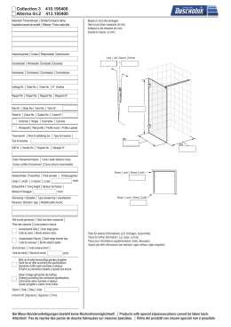
®
ALISON/S
Tastiera di Controllo LCD
LCD Control Keypad
Clavier de Control LCD
Teclado de Control LCD
I ITALIANO
INTRODUZIONE
La tastiera ALISON-S è utilizzabile nelle centrali Omnia, Academy40, Kyo16D, Kyo4-8-32 e Kyo100.
Questa tastiera presenta 3 led per segnalazioni varie.
INSTALLAZIONE
Per l’installazione della Tastiera procedere come descritto di seguito (vedere Fig. 1)
1. Aprire lo sportello 14.
2. Svitare le viti 15.
3. Togliere il coperchio 16.
4. Separare la Scheda Elettronica 11 dal fondo 12.
5. Se previsto, installare il Deviatore Antistrappo 2 come mostrato nel dettaglio ingrandito di Fig. 1.
, Il
Deviatore Antistrappo è opzionale (art. ASNC).
Il Deviatore Antistrappo deve essere installato per ottenere la certificazione IMQSISTEMI DI SICUREZZA al II Livello di Prestazione.
6. Passare il cavo per i collegamenti attraverso l’apertura 13.
7. Fissare il Fondo 12 alla parete o alla scatola predisposta tramite le opportune asole.
8. Se è stato installato il Deviatore Antistrappo 2, fissare il Tassello Antistrappo 1.
, ATTENZIONE - Il Deviatore Antistrappo è inefficace se la Tastiera viene fissata ad una scatola.
9.
10.
11.
12.
13.
14.
15.
Riagganciare la Scheda Elettronica 11 al Fondo 12.
Se installato, collegare il cavetto del Deviatore Antistrappo 2 al connettore 5.
Impostare il LIVELLO BPI come descritto nel paragrafo omonimo.
Eseguire i COLLEGAMENTI sulla morsettiera 10 come descritto nel paragrafo omonimo.
Impostare l’INDIRIZZO come descritto nel paragrafo omonimo.
Riagganciare il Coperchio 16 al Fondo 12.
Avvitare le viti 15.
Per una descrizione dettagliata delle spie presenti sul pannello della tastiera, fare riferimento al
manuale della centrale cui la tastiera stessa verrà collegata.
LIVELLO BPI
Il Livello BPI della Tastiera deve essere uguale a quello della centrale alla quale sarà collegata
(leggere le istruzioni della centrale per conoscere il suo Livello BPI).
Il Livello BPI della Tastiera si imposta tramite i ponticelli 3 e 9 come mostrato nella Tabella di Fig. 2.
INDIRIZZO
Ogni Tastiera collegata alla Centrale deve avere un indirizzo diverso. Per impostare l’indirizzo della
tastiera seguire la procedura descritta di seguito.
, La
centrale Kyo100 gestisce fino a 16 indirizzi. Tutte le altre centrali gestiscono solo i primi
8 indirizzi. Per impostazione predefinita (di fabbrica) alla prima accensione la tastiera è
indirizzata con il valore ‘01’.
)Nella
procedura descritta di seguito si tenga presente che in ogni momento il re-inserimento del
ponticello 9 o la ri-chiusura del microswitch antisabotaggio determinano l’uscita dalla fase di
programmazione ed il ritorno alla normale operatività della tastiera.
N.B. Affinchè possano essere ascoltati i segnali sonori, assicurarsi di non aver impostato il volume del
buzzer a 0 (Vedi paragrafo ‘REGOLAZIONE DEL VOLUME DEL BUZZER INTERNO’).
1.
2.
3.
4.
5.
Togliere il coperchio 8 della tastiera affinchè la stessa risulti in sabotaggio.
Collegare il bus BPI, (se non ancora collegato).
Togliere il ponticello 9.
Fase di attesa di 5 secondi con ponticello 9 tolto e microswitch antisabotaggio aperto (coperchio tolto).
La tastiera emetterà un beep lungo ad indicare l’ingresso nella fase di programmazione: sul
ALISON/S: 01
display apparirà “A
1”.
6. Agendo sui tasti C e D si imposta l’indirizzo desiderato.
7. Premere il tasto E per rendere effettivo l’indirizzo impostato oppure premere il tasto e per
annullare di fatto la programmazione. In entrambi i casi, dopo l’emissione di un beep lungo, sul
CALL SERVICE
display appare la scritta “C
E”: reinserire il ponticello 9 e chiudere il coperchio per
terminare la fase di programmazione.
Gli indirizzi assegnati devono essere diversi per tutti i dispositivi dello stesso tipo: questo significa
che possono coesistere nell’impianto tastiere ed inseritori con lo stesso indirizzo poiché l’Unità
Centrale è in grado di riconoscere il tipo di Dispositivo.
REGOLAZIONE DEL VOLUME DEL BUZZER INTERNO
Il Volume del Buzzer può essere regolato su tre livelli: nullo (buzzer muto), basso e alto. Il volume del
Buzzer si regola tramite il tasto e: tenere premuto il tasto e fino a quando non si ottiene il
volume desiderato.
I tre livelli possibili sono segnalati da beep di intensità e lunghezza diversa:
T beep corto e basso = Volume nullo (buzzer muto);
T beep di lunghezza e intensità media = Volume basso;
T beep lungo e alto = Volume alto.
REGOLAZIONE LUMINOSITÀ/CONTRASTO DEL DISPLAY
La retroilluminazione del Display e dei tasti si regola tramite i tasti A e
A per aumentare la retroilluminazione;
tenere premuto il tasto B per diminuire la retroilluminazione.
B:
T tenere premuto il tasto
T
, In
condizioni di riposo il livello della retroilluminazione è sempre quello minimo. Alla pressione
del primo tasto, il livello sarà quello impostato dall’utente: tale livello rimarrà per 30 secondi
successivi alla pressione dell’ultimo tasto per poi ritornare a quello minimo.
Il Contrasto del Display si regola tramite i tasti
C e D:
C per aumentare il Contrasto;
tenere premuto il tasto D per diminuire il Contrasto.
T tenere premuto il tasto
T
G ENGLISH
INTRODUCTION
The ALISON-S provides 3 status LEDs, and is intended for use with Omnia, Academy40, Kyo16D,
Kyo4-8-32 and Kyo100.
INSTALLATION
Work carefully through the following steps (see Fig. 1).
1. Open the flip 14.
2. Remove the screws 15.
3. Remove the frontplate 16.
4. Detach the PCB 11 from the backplate 12.
5. Insert the Snatch microswitch 2 — as per Fig. 1 (if required).
The Snatch microswitch is an accessory item (order code ASNC).
Keypads which are not fitted with Snatch microswitches, DO NOT COMPLY with IMQSECURITY SYSTEM Performance Grade II certification.
6. Pull the connection wires through the wire entry 13.
7. Using wall anchors, secure the backplate 12 to the wall or onto the outlet box.
8. Secure the Snatch bracket 1 to the wall (if required).
, If you are mounting the ALISON onto an outlet box, you cannot fit a Snatch microswitch.
9. Reattach the PCB 11 to the backplate 12.
10. Connect the Snatch microswitch 2 to the connector 5 (if necessary).
11. Set the BPI Level, as described under ‘SETTING THE BPI LEVEL’.
12. Complete the connections on the terminal board 10, refer to ‘CONNECTIONS’.
13. Assign the Address, as described under ‘ASSIGNING THE ADDRESS’.
14. Replace the frontplate 16 to the backplate 12.
15. Using the screws 15, secure the frontplate.
,
Refer to the Control panel Manual for the full description of the Keypad LEDs.
SETTING THE BPI LEVEL
The BPI Level of the keypad must match the BPI Level of the Control panel (refer to the Control panel
manual for details).
Using jumpers 3 and 9, as per the Table in Fig. 2, select the keypad BPI Level.
ASSIGNING THE ADDRESS
Devices of the same type cannot coexist at the same Address, therefore, you must assign a
different Address to each Keypad.
, The
KYO100 manages 16 Addresses, all other Control panels manage the first 8 Addresses
only. On first power up the Keypad will assume the preset Address ‘01’ (at default).
)You
can exit the Programming phase at any point in the following procedure by inserting the
jumper 9 or by closing the Tamper switch.
NOTE: If the buzzer volume is set at 0, the keypad will not emit any audible signals (refer to ‘ADJUSTING
THE ON-BOARD BUZZER VOLUME’).
1. Generate Tamper status by removing the frontplate.
2. Connect the Keypad to the Control panel BPI BUS.
3. Remove the Jumper 9 — after several seconds the Keypad will emit an audible signal (long beep)
ALISON/S: 01
to indicate access to the programming phase and the display will show “A
1”.
4. Using C or D, select the Address for the Keypad.
5. Press E to confirm, or press e to delete the setting — in both cases the Keypad will emit an
CALL SERVICE
audible signal, and the display will show the “C
E” message. Re-insert the jumper
9 and replace the frontplate, the Keypad will exit the programming session automatically.
ADJUSTING THE ON-BOARD BUZZER VOLUME
The Buzzer has 3 volume levels: Off (Mute), High and Low.
Using the e key, customize the Buzzer Volume.
Each volume level is identified by a specific beep:
T short low beep = Volume Off (Mute)
T long medium-high beep = Low Volume
T long high beep = High Volume
DISPLAY BRIGHTNESS AND CONTRAST
Using
A or B , customize the Brightness:
T press
T press
A to increase Brightness;
B to reduce Brightness.
, During
standby status the level of Brightness will be minimum. The selected level will activate
when any key is pressed, and will restore to 30 seconds after the last command.
Using C or D , customize the Contrast:
T press C to increase Contrast;
T press D to reduce Contrast.
F FRANÇAIS
INTRODUCTION
L’ALISON-S posséde 3 LEDs d’état, il est compatible avec Kyo16D, Kyo4-8-32 et Kyo100.
INSTALLATION
Suivre attentivement les étapes suivantes (voir Fig. 1).
1. Ouvrir le couvercle 14.
2. Déviser les vis 15.
3. Démonter la face avant 16.
4. Démonter le Carte 11 de la face ariiére 12.
5. Insérer l’autoprotection à l’arrachement 2 — comme indiqué Fig. 1 (si requis).
, Cette autoprotection est une option (code ASNC).
Cette autoprotection est nécessaire pour la certification Grade II.
6. Passer les câbles dans le passage de câble 13.
7. Fixer la face arriére 12 au mur.
8. Assurer de la fermeture de l’autoprotection 1 (si présent).
9. Replacer la carte 11 dans la face arriére 12.
10. Connecter le microswitch 2 au connecteur 5 (si présent).
11. Choisir le niveau BPI , comme décrit dans le paragraphe ‘Niveau du Bus BPI ’.
12. Completer la connexion du bornier 10, se réferer à ‘CONNEXIONS’.
13. Assigner une Adresse, comme décrit dans ‘ADRESSAGE DU CLAVIER’.
14. Remonter la face avant 16 sur la face arriére 12.
15. Utiliser les vis 15, pour fixer l’ensemble.
Se Référer au manuel de la centrale pour les explications concernant les LEDs.
NIVEAU DU BUS BPI
Le niveau de tension du Bus BPI du clavier doit être compatible avec le niveau de la centrale (se réferer
au manuel de la centrale).
Utiliser les pontets 3 et 9, comme indiqué dans la Table de la Figure 2.
ASSIGNER ADRESSE
Des périphériques de même type ne peuvent pas cohabiter sur la même Adresse, il faudra donc
assigner une adresse différente à chaque clavier.
, la KYO100 gére 16 Adresses, les autres centrales gérent
les 8 premières Adresses seulement.
A la première mise sous tension l’ Adresse ‘01’ est préfixée (usine).
) Vous
pouvez sortir de la phase de programmation suivante en insérant le pontet 9 ou si
l’autoprotection est fermée.
NOTE: Si le volume du buzzer est à 0, le clavier n’émettera aucun signal audible (se réferer à ‘ADJUSTEMENT
DU VOLUME DU BUZZER’).
1. Genéré une autoprotection du clavier.
2. Connecter le Bus BPI du clavier au Bus BPI de la centrale.
3. Supprimer le pontet 9 — aprés plusieurs secondes le clavier émettera un signal audible (long bip)
indiquant l’entrée en phase de programmation et l’écran affichera “A
1”.
ALISON/S: 01
4. Utiliser C ou D, pour selectionner l’ Adresse du clavier.
5. Presser E pour confirmer, ou presser e pour supprimer la paramétrage — dans laes 2 cas le
CALL SERVICE
clavier émettera un signal audible, et l’écran affichera “C
E”. Re-insérer le pontet
9 et refermer la face avant, le calvier sortira automatiquement de la phase de programmation.
ADJUSTEMENT DU VOLUME DU BUZZER INTEGRE
Le volume du Buzzer à 3 niveaux: Off (Silencieux), Haut et Bas.
Utiliser la touche e , pour modifier le volume.
Chaque niveau est identifié par bip spécifique:
T Court bip bas = Volume Off (silencieux)
T long bip moyen-haut = Volume bas
T long bip haut = Volume haut
LUMINOSITÉ ET CONTRASTE DE L’ECRAN
, La
Luminosité et le Contraste peut être adjusté durant un état de standby seulement.
Utiliser A et B , pour modifier la Luminosité:
A pour diminuer;
B
presse
pour augmenter.
T presser
T
, Durant
l’état de standby la luminosité sera au minimum. selectionné le niveau lorsqu’une
touche est utilisée, et retourne au minimum 30 secondes aprés la dernière commande.
Utiliser C et D , pour modifier le Contraste:
T presser C pour augmenter;
T presser D pour diminuer.
E ESPAÑOL
INTRODUCCION
El ALISON-S tien 3 LEDs de estado y funciona con Omnia, Academy40, Kyo16D, Kyo4-8-32 y
Kyo100.
INSTALACION
Siga cuidadosamente los siguientes pasos (vea la Fig. 1).
1. Abra la tapa 14.
2. Quite los tornillos 15.
3. Quite el frontal 16.
4. Separe el circuito 11 del fondo 12.
5. Inserte el microinterruptor 2 — como indica la Fig. 1 (si se necesita).
, The Snatch microswitch is an accessory item (order code ASNC).
Los teclados que no estén fijados con microinterruptores a la pared, NO CUMPLEN
con el Grado II de Protección del IMQ-SECURITY SYSTEM.
6. Pase los cables de conexion por la entrada de cable 13.
7. Use los agujeros de la pared para asegurar el fondo 12 a la pared o a una caja de conexiones.
8. Asegure el Sabotaje 1 a la pared (si se necesita).
, Si está montando el ALISON en una caja exterior, el microinterruptor antisabotaje no se puede colocar.
9. Vuelva a colocar el circuito 11 al fondo 12.
10. Conecte el microinterruptor de antisabotaje 2 (si se usa) a su conector 5.
11. Ponga el nivel del BPI como se describe en el punto ‘AJUSTE DEL NIVEL DEL BPI’.
12. Complete las conexiones en los terminales 10, vea el punto ‘CONEXIONES’.
13. Asigne las Direcciones, como se describe en el punto ‘ASIGNACIÓN DE DIRECCIONES’.
14. Vuelva a colocar la carcasa 16 al fondo 12.
15. Use los tornillos 15, para asegurar el frontal.
Vea el Manual de la Central para una descripcion completa de los teclados de LEDs.
AJUSTE DEL NIVEL DEL BPI
El nivel del BPI del teclado tiene que coincidir con el nivel BPI de la central (vea el manual de la Central
para detalles).
Use los puentes 3 y 9, segun se indica en la Tabla de la Fig. 2, para seleccionar el nivel del BPI del
teclado.
ASIGNACION DE DIRECCIONES
Los dispositivos del mismo tipo no pueden tener la misma direccion, por tanto, debe asignar una
direccion diferente a cada teclado.
, La KYO100 gestiona 16 Direcciones y el resto de las centrales solo las primeras 8 Direcciones.
La primera vez que se alimenta el teclado asume la direccion ‘01’ (de fábrica).
)Puede salir de la fase de programacion en cualquier punto insertando el puente 9 o cerrando el
interruptor de sabotaje.
NOTA: Si el volumen del zumbador está en 0, el teclado será incapaz, de emitir ninguna señal audible (vea
‘AJUSTE DEL VOLUMEN DEL ZUMBADOR’).
1. Genere un sabotaje quitando la carcasa.
2. Conecte el teclado al bus BPI de la Central.
3. Quite el puente 9 — después de varios segundos el teclado emitirá una señal audible (pitido largo)
ALISON/S: 01
para indicar el acceso a la fase de programacion y el display mostrará “A
1”.
4. Use C o D, para seleccionar la Direccion del teclado.
5. Pulse E para confirmar o pulse e para borrar el ajuste — en ambos casos el teclado emitirá
CALL SERVICE
unaseñal audible y el display mostrará el mensaje “C
E”. Vuelva a colocar el
puente 9 y el frontal, el teclado se saldrá automaticamente de la sesion de programacion.
AJUSTE DEL VOLUMEN DEL ZUMBADOR DEL CIRCUITO
El zumbador tiene 3 niveles de volumen: Off (apagado), Alto y Bajo.
Use la tecla e para personalizar el volumen del zumbador.
Cada nivel del volumen se identifica por un sonido específico:
T pitido corto y bajo = Volumen Off (Apagado)
T pitido largo y medio-alto = Volumen Bajo
T pitido largo y alto = Volumen Alto
BRILLO Y CONTRASTE DEL DISPLAY
A o B para personalizar el Brillo:
A para aumentar el brillo;
pulse B para reducir el brillo.
Use
T pulse
T
, Durante
el estado de reposo el Brillo será mínimo. El nivel seleccionado se activará cuandose
pulse una tecla, y se restaurará tras 30 segundos desde la ultima pulsacion.
Use C o D para personalizar el Contraste:
T pulse C para aumentar el Contraste;
T pulse D para reducir el Contraste.
BENTEL SECURITY s.r.l. si riserva il diritto di modificare le specifiche tecniche di questo prodotto senza preavviso.
BENTEL SECURITY s.r.l. reserves the right to change the technical specifications of this product without prior notice.
BENTEL SECURITY Srl. se réserve le droit de changer les spécifications techniques de ce produit sans préavis.
El contenido de este manual puede estar sujeto a modificaciones sin previo aviso y no representa ninguna obligación por parte del BENTEL SECURITY srl.
Fig. 1 - Parti - Parts - Composants - Partes
1 2
3
4
6
10
1
13 12
C
2abc
3 d ef
4 g hi
5
jkl
6m n o
D
7p qr s
8 t uv
9w xyz
ESC
ON
0
OF F#
11
A
B
5
7
9 7
8
15
15
14
N.
1
PARTI
2
3
!" #$%&'(
!-(./0
4
-
5
6 "
7 &&
8 -
9
!" #$%&'(
10 &
11 *$5
12 %$
13 14 *
15 ,
$
PARTS
" #!)
*%&(
COMPOSANTS
AP à l'ouverture
AP à l'arrachement
(Option)
Pontet du niveau BPI
(Voir la Figure 2)
PARTES
$+" #
,%&'(
(1./0
(./0
Ecran 2lignes, 16 caractéres
-
Connecteur de l'AP
"
2$
Buzzer
Microswith d'AP
-
Couvercle
Cubierta
$+" #
" #!)
Pontet du niveau BPI
,%&'(
*%&(
(Voir Figure 2)
$
$34
Bonier
-"
-
4
Carte
"
%$
Fond de boitier
5
$$
Entrée de câble
%
Couvercle
*
Vis
Fig. 2 - Setup e Collegamenti - Setup and Connections - Setup et Connexion - Ajuste y Conexionado
LIVELLO BPI
BPI LEVEL
NIVEAU BPI
NIVEL BPI
MORSETTIERA
3 def
5
6mno
D
7pqrs
8 tuv
9wxyz
ESC
ON
0
OF F
LIVELLO BPI
BPI LEVEL
NIVEAU BPI
NIVEL BPI
Use these Terminals for
the connections between
the BPI BUS and Control
panel
Programmable Alarm line
Positive power supply
TECHNICAL
SPECIFICATIONS
Voltage
Temperatura
di funzionamento
Operating Temperature
Livello di Prestazione
Performance Level
Stand By Current
jkl
2abcNC
4 ghi
5 j kl
6m no
7pqr s
8 t uv
3 def
COM
9wx yz
ON
0
OF F
C
NO
A
B
D
ESC
#
C
A
B
#
Ponticello 9
Jum per 9
Pontet 9
Puente 9
BORNIER DE CONNEXION
TERMINAL DE LA PLACA
Ces bornes permettent la Use estos terminales para
connexion du BUS BPI du conectar el Bus BPI a la
clavier à la centrale
Central
Entrée d'Alarme
Programmable
Positif d'alimentation
SPECIFICATION
TECHNIQUES
Tensione
Corrente assorbita
a riposo
Corrente Massima
(con Display acceso)
2abc
4 gh i
TERMINAL BOARD
+ Morsetti per il
C
collegamento del BUS
R
Dati con la Centrale.
Linea di allarme
L1
programmabile
+F Positivo di alimentazione
CARATTERISTICHE
TECNICHE
Ponticello 3
Jum per 3
Pontet 3
Puente 3
1
1
CARACTERÍSTICAS
TÉCNICAS
Tension
Tension
Température de
fonctionnement
Niveau de
Performance
Temperatura
funcionamiento
Courant au repos
Línea de alarma
programable
Positivo de alimentacion
10.5 V ÷ 14V
±5 %
+5 ÷ +40° C
Nivel de securidad
II
Corriente en reposo
40 mA
Maximum Current draw Courant Max consommé Corriente máxima
(with Display on)
(avec Ecran on)
(con Display acceso)
90 mA
BENTEL SECURITY s.r.l. - Via Gabbiano, 22 - Z.I. Santa Scolastica - 64013 CORROPOLI - TE - ITALY
Tel.: +39 0861 839060 - Fax: +39 0861 839065 - E-mail: [email protected] - http://www.bentelsecurity.com
ISTISBL3ALS2-S 0.3 210206 P7.0
Scaricare