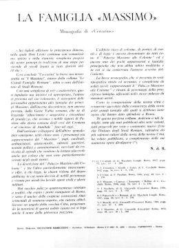
TOREX® S.r.l.
Via Canaletto, 139/A
41030 S. Prospero (MO) - ITALY
++39 / 059 / 8080811
fax ++39 / 059 / 908204
e-mail [email protected]
internet www.torex.it
IL
T
ILT
All rights reserved © WAMGROUP
OPERATING AND MAINTENANCE
BETRIEB UND WARTUNGSANLEITUNG
INSTRUKCJA OBSLUGI
USO E MANUTENZIONE
LEVEL INDICATOR
FÜLLSTANDANZEIGER
WSKAZNIK POZIOMU
INDICATORE DI LIVELLO
CATALOGUE No.
ISSUE
A
TO.900
CIRCULATION DATE OF LATEST UPDATE
100
CREATION DATE
03.03
- INDEX
- INHALTSVERZEICHNIS
ILT - SPIS TRESCI
- INDICE
03.03
2
INTRODUCTION, RULES AND GENERAL PROHIBITIONS.........................
GENERAL DIAGRAM.................................................................................
ORDER CODES.........................................................................................
OTHER VERSIONS OF THE ILT AND ACCESSORIES...............................
DIMENSION...............................................................................................
SAFETY NOCITES.....................................................................................
CONNECTIONS.........................................................................................
OPTIONS...................................................................................................
COMMISIONING - TESTING.......................................................................
COMMISIONING - TESTING-MOUNTING....................................................
MAINTENANCE..........................................................................................
SAFETY ITEMS.........................................................................................
DEMOLITION.............................................................................................
3<9
EINFÜHRUNG, ALLGEMEINE VORSCHRIFTEN GERÄTEBESCHREIBUNG..
ALLGEMEINES SCHEMA..................................................................................... 10
BESTELLCODES................................................................................................. 11
ANDERE ILT-VERSIONEN UND ZUBEHÖR.......................................................... 12 < 13
EINBAUMASSE.................................................................................................... 14
SICHERHEIT SHINWEISE.................................................................................... 15
ANSCHLÜSSE..................................................................................................... 16 < 17
VARIANTEN......................................................................................................... 18
ABNAHME UND INBETRIEBNAHME.....................................................................19
ABNAHME UND INBETRIEBNAHME-EINBAU....................................................... 20
WARTUNG............................................................................................................21 < 22
SICHERHEITSMAßNAHMEN................................................................................ 23
DEMANTELEMENT...............................................................................................24
WPROWDZENIE..........................................................................................
SCHEMAT OGOLNY...................................................................................
KODY PRODUKTOW..................................................................................
INNE WERSJE ILT I OSPRZET..................................................................
WYMIARY..................................................................................................
WSKAZOWKI BEZPIECZENSTWA............................................................
PRZYLACZA..............................................................................................
OPCJE.......................................................................................................
ODBIOR I URUCHOMIENIE........................................................................
URUCHOMIENIE I MONTAZ.......................................................................
KONSERWACJA.......................................................................................
SRODKI BEZPIECZENSTWA.....................................................................
DEMONTAZ................................................................................................
INTRODUZIONE, PRESCRIZIONI E DIVIETI GENERALI....................................... 3 < 9
SCHEMA GENERALE........................................................................................... 10
CODICI DI SCELTA............................................................................................... 11
ALTRE VERSIONI DELL’ ILT ED ACCESSORI...................................................... 12 < 13
DIMENSIONI......................................................................................................... 14
ISTRUZIONI DI SICUREZZA................................................................................. 15
CONNESSIONI..................................................................................................... 16 < 17
OPZIONI............................................................................................................... 18
MESSA IN SERVIZIO E COLLAUDO..................................................................... 19
MESSA IN SERVIZIO E COLLAUDO-INSTALLAZIONE..........................................20
MANUTENZIONE.................................................................................................. 21 < 22
PRECAUZIONI DI SICUREZZA..............................................................................23
DEMOLIZIONE...................................................................................................... 24
- INTRODUCTION, RULES AND GENERAL PROHIBITIONS
- EINFÜHRUNG, ALLGEMEINE VORSCHRIFTEN GERÄTEBESCHREIBUNG
ILT - WPROWADZENIE, OPIS URZADZENIA
- INTRODUZIONE, PRESCRIZIONI E DIVIETI GENERALI
This "OPERATING AND MAINTENANCE MANUAL" is an essential and
integral part of the machine and must be
readily available to operating and servicing personnel.
Die "BETRIEBS- UND WARTUNGSANLEITUNG" gehört zur Maschine und
muß an einem Ort aufbewahrt werden,
der dem Bedienungs- und Wartungspersonal gut zugänglich ist.
Niniejsza instrukcja obslugi stanowi
integralna czesc urzadzenia i powinna
byc przechowywana w jego poblizu
oraz powinna byc dostepna dla obslugi.
Wlasciciel, personel obslugi i konserThe owner, operator and maintenance Betreiber, Bediener und Wartungsperso- wacji sa zobowiazani zapoznac sie
Manager must be familiar with the con- nal sind verpflichtet, den Inhalt dieses z informacjami zawartymi w niniejszej instrukcji.
Handbuchs zu kennen.
tents of this Manual.
The description and illustrations used in Unter Beibehaltung der wesentlichen Producent zachowuje sobie prawo do
thus Manual are not binding on Manu- Merkmale der beschriebenen Maschinen wprowadzania zmian technicznych bez
behält sich der Hersteller vor, jederzeit wczesniejszego informowania klientow.
facturer.
an Geräteteilen und/oder am Zubehör
While the basic characteristics of the Änderungen im Sinne der Produktvermachine remain unchanged as de- besserung oder aus technisch oder kaufscribed, Manufacturer reserves the right männisch notwendigen Gründen vorzuto make any modifications to assemblies, nehmen.
parts and accessories it deems necessary for product improvement on for fabrication or marketing needs and this without prior notice and without being obliged
to update this Manual at the time of modifications.
03.03
3
Il presente libretto “ USO E MANUTENZIONE” costituisce parte integrante della
macchina e deve essere, facilmente reperibile dal personale addetto alla conduzione ed alla manutenzione.
L'utente, il conduttore e l'addetto alla manutenzione hanno l'obbligo di conoscere il contenuto dei presente libretto.
Le descrizioni e le illustrazioni contenuti
nella presente pubblicazione si intendono non impegnative,
Ferme restando le caratteristiche essenziali delle macchine descritte, la ditta costruttrice si riserva il diritto di apportare,
le eventuali modifiche di organi, dettagli
e, accessori, che riterrà convenienti per
il miglioramento del prodotto o per esigenze di carattere costruttivo o commerciale, in qualunque momento e senza
impegnarsi ad aggiornare tempestivamente questa pubblicazione.
- INTRODUCTION, RULES AND GENERAL PROHIBITIONS
- EINFÜHRUNG, ALLGEMEINE VORSCHRIFTEN GERÄTEBESCHREIBUNG
ILT - WPROWADZENIE, OPIS URZADZENIA
- INTRODUZIONE, PRESCRIZIONI E DIVIETI GENERALI
03.03
4
GENERAL PROHIBITIONS AND REGULATIONS
ALLGEMEINE VORSCHRIFTEN
PRZEPISY OGOLNE
- This machine must not be used even partially by
unauthorised personnel.
- The shop foreman or Department Manager is responsible for Machine operator training and for
checking training level achieved.
- The machine must not be used for purposes other than those is was designed for.
- Read carefully the warning notices attached to
the machine.
- Do not remove the warning notices attached to
the machine,
- When the machine is running, do not service,
repair, regulate the machine or carry out any other operation not strictly required by the work cycle. ,Before any of the above listed operations,
always disconnect the machine for all electric
power supply sources.
- DO not remove the guards and the safety devices on the machine,
- DO not start to work with protections opened or
do not open them during the work,
- Always wear safety gloves when working on the
machine.
- At the end of the work shift, disconnect the machine from the electric and hydraulic supply.
- Any repair, service or maintenance work, whether electrical or otherwise, must be in compliance
with CEI standards 64,8 462.2 463.1573.3.
- Jegliche auch teilweise Bedienung der Maschine durch hierzu nicht ausdrücklich autorisiertes
Personal ist untersagt.
- Der Betriebsleiter ist dafür verantwortlich, daß
das zur Bedienung autorisierte Personal in der
Bedienung der Maschine geschult wird.
- Die Maschine darf zu keinem anderen Zweck als
zu dem in diesem Handbuch beschriebenen verwendet werden.
- Die Gefahren- und Hinweisschilder an der Maschine müssen beachtet werden.
- Es ist verboten, die Gefahren- und Hinweisschilder an der Maschine zu entfernen.
- Wartungs-, Reparatur-, und/oder vom Hersteller
autorisierte Änderungsarbeiten dürfen nicht bei
laufender Maschine durchgeführt werden. Vor der
Durchführung solcher Arbeiten muß zuerst die
Stromversorgung zur Maschine unterbrochen
werden.
- Es ist verboten, die an der Maschine angebrachten Schutz- und Sicherheitseinrichtungen zu entfernen.
- Schulzeinrichtungen an der Maschine dürfen bei
Kontroll-, Wartungs-, Reparatur- und/oder Anderungsarbeiten weder fehlen noch während dieser Arbeiten entfernt werden.
- Nur mit Schutzhandschuhen an der Maschine arbeiten. Sei Betriebsschluß immer die Stromzufuhr oder, falls vorhanden, den Hydraulikkreislauf abschalten.
- Für alle elektrischen und nicht elektrischen Wartungsarbeiten die Vorschriften der Normen IEC
64-8 462.2 463.1573.3 beachten.
- Wyklucza sie obsluge urzadzenia przez
personel nie przeszkolony.
- Osoba nadzorujaca jest odpowiedzialna za
przeszkolenie obslugi.
- Urzadzenie nie moze byc uzywane do innych
celow niz podane w instrukcji.
- Nalezy przestrzegac tabliczek informacyjnych i ostrzegawczych umieszczonych na urzadzeniu.
sont interdits.
- Zabrania sie demontowania tabliczek znamionowych.
- zabrania sie przeprowadzania nieautoryzowanych przez producenta prac przy pracujacym
urzadzeniu.Podczas przeprowadzania takich prac
nalezy wylaczyc zasilanie.
- Zabrania sie usuwania zabezpieczen pradowych.
- Zabezpieczenia tego typu nie moga byc usuniete ani pomylkowo ani podczas tych prac.
- stosowac rekawice ochronne podczas prac
kontrolnych konserwatorskich lub napraw.
- podczas wykonywaniatego typu prac zawsze
nalezy wylaczyc prad.
- Podczas prac elektrycznych nalezy stosowac
- przepisy norm IEC 64-8 462.2 463.1573.3 -
PRESCRIZIONI E DIVIETI GENERALI
E’ vietato l'uso, anche parziale, dell'attrezzatura
da parte del personale non espressamente autorizzato. L'istruzione del personale preposto all'uso è da realizzare e verificare a cura dei capo
officina e dei capi reparto.
E’ vietato l'uso dell'attrezzatura per modalità diverse da quelle per cui è stata prevista.
Leggere con attenzione le targhe di avvertenza e
pericolo poste sulla macchina.
E’ vietato rimuovere le targhe di avvertenza e
pericolo sulla macchina.
E’ vietato manutenzionare, eseguire riparazioni,
modifiche e quanto non strettamente necessario al ciclo di lavoro con la macchina in movimento. Prima di tutto è obbligatorio disinnestare
tutte le alimentazioni elettriche alla macchina.
E’ vietato rimuovere le protezioni e le sicurezze
presenti sulla macchina.
E’ vietato iniziare il lavoro con le protezioni aperte o aprirle durante il lavoro.
Operare sulla macchina solo con i guanti di protezione.
Al termine dei periodi di lavoro scollegare sempre la macchina dalle alimentazioni elettriche e
idrauliche.
Qualsiasi manutenzione elettrica e non elettrica
deve attenersi alle norme CEI 64-8 462.2
463.1573.3.
03.03
- INTRODUCTION, RULES AND GENERAL PROHIBITIONS
- EINFÜHRUNG, ALLGEMEINE VORSCHRIFTEN GERÄTEBESCHREIBUNG
ILT - WPROWADZENIE, OPIS URZADZENIA
- INTRODUZIONE, PRESCRIZIONI E DIVIETI GENERALI
5
SETTORI DI APPLICAZIONE
FIELDS OF APPLICATION
VERWENDUNG
OBSZAR STOSOWANIA
The device is used for level monitoring
in all types of containers and silos.
It can be used with all powdery and granular bulk materials that do not show a
strong propensity to form crusts or deposits. A wide range of application is also
found in foodstuff manufacturing.
Das Gerät wird verwendet zur Füllstandüberwachung in Behältern und Silos aller Art.
Es ist einsetzbar für alle pulverförmigen
Schüttgüter und Granulate, die nicht zu
starker Ansatzbildung neigen. Ein breiter Anwendungsbereich findet sich auch
in der Nahrungsmittelindustrie.
Urzadzenie stosuje sie do pomiaru
Il dispositivo è utilizzato per il monitoraggio del livello all’interno di container e sili
i kontroli poziomu produktu sypkiego
w silosie.
di qualsiasi tipo.
Stosuje sie do wszystkich sypkich produk- Può essere utilizzato in presenza di poltow i granulatow, ktore nie maja sklonnosci veri e granulati con scarsa tendenza alla
formazione di incrostazioni o depositi. Un
do nawarstwiania sie.
Szerokie zastosowanie znajduja w prze- ampio settore di applicazione è inoltre
rappresentato dall’industria alimentare.
mysle spozywczym.
A selection of fields of application
Einige Einsatzgebiete
Obszary zastosowan
- industry of building materials for lime,
styrofoam, moulding sand, etc.
- food industry for milk powder, flour, salt,
etc.
- plastics industry for plastics granules
etc.
- timber industry
- chemical industry
- mechanical engineering etc.
- Baustoffindustrie: Kalk, Styropor,
Formsand u.a.
- Nahrungsmittelindustrie: Milchpulver,
Mehl, Salz u.a.
- Kunststoffindustrie: Kunststoffgranulate u.a.
- Holzindustrie
- Chemische Industrie
- Allgemeiner Anlagenbau
- Budownictwo:wapno,styropor,piasek
- Przemysl spozywczy: mleko w proszku
maka, sol i.in.
- Tworzywa sztuczne: granulat PET
- Przemysl drzewny
- Przemysl chemiczny
- Budowa urzadzen
-
Possibili applicazioni
Industria materiali da costruzione per
calce, styrofoam, sabbia da fonderia,
ecc.
Industria alimentare per latte in polvere, farina, sale, ecc.
Industria materie plastiche per granulati plastici, ecc.
Industria dei legnami
Industria chimica
Costruzioni meccaniche, ecc.
- INTRODUCTION, RULES AND GENERAL PROHIBITIONS
- EINFÜHRUNG, ALLGEMEINE VORSCHRIFTEN GERÄTEBESCHREIBUNG
ILT - WPROWADZENIE, ZASADY UZYTKOWANIA
- INTRODUZIONE, PRESCRIZIONI E DIVIETI GENERALI
TYPE
Level Indicator
03.03
6
MASCINENTYP
TYP
TIPO
Füllstandsanzeiger mit rotierendem wskaznik poziomu
Indicatore di Livello
Drehfügel.
DESCRIPTION
OPIS
DESCRIZIONE
BESCHREIBUNG
Level indicator with rotating paddle.
Wskaznik poziomu z obrotowa lopatka
Indicatore di livello a pala rotativa
Füllstandgrenzschalter
USE
ZASTOSOWANIE
FUNZIONE D’USO
Designed to signal the presence of ma- VERWENDUNGSZWECK
urzadzenie sluzy do pomiaru poziomu Servono a segnalare la presenza di materiale in sili, tramogge, ect, e sono utiterials in silos, hoppers, etc., commonly Mit diesen Geräten wird der Füllstand in materialu w silosach, zbiornikach itp.
used for materials having a density rang- Silos, Trichtern usw. von Medien mit z produktem sypkim o ciezarze usy- lizzati comunemente per materiali con
densità tra 0.5 e 2 t/m3.
ing from 0.5 e 2 t/m3.
Schüttgewichten von 0.5 bis 2 t/m3 an- powym 0,5 do 2 t/m3.
gezeigt.
03.03
- INTRODUCTION, RULES AND GENERAL PROHIBITIONS
- EINFÜHRUNG, ALLGEMEINE VORSCHRIFTEN GERÄTEBESCHREIBUNG
ILT - WPROWADZENIE, ZASADY UZYTKOWANIA
- INTRODUZIONE, PRESCRIZIONI E DIVIETI GENERALI
7
CONTROINDICAZIONI
IMPROPER USE
UNZULÄSSIGE VERWENDUNGS- PRZECIWWSKAZANIA
ZWECKE
ILT level indicators are not designed to
work in dangerous conditions or with
dangerous materials. If the machine has
to operate in these conditions, the manufacturer must be informed.
Die Füllstandanzeiger der Modellreihe
ILT sind weder für gefährliche Anwendungen noch zum Handling von gefährlichen Medien geeignet. Sollte der Betreiber eine ILT - Füllstandanzeiger für
gefährliche Medien bzw. Anwendungen
einsetzen wollen, so muß er unbedingt
vorher den Hersteller um Erlaubnis fragen.
Czujniki poziomu ILT nie nadaja sie do
niebezpiecznych mediow lub niebezpiecznych zastosowan.
Wprzypadku takich zastosowan nalezy
zawsze zapytac sprzedawce o zgode.
Gli indicatori di livello standard della ILT
NON sono stati progettati per operare in
condizioni o con materiali pericolosi pertanto quando la macchina deve assolvere a queste esigenze è d'obbligo informare il costruttore.
Dangerous materials:
- explosives,
- toxic,
- flammable,
- harmful and similar.
Als gefährliche Medien gelten:
- explosive,
- giftige,
- feuergefährliche,
- in irgendeiner Weise schädliche.
Przyklady niebezpiecznych mediow:
Si ritengono materiali pericolosi:
- esplosivi,
- tossici,
- infiammabili,
- nocivi e/o simili.
-
eksplozyjne
toksyczne,
latwopalne,
jakkolwiek szkodliwe
-INTRODUCTION, RULES AND GENERAL PROHIBITIONS
-EINFÜHRUNG, ALLGEMEINE VORSCHRIFTEN GERÄTEBESCHREIBUNG
ILT -WPROWADZENIE, ZASADY UZYTKOWANIA
-INTRODUZIONE, PRESCRIZIONI E DIVIETI GENERALI
ME C H AN IC AL D ATA
enclosure
IP 55
mains voltage
process connection
tread G1½" and G2½"
material process-connection
plastic
installed load
connection
terminal
material vane shaft and measuring
stainless steel
vane
friction clutch
protection of the gearing of impacts of the
measuring vane
pickup delay
approx. 1.3 sec.
sensitivity
adjustable via reset force of spring in three positions
speed of measuring vane
1 1/min.
ME C H AN IS C H E D AT E N
screwed cable
gland
signal output
connection
diagram
protection class
E L E C T R IC AL D ATA
24V/48V 50-60 Hz -110/220V 50/60 Hz
24V DC (all voltage + 10% / -15)%
3VA(3w)
1 x max. 1.5 mm2
IP 55
Anschlußgewinde
tread G1½" und G2½"
E L E K T R IS C H E D AT E N
24V/48V 50-60 Hz -110/220V 50/60 Hz
24V GS (alle Spannungen +10%/ - 15%)
Anschlußleistung 3VA(3w)
Material des Anschlußgewindes
Kunststoff
Anschlußklemmen 1 x max. 1.5 mm2
Rostfreier Stahk
Reibungskupplung
Schutz der Zahnräder vom Stößen des Meßflügels
Signalverzögerung
c.a 1.3 sec.
Empfindlichkeit
Einstelbar durch Rückholfeder mit drei Stellungen
Flügelgeschwindigkeit
1 Umdrehung/min.
8
OP E R AT IN G C ON D IT ION S
container over-pressure
max. 0.8 bar
temperature inside vessel
ambient temperature at the
housing
-20°C..+80°C
-20°C..+70°C
1 x PG 13.5"
(add. 1x blank-off flange PG 13.5)
plastic
floating microswich AC max. 250V, 2A,
500W (cos=1) GS 300V max., 60W
AC version: on: on printed circuit
DC version: inside the lid
I
Gehäuse
Material von Welle und Flügel
03.03
Netzspannung
Kabelverschraub- 1 x PG 13.5"
ung
(1xStopfen PG 13.5) aus Kunststoff
Schwimmender Mikroschalter WS 250V
Ausgangssignal
max., 2A, 500W (cos=1) GS 300V max.,
60W
WS-Version: auf Leiterplatte
Anschlußplan
GS-Version: im Deckel
Schutzart
I
B E T R IE B S B E D IN GU N GE N
Behälterüberdruck
max. 0.8 bar
temperatur im Behälter
Umgebungstemperatur
innerhalb des Gehäuse
-20°C..+80°C
-20°C..+70°C
03.03
-INTRODUCTION, RULES AND GENERAL PROHIBITIONS
-EINFÜHRUNG, ALLGEMEINE VORSCHRIFTEN GERÄTEBESCHREIBUNG
ILT -WPROWADZENIE, ZASADY UZYTKOWANIA
-INTRODUZIONE, PRESCRIZIONI E DIVIETI GENERALI
C R AC T E R IS T IQU E S ME C AN IQU E S
nveloppe
IP 5
Tension de
secteur
C AR AC T E R IS T IQU E S E L E C T R IQU E S
24V/48V 50-60 Hz -110/220V 50/60 Hz
24V CC (toutes les tensions + 10% / -15%)
Filetage de raccord
G1½" et G2½"
Charge installée
3VA(3w)
Matière du filetage de raccord
Plastique
Borne
1 x 1.5 mm2 max.
Matière de l'arbre et de la palette
Acier inoxydable
Serre-câble vissé
Commande d' embrayage
protection des engranages de l'impact de la palette
Retard de signal
1.3 s. environ.
Sensibilité
réglable par le rappel du ressort dans trois positions
Vitesse de la palette
1 tour/min
involucro
IP 55
Signal de sortie
Diagramme de
connexion
Classe de
protection
mozzo di collegamento
innesto a frizione
ritardo di segnale
tensione di rete
D AT I E L E T T R IC I
24V/48V 50-60 Hz -110/220V 50/60 Hz
24V CC (tutte le tensioni + 10% / -15%)
carico installato
plastica
morsetto d'attacco 1 x 1.5 mm2 max.
Acciaio inossidabile
Pressacavo
avvitato
1.3 sec. circa
sensibilità
regolabile mediante il richiamo della molla in tre posizioni
velocità della paletta
1 giro/min
segnale di uscita
diagramma di
connessione
Classe di
protezione
max. 0.8 bar
Température à l'intérieur du
-20°C..+80°C
conteneur
Température ambiante à
-20°C..+70°C
l'intérieur du corps de l'indicateur
I
filettatura G1½" e G2½"
protezione degli ingranaggi dall'impatto della paletta
C ON D IT ION S D E S E R V IC E
Surpression conteneur
1 x PG 13.5"
(1x bouchon PG 13.5) en plastique
Microrupteur flottant CA 250V max., 2A,
500W (cos=1) CC 300V max., 60W
Version CA: sur circuit imprimé
Version CC: à l'intérieur du couvercle
D AT I ME C C AN IC I
materiale del mozzo di
collegamento
materiale dell' albero e della
paletta
9
3VA(3w)
1 x PG 13.5"
(1x tappo PG 13.5) in plastica
Microinterruttore flottante CA 250V max.,
2A, 500W (cos=1) CC 300V max., 60W
Versione CA: su circuito stampato
Versione CC: all'interno del coperchio
I
C ON D IZION I D I E S E R C IZIO
sovrapressione contenitore
max. 0.8 bar
temperatura all'interno del
-20°C..+80°C
contenitore
Temperatura ambiente
-20°C..+70°C
all'interno del corpo indicatore
- GENERAL DIAGRAM
- ALLGEMEINES SCHEMA
ILT - SCHEMAT IDEOWY
- SCHEMA GENERALE
03.03
10
Item
p o s.
D escrip tio n - Benennung
D esig n atio n - D escrizione
Qu an tity - S tück
Qu an titè - Quantità
A
Cover - D eckel
ouvercle - C o perc
1
B
Frame - Gehäuse
Corps - C o rpo
1
C
Shaft support
Anschlußgewinde m it Wellenführung
Support arbre
Suppo rto albero
1
D
Paddle - D rehfügel
Palette - Paletta
1
E
Shaft - Welle
Arbre - Albero
1
03.03
- ORDER CODES
- BESTELLCODES
ILT - CODES DE SELECTION
- CODICI DI SCELTA
ILT
A
11
0
0
2
5
A
1 + ½“ - 2 + ½“
1 + ¼“ NPT cilindrical - Zylindrisch - cylindryczny - cilindrico
flanged - geflanscht - z kolnierzem - flangiato
Triple palette - Schaufel Dreiflügelig -potrojna kopatka - Paletta
A 24/48 V - 50/60 Hz
C 110/220 V - 50/60 Hz
D 24 V - DC/GS/CC/CC
Level indicator - Füllstandsmelder
Czujnik poziomu - Indicatore di livello
- OTHER VERSIONS OF THE ILT AND ACCESSORIES
- ANDERE ILT-VERSIONEN UND ZUBEHÖR
ILT - INNE WERSJE I AKCESORIA
- ALTRE VERSIONI DELL’ILT ED ACCESSORI
Typ e
C ode
V E R S ION S OF ILT WIT H R OTAT ION C ON T R OL
ILT C 0S 115
ILT with 115 V/AC rotation control
ILT C 0S 230
ILT with 230 V/AC rotation control
ILT D 0S 024
ILT with 24 V/DC rotation control
V E R S ION S OF ILT F OR E X P L OS IV E ZON E S
ILTA0AX
ILT 24 V/AC ATEX II 1/2 D "dust EX"
ILTA0B X
ILT 48 V/AC ATEX II 1/2 D "dust EX"
ILT C 0AX
ILT 115 V/AC ATEX II 1/2 D "dust EX"
ILT C 0B X
ILT 230 V/AC ATEX II 1/2 D "dust EX"
AC C E S S OR IE S
4538020100
Sleeve 1+1/2"
4538020150
Sleeve 2+1/2"
13N 07001A
Double blade 98x200
3850011200
Rectangular blade 98x250
3848004500
Green lamp cover PG 13,5
3848004520
Red lamp cover PG 13,5
3848004000
24 volt lamp
3848004050
48 volt lamp
3848004100
115 volt lamp
3848004150
230 volt lamp
3850001022
Extension* for shaft 500 mm
3850001026
Extension* for shaft 1000 mm
3850001038
Pin for "old" shaft extensions
3850001039
Pin for new shaft extensions 115mm
3848004510
Green lamp cover M20x1.5
3848004530
Red lamp cover M20x1.5
*assembly of the extensions is permitted only vertically and for a maximum of 3 m.
03.03
12
Typ
C ode
ILT-V E R S ION E N MIT R OTAT ION S S T E U E R U N G
ILT C 0S 115
ILT mit Rotationssteuerung 115 V/AC
ILT C 0S 230
ILT mit Rotationssteuerung 230 V/AC
ILT D 0S 024
ILT mit Rotationssteuerung 24 V/DC
ILT -V E R S ION E N F Ü R E X -B E R E IC H E
ILTA0AX
ILT 24 V/AC ATEX II 1/2 D "dust EX"
ILTA0B X
ILT 48 V/AC ATEX II 1/2 D "dust EX"
ILT C 0AX
ILT 115 V/AC ATEX II 1/2 D "dust EX"
ILT C 0B X
ILT 230 V/AC ATEX II 1/2 D "dust EX"
ZU B E H ÖR
4538020100
Muffe 1+1/2"
4538020150
Muffe 2+1/2"
13N 07001A
Doppelschaufel 98x200
3850011200
Rechteckschaufel 98x250
3848004500
Lampenabdeckung Grün PG 13,5
3848004520
Lampenabdeckung Rot PG 13,5
3848004000
Lampe 24 Volt
3848004050
Lampe 48 Volt
3848004100
Lampe 115 Volt
3848004150
Lampe 230 Volt
3850001022
Verlängerung* für Welle 500 mm
3850001026
Verlängerung* für Welle 1000 mm
3850001038
Bolzen für Verlängerungen Welle "old"
3850001039
Bolzen für Verlängerungen Welle "new" 115 mm
3848004510
Lampenabdeckung Grün M20x1.5
3848004530
Lampenabdeckung Rot M20x1.5
*: Es sind nur Verlängerungen bis zu max. 3 m zulässig, die vertikal zu montieren sind.
- OTHER VERSIONS OF THE ILT AND ACCESSORIES
- ANDERE ILT-VERSIONEN UND ZUBEHÖR
ILT - INNE WERSJE I AKCESORIA
- ALTRE VERSIONI DELL’ILT ED ACCESSORI
Typ e
C ode
V E R S ION E S ILT AV E C C ON T R OL E D E R OTAT ION
ILT C 0S 115
ILT avec controle de rotation 115 V/AC
ILT C 0S 230
ILT avec controle de rotation 230 V/AC
ILT D 0S 024
ILT avec controle de rotation 24 V/DC
V E R S ION N E S ILT P OU R ZON E S E X P L OS IV E S
ILTA0AX
ILT 24 V/AC ATEX II 1/2 D "dust EX"
ILTA0B X
ILT 48 V/AC ATEX II 1/2 D "dust EX"
ILT C 0AX
ILT 115 V/AC ATEX II 1/2 D "dust EX"
ILT C 0B X
ILT 230 V/AC ATEX II 1/2 D "dust EX"
AC C E S S OIR E S
4538020100
Manchon 1+1/2"
4538020150
Manchon 2+1/2"
13N 07001A
Double palette 98x200
3850011200
Palette rectangulaire 98x250
3848004500
Couvre lampe Vert PG 13,5
3848004520
Couvre lampe Rouge PG 13,5
3848004000
Lampe 24 Volt
3848004050
Lampe 48 Volt
3848004100
Lampe 115 Volt
3848004150
Lampe 230 Volt
3850001022
Prolonge* pour arbre de 500 mm
3850001026
Prolonge* pour arbre de 1000 mm
3850001038
Pivot pour prolonge arbre "old"
3850001039
Pivot pour prolonge arbre new 115 mm
3848004510
Couvre lampe Vert M20x1.5
3848004530
Couvre lampe Rouge M20x1.5
*: Le montage des prolonges est permis seulement en vertical et pour un maximum de 3 m.
03.03
13
T ip o
C o d ice
V E R S ION I ILT C ON C ON T R OL L O D I R OTAZION E
ILT C 0S 115
ILT con controllo rotazione 115 V/AC
ILT C 0S 230
ILT con controllo rotazione 230 V/AC
ILT D 0S 024
ILT con controllo rotazione 24 V/DC
V E R S ION I ILT P E R ZON E E S P L OS IV E
ILTA0AX
ILT 24 V/AC ATEX II 1/2 D "dust EX"
ILTA0B X
ILT 48 V/AC ATEX II 1/2 D "dust EX"
ILT C 0AX
ILT 115 V/AC ATEX II 1/2 D "dust EX"
ILT C 0B X
ILT 230 V/AC ATEX II 1/2 D "dust EX"
AC C E S S OR I
4538020100
Manicotto 1+1/2"
4538020150
Manicotto 2+1/2"
13N 07001A
Paletta doppia 98x200
3850011200
Paletta rettangolare 98x250
3848004500
Copri lampada Verde PG 13,5
3848004520
Copri lampada Rosso PG 13,5
3848004000
Lampada 24 Volt
3848004050
Lampada 48 Volt
3848004100
Lampada 115 Volt
3848004150
Lampada 230 Volt
3850001022
Prolunga* per albero da 500 mm
3850001026
Prolunga* per albero da 1000 mm
3850001038
Perno per prolunghe albero "old"
3850001039
Perno per prolunghe albero new 115 mm
3848004510
Copri lampada Verde M20x1.5
3848004530
Copri lampada Rosso M20x1.5
* il montaggio delle prolunghe è consentito solo in verticale e per un massimo di 3 m.
- DIMENSION
- EINBAUMASSE
ILT - WYMIARY
- DIMENSIONI
03.03
14
03.03
- SAFETY NOCITES
ILT - SICHERHEITSHINWEISE
BEZPIECZENSTWO UZYTKOWANIA
- ISTRUZIONI DI SICUREZZA
15
- For terminal connection of the device, the lo- - Für den elektrischen Anschluß müssen die ört- - Przylacza elektrycznego dotycza przepisy
cal regulations must be observed.
lichen Vorschriften oder VDE 0100 beachtet
lo ka lne.
- For terminal connection of the device in arewerden.
- Nalezy przestrzegac przepisow dotyczacych
as in which there is the danger of dust explo- - Für den elektrischen Anschluß in StEx Zone
pracy w warunkach zagrozenia wybuchem
sion zone 10, the pertinent local regulations
10 gefährdeten Bereichen müssen die entspr.
w strefie 10 odnosnie przewodow elekfor the installation and connection of electriVorschriften für die Verlegung u. Anschluß
trycznych.
cal wires must be observed.
elektr. Leitungen beachtet werden.
- Provide protection for relay contacts and output
transistors to protect the device against spikes
with inductive loads.
- Compare the mains voltage applied with the
specifications given on the electronic module before switching the device on.
- Make sure that max. 8mm of the pigtails are
bared (danger of contact with live parts).
- Make sure that the boots for protecting cable terminations are not longer than 8mm (danger of
contact with live parts).
Make sure that the screwed cable gland safely
seals the cable and that it is tight (danger of water
intrusion).
- A voltage-disconnecting switch must be provided near the device.
- In the case of inexpert handling or handling malpractice, the electric safety of the device cannot
be guaranteed.
- In the case of a defect, the distribution voltage
must automatically be cut off by a FI protective
switch so as to protect the user of the device
from indirect contact with dangerous electric tensions.
- Zum Schutz vor Spannungsspitzen bei induktiven Lasten einen Schutz für Relaiskontakte /
Ausgangstransistoren vorsehen.
- Vor Einschalten des Gerätes Anschlußspannung
mit Angaben auf Elektronikmodul vergleichen.
- Darauf achten, daß die Anschlußlitzen max. 8
mm abisoliert werden (Gefahr der Berührung
spannungs- führender Teile).
- Darauf achten, daß die Aderendhülsen der Anschlußkabel max. 8 mm lang sind (Gefahr der
Berührung spannungsführender Teile).
- Darauf achten, daß die Kabelverschraubung das
Kabel sicher dichtet u. fest angezogen ist (Wassereintritt).
- Es muß in der Nähe des Gerätes ein Schalter
als Trennvorrichtung für die Anschlußspannung
vorgesehen werden.
- Bei unsachgemäßem Gebrauch des Gerätes ist
die elektr. Sicherheit nicht gewährleistet.
- Zum Schutz gegen indirektes Berühren gefährlicher Spannung muß im Fehlerfall ein automatisches Ausschalten (FI - Schutzschalter) der Versorgungsspannung gewährleistet sein.
- Per la connessione dei morsetti del dispositivo attenersi alle normative locali.
- Per la connessione dei morsetti in zone 10, con
pericolo dovuto alla presenza di polveri esplosive, attenersi alle normative vigenti per l’installazione e la connessione di cavi elettrici.
- W celu zabezpieczenia przed przeciazeniami
nalezy przewidziec tranzystory przeciwprzeciazeniowe.
- Przed podlaczeniem urzadzenia nalezy sprawdzic
napiecie sieciowe z napieciem modulu elektronicznego.
- Nalezy zwrocic uwage aby przewody byly
odizolowane na dlug. max 8 mm
- Zwrocic uwage aby przewod byl dokrecony
(niebezpieczenstwo kontaktu z woda).
- W poblizu urzadzenia musi byc zabudowany
wylacznik bezpieczenstwa.
- Nie gwarantujemy bezpieczenstwaelektrycznegow przypadkach zastosowania niezgodnego z
przeznaczeniem.
- W celu zabezpieczenia przed kontaktem
z niebezpiecznym napieciem nalezy zabudowac
wylacznik bezpieczenstwa FI.
Fornire una protezione per i contatti dei relè e i
transistor d’uscita contro i picchi di tensione con
cariche induttive.
Verificare la tensione di alimentazione applicata
in base alle specifiche riportate sul modulo elettronico prima dell’avviamento del dispositivo.
Assicurarsi che la superficie scoperta dei fili connettori non superi gli 8 mm (pericolo di contatto
con parti sotto tensione).
Assicurarsi che le guaine di protezione delle terminazioni dei cavi non superino gli 8 mm di lunghezza (pericolo di contatto con parti sotto tensione).
Assicurarsi che il pressacavo stringa il cavo in
modo sicuro, fissandolo adeguatamente (pericolo di infiltrazione d’acqua).
Collocare un interruttore di tensione nei pressi del
dispositivo.
Non si garantisce la sicurezza elettrica del dispositivo in caso di impiego improprio o non conforme.
- In caso di guasto, l’alimentazione dovrà essere
automaticamente interrotta mediante un interruttore di protezione FI al fine di proteggere l’utilizzatore dal contatto indiretto con tensioni elettriche pericolose.
- CONNECTIONS
- ANSCHLÜSSE
ILT - PRZYLACZE ELEKTRYCZNE
- CONNESSIONI
ELECTRICAL CONNECTIONS
Take note of the power supply indicated on
the legend plate.
Always observe safety regulation (See Safety
Instructions - IEC....)
ELEKTRISCHE ANSCHLÜSSE
Anschlußspannung auf dem Typenschild
beachten.
Die Sicherheitsvorschriften (siehe IEC) sind
ständing zu beachten.
03.03
16
PRZYLACZE ELEKTRYCZNE
Sprawdzic napiecie z napieciem podanym
ptabliczce znamionowej.
Nalezy przestrzegac przepisow bezpieczenstwa (IEC...).
COLLEGAMENTI ELETTRICI
Il collegamento deve essere eseguito in accordo alla tensione riportata sulla targhetta
identificativa.
Fare sempre attenzione alle norme di sicurezza, vedi scheda (rif.IEC....).
DC version - GS-Version - Wersja CC - Versione CC
R
TOREX Srl
R
WAMGROUP
ILTD0
DC version: connection diagram inside of the lid
GS-Version: Anschlußdiagramm im Inneren des Deckels
Wersja CC: diagram przylaczy wewnetrznych
Versione CC: diagramma di connessione all‘interno del coperchio
03.03
- CONNECTIONS
- ANSCHLÜSSE
ILT - PRZYLACZA
- CONNESSIONI
17
AC version - WS-Version - wersja CA - Versione CA
R
TOREX Srl
R
WAMGROUP
ILTA0
R
TOREX Srl
R
WAMGROUP
ILTC0
AC version: connection diagram on the electronic board
(as shown on the drawing left)
WS-Version: Anschlußdiagramm auf der Leiterplatte
(siehe Zeichnung links)
Wersja CA: diagram przylaczen na plytce
( tak jak pokazano na rysunku z lewej strony)
Versione CA: diagramma di connessione sul quadro elettronico
(come indicato nel disegno a sinistra)
- OPTIONS
- VARIANTEN
ILT - OPCJE
- OPZIONI
03.03
18
R
R
TOREX Srl
R
TOREX Srl
R
WAMGROUP
WAMGROUP
ILTD0S024
ILTC0-S230
R
TOREX Srl
R
WAMGROUP
AC version with rotation control
WS-version mit Prüfung der Drehung
Wersja CA z kontrola obrotow
Versione CA con indicatore di rotazione
ILTC0-S115
DC version with rotation control
GS-version mit Prüfung der Drehung
Wersja CC z kontrola obrotow
Versione CC con indicatore di rotazione
03.03
- COMMISIONING - TESTING
- ABNAHME UND INBETRIEBNAHME
ILT - ODBIOR I URUCHOMIENIE
- MESSA IN SERVIZIO E COLLAUDO
view electronic board only
Ansicht nur von der Leitungsplatte
Widok plytki elektrycznej
vista solamente del quadro elettronico
19
switching logic
logiscer Umschaltplan
schemat logiczny
schema logico di commutazione
AC max.250V , 2A, 500W(cos=1)
DC max.300V , 2A, 60W
terminals 1 x max.1,5 mm2
CA 250V max., 2A, 500W(cos=1)
CC 300V max., 2A, 60W
bornes 1 x 1,5 mm2 max.
WS 250V max., 2A, 500W(cos=1)
GS 300V max., 2A, 60W
Klemmen 1 x 1,5 mm2 max.
CA 250V max., 2A, 500W(cos=1)
CC 300V max., 2A, 60W
morsetti 1 x 1,5 mm2 max.
ILT -
COMMISIONING - TESTING
ABNAHME UND INBETRIEBNAHME
ODBIOR I URUCHOMIENIE
MESSA IN SERVIZIO E COLLAUDO
03.03
MOUNTING
EINBAU
MONTAZ
INSTALLAZIONE
20
The unit must be mounted with the thread at the container. Mounting may be vertical, oblique or horizontal. During mounting, turn the housing in
the right direction. This is possible with a suitable sealing material which fix and seal the unit (to counter the plastic screw part with the container
is only by hand not by tools allowed).
The screwed cable gland (or plug) must show downwards (see drawing right hand). This makes sure, that the unit works fine and protects, that
water enters into the housing throught the screwed cable gland. It is not possible to turn the housing after fixing the thread.
The electrical connections are made in accordant with the connection diagram.
Make sure, that the cable in the screwed cable gland is seated tightly without fail.
Adjusting the unit at site is not required.
Die Einheit muß mit dem Gewinde am Behälter montiert werden. Der Einbau ist senkrecht, schräg oder waagerecht vorzunehmen. Während des
Einbaus das Gehäuse nach rechts drehen. Dabei ist ein passendes Dichtungsmateria zu benutzen, mit der die Einheit befestigt und versiegelt
wird (nur von Hand und nicht mit Werkzeugen arbeiten, um die Kunststoffschraube in den Behälter zu drehen), Die Kabelverschraubung muß
nach unten zeigen (siehe Zeichnung rechts). Das garantiert, dass die Einheit korrekt funktioniert und kein Wasser durch die Kabelverschraubung in das Gehäuse eindringt. Nach der Befestigung des IM Gewindes kann das Gehäuse nicht mehr verdreht werden.
Die elektrischen Anschlüsse sind in Übereinstimmung mit dem Anschlussplan vorzunehmen.
Sicherstellen, daß das Kabel dicht und störungsfrei in der Kabelverschraubung sitzt.
Eine Einstellung der Einheit an der Einbaustelle ist nicht erforderlich.
•
Urzadzenie nalezy zabudowac na zbiorniku. Zabudowac nalezy w pionie , ukosnie lub poziomo. Podczas montazu obudowa krecic w prawo.
Do montazu nalezy stosowac odpowiedni material uszczelniajacy. Obudowe z plastikowym gwintem przykrecic reka. Nie uzywac narzedzi.
(Przewody powinny byc wyprowadzone w dol (patrz rysunek po prawej). To gwarantuje prawidlowe funkcjonowanie i zabezpiecza przed
dostepem wody do wnetrza obudowy. Podokreceniu wintu do konca nie nalezy ponownie przekrecac.Przewody elektryczne powinny byc zgodne
Right mounting:
z przewodami na schemacie elektrycznym. upewnic sie, czy przewod jest ciasno osadzony w zlaczce i nie jest uszkodzony.
screwed cable gland shows downwards
Przekrecanie urzadzenia po zamontowaniu nie jest potrzebne.
Si deve montare il gruppo con la filettatura dei contenitore. Il montaggio potrà essere verticale, obliquo o orizzontale.
Durante il montaggio, ruotare il corpo verso destra. Questo intervento è reso possibile da un idoneo materiale di sigillatura in grado di fissare
e sigillare il gruppo (intervenire solamente manualmente, non con attrezzi, per ruotare la vite in plastica insieme al contenitore). Il pressacavo
avvitato (o la spina) deve essere rivolto verso il basso (vedere il disegno a destra). Ciò garantisce che il gruppo funzioni correttamente e evita
l'entrata di acqua nel corpo dal premistoppa avvitato. Non si può ruotare il corpo dopo avere fissato il filetto.
I collegamenti elettrici sono conformi al diagramma di connessione. Accertarsi che il cavo nel pressacavo avvitato sia a tenuta ed esente da
guasti. Non è necessario registrare il gruppo nel sito.
Richtiger Einbau:
die Kabelverschraubung zeigt nach unten
Wlasciwy montaz:
Przewod wyprowadzony w dol
Montaggio a destra:
il pressacavo avvitato è rivolto verso il basso
03.03
- MAINTENANCE
- WARTUNG
ILT - KONSERWACJA
- MANUTENZIONE
BEFORE CARRYNG OUT ANY TYPE
OF WORK ON THE MACHINE STOP
IT AND DISCONNECT IT FROM ALL
ELECTRIC SUPPLY SOURCES
VOR BEGINN DER WARTUNGSARBEITEN SICHERSTELLEN, DASS DIE
MASCHINE UND DER HAUPTSCHALTER AUSGESCHALTET SIND.
N.B.: Failure to observe these in- N.B.: Die Nichtbeachtung der oben
structions can cause problems and genannten Vorscriften kann zu Betriebssstörungen und zum Verfall der
make the warranty null and void.
auf die maschine gewährten Garantie führen.
21
PRIMA DI ESEGUIRE QUALSIASI
PRZED ROZPOCZECIEM PRAC KONOPERAZIONE SULLA MACCHINA
SERWACYJNYCH UPEWNIC SIE
CZY URZADZENIE JEST ODLACZO- ARRESTARLA E SCOLLEGARE TUTNE OD ZASILANIA ELEKTRYCZNEGO TE LE ALIMENTAZIONI ELETTRICHE.
N.B.:Niestosowanie powyzszego
zalecenia moze doprowadzic do uszkodzenia urzadzenia i utraty gwarancji.
N.B.: Il non attenersi strettamente alle
suddette istruzioni può causare dei
problemi ed invalidare la garanzia
sulle macchine fornite.
- MAINTENANCE
- WARTUNG
ILT - KONSERWACJA
- MANUTENZIONE
BUILD REMOVAL - ANBACKUNGEN ENTFERNEN - USUNAC PRODUKT Z CZUJNIKA - RIMOZIONE DELLE INCROSTAZIONI
03.03
22
ILT Safety items
03.03
SAFETY ITEMS
SICHERHEITSMAßNAHMEN
WSKAZOWKI BEZPIECZENSTWA
PRECAUZIONI DI SICUREZZA
Sicherheitsmaßnahmen
23
Srodki zapobiegawcze
Precauzioni di sicurezza
- Switch off the mains voltage before open- - Die Netzspannung ausschalten, bevor man - Przed zdjeciem obudowy wylaczyc
zasilanie.
das Gehäuse öffnet.
ing the housing.
Napiecie niebezpieczne!
Gefährliche Spannung!
Dangerous voltage!
Uruchomic tylko przy zalozonej obudowie
Nur dann in Betrieb nehmen, wenn der
Set into operation only with closed lid of
Deckel des Gehäuses geschlossen ist.
the housing.
Spegnere l'alimentazione di rete prima di
aprire il corpo.
Tensione pericolosa!
Avviare solamente con il coperchio del corpo chiuso.
- Stosowac bezpieczniki na napiecie sieciowe (4A max.) Sygnal wyjsciowy (4A
max.)
- W poblizu czujnika powinien byc zamontowana wylacznik bezpieczenstwa FI.
- Przy podlaczaniu zaciskow nalezy
stosowac odpowiednie przepisy lub norme
VDE 0100.
- w przypadku obslugi przez personel nieprzeszkolony lub niedoswiadczony
nie gwarantujemy bezpieczenstwa
urzadzenia.
- sygnal wyjsciowy -napiecie sieciowe 3kV - Zabezpieczyc system przed przepieciem.
na stykach w przypadku przeciazen induktywnych
Usare un fusibile per la tensione di rete
(4A max.) e l'uscita segnali (4A max.)
Si dovrà prevedere un sezionatore vicino
al dispositivo. E' necessario un interruttore di protezione FI.
Per il collegamento dei morsetti del dispositivo si dovranno rispettare le disposizioni locali o la Norma VDE 0100 (norme degli ingegneri elettrotecnici tedeschi).
In caso di interventi da parte di persone
inesperte o di imperizia, non si può garantire la sicurezza elettrica del dispositivo.
Segnale di uscita - tensione di rete: 3kV ~
Predisporre un sistema idoneo di protezione dei contatti relé per proteggere il dispositivo da transitori di breve durata, se sono
collegati i carichi induttivi.
- Use a fuse for the mains voltage (max. 4A)
and the signal output (max. 4A)
- A voltage disconnecting switch must be
provided near the device. A FI protective
switch is necessary.
- For terminal connection of the device, the
local regulations or VDE 0100 (regulations
of German electrotechnical engineers)
must be observed
- In the case of inexpert handling malpractice, the electric safety of the device cannot be guaranteed.
- Isolating signal output - mains voltage:
3kV~
- Provide protection for relay contacts to protect the device against spikes, if inductive
loads are connected.
- Eine Sicherung für die Netzspannung
(max. 4A) und den Signalausgang (max.
4A) benutzen.
- In der Nähe vor Vorrichtung muß ein Trennschalter angebracht werden. Es ist auch
für einen Fehlerstrom-Schutzschalter (FISchalter) zu sorgen.
- Für den Anschluss der Klemmen an der
Vorrichtung sind die vor Ort geltenden Bestimmungen oder die Norm VDE 0100 zu
beachten.
- In Fällen der Handhabung durch unerfahrenes Personal oder bei Handhabungsfehlern kann die elektrische Sicherheit der
Vorrichtung nicht gewährleistet werden.
- Ausgangssignal - Netzspannung: 3kV ~
- Für ein geeignetes System zum Schutz der
Relaiskontakte sorgen, um die Vorrichtung
vor Spannungsspitzen zu schützen, wenn
induktive Lasten angelegt werden.
ILT -
03.03
DEMOLITION
DEMONTAGE
DEMONTAZ
DEMOLIZIONE
24
To scrap:
Verschrottung:
Zlomowanie:
Immagazzinaggio della macchina: In
caso di rottamazione:
When the machine's working life ends,
remove the plastic parts (seal rings) and
take them to specialised disposal centres. The remaining components can be
sent to metal salvage centres.
Nach Ausbau der Maschine, Teile aus
Kunststoff (Wellendichtringe) ausbauen
und bei der entsprechenden Sammelstelle abgeben. Alle restlichen Teile können als Alteisen verschrottet werden.
Po zdemontowaniu urzadzenia czesci
plastikowe nalezy odlaczyc i utylizowac
w odpowiednim do tego miejscu.
Pozostale czesci przekazac na zlom.
A fine vita della macchina, smontare le
parti in materiale plastico (anelli di tenuta) e destinarle agli appositi centri di raccolta; le restanti parti sono da destinare
al recupero dei materiali ferrosi.
In caso di demolizione considerare la
When scrapping the machine, bear in Bei der Entsorgung der Maschine muß Przy utylizacji urzadzenia nalezy
mind the different kinds of material used die unterschiedliche Beschaffenheit der zwrocic uwage na roznice wlasciwosci diversificazione della qualità dei materiali.
Werkstoffe berücksichtigt werden,
surowcow.
to fabricated it.
N.B. Rights reserved to modify technical specifications
N.B. Angaben ohne Gewähr. Änderungen können ohne Vorankündigung vorgenommen werden.
N.B. Zachowujemy sobie prawo do wprowadzania zmian technicznych bez powiadamiania.
N.B. Tutti i dati riportati nel presente catalogo non sono impegnativi e possono subire variazioni in qualsiasi momento.
Scarica