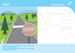
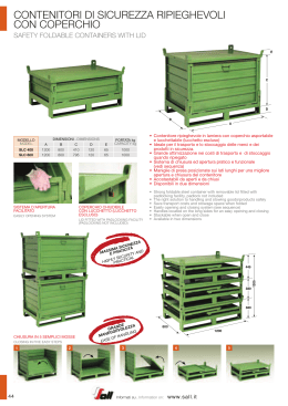
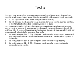
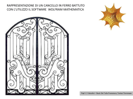
ITALIANO
PCM212
Centrale di automazione a 12V
per cancello ad ante
MANUALE UTENTE
Made in Italy
EMC 89/336 CEE
PCM212 - Manuale per l'utente
Norme generali per la sicurezza
!
!
!
!
!
!
!
!
!
!
!
!
!
Leggere attentamente le istruzioni prima di iniziare I'installazione del prodotto e conservarle per riferimenti futuri.
Installazione, collegamenti elettrici e regolazioni devono essere effettuati nell'osservanza delle norme di buona tecnica e
di sicurezza vigenti (EN12453).
HILTRON Srl non è responsabile dell'inosservanza della buona tecnica nella costruzione dei cancelli da motorizzare,
nonchè delle deformazioni che dovessero intervenire nell'utilizzo.
Questo prodotto è stato progettato e costruito esclusivamente' per I'utilizzo indicato in questa documentazione. Qualsiasi
altro utilizzo non espressamente indicato potrebbe pregiudicare I'integrità del prodotto e/o rappresentare fonte di
pericolo.
HILTRON Srl declina qualsiasi responsabilità derivata dall'uso improprio o diverso da quello per cui I'automatismo è
destinato.
Non utilizzare I'apparecchio in atmosfera esplosiva: presenza di gas o fumi infiammabili costituiscono un grave pericolo
per la sicurezza.
Prima di effettuare qualsiasi intervento sull'impianto togliere I'alimentazione elettrica.
Prevedere sulla rete d'alimentazione dell'automazione un interruttore onnipolare con distanza d'apertura dei contatti
uguale o superiore a 3 mm. In alternativa e consigliabile I'uso di un magnetotermico da 6A con interruzione onnipolare.
Verificare che a monte dell'impianto elettrico vi sia un interruttore differenziale con soglia da 0,03 A.
Verificare che I'impianto di terra sia realizzato a regola d'arte e collegarvi iI cancello. Collegare inoltre a terra il filo
Giallo/Verde dell'automatismo.
L'utente utilizzatore deve astenersi da qualsiasi tentativo di riparazione o d'intervento diretto e rivolgersi solo a personale
qualificato.
Per la manutenzione utilizzare esclusivamente parti originali CIA della HILTRON Srl. Non eseguire alcuna rnodifica sui
cornponenti facenti parte il sistema d'autornazione. I materiali dell'imballaggio (plastica, cartone, ecc.) non devono
essere lasciati alla portata dei bambini in quanto potenziali fonti di pericolo.
L'installatore deve fornire tutte le informazioni relative al funzionamento manuale del sistema in caso d'emergenza e
consegnare all'utente utilizzatore dell'impianto il
presente libretto d'avvertenze allegato al
prodotto.
L'automazione dispone di una sicurezza
antischiacciamento costituita da un controllo di
coppia che, se tarato correttamente, è
DICHIARAZIONE
DI CONFORMITA’
estremamente sicuro ed affidabile.
In accordo con la norma EN 45014 e guida ISO/IEC 22
In ogni caso HILTRON Srl prescrive sempre
I'installazione di altri dispositivi di sicurezza,
COSTRUTTORE: HiLTRON S.r.l.
tenendo in considerazione le normative in
INDIRIZZO: Via Caserta al Bravo, 218 - NAPOLI
vigore, I'ambiente di installazione, la logica di
funzionamento del sisterna, le dimensioni e il
PRODOTTO: KIT DI AUTOMAZIONE CANCELLO AD ANTE
peso della struttura da automatizzare.
MARCHIO: CIA
I dispositivi di sicurezza (es.: fotocellule, coste
pneumatiche, etc...) permettono di proteggere
CODICE PRODOTTO: KB312 - KB412
eventuali zone di schiacciamento,
Il prodotto sopra descritto risulta conforme ai requisiti prescritti dalle seguenti norme:
convogliamento ed in generale di pericolo,
dell'automazione. Per ogni irnpianto è
NORMA APPLICATA
TITOLO
indispensabile I'utilizzo di almeno una
EN50081-1 (1992)
NORMA GENERICA DI EMISSIONE
segnalazione luminosa (es.: art. LAMP12FG)
Classe della norma generica: domestico,
nonchè di una targa di segnalazione (es.: art.
commerciale ed industriale leggero.
TRG CIA) fissato adeguatamente alla struttura
EN50082-1 (1992)
NORMA GENERICA DI IMMUNITA’
del cancello.
Classe della norma generica: domestico,
HILTRON Srl declina ogni responsabilità ai fini
commerciale ed industriale leggero.
della sicurezza e del buon funzionamento
EN60335-1 (1996)
NORMA PER LA SICUREZZA DEGLI
dell'automazione nel caso in cui vengano
APPARECCHI ELETTRICI D'USO
DOMESTICO E SIMILARE
utilizzati componenti dell'impianto diversi da
quelli CIA (prodotti da HILTRON Srl).
La conformita' e' stata valutata sulla base di prove eseguite su campione e con allestimento che
®
!
!
!
!
PROGETTAZIONI E PRODUZIONI ELETTRONICHE
rispecchia la configurazione funzionale prevista per la sua utilizzazione allestita interamente con
prodotti CIA di produzione HiLTRON S.r.l. .
Napoli, 17 Marzo 2003
L’ AMMINISTRATORE DELEGATO
2
Indice
Indice
Capitolo 1 Introduzione
1.1
1.2
1.3
1.4
1.5
4
Composizione del kit.........................................................................................................4
Caratteristiche tecniche dei motori ...................................................................................5
Come funziona il kit ..........................................................................................................6
Comando di emergenza ...................................................................................................6
Norme applicate................................................................................................................6
Capitolo 2 Installazione del kit
7
2.1 Esempio di installazione dell’ impianto .............................................................................7
2.2 Montaggio supporti ...........................................................................................................8
2.2.1 Montaggio supporto posteriore (staffa “F”)...........................................................8
2.2.2 Tabella montaggio (staffa “F”) ..............................................................................9
2.2.3 Montaggio supporto anteriore (staffa “G”)..........................................................10
2.3 Descrizione della scheda ................................................................................................11
2.4 Descrizione della morsettiera .........................................................................................12
2.5 Collegamenti...................................................................................................................13
2.5.1 Rete di alimentazione, lampeggiatore e motoriduttori........................................13
2.5.2 Collegamento fotocellule a relè (FX40, FX55, ecc.) ..........................................14
2.5.3 Collegamento fotocellule con autodiagnosi (FX30) ...........................................14
2.5.4 Comandi, comandi timer, elettroserratura..........................................................15
2.5.5 Antenna con ricevitore VHF - BIRD ...................................................................16
2.5.6 Programmazione codice telecomando...............................................................16
2.6 Programmazione del decoder per radiocomando...........................................................17
Capitolo 3 Programmazione
18
3.1 Logica di funzionamento.................................................................................................18
3.1.1 Sfasamento anta di chiusura .............................................................................19
3.1.2 Funzione “colpo d’ariete” ...................................................................................19
3.1.3 Funzione “pre lampeggio” ..................................................................................19
3.1.4 Selezione fotocellule ..........................................................................................19
3.2 Regolazioni .....................................................................................................................19
3.3 Funzionamento con un solo motoriduttore .....................................................................19
Capitolo 4 Funzionamento
21
4.1 LEDs di controllo.............................................................................................................21
4.2 Logiche di funzionamento...............................................................................................22
4.2.1 Funzionamento AUTOMATICO condominiale....................................................22
4.2.2 Funzionamento AUTOMATICO..........................................................................22
4.2.3 Funzionamento PASSO-PASSO........................................................................23
4.2.4 Funzionamento PASSO-PASSO con STOP ......................................................23
Capitolo 5 Manutenzione
24
5.1 Cancello..........................................................................................................................24
5.2 Fusibili ...........................................................................................................................24
3
PCM212 - Manuale per l'utente
1
Introduzione
Gentile cliente,
desideriamo ringraziarla per aver acquistato un prodotto CIA. Le consigliamo di leggere
attentamente questo manuale, poichè sarà prezioso sia in fase d'installazione che di uso.
Quale cliente CIA lei ha il privilegio di accedere ad una serie di servizi, primo fra tutti
l'assistenza tecnica telefonica sui prodotti CIA.
1.1
Composizione del kit
KB312
Kit automazione per cancello ad ante (anta max 2,5m)
composto da:
n.2
n.1
n.1
n.1
n.1
n.2
n.1
n.1
MB312
PCM212
BIRD
TWIN
LAMP12FG
FX30
SC1
TRG
Motoriduttore 12V autobloccante per anta max 2,5m.
Centrale di automazione a 12V per cancello battente.
Antenna con ricevitore in VHF.
Radiocomando VHF bicanale.
Segnalatore 12Vca 15VA di colore giallo.
Coppia mini-fotocellule ad infrarossi con autodiagnosi
Selettore a chiave STOP - APRE/CHIUDE.
Targa di segnalazione “Cancello automatico”.
KB412
Kit automazione per cancello ad ante (anta max 3,5m)
composto da:
n.2
n.1
n.1
n.1
n.1
n.2
n.1
n.1
4
MB412
PCM212
BIRD
TWIN
LAMP12FG
FX30
SC1
TRG
Motoriduttore 12V autobloccante per anta max 3,5m.
Centrale di automazione a 12V per cancello battente.
Antenna con ricevitore in VHF.
Radiocomando VHF bicanale.
Segnalatore 12Vca 15VA di colore giallo.
Coppia mini-fotocellule ad infrarossi con autodiagnosi
Selettore a chiave STOP - APRE/CHIUDE.
Targa di segnalazione “Cancello automatico”.
Introduzione
1.2
!
!
Caratteristiche dei motoriduttori
Attuatore a vite trapezioidale a tre principi, mossa da un motoriduttore a vite senza fine
irreversibile provvisto di SISTEMA DI SBLOCCO DI EMERGENZA (CHMB in figura 01).
Possibilità di lavoro continuativo.
Figura 01
CHMB
Caratteristiche tecniche (MB312):
!
!
!
!
!
!
!
!
Alimentazione: 12Vcc
Corrente max: 8A
Lunghezza max dell'anta: 2,5m
Spinta massima: 150N
Velocità di movimento stelo: 1.5 cm/s
Corsa stelo: 300mm
Temperature di esercizio: -15°C ÷ +45°C
Grado protezione: IP44
Caratteristiche tecniche (MB412):
!
!
!
!
!
!
!
!
Alimentazione: 12Vcc
Corrente max: 8A
Lunghezza max dell'anta: 3,5m
Spinta massima: 150N
Velocità di movimento stelo: 1.5 cm/s
Corsa stelo: 400mm
Temperature di esercizio: -15°C ÷ +45°C
Grado protezione: IP44
5
PCM212 - Manuale per l'utente
1.3
Come funziona il kit
L’impulso inviato dal telecomando “C”
(TWIN) viene ricevuto dalla centrale “B”
(PCM212) che provvederà a fornire
l’energia ai motori “A” (MB312 o MB412)
per muovere le ante del cancello.
Un secondo impulso produrrà la
richiusura delle ante, oppure,
programmando opportunamente la
centrale si potranno richiudere
automaticamente.
Il lampeggiatore “E” (LAMP12FG)
indica attraverso due tipi di lampeggi che le
ante sono in movimento (lampeggio
veloce=apertura, lampeggio
lento=chiusura).
Figura 02
NOTA: Il sistema è stato progettato per durare negli anni e necessita di pochissima manutenzione.
Lavare saltuariamente gli attuatori con acqua e sapone.
Lo stelo dell’attuatore in acciaio inossidabile non deve MAI essere lubrificato.
NOTE DI SICUREZZA:
Il sistema è provvisto di una sicurezza elettronica antischiacciamento controllata da un microprocessore.
Per una corretta regolazione verificare il buon funzionamento dei cardini del cancello.
Si consiglia di applicare due coppie di fotocellule.Questi dispositivi provvederanno a bloccare le ante
qualora un oggetto venga ad interporsi alla loro corsa.
Si consiglia inoltre di attenersi alle normative inerenti l’automazione in essere nei vari paesi .
1.4
Comando di emergenza
Nel caso di mancato funzionamento si potrà aprire le ante agendo manualmente.
Inserire il chiavino di sblocco (CHMB) a ll’interno dell’ apposita feritoia triangolare posta sopra i motori
quindi ruotare fino al fermo in senso antiorario (vedi figura 01). I motori si sbloccheranno.
L’operazione inversa ripristinerà l’automatismo.
1.5
Norme applicate
L’apperecchiatura corrisponde alle direttive: CEE 89 /392; EN61000-3-2; EN61000-3-3; EN55014; ETS300
683 ENV 50141; 1-ETS300-220CEPT T/R 01-04;
Apparecchio di classe II.
CEE 72/23 EN 60335/1, EN60529/II, EN60034.
6
Installazione
2
Installazione del kit
M1
2.1
M2
M3
M4
Esempio d'installazione dell’impianto
9
11
10
2
3
6
7
1
8
4
5
1
PCM212
Centrale di automazione a 12V per cancello ad ante
2
FX30 (TX)
Fotocellula trasmittente di chiusura
3
FX30 (RX)
Fotocellula ricevente di chiusura
4
FX30 (TX)
Fotocellula trasmittente di apertura/chiusura
5
FX30 (RX)
Fotocellula ricevente di apertura/chiusura
6
Elettroserratura
7
MB312
Motoriduttore (2) 12V autobloccante per anta max 2,5m.
8
MB312
Motoriduttore (1) 12V autobloccante per anta max 2,5m.
9
SC1
Selettore a chiave STOP - APRE/CHIUDE.
10
LAMP12FG
Segnalatore 12Vca 15VA di colore giallo
11
BIRD
Antenna con ricevitore VHF
*
Figura 03
Il motoriduttore 1 è quello dell’anta che apre per prima ed ha l’elettroserratura.
7
PCM212 - Manuale per l'utente
2.2
Montaggio supporti
2.2.1 Montaggio supporto posteriore (staffa “F”)
Fissaggio a saldare
Fissaggio con tasselli
L
L
H
F
Figura 04
F
F
Figura 05
Figura 06
G
H
Figura 07
Procedere al montaggio della piastra regolabile “F” (tramite i perni “L”) ed al fissaggio della stessa al muro
(o al pilastrino del cancello).
Questa operazione è di estrema importanza in quanto, in base alle distanze A e B (vedi figura 09) si
modificheranno la velocita’ di apertura del cancello e la forza di spinta dell’attuatore.
Elementi fondamentali per effettuare questa scelta sono: 1. Dimensioni (peso/lunghezza) del cancello.
2. Misure del pilastro
Di seguito, troverete una tabella di misure per la determinazione del posizionamento della piastra F rispetto
all’asse di rotazione del cancello V(cardine).
KIT DI STAFFE E ACCESSORI PER INSTALLAZIONE MOTORIDUTTORI
Figura 08
8
Installazione
2.2.2 Tabella montaggio (staffa “F”)
Tramite la seguente tabella è possibile determinare angolo e velocità di apertura del cancello.
cm.
A: 8
A: 10
A: 12
A: 14
B: 8
16sec/97°
18sec/110°
21sec/118°
23sec/125° 23sec/130°
24sec/135° 26sec/137°
27sec/124° 28sec/115°
B: 10
18sec/98°
19sec/107°
22sec/114°
23sec/121° 25sec/127°
27sec/131° 27sec/125°
29sec/115° 31sec/108°
B: 12
20sec/98°
23sec/105°
24sec/112°
26sec/118° 27sec/124°
29sec/127° 30sec/120°
33sec/110° 34sec/104°
B: 14
21sec/95°
24sec/103° 25sec/108° 27sec/105° 28sec/120°
30sec/125°
32sec/111°
33sec/105°
35sec/99°
B: 16
23sec/94°
25sec/102° 28sec/108° 30sec/103° 31sec/118°
33sec/113°
34sec/102°
35sec/98°
37sec/94°
B: 18
26sec/94°
27sec/100° 29sec/106°
33sec/115°
34sec/105°
36sec/97°
36sec/93°
38sec/90°
B: 20
28sec/94°
30sec/100° 32sec/105° 34sec/109° 35sec/103°
37sec/96°
40sec/90°
B: 22
29sec/93°
33sec/99°
33sec/103° 34sec/106°
38sec/90°
B: 24
32sec/93°
34sec/99°
36sec/102°
B: 26
34sec/93°
36sec/98°
37sec/92°
B: 28
38sec/93°
32sec/111°
A: 16
37sec/95°
A: 18
A: 20
A: 22
A: 24
37sec/93°
Per ante di lunghezza superiore a 150 cm orientarsi su misure di “B” superiori a cm.10.
La misura “A” è tendezialmente ininfluente, la scelta quindi potrà essere determinata solamente dalle
necessità di ingombro derivanti dal tipo di pilastro.
Alcune misure standard consigliate (per attuatori 300 mm di corsa) sono:
Cancelli di lunghezza inferiore a cm. 150
Figura 09
A=10 cm / B= 10 cm.
Oltre i 150 cm.
A= 14 cm. / B= 12 cm.
V
Ricordarsi che maggiore è la misura di “B” più il
cancello si aprirà lentamente.
Attenzione: Potenza massima di spinta
autorizzata è di 150N.
Qualora per necessità particolari si dovessero
usare queste misure, è obbligatorio applicare una
coppia di fotocellule di sicurezza.
F
G
9
PCM212 - Manuale per l'utente
2.2.3 Montaggio supporto anteriore (staffa “G”)
Una volta effettuato il fissaggio della piastra “F” installare l’attuatore per mezzo del perno ”H”
(come in figura 07).
Chiudere (completamente) le ante del cancello, sbloccare l’attuatore con il chiavino (”I” in
fig.08), tirare lo stelo dell’attuatore alla massima estensione e dopo farlo rientrare di 5mm circa.
A questo punto, bloccare l’attuatore con il chiavino (”I”) quindi fissare la staffa (”G” in fig.08)
facendo attenzione che, l’attuatore sia perfettamente allo stesso livello delle staffe (come in
figura 10).
ATTENZIONE: E’ consigliabile di verificare la buona esecuzione del montaggio movimentando
manualmente le ante del cancello.
Figura 10
10
Installazione
2.3
Descrizione della scheda
2
10
1
8
7
Figura 11
11
12
3
4
5
9
6
14
15
13
16
F2
Fusibile alimentazione 8A 250V
10
JP1
Ponticello config. singolo motore
LED3 Led STOP
11
SW1
Dip-switch per la programmazione
4
LED4 Led fotocellula apertura/chiusura
12
T1
Trimmer regolazione durata pausa
5
LED5 Led fotocellule chiusura
13
12,5V
Alimentazione 12,5Vca max 8A
6
LED6 Led diagnosi microprocessore
14
M1
Morsettiera
7
P1
Pulsante apertura totale
o Autoapprendimento
15
M2
Morsettiera
16
M3
Morsettiera
8
P2
Pulsante apertura parziale
o Autoapprendimento
1
LED1 Led pulsante P1
9
2
LED2 Led pulsante P2
3
11
PCM212 - Manuale per l'utente
2.4
Descrizione della morsettiera
1
6
7
M1
11
M2
M1
1 - comune
2 - stop
3 - apertura totale (PULSE A)
4 - apertura parziale (PULSE B)
5 - negativo (mors. 2 BIRD)
6 - positivo (mors. 1 BIRD)
12
19
M3
COMANDI DI APERTURA
Ricevitore VHF con antenna BIRD
M2
7 - apertura/chiusura
8 - comune
9 - chiusura
CONTATTI FOTOCELLULE
(FX30 - FX40 - FX55)
10 - negativo 12Vcc
11 - positivo 12Vcc
ALIMENTAZIONE SERVIZI
12Vdc
M3
12 - 13 - alimen. motoriduttore 1
MOTORIDUTTORE 1
12Vdc 60W max
14 - 15 - alimen. motoriduttore 2
MOTORIDUTTORE 2
12Vdc 60W max
16 - 17 - alimen. LAMP12FG
18 - 19 - alimen. elettroserratura
12
LAMPEGGIATORE 12Vac 15W
ELETTROSERRATURA 12Vac 10W
Installazione
2.5
Collegamenti
2.5.1 Rete di alimentazione, lampeggiatore e motoriduttori
1
6
7
11
12
19
M1
MOTORIDUTTORE 1*
12Vdc 60W max
( 7 fig.03)
*
2x1mm
2x1,5mm
2x1,5mm
Alimentazione
12,5Vac - 8A max
M2
MOTORIDUTTORE 2
12Vdc 60W max
( 8 fig.03)
LAMP12FG
Lampeggiatore
12Vac 15Wmax
( 4 fig.03)
Il motoriduttore 1 è quello dell’anta che apre per prima ed ha l’elettroserratura.
13
PCM212 - Manuale per l'utente
2.5.2 Collegamento fotocellule a relè (FX40, FX55 ecc.)
1
SW1
6
7
11
ON
OFF
2B2
12V
+
-
+
Fotocellula chiusura
2B
12V
NC
RX
( 3 fig.3)
12V
(
+
-
2
TX
fig.3)
+
Fotocellula apertura/chiusura
12V
NC
RX
( 5 fig.3)
TX
( 4 fig.3)
2.5.3 Collegamento fotocellule con autodiagnosi (FX30)
1
SW1
6
7
11
ON
OFF
2B
2B
+
-
RX
( 3 fig.3)
14
+
-
Fotocellula
apertura
chiusura
(
2
TX
fig.3)
2B
2B
+
-
TX
( 4 fig.3)
Fotocellula
chiusura
+
-
RX
( 5 fig.3)
Installazione
2.5.4 Comandi, comandi timer, elettroserratura
1
6
19
Apertura
totale
Apertura
parziale
Pulsanti di comando opzionali
tramite relè (da citofono, etc.)
12Vca
2B
STOP
NC
Elettroserratura (
fig.3
6
)
NA
APRE
CHIUDE
4S
SC1 ( 9 )
fig.3
N.A.
Timer *
*
Per eventuali necessità di avere il cancello bloccato aperto in un certo orario (es. 7:00 ÷ 8:30 del mattino),
è possibile collegare un timer come mostrato sopra (par. 4.2.1).
All’ attivazione del timer (commutazione contatto da N.A. a N.C.), il cancello eseguirà un ciclo di apertura
e resterà aperto fino a quando il contatto timer è N.C.
15
PCM212 - Manuale per l'utente
2.5.5 Antenna con ricevitore VHF - BIRD
6
7
11
12
19
2x0.22mm
1
BIRD
ATTENZIONE: utilizzare un cavo schermato a due conduttori, tipo 2S, dedicato al collegamento
del solo ricevitore BIRD.
Non utilizzare due conduttori liberi di cavi già utilizzati per altre periferiche.
Si ricorda di prestare attenzione nel rispettare la polarità in fase di collegamento, e di
collegare il terminale schermato sul morsetto “2”.
2.5.6 Programmazione codice telecomando
Una volta inserito un codice casuale nel
telecomando (come da istruzioni allegate al TWIN
o BLACK) è necessario far acquisire alla centrale
tale codice, quindi seguire le istruzioni del
paragrafo successivo (2.6).
TWIN
BLACK
Per semplificare l’inserimento del codice nel telecomando, riportare il codice scelto nella tabella seguente:
1
2
3
4
5
6
7
8
9
10
11 12
P1 = ON
LED1
P2 = OFF
LED2
16
Installazione
2.6
Programmazione del decoder per radiocomando
Acquisizione con auto-apprendimento del codice del telecomando
!
!
!
!
Premere contemporaneamente i pulsanti P1-P2 (almeno 5 secondi) e rilasciare quando i due leds inizieranno a
lampeggiare
Premere il pulsante P1, lampeggerà solo il led "1”
Durante il lampeggio premere entro 5 secondi il pulsante "A" del telecomando per fare acquisire il proprio codice
Il led "1" emetterà una serie di lampeggi per indicare l'avvenuta acquisizione ed automaticamente si uscirà dalla
fase di programmazione
NOTA: Se nessun radiocomando viene attivato nell’arco di 10 secondi, la procedura ha termine senza programmare
alcun codice.
Per far acquisire il codice del canale "B" del telecomando, ripetere la procedura.
Visualizzazione del codice programmato
!
!
!
Premere contemporaneamente i pulsanti P1-P2 (max 3 secondi) e rilasciare quando i due leds relativi ai due
pulsanti si accenderanno fissi
Premendo il pulsante P1 verrà visualizzato il codice a 12 bit del canale "A" tramite una sequenza di lampeggi dei
due leds:
!
un lampeggio del led "1" indica dip switch ON
!
un lampeggio del led "2" indica dip switch OFF
Terminata la sequenza di lampeggi si uscirà automaticamente da questa fase di programmazione;
NOTA: Se nessun tasto viene attivato nell’arco di 5 secondi, la procedura ha termine senza visualizzare alcun codice.
Per visualizzare il codice relativo al canale "B" ripetere la procedura.
Tempo di pressione contemporanea dei pulsanti P1 e P2:
0 sec.
2 sec.
5 sec.
Stato dei LED
LED “1” e “2”
spenti
LED “1” e “2”
accesi fissi
LED “1” e “2”
lampeggianti
Funzione
Nessun effetto.
Rilasciando P1 e P2, si
entrerà in modalità di
visualizzazione del
codice.
Rilasciando P1 e P2, si
entrerà in modalità
autoapprendimento del
codice.
17
PCM212 - Manuale per l'utente
3
Programmazione
3.1
Logica di funzionamento
La centrale PCM212 può funzionare secondo quattro diverse logiche di funzionamento, descritte
dettagliatamente nel capitolo 4 “Funzionamento”; esse sono adattabili alle diverse esigenze dell’utente:
"
"
"
"
Funzionamento “Automatico Condominiale”
Funzionamento “Automatico”
Funzionamento “passo/passo con richiusura automatica”
Funzionamento “passo/passo con STOP”
E’ possibile programmare il tipo di funzionamento tramite i microinterruttori 1 e 2 del dip-switch (SW1)
(vedi par. 4.2 - Logiche di funzionamento).
SW1
Funzionamento Automatico
Condominiale
SW1
OFF
ON
SW2
OFF
OFF
SW1
Funzionamento Automatico
SW1
ON
ON
SW2
OFF
OFF
SW1
Funzionamento passo/passo
con richiusura automatica
SW1
OFF
ON
SW2
ON
OFF
SW1
Funzionamento passo/passo
con STOP
SW1
ON
ON
SW2
ON
OFF
Sfasamento
anta (1) di chiusura
8 secondi
4 secondi
SW3
ON
OFF
Funzione
“Colpo d’Ariete”
Attivato
Disattivato
SW4
ON
OFF
Attivato
Disattivato
SW5
ON
OFF
FX30 (autodiagnosi)
FX40 - FX55
SW6
ON
OFF
Funzione di
“Pre lampeggio”
Tipo fotocellula installata
18
SW1
ON
OFF
SW1
ON
OFF
SW1
ON
OFF
SW1
ON
OFF
Programmazione
3.1.1
Sfasameto anta di chiusura
E’ possibile variare il ritardo in chiusura dell’anta (1) (4 o 8 secondi) tramite la posizione del
microinterruttore 3 (ON= 8 secondi; OFF= 4 secondi)
3.1.2
Funzione “colpo d’ariete”
Il “Colpo d’ariete” serve a favorire lo sblocco dell’elettroserratura quando viene dato il comando di
apertura del cancello, ed è possibile attivarlo/disattivarlo tramite il microinterruttore 4.
ll motoriduttore (1), quello dell’anta che apre per prima e su cui è anche installata l’elettroserratura, viene
alimentato per qualche attimo in chiusura, e subito dopo comincia il suo normale moto di apertura.
3.1.3
Funzione “pre lampeggio”
La funzione di pre lampeggio attiva l’ accensione del lampeggiatore 2 secondi prima dell’ apertura del
cancello. E’ possibile attivarla/disattivarla tramite il microinterruttore 5.
3.1.4
Selezione fotocellule
E’ possibile selezionare, tramite il microinterruttore 6 il tipo di fotocellule che saranno installate.
Se sono del tipo “a rele” (FX40, FX55 ecc.), si dovrà posizionare il microinterruttore 6 su OFF, altrimenti
nel caso di utilizzo di fotocellule con autodiagnosi (FX30), il microinterruttore 6 dovrà essere posizionato su
ON.
3.2
Regolazioni
Dopo aver impostato i parametri della logica di funzionamento, se la centrale è stata programmata in
Funzionamento automatico, è necessario regolare il tempo di pausa che intercorre tra il termine dell'apertura
e l’inizio della chiusura del cancello.
E’ possibile effettuare questa regolazione, da minimo 2 secondi ad un massimo di 60 secondi, tramite il
Trimmer ”Pausa” (12 fig.11).
3.3
Funzionamento con un solo motoriduttore
E’ possibile disattivare il controllo del motore 2 nel caso in cui la centrale PCM212 sia
destinata ad automatizzare un cancello ad anta singola. Tale impostazione è determinata dal
jumper JP1:
!
!
JP1 ON (default)
JP1 OFF
Controllo dei due motoriduttori.
Controllo del solo motoriduttore 1.
Non sarà necessario regolare lo sfasamento
19
PCM212 - Manuale per l'utente
NOTA IMPORTANTE AL COLLAUDO:
Alla fine dell'installazione, posizionare le due ante del cancello più o meno a metà corsa per poter
verificare il senso di rotazione dei due motori.
Al primo impulso di avviamento si dovrebbero aprire entrambe le ante del cancello, nel caso che questo
non avvenga, invertire i fili relativi al motore che andava in chiusura.
Messi in fase i due motori inviare un impulso alla centrale ed avviare il ciclo, in questa fase la centrale
autoapprenderà in maniera autonoma l'apertura, la chiusura, ed il rallentamento di circa 3 secondi che si
attiva sia alla partenza che all'arrivo delle ante, questo per evitare gli inutili colpi che creano rumori e che
potrebbero danneggiare l'intera struttura del cancello e dei motori.
Dopo il primo ciclo di apprendimento, a cancello chiuso, un nuovo impulso avvierà l'anta N°1, dopo circa
3 secondi di sfasamento partirà l'anta N°2, aperte totalmente e trascorso il tempo di pausa (se programmato)
per la chiusura partirà prima l'anta N°2 e dopo il tempo di sfasamento di 4 o 8 secondi (par 3.1.1) partirà l'anta
N°1.
NOTA DI SICUREZZA:
Oltre alle due coppie di fotocellule che proteggono, in manovra del cancello, eventuali danni alle auto, la
centrale controlla la corrente assorbita dai singoli motori e questo consente che nel caso in cui una delle due
ante trovi un ostacolo, la stessa si arresta immediatamente.
Rimosso l’ostacolo il cancello ricomincerà a funzionare automaticamente senza dover intervenire
manualmente.
20
Funzionamento
4
Funzionamento
4.1
LEDs di controllo
Sono presenti 6 LEDs sul circuito per facilitare il controllo del funzionamento delle
apparecchiature periferiche e degli impulsi di comando:
LED 1
LED 2
LED 3
LED 4
LED 5
LED 6
verde
verde
giallo
rosso
rosso
verde
Controllo apertura parziale (solo l’anta del motoriduttore 1)
Controllo impulso A (apertura totale)
Controllo impulso STOP
Controllo stato delle fotocellule di apertura/chiusura
Controllo stato delle fotocellule di chiusura
Controllo anomalie centrale
Lampeggiante
Fisso acceso oppure fisso spento
funzionamento normale della centrale
funzionamento anomalo della centrale
FUNZIONAMENTO DEI LEDs
LED
ACCESO
1
Pulse B apertura parziale
2
Pulse A apertura totale
SPENTO
A riposo
3
4
Impulso STOP
Funzionamento normale
Fotocellula di apertura/chiusura non allineata
5
Fotocellula di chiusura non allineata
LED
Lampeggiante
Fisso acceso oppure fisso spento
6
Funzionamento normale
Funzionamento anomalo
1
2
3
4
5
6
21
PCM212 - Manuale per l'utente
4.2
Logiche di funzionamento
4.2.1
Funzionamento AUTOMATICO condominiale
(SW1=OFF - SW2=OFF)
Un impulso esegue : apertura , pausa , richiusura automatica .
Durante la fase di apertura vengono ignorati eventuali impulsi .
Un contatto fisso chiuso su IMPULSO A ( funzione orologio ) apre il cancello fino alla pausa e lascia il
cancello aperto sino alla riapertura del contatto.
SW1
ON
OFF
IMPULSI DI COMANDO
STATO DEL
CANCELLO
IMPULSO A
IMPULSO B
STOP
CHIUSO
Apre 2 ante e richiude
dopo il tempo di pausa
Apre 1 anta e richiude
dopo il tempo di pausa
Ignora impulsi A e B
impedendo l’apertura
IN
APERTURA
Nessun Effetto
Ignora impulsi A e B
impedendo l’apertura
Nessun Effetto
Blocca
funzionamento e
riprende al
disimpegno
Nessun effetto se il
ciclo di apertura è
iniziato con PULSE A
Apre seconda anta se
il ciclo di apertura è
iniziato con PULSE B
Nessun Effetto
APERTO IN
PAUSA
Impedisce la richiusura ed alla fine della pausa
reintegra ulteriori 5 secondi sino al ripristino
IN CHIUSURA
Si arresta e riapre immediatamente
IN STOP
Riprende la funzione che era in esecuzione
prima dello STOP ( chiusura o apertura )
4.2.2
FOTOCELLULA FOTOCELLULA
CHIUDE
APRE/CHIUDE
Blocca
funzionamento e
va in STOP
Impedisce la richiusura ed alla fine della pausa
reintegra ulteriori 5 secondi sino al ripristino
Blocca il funzionamento Blocca il funzionamento
e riapre il cancello
e riprende al
immediatamente
disimpegno
Ignora impulsi A e B
impedendo la riapertura o la richiusura
Funzionamento AUTOMATICO ( SW1=ON - SW2=OFF)
SW1
ON
Un impulso esegue : apertura , pausa , richiusura automatica .
Durante la fase di apertura o chiusura , eventuali impulsi , arrestano ed invertono immediatamente il
moto del cancello .
Durante la fase di pausa, eventuali impulsi richiudono immediatamente il cancello.
OFF
IMPULSI DI COMANDO
STATO DEL
CANCELLO
IMPULSO A
IMPULSO B
STOP
CHIUSO
Apre 2 ante e richiude
dopo il tempo di pausa
Apre 1 anta e richiude
dopo il tempo di pausa
Ignora impulsi A e B
impedendo l’apertura
IN
APERTURA
Si arresta e richiude
immediatamente
APERTO IN
PAUSA
Richiude il cancello immediatamente
IN CHIUSURA
Si arresta e riapre immediatamente
IN STOP
Riprende la funzione che era in esecuzione
prima dello STOP
( chiusura o apertura )
22
FOTOCELLULA FOTOCELLULA
CHIUDE
APRE/CHIUDE
Blocca
funzionamento e va
in STOP
Nessun Effetto
Ignora impulsi A e B
impedendo l’apertura
Nessun Effetto
Blocca
funzionamento e
riprende al
disimpegno
Impedisce la richiusura ed alla fine della pausa
reintegra ulteriori 5 secondi sino al ripristino
Blocca il funzionamento Blocca il funzionamento
e riapre il cancello
e riprende al
immediatamente
disimpegno
Ignora impulsi A e B
impedendo la riapertura o la richiusura
Funzionamento
4.2.3
Funzionamento PASSO PASSO con richiusura automatica (SW1=OFF- SW2=ON)
Un impulso esegue : apertura , pausa , richiusura automatica .
Durante la fase di apertura o chiusura , eventuali impulsi , arrestano il cancello portandolo nella condizione di STOP .
Durante la fase di pausa , eventuali impulsi richiudono immediatamente il cancello .
SW1
ON
OFF
IMPULSI DI COMANDO
STATO DEL
CANCELLO
IMPULSO A
IMPULSO B
STOP
CHIUSO
Apre 2 ante e richiude
dopo il tempo di pausa
Apre 1 anta e richiude
dopo il tempo di pausa
Ignora impulsi A e B
impedendo l’apertura
IN
APERTURA
Si arresta e solo ad un successivo impulso
richiude
APERTO IN
PAUSA
Richiude il cancello immediatamente
FOTOCELLULA FOTOCELLULA
CHIUDE
APRE/CHIUDE
Blocca
funzionamento e va
in STOP
4.2.4
Ignora impulsi A e B
impedendo l’apertura
Nessun Effetto
Blocca funzionamento e
riprende al disimpegno
Impedisce la richiusura ed alla fine della pausa
reintegra ulteriori 5 secondi sino al ripristino
Blocca il
funzionamento e riapre Blocca il funzionamento
e riprende al
il cancello
disimpegno
immediatamente
IN CHIUSURA Si arresta e solo ad un successivo impulso riapre
IN STOP
Nessun Effetto
Riprende la funzione che era in esecuzione
prima dello STOP
( chiusura o apertura )
Ignora impulsi A e B
impedendo la riapertura o la richiusura
Funzionamento PASSO PASSO manuale (SW1=ON - SW2=ON)
SW1
ON
Un impulso apre ; l'impulso successivo arresta ; l'impulso successivo chiude ; l'impulso successivo si
arresta ; l'impulso successivo apre e così via .
OFF
IMPULSI DI COMANDO
STATO DEL
CANCELLO
IMPULSO A
IMPULSO B
STOP
CHIUSO
Apre 2 ante e si
arresta al termine
dell'apertura
Apre 1 anta e si
arresta al termine
dell'apertura
Ignora impulsi A e B
impedendo l’apertura
IN
APERTURA
Si arresta e solo ad un successivo impulso
richiude
ARRESTO
Inverte il movimento del motore
IN CHIUSURA Si arresta e solo ad un successivo impulso riapre
IN STOP
Riprende la funzione che era in esecuzione
prima dello STOP
( chiusura o apertura )
FOTOCELLULA FOTOCELLULA
CHIUDE
APRE/CHIUDE
Blocca
funzionamento e va
in STOP
Nessun Effetto
Ignora impulsi A e B
impedendo l’apertura
Nessun Effetto
Blocca funzionamento e
riprende al disimpegno
Ignora impulsi A e B bloccando ogni movimento
Blocca il funzionamento Blocca il funzionamento
e riapre il cancello
e riprende al
immediatamente
disimpegno
Ignora impulsi A e B
impedendo la riapertura o la richiusura
23
PCM212 - Manuale per l'utente
5
Manutenzione
5.1
Cancello
Eseguire controlli periodici della struttura del cancello ed in particolare verificare la perfetta
condizione delle cerniere e delle altre parti meccaniche soggette ad usura.
5.2
Fusibili
F1
1A 250V
Fusibile RETE
Questo fusibile protegge contro eventuali
sovraccarichi del trasformatore della
centrale.
F2
8A 250V
Fusibile alimen. scheda
Questo fusibile protegge da eventuali
cortocircuiti derivanti dalla scheda centrale.
24
423ADT-1.00
ENGLISH
PCM212
12V automation central unit
for winging gate
USER MANUAL
Made in Italy
EMC 89/336 CEE
PCM212 - User’s manual
Important Safeguards
!
!
!
!
!
!
!
!
!
!
!
!
!
!
!
Please read this manual thoroughly before installation and keep it for future reference.
Installation, electrical connections and adjustements must comply with technical and safety standards in
force.(EN12453).
HILTRON Srl cannot be held responsible for failure to observe technical standards in the construction of gates, or for any
deformation of gates which may occur during use.
This product has been designed and manufactured only for the use stated in this manual. Any other use not expressly set
forth will affect the reliability of the product and/or could be source of hazard.
HILTRON Srl cannot be held responsible for any damage caused by improper use or different from the use for wich the
autamtion system is destined to.
Do not use this device in areas subject to explosion: the presence of flammable gas or fumes is a serious hazard.
Before carrying out any operations, turn off the system’s main switch.
An omnipower switch shall be provided for the installation with an opening distance of the contacts of 3 mm or more.
Alternativel, use a 6A thermomagnetic breaker with a multi-pole switching.
Ensure that there is a differential switch up-line of the electrical system, with a trip threshold of 0.03A.
Check that the earthing plant is in perfect condition and connect it to the metallic parts. Also earth the Yellow/Green wire of
the operator.
The end-user must avoid any attempt to repair or adjust the automation personally. These operations must be carried out
only by qualified personnel.
For maintenance operations, use only CIA original spare parts produced by HILTRON Srl. Do not carry out any
modifications to automation components. Packaging materials (plastic, cardboard, etc.) are a potential hazard and must
be kept out of reach of children.
The installer must supply all informations regarding manual operation of the system in the event of an emergency and
provide the end-user with this manual attached to the product.
The automation is fitted with an anti-crush safety system that is a torque control device.
In any case, HILTRON Srl suggests the
installation of others safety devices, in
accordance with standards in force, system
operating logic and weight and dimension of the
PROGETTAZIONI E PRODUZIONI ELETTRONICHE
gate.
The safety devices (i.e.: photocells, pneumatic
DECLARATION
OF CONFORMITY
edges, etc...) protect areas wherethere is a
According to the EN 45014 standard, guide ISO/IEC 22
mechanical movement hazard (i.e.: crushing,
entrapment and cutting).
Each installation must be fitted with at least one
CONSTRUCTOR: HiLTRON S.r.l.
flashing light (i.e.: item LAMP12FG) or with at
ADDRESS: Via Caserta al Bravo, 218 - 80144 - NAPOLI
signalling plate (i.e.: item TRG CIA) fixed to the
gate.
PRODUCT: PCM212 - AUTOMATION KIT FOR WINGING GATE
HILTRON Srl cannot be held responsible
THE PRODUCTS RESULT CONFORM TO THE FOLLOWING STANDARDS
regarding safety and correct operation of the
REQUIREMENTDS:
automation in the event that parts other than CIA
original parts (produced by HILTRON Srl).
®
!
!
!
STND SPECIFICATION
TITLE
EN50081-1
EMISSION STND
Part 1: residential,commercial and light industry.
EN50082-1
IMMUNITY STND
Part 1: residential,commercial and light industry.
EN60335-1
SAFETY OF HOUSEHOLD AND
SIMILAR ELECTRICAL
APPLIANCES
CONFORMITY WAS BASED ON EMC PERFORMANCE TESTS CONDUCTED ON SAMPLE
RUNNING IN THE DESIGNED WORKING CONDITIONS AS FOR ITS FUNCTIONAL
PROJECT.
Naples 17 March 2003
2
COMPANY MANAGEMENT
Contents
Contents
Chapter 1
1.1
1.2
1.3
1.4
1.5
Introduction
4
KB312 and KB412 Automation kits ...................................................................................4
Geared Motors Technical Features ...................................................................................5
Kit Operation .....................................................................................................................6
Emergency Control ...........................................................................................................6
Conformity ........................................................................................................................6
Capitolo 2 Kit Installation
7
2.1 Example of in stallation.....................................................................................................7
2.2 Brackets Installation..........................................................................................................8
2.2.1 Rear Bracket Installation (“F”)..............................................................................8
2.2.2 Assembling Table (bracket “F”) ............................................................................9
2.2.3 Front Bracket Installation (bracket “G”) ..............................................................10
2.3 Board Description ...........................................................................................................11
2.4 Terminal Board Description.............................................................................................12
2.5 Connections....................................................................................................................13
2.5.1 Operating Voltage, Flasher and Geared Motors ................................................13
2.5.2 Relay Photocells Connection (FX40, FX55, ecc.)..............................................14
2.5.3 Photocells with Auto-Diagnosis Connection (FX30)...........................................14
2.5.4 Controls, Timer, Electric Lock ............................................................................15
2.5.5 BIRD - Antenna with VHF receiver ....................................................................16
2.5.6 Remote-control Code Programming ..................................................................16
2.6 Decoder of Remote-control Programming ......................................................................17
Capitolo 3 Programming
18
3.1 Operation Logic ..............................................................................................................18
3.1.1 Closing Wing Timing ..........................................................................................19
3.1.2 “Impact” Function ...............................................................................................19
3.1.3 “Pre flashing” Function.......................................................................................19
3.1.4 Photocells Selection...........................................................................................19
3.2 Adjustement....................................................................................................................19
3.3 Operation by One Geared Motor ....................................................................................19
Capitolo 4 Operation
21
4.1 Control LEDs ..................................................................................................................21
4.2 Operating Logics.............................................................................................................22
4.2.1 “AUTOMATIC” Park Operation...........................................................................22
4.2.2 “AUTOMATIC” Operation ...................................................................................22
4.2.3 “STEP-by-STEP” Operation...............................................................................23
4.2.4 “STEP-by-STEP with STOP” Operation.............................................................23
Capitolo 5 Maintenance
24
5.1 Gate
...........................................................................................................................24
5.2 Fuses ...........................................................................................................................24
3
PCM212 - User’s manual
1
Introduction
Dear Customer,
Thanks to have bought a CIA product. Please read this manual thoroughly before use and
during the installation. Keep it handy for future reference.
As CIA customer, you can use a series of services, such as the telephone technical
assistance on the CIA products.
1.1
KB312 and KB412 Automation kits
KB312
Automation Kit for winging gate (max 2,5m wing)
includes:
n.2
n.1
n.1
n.1
n.1
n.2
n.1
n.1
MB312
PCM212
BIRD
TWIN
LAMP12FG
FX30
SC1
TRG
12V Auto-Locking Geared-Motor for 2,5m wing.
12V Automation Central Unit for winging gate.
Antenna with VHF receiver.
VHF twin channel radio-control.
12Vdc Yellow Electronic Flasher.
Infrared Mini Photocells with autodiagnosis function
Key Selector STOP - OPEN/CLOSE type.
“AUTOMATIC GATE” Signalling Plate.
KB412
Automation Kit for winging gate (max 3,5m wing)
includes:
n.2
n.1
n.1
n.1
n.1
n.2
n.1
n.1
4
MB412
PCM212
BIRD
TWIN
LAMP12FG
FX30
SC1
TRG
12V Auto-Locking Geared-Motor for 3,5m wing.
12V Automation Central Unit for winging gate.
Antenna with VHF receiver.
VHF twin channel radio-control.
12Vdc Yellow Electronic Flasher.
Infrared Mini Photocells with autodiagnosis function
Key Selector STOP - OPEN/CLOSE type.
Targa di segnalazione “Cancello automatico”.
Introduction
1.2
!
!
Geared Motors Technical Features
Actuator provided with triple trapezoidal screw, driven by a irreversible worm screw gear motor
with EMERGENCY UNLOCK SYSTEM (figure 1: CHMB).
Possibility of continuos work.
Figure 01
CHMB
Technical Features (MB312):
!
!
!
!
!
!
!
!
Operating Voltage: 12Vdc
Max Current: 8A
Max Hing Lenght: 2,5m
Maximum Thrust: 150N
Piston Rod Speed: 1.5 cm/s
Rod Max Lenght: 300mm
Operating Temperatures: -15°C ÷ +45°C
Protection Degree: IP44
Technical Features (MB412):
!
!
!
!
!
!
!
!
Operating Voltage: 12Vdc
Max Current: 8A
Max Hing Lenght: 3,5m
Maximum Thrust: 150N
Piston Rod Speed: 1.5 cm/s
Rod Max Lenght: 400mm
Operating Temperatures: -15°C ÷ +45°C
Protection Degree: IP44
5
PCM212 - User’s manual
1.3
Kit Operation
The Remote-control “C” (TWIN)
transmits a pulse to the Central Unit “B”
(PCM212). which drives the wings of the
gate through the geared motors “A”
(MB312 o MB412).
A second pulse allows to close the
gate, or, if enabled, to close automatically
the wings.
The Electronic Flasher “E”
(LAMP12FG) signals through two different
flashings that the wings are in movement
(fast flashing=gate opening, slow
flashing=gate closing).
Figure 02
NOTE: The system is projected to last long and it needs very little maintenance.
Occasionally, clean the actuators using water and cleansing.
Do not lubricate the rod of the actuator made in stainless steel.
SAFETY STANDARDS:
The system is supplied with Anti-Crushing electronic safety device controlled by a built-in microprocessor.
For a proper adjustement, check the pivots of the gate.
We suggest you to install two couple of photocells, these devices allow to stop the wings in case of
obstacle.
We suggest you to conform to the standards in force in your Country.
1.4
Emergency Control
In the event of malfunction or power failure, the gate can be open manually.
To unlock the geared motors, insert the key (CHMB) into the triangular slit on the geared motors,and rotate
it CCW (see figure 1) up to the stop.
The contrary operation allows to reset the automatism.
1.5
Conformity
The device meets the following standards: CEE 89 /392; EN61000-3-2; EN61000-3-3; EN55014; ETS300
683 ENV 50141; 1-ETS300-220CEPT T/R 01-04;
Device of class II.
CEE 72/23 EN 60335/1, EN60529/II, EN60034.
6
Installation
2
Installation of Kit
M1
2.1
M2
M3
M4
Example of Installation
9
11
10
2
3
6
7
4
5
1
PCM212
12V Automation Central Unit for winging gate.
2
FX30 (TX)
Closing transmitting photocell.
3
FX30 (RX)
Closing receiving photocell.
4
FX30 (TX)
Closing/opening transmitting photocell.
5
FX30 (RX)
Closing/opening receiving photocell.
6
Electric Lock
7
MB312
12V Autolocking Geared Motor (2) for 2,5m wing.
8
MB312
2V Autolocking Geared Motor (1) for 2,5m wing.
9
SC1
Key Selector STOP - OPEN/CLOSE type.
10
LAMP12FG
12Vcc Yellow Electronic Flasher.
11
BIRD
Antenna with VHF receiver.
*
1
8
Figure 03
The Geared Motor 1 controls the wing will open first and where is installed the electric lock.
7
PCM212 - User’s manual
2.2
Bracket Installation
2.2.1 Rear Bracket Installation (“F”)
Fixing by welding
Fixing through screw anchors
L
L
H
F
Figure 04
F
F
Figure 05
Figure 06
G
H
Figure 07
Fit the adjustable plate “F” (through the pivots “L”) and fix it at the wall (or at the gate post).
This is a very important operation because you can modify the opening gate speed and the thrust force
according to A and B distance (see figure 9).
To choose the distance, you must consider:
1.
2.
Gate Dimensions (weight/lenght).
Gate Post Measures
The table below lists the measures to place the F plate according to the spin axis of the gate V (pivots).
BRACKET AND ACCESSORIES KIT FOR ACTUATORS INSTALLATION
Figure 08
8
Installation
2.2.2 Assembling Table (bracket “F”)
Use the following table to establish angle and speed gate opening.
cm.
A: 8
A: 10
A: 12
A: 14
B: 8
16sec/97°
18sec/110°
21sec/118°
23sec/125° 23sec/130°
24sec/135° 26sec/137°
27sec/124° 28sec/115°
B: 10
18sec/98°
19sec/107°
22sec/114°
23sec/121° 25sec/127°
27sec/131° 27sec/125°
29sec/115° 31sec/108°
B: 12
20sec/98°
23sec/105°
24sec/112°
26sec/118° 27sec/124°
29sec/127° 30sec/120°
33sec/110° 34sec/104°
B: 14
21sec/95°
24sec/103° 25sec/108° 27sec/105° 28sec/120°
30sec/125°
32sec/111°
33sec/105°
35sec/99°
B: 16
23sec/94°
25sec/102° 28sec/108° 30sec/103° 31sec/118°
33sec/113°
34sec/102°
35sec/98°
37sec/94°
B: 18
26sec/94°
27sec/100° 29sec/106°
33sec/115°
34sec/105°
36sec/97°
36sec/93°
38sec/90°
B: 20
28sec/94°
30sec/100° 32sec/105° 34sec/109° 35sec/103°
37sec/96°
40sec/90°
B: 22
29sec/93°
33sec/99°
33sec/103° 34sec/106°
38sec/90°
B: 24
32sec/93°
34sec/99°
36sec/102°
B: 26
34sec/93°
36sec/98°
37sec/92°
B: 28
38sec/93°
32sec/111°
A: 16
37sec/95°
A: 18
A: 20
A: 22
A: 24
37sec/93°
If the lenght of the wing is more than 150cm, use the measures “B” over 10cm.
The measure “A” is not so important measure, so choose it in according with the post measure.
For 300mm actuators stroke, suggested default measures are:
Lenght Gate under 150cm:
Figure 09
A=10 cm / B= 10 cm.
Over 150 cm:
A= 14 cm. / B= 12 cm.
V
The more measure “B” is bigger, the more the
gate opening will be slow.
Warning: Max Thrust is 150N.
F
G
9
PCM212 - User’s manual
2.2.3 Front Bracket Installation (“G”)
After to have fixed “F” plate, install the actuator through the “H” pivot (see figure 07).
Completely close the wings of the gate, and unblock the actuator by the key (”I” in fig.08), pull
the rod of the actuator to the maximum extension and after re-enter its of 5mm approximately.
At this point, block the actuator by the key (”I” in fig.08) therefore fix the bracket (”G” in fig.08)
making attention that, the actuator is perfectly to the same level of the brackets (like fig.10).
WARNING: It’s suggested to check the correct installation and assembling of the automation
system, moving manually the wings of the gate.
Figure 10
10
Installation
2.3
Board Description
2
10
1
8
7
Figure 11
11
12
3
4
5
9
6
14
15
13
16
F2
8A 250V Power Supply Fuse
10
JP1
Jumper One Motor Configuration
LED3 STOP LED
11
SW1
Dip-switch for Programming
4
LED4 Opening/Closing Photocell LED
12
T1
Pause Trimmer
5
LED5 Closing Photocell LED
13
12,5V
12,5Vac max 8A Power supply
6
LED6 Microprocessor Diagnosis LED
14
M1
Terminal Board
7
P1
Total Opening Button
or Auto-acquisition
15
M2
Terminal Board
16
M3
Terminal Board
8
P2
Partial Opening Button
or Auto-acquisition
1
LED1 P1 Button LED
9
2
LED2 P2 Button LED
3
11
PCM212 - User’s manual
2.4
Terminal Board Description
1
6
7
M1
11
M2
M1
1 - common
2 - stop
3 - total opening (PULSE A)
4 - single section opening (PULSE B)
5 - negative (terminal 2 BIRD)
6 - positive (terminal 1 BIRD)
12
19
M3
OPENING CONTROLS
Receiver VHF with antenna BIRD
M2
7 - opening/closing
8 - common
9 - closing
PHOTOCELLS CONTACTS
(FX30 - FX40 - FX55)
10 - negative 12Vdc
11 - positive 12Vdc
SERVICES POWER SUPPLY
12Vdc
M3
12
12 - 13 - geared motor 1 power supply
GEARED MOTOR 1
12Vdc 60W max
14 - 15 - geared motor 2 power supply
GEARED MOTOR 2
12Vdc 60W max
16 - 17 - LAMP12FG power supply
FLASHER 12Vac 15W
18 - 19 - electric lock power supply
LOCK 12Vac 10W
Installation
2.5
Connections
2.5.1 Operating Voltage, Flasher and Geared Motors
1
6
7
11
12
19
M1
GEARED MOTOR 1*
12Vdc 60W max
( 7 fig.03)
*
2x1mm
2x1,5mm
2x1,5mm
Alimentazione
12,5Vac - 8A max
M2
GEARED MOTOR 2
12Vdc 60W max
( 8 fig.03)
LAMP12FG
Flasher
12Vac 15Wmax
( 4 fig.03)
The Geared Motor 1 controls the wing will open first and where is installed the electric lock.
13
PCM212 - User’s manual
2.5.2 Relay Photocells Connection (FX40, FX55 etc.)
1
SW1
6
7
11
ON
OFF
2B2
12V
+
-
+
Closing Photocell
2B
12V
NC
RX
( 3 fig.3)
12V
(
+
-
2
TX
fig.3)
+
Opening/Closing Photocell
12V
NC
RX
( 5 fig.3)
TX
( 4 fig.3)
2.5.3 Photocells with Autodiagnosis Connection (FX30)
1
SW1
6
7
11
ON
OFF
2B
2B
+
-
RX
( 3 fig.3)
14
+
-
Opening/
Closing
Photocell
(
2
TX
fig.3)
2B
2B
+
-
TX
( 4 fig.3)
Closing
Photocell
+
-
RX
( 5 fig.3)
Installation
2.5.4 Controls, Timer, Electric Lock
1
6
19
Total
Opening
Partial
Opening
Optional Control Button
by relay (interphone, etc.)
12Vca
2B
STOP
NC
Electric Lock (
fig.3
6
)
NA
OPEN
CLOSE
4S
SC1 ( 9 )
fig.3
N.O.
Timer *
It is possible setting the opening of the gate by a timer (par.4.2.1)
i.e.: you can stop the opening of the gate from 7:00a.m. to 8:00a.m.
When the timer is activated (relay contact from N.O. to N.C.), the opening of the gate will stop
timer contact is N.C.
up to the
15
PCM212 - User’s manual
2.5.5 BIRD - Antenna with VHF Receiver
6
7
11
12
19
2x1mm
1
BIRD
WARNING: Use a shielded cable with two wires, 2S type, only for the connection of BIRD
receiver.
Do not use free wire of a cables used for another devices.
We rember you to look out the polarity during the connection procedure, and to connect the
shielded pin on terminal “2”.
2.5.6 Remote-control Code Programming
Enter a random code in the remote control (see
the instructions attached to TWIN or BLACK
product); follow the instruction in the next
paragraph (2.6) to encode the central unit with the
same code.
TWIN
BLACK
To simplify the entering of the code in the remote control, use the following table:
1
2
3
4
5
6
7
8
9
10
11 12
P1 = ON
LED1
P2 = OFF
LED2
16
Installation
2.6
Decoder of Remote-control Programming
Auto-Acquisition of Remote-Control Code
!
!
!
!
Keep down P1-P2 buttons (for 5 seconds) and release when the LEDs start to blink.
Press P1 button,only LED "1” blinks.
During the blinking, press "A" button of the remote-control to far acquisire the code
The LED "1" utters a sequence of blinkings to indicate that the code has been acquisito and to exit automatically
to the programming mode.
NOTE: If no remote- control is activated in 10 seconds, the produre is stopped and no code will be programmed.
For the acquisition of the code on the channel "B" from the remote-control, repeat the procedure.
Code Display
!
!
!
Keep down P1-P2 buttons (for 3 seconds) and release when the LEDs of the buttons light.
Pressing P1 button to display the 12-bit code of the channel "A" by a sequence of blinkings of the two LEDs:
!
one blink of the LED "1" for dip switch ON
!
one blink of the LED "2" for dip switch OFF
After the sequence of blinkings you will exit automatically to theprogramming mode;
NOTE: If no buttons is pressed in 5 seconds, the produre is stopped and no code will be displayed.
To display the code of the channel "B", repeat the procedure.
Time of simultaneous pressure of P1 e P2 buttons:
0 sec.
LEDs Status
Function
2 sec.
5 sec.
LED “1” and “2”
turn off
LED “1” and “2”
light
LED “1” and “2”
blink
No action.
Release P1 and P2
buttons to enter in Code
Display Mode.
Release P1 and P2
buttons to enter in
Auto-acquisition Code
Mode
17
PCM212 - User’s manual
3
Programming
3.1
Operating Logic
The PCM212 Central Unit can operate in 4 different operating logics that you can find in the chapter 4
“Operating Procedures”:
"
"
"
"
“Park Function” only automatic operating mode.
“Automatic” operating mode.
“Step-by-step with automatic closing” operating mode.
“Step-by-step with STOP” operating mode.
You can set an operating logic by a micro-switch 1 and 2 of dip-switch (SW1) (see par. 4.2 - Operating
Logics).
SW1
Park Function (only automatic mode)
SW1
OFF
ON
SW2
OFF
OFF
SW1
SW1
ON
“Automatic”
ON
SW2
OFF
OFF
SW1
“Step-by-step with automatic closing”
SW1
OFF
ON
SW2
ON
OFF
SW1
Step-by-step with STOP
SW1
ON
ON
SW2
ON
OFF
Closing Timing of wing (1)
“Impact” function
“Pre flashing” function
Type of Installed Photocell
18
8 secondi
4 secondi
SW3
ON
OFF
Attivato
Disattivato
SW4
ON
OFF
Attivato
Disattivato
SW5
ON
OFF
FX30 (autodiagnosi)
FX40 - FX55
SW6
ON
OFF
SW1
ON
OFF
SW1
ON
OFF
SW1
ON
OFF
SW1
ON
OFF
Programming
3.1.1
Closing Wing Timing
It is possible to delay the closing movement of the section (1) (4 or 8 seconds), through the position of
micro-switch 3 (ON= 8 seconds; OFF= 4 seconds)
3.1.2
“Impact” function
The “Impact” function allows to unlock the electronic lock when you use the remote control,and it is
possible to enable/disable it through the microswitch 4.
The geared motor (1), installed on the wing which will open first and where the electrical lock is installed,
will be powered for some seconds during the closing, after that it will start the regular opening procedure.
3.1.3
“Pre flashing” Function
This function alowws to enable the lighting of the flasher 2 seconds before the opening of the gate. It is
possible to enable/disable this function through the micro-switch 5.
3.1.4
Photocells Selection
This function allows to select the photocells which will be installed, by the micro-switch 6.
If the photocells are “relay photocells” (FX40, FX55 etc.), you must select OFF by the micro-switch 6, if the
photocells are photocells with auto-diagnosis (FX30), select ON by the micro-switch 6.
3.2
Adjustement
After to have programmed all “Operating Logics” parameters, if the central unit is setted in Automatic
Operation Mode, you must adjust the time of the “Pause” which is the time between the end of the gate opening
and the start of the gate closing.
It’s possible set this time from 2 seconds (min.) to 60 seconds (max.), through the Trimmer ”Pause”
( 12 fig.11).
3.3
Operating by one Geared Motor
It’s possible to disactivate the geared motor 2 in case of the PCM212 central unit must be
automize a one wing gate. To change this setting, you must disable the jumper JP1:
!
!
JP1 ON (default)
JP1 OFF
Two Geared Motors.
Only Gearde Motor 1. (no need the timing adjustment)
19
PCM212 - User’s manual
IMPORTANT NOTE FOR THE TEST:
At the end of installation, to position the two wings of the gate to the half of stroke more or less to verify the
sense of rotation of the two motors.
To the first impulse of starting either the wings of the gate should be opened,if this doesn’t happen, to
reverse the wires of the motor that went to the closing.
After the timing of the two motors, send a pulse to the central unit and start the sequence, during this
procedure the central unit will automatically provide the opening of the gate, the closing of the gate and the
delay of 3 sec. that is activated both during the opening and the closing of the wings. This delay allows to avoid
the loud hits which could damage the entire structure of the gate and the motors.
After the first sequence of autoacquisition, when the gate is closed, another pulse will allow to start the
wing 1, later around 3 seconds of timing the same pulse will open the wing 2. After the total opening of the
wings and after the pause time (if it’s enabled), the wings 2 will start first the colsing of the gate, later around 4
or 8 seconds of timing (par 3.1.1), the wing 1 will close.
SAFETY NOTE:
More than the two couple of photocells which allow to protect the cars from possible damages during the
movement of the gate, the central unit controls the current absorbed from the motors and this allows to stop
the movement of the wings if an obstacle is found.
Removed the obstacle, the gate will automatically start the operating procedures.
20
Operation
4
Operating Procedures
4.1
Control LEDs
On the board there are 6 LEDs to make easy the check of the other devices installed and of
the pulses:
LED 1
LED 2
LED 3
LED 4
LED 5
LED 6
green
green
yellow
red
red
green
Partial Opening Check (only the wing of the motor 1)
Pulse A Check (Total Opening)
STOP Pulse Check
Opening/Closing Photocells Status Check
Closing Photocells Status Check
Central Unit Anomalies Check
Blinking
Fixed turn on/off
Proper Operation of the Central Unit
Anomalies in the Central Unit Operation
LEDs
LEDs
ON
1
Pulse B - Partial Opening
2
Pulse A - Total Opening
OFF
Command Deactivated
3
4
STOP Pulse
Regular Operation
Opening/Closing Photocells don’t aligned
5
Closing Photocells don’t aligned
LED
BLinking
Fixed turn on/off
6
Proper Operation
Anomalous Operation
1
2
3
4
5
6
21
PCM212 - User’s manual
4.2
Operating Logic
4.2.1
AUTOMATIC Parking Function
(SW1=OFF - SW2=OFF)
One pulse allows :opening , pause , automatic closing .
During the opening operation others pulses will be ignored.
A fixed pulse ( clock function ) allow to open the gate up to the pause and the gate remains opened.
SW1
ON
OFF
PULSES
GATE
STATUS
PULSE A
PULSE B
STOP
CLOSE
Opens two wings and
they are closed after
the pause time.
Opens one wing and
it is closed after the
pause time.
Ignores the pulse A
and B and stops the
closing
OPENING
No Effect
OPEN
IN PAUSE
CLOSING
Stops and reopens immediately
IN STOP
Restarts the operating procedure before the
STOP (closing or opening)
Stops operation
and switches to
STOP mode
CLOS./OPEN.
PHOTOCELL
Ignores the pulses A
and B blocking the
opening
No effect if the
opening is started by
PULSE A
No Effect
Opens the wing 2 if
the opening has been
activated by Pulse A
Stops the closing of the wings and at the end
of the pause it reintegrates further 5 seconds
up to the reset
4.2.2
CLOSING
PHOTOCELL
Stops operation
and starts again
after the reset
Stops the closing of the wings and at the end
of the pause it reintegrates further 5 seconds
up to the reset
Stops operation and
reopens immediately
Stops operation and
starts again after the
reset
Ignores the pulse A and B and stops the
closing or the opening
AUTOMATIC Operation Mode ( SW1=ON - SW2=OFF)
SW1
ON
One pulse executes : opening, pause, automatic reclosing .
During the opening/closing procedure, others pulses ,stops and and restarts the motion of the wings in
opposite direction .
During the Pause mode, others pulses close imediately the gate.
OFF
PULSES
GATE
STATUS
PULSE A
PULSE B
CLOSE
Opens two wings and Opens one wing and
closes them after the it is closed after the
pause time.
pause time.
OPENING
Stops and recloses immediately
OPEN
IN PAUSE
Recloses immediately
CLOSING
Stops and reopens immediately
IN STOP
Restarts the operating procedure before the
STOP (closing or opening)
CLOSING
PHOTOCELL
STOP
Ignores the pulse A
and B blocking the
opening
Ignores the pulse A
and B and stops the
closing
No Effect
22
Stops operation
and switches to
STOP mode
CLOS./OPEN.
PHOTOCELL
Stops operation
and starts again
after the reset
Stops the closing of the wings and at the end
of the pause it reintegrates further 5 seconds
up to the reset
Stops operation and Stops operation and
reopens immediately starts again after the
reset
Ignores the pulse A and B and stops the
closing or the opening
Operation
4.2.3
STEP-by-STEP Operation Mode with automatic reclosing
(SW1=OFF- SW2=ON)
One pulse allows :opening , pause , automatic closing.
During the closing and opening procedures, others pulses stop the gate in STOP mode.
During the Pause mode, others pulses close imediately the gate.
SW1
ON
OFF
PULSES
GATE
STATUS
PULSE A
PULSE B
CLOSE
Opens two wings and Opens one wing and
they are closed after it is closed after the
the pause time.
pause time.
OPENING
Stops operation and closing only by
successive pulse
OPEN
IN PAUSE
Recloses the gate immmediately
CLOSING
Stops operation and opening only by
successive pulse
IN STOP
Restarts the operating procedure before the
STOP (closing or opening)
4.2.4
CLOSING
PHOTOCELL
STOP
Ignores the pulses A
and B blocking the
opening
Ignores the pulse A
and B and stops the
opening
No Effect
Stops operation
and switches to
STOP mode
CLOS./OPEN.
PHOTOCELL
Stops operation and
starts again after the
reset
Stops the closing of the wings and at the end
of the pause it reintegrates further 5 seconds
up to the reset
Stops oper.,switches Stops operation and
to STOP mode and starts again after the
reopens the gate with
reset
the next pulse
Ignores the pulses A and B and stops the
opening or the closing
STEP-by-STEP manual (SW1=ON - SW2=ON)
SW1
ON
One pulse allows :opening , pause , automatic closing; the next pulse stops; the next pulse opens, etc. .
OFF
PULSES
GATE
STATUS
PULSE A
PULSE B
CLOSE
Opens two wings and Opens one wing and
stops at the end of
stops at the end of
the closing
the closing
OPENING
Stops operation and closing only by
successive pulse
STOP
Restarts the motion in the opposite direction
CLOSING
Stops operation and opening only by
successive pulse
IN STOP
Restarts the operating procedure before the
STOP (closing or opening)
STOP
CLOSING
PHOTOCELL
Ignores the pulse A
and B and stops the
opening
Ignores the pulses A
and B blocking
opening and closing
No Effect
Stops operation
and switches to
STOP mode
CLOS./OPEN.
PHOTOCELL
Stops operation and
starts again after the
reset
Ignores the pulses A and B sopping each
movement
Stops operation and
reopens the gate
immediately
Stops and starts
again the reset
Ignores the pulses A and B blocking opening
and closing
23
PCM212 - User’s manual
5
Maintenance
5.1
Gate
Carry out periodic checks of the gate structure and ensure in particular of proper operation of
the hinges and of others mechanicals elements.
5.2
Fuses
F1
1A 250V
Fuse POWER
This fuse protects from the overloads of the
central unit transformer
F2
8A 250V
Fuse board power supply
This fuse protects from the short circuit which
can be derived from the central unit.
24
423ADT-1.00
Scaricare