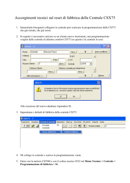
C421
14-10-2005
14:50
Pagina 3
Italian
Design
Since 1904
AF980
Tastiera per sistema filo
Keypad for hardwired systems
Manuale istruzioni
Instruction sheet
C421
14-10-2005
14:50
Pagina 6
Fig.1
Led di ZONA A
Led of ZONE A
Tasto esclusione ZONA A
ZONE A exclusion key
Tasto emergenza
Emergency key
Tasto esclusione ZONA B
ZONE B exclusion key
1
2
3
A
4
5
6
B
7
8
9
C
!
0
Tasto verde
Green key
Fig.2
Led di ZONA B
Led of ZONE B
Pulsante reset
Reset pushbutton
Tasto rosso
Red key
Tasto esclusione ZONA C
ZONE C exclusion key
12 11 10 7
8
9
1
5
6
2
3
4
Led di ZONA C
Led of ZONE C
L1
Fig.3
L1
J1
A
Vista frontale
Front view
B
Vista Interna
Internal view
–
쓒
2
+
쓒
E
Vista laterale
Side view
45378DF
1A - 30V
6
D
Vista inferiore
Lower view
Made in Italy
IN
4
5
3
C
Vista superiore
Top view
12V쓓
1
P1
J2
C421
14-10-2005
14:50
Pagina 1
Schema 1 - SCHEMA COLLEGAMENTO A CENTRALI ANTIFURTO AVE
Cod. AF53904, AF994, AF53907 E AF997.
(I numeri fra parentesi si riferiscono ai morsetti di collegamento alle centrali AF53907
e AF997).
Diagram 1 - WIRING DIAGRAM FOR AVE BURGLAR ALARM CONTROL
UNITS Codes AF53904, F994, AF53907 E AF997.
(The numbers in brackets refer to the AF53907 and AF997 control unit connection terminals).
1
2
3
A
4
5
6
B
7
8
9
C
!
0
1
19 (24)
2
21 (26)
3
20 (25)
8
10 (14)
–
+
24h
9
AF53904 - AF994
(AF53907 - AF997)
AF980
AF45342
2
3
AF45339
1
Schema 2 - SCHEMA COLLEGAMENTO PER COMANDO ELETTROSERRATURA O ATTIVAZIONE CENTRALE ANTIFURTO CON INGRESSO “STANDARD”.
Diagram 2 - WIRING DIAGRAM FOR ELECTROLOCK CONTROL OR BURGLAR ALARM CONTROL UNIT WITH STANDARD INPUT ENABLING
12Vca/cc
–
+
1
2
3
A
4
5
6
B
7
8
9
C
!
0
1
1
2
2
4
3
–
+
45378DF
AF980
AF45341
5
4
AF45339
3
ON
4
NA
5
C
6
NC
C421
14-10-2005
14:50
Pagina 1
I
AF980 Tastiera per sistema filo
INTRODUZIONE
La tastiera via filo AF980 (Fig.1) permette oltre all’inserimento disinserimento e parzializzazione di un impianto, l’attivazione, direttamente da tastiera, di un allarme “emergenza”.
Segnala inoltre lo stato dell’impianto ed un’eventuale anomalia del sistema.
Funziona anche in promiscuità con i punti di attivazione AF45342. È compatibile con il
sistema via filo Ave, quindi con le centrali AF53904, AF53907, AF994, AF997.
NOTA: la tastiera AF980 permette anche di comandare il decodificatore seriale
45378DF per comando elettroserratura o attivazione centrale antifurto con ingresso
”standard”.
CARATTERISTICHE TECNICHE
• Alimentazione: 12Vcc/ca ±10%
• Assorbimento max a 12Vcc:
- 4 mA in “inserito”
- 10 mA a riposo
• Protezione contro l’apertura e la rimozione con contatto NC
• Uscita allarme “emergenza” (contatto in scambio libero da potenziale) attivabile
direttamente da tastiera
• Codice utente a 4 cifre
• Possibilità di inserimento fino a 7 codici utente
• Segnalatore acustico incorporato per conferma manovre
• Distanza d’installazione massima dalla centrale: 200m
• Funzioni operative:
- inserimento impianto
- disinserimento impianto
- parzializzazione impianto
- allarme tamper
- allarme “emergenza”
• Fissaggio: a parete oppure ad incasso (formato maxi-modulo AVE)
• Materiale: ABS bianco RAL9016
• Grado di protezione: IP40
• Dimensioni: (125x102,5x30) mm
Conformità normativa
• EN 50081-1, EN50131-1, EN50130-4, EN61000-4 CEI 79-2, livello di prestazione
garantito: 1
-1-
C421
14-10-2005
14:50
Pagina 2
APPLICAZIONE ANTIFURTO AVE VIA FILO (schema 1)
PROGRAMMAZIONE
La programmazione della tastiera in centrale avviene in tre fasi diverse:
a) fase 1 in cui si procede all’attribuzione del codice master che permette l’accesso
alla programmazione dei codici sotto riportati;
b) fase 2 in cui si procede alla programmazione del vero e proprio codice di attivazione della centrale (codice tastiera);
c) fase 3 in cui si procede alla programmazione dei codici utente (ovvero i codici
utilizzabili dall’utente per le normali funzioni operative: inserimento, disinserimento,
parzializzazione).
Nota: la tastiera viene fornita “resettata”. Alla prima alimentazione è
quindi possibile immettere un codice master a piacere.
Successivamente il codice immesso verrà confrontato con quello già
memorizzato (vedi “protezione anti-scanner”).
PROGRAMMAZIONE
Nota: si consiglia di annotarsi il codice master ed aver cura di non perderlo. In caso contrario è necessario resettare la tastiera (vedi “reset
codici”).
FASE 1
Tenere premuti contemporaneamente i tasti rosso e
verde fino a sentire due “beep” di conferma.
Ad ogni pressione di un tasto si sentirà il beep
Inserire le 4 cifre del codice master (codice a piacere). di conferma, alla quarta cifra inserita i tre LED
della tastiera iniziano a lampeggiare insieme.
Premere contemporaneamente i tasti verde e rosso.
Codice master inserito.
I tre LED si accendono in sequenza continua
(giallo, rosso+verde, giallo, …) segnalando
la condizione di programmazione.
La tastiera resta per 30s nello stato di programmazione in attesa di altre istruzioni.
La tastiera esce in automatico dallo stato di
programmazione 30s dopo l’ultima pressione
di un qualsiasi tasto.
-2-
C421
14-10-2005
14:50
Pagina 3
FASE 2
Assicurarsi che la tastiera sia in programmazione
(led accesi in sequenza continua (giallo, ros- I tre LED sono accesi in sequenza continua
so+verde, giallo, …).
(giallo, rosso+verde, giallo, …) segnalando la
Se non lo fosse ripetere i passi della fase 1 inseren- condizione di programmazione.
do il codice master memorizzato in precedenza.
Tenere premuto il tasto rosso fino a sentire due
Verificare lo spegnimento dei tre led.
‘beep’ di conferma
Ogni numero va confermato con il tasto rosso
(beep di conferma).
Nota bene: se nell’impianto sono installati dei
Inserire fino ad un massimo di 12 numeri rappre- lettori AF45342, il codice tastiera da programsentanti i 12 bit del codice tastiera (equivalente dei mare deve coincidere con quello impostato
12 gommini della chiave AF45339, vedi fig.2).
sulla chiave AF45339 (i numeri da immettere
sono quelli non coperti dai gommini, nell’esempio di fig.2: 2, 4, 6, 8, 10), altrimenti inserire dodici cifre.
Confermato l’ultimo numero del codice tastiera, pre- Codice tastiera inserito. I tre led si accendono
mere il tasto rosso fino a sentire due ‘beep’ di con- in sequenza continua (giallo, rosso+verde,
giallo, …) segnalando la condizione di proferma.
grammazione.
La tastiera resta per 30s nello stato di programma- Questa programmazione deve essere ripetuta
zione in attesa di altre istruzioni.
per ciascuna tastiera dell’impianto.
La tastiera esce in automatico dallo stato di
programmazione 30s dopo l’ultima pressione
di un qualsiasi tasto.
FASE 3
Assicurarsi che la tastiera sia in programmazione
(led accesi in sequenza continua (giallo, I tre led sono accesi in sequenza continua
rosso+verde, giallo, …). Se non lo fosse ripetere i (giallo, rosso+verde, giallo, …) segnalando
passi della fase 1 inserendo il codice master la condizione di programmazione.
memorizzato in precedenza.
Tenere premuto il tasto verde fino a sentire
due ‘beep’ di conferma.
Verificare lo spegnimento dei tre led.
Inserire le 4 cifre del codice utente che si
vuole memorizzare.
Ad ogni pressione di un tasto si sentirà il
beep di conferma, alla quarta cifra inserita i
tre led della tastiera iniziano a lampeggiare.
Premere il tasto verde fino a sentire un
‘beep’ di conferma (seguito da altri due
beep consecutivi).
Se il codice è già presente in memoria tastiera si sentiranno 5 brevi beep.
La tastiera resta per 30s in attesa per
l’inserimento di altri codici utente.
Si possono inserire ulteriori codici (fino a 7)
ripetendo gli ultimi 3 passi. N.B. al tentativo
di inserire un ottavo codice si udiranno 5 brevi beep.
La tastiera esce in automatico dallo stato di programmazione.
N.B. questa programmazione deve essere ripetuta su ciascuna
tastiera dell’impianto; i codici utente potranno essere anche
diversi da tastiera a tastiera.
-3-
C421
14-10-2005
14:50
Pagina 4
Cancellazione del codice tastiera
È possibile cancellare il codice tastiera precedentemente memorizzato operando
come descritto di seguito:
Predisporre la tastiera in programmazione ripetendo
i passi della fase 1 ed inserendo il codice master
memorizzato in precedenza.
I tre LED sono accesi in sequenza continua (giallo, rosso+verde, giallo, …) segnalando la condizione di programmazione.
Tenere premuto il tasto rosso fino a sentire due
‘beep’ di conferma.
Verificare lo spegnimento dei tre LED.
Tenere premuti contemporaneamente i tasti rosso e
verde fino a sentire tre ‘beep’ brevi seguiti da un
‘beep’ lungo di conferma.
Comando cancellazione del codice tastiera.
Tenere premuto il tasto rosso fino a sentire due
‘beep’ di conferma.
I tre LED si accendono in sequenza continua
(giallo, rosso+verde, giallo,…) segnalando la
condizione di programmazione.
N.B. A questo punto è possibile memorizzare un
nuovo codice in centrale ed è sufficiente ripetere
la procedura descritta nella fase 2 disalimentando per qualche istante la centrale in modo da
cancellare anche in centrale il codice precedentemente memorizzato.
La tastiera esce in automatico dallo stato di programmazione 30s
dopo l’ultima pressione di un qualsiasi tasto.
La tastiera resta per 30s nello stato di programmazione in attesa di altre istruzioni.
Cancellazione di un codice utente
È possibile cancellare un codice utente precedentemente memorizzato operando
come descritto di seguito:
Predisporre la tastiera in programmazione ripetendo
i passi della fase 1 ed inserendo il codice master
memorizzato in precedenza.
I tre LED sono accesi in sequenza continua (giallo, rosso+verde, giallo, …) segnalando la condizione di programmazione.
Tenere premuto il tasto verde fino a sentire due
‘beep’ di conferma.
Verificare lo spegnimento dei tre LED.
Digitare le 4 cifre del codice utente che si
vuole cancellare
Ad ogni pressione di un tasto si sentirà un beep
di conferma. All’inserimento della quarta cifra i
tre LED della tastiera iniziano a lampeggiare.
Tenere premuti contemporaneamente i tasti
rosso e verde fino a sentire tre ‘beep’ brevi
seguiti da un ‘beep’ lungo di conferma della
cancellazione del codice.
Nel caso in cui il codice digitato non fosse presente nella memoria della tastiera si udiranno 5
brevi beep.
A questo punto i 3 LED si trovano spenti ed è possibile cancellare altri codici utenti inserendo le 4
cifre come al punto sopra.
Tenere premuto il tasto verde fino a sentire due
‘beep’ di conferma.
I tre LED si accendono in sequenza continua
(giallo, rosso+verde, giallo,…) segnalando la
condizione di programmazione.
N.B. A questo punto è possibile memorizzare
nuovi codici utenti con la sequenza vista in precedenza.
La tastiera esce in automatico dallo stato di programmazione 30s
dopo l’ultima pressione di un qualsiasi tasto.
La tastiera resta per 30s nello stato di
programmazione in attesa di altre istruzioni.
-4-
C421
14-10-2005
14:50
Pagina 5
Reset codici
Questa operazione consente di cancellare i codici master, tastiera ed utente
memorizzati.
1) Aprire il contenitore della tastiera.
2) Premere il pulsante interno di reset per 3s; si sentirà un “beep” e ci sarà lo spegnimento di ogni eventuale led acceso.
Inserimento, disinserimento, parzializzazione
Le operazioni di inserimento, disinserimento e parzializzazione possono essere effettuate come di seguito descritte, tramite la tastiera, dopo aver impostato il codice tastiera ed il codice utente, essere usciti dal livello programmazione e aver posto la chiave
della centrale in posizione ON.
INSERIMENTO
TOTALE
Digitare il codice utente a 4 cifre precedentemente memorizzato: inizieranno a lampeggiare i tre led presenti sulla
tastiera. Premere quindi il tasto rosso: si ha l’accensione
fissa di tutti i LED di zona (A, B, C); dopo un tempo di 1
minuto, sulla tastiera, rimane acceso il solo led verde, ad
indicare “impianto inserito”.
DISINSERIMENTO
Digitare il codice utente a 4 cifre precedentemente memorizzato: inizieranno a lampeggiare i tre led presenti sulla
tastiera. Premere quindi il tasto verde: i LED, in centrale, dei
canali che hanno memorizzato allarmi lampeggiano.
INSERIMENTO
PARZIALE
E’ possibile inserire le zone A – B – C singolarmente come
segue. Digitare il codice utente a 4 cifre precedentemente
memorizzato (inizieranno a lampeggiare i tre led presenti
sulla tastiera). Premere poi i tasti delle zone che si desiderano escludere (A, B, C). (I tre LED sulla tastiera relativi alle
zone confermano il comando impostato: LED acceso = zona
inserita). Controllare che l’impostazione sia quella desiderata e premere il tasto rosso.
I LED relativi alle zone inserite rimarranno accesi per 1
minuto trascorso il quale si accende o rimane acceso il solo
led verde, ad indicare “impianto inserito” senza rilevare l’eventuale parzializzazione.
Lo stato di parzializzazione impostato rimane memorizzato
fino al prossimo disinserimento dell’impianto.
Protezione “anti-scanner”
Se il codice utente o il codice master non corrispondono a quelli memorizzati, dopo il
terzo tentativo, la tastiera si pone in stand-by per 30s, segnalando questo stato con il
lampeggio del led giallo: durante tale periodo non è possibile immettere altri codici.
Segnalazioni ausiliarie
La tastiera fornisce inoltre importanti informazioni sullo stato dell’impianto con le
segnalazioni di “anomalia” e “allarme”. Tali segnalazioni sono riassuntive ed hanno lo
scopo di richiamare l’utente al controllo delle spie della centrale per verificare in dettaglio gli eventi accaduti. La tabella di seguito riportata indica come queste informazioni
-5-
C421
14-10-2005
14:50
Pagina 6
vengono segnalate ed il relativo significato.
Led di ZONA A verde: lampeggiante. Riassume uno o più dei
seguenti punti:
• batteria scarica (la centrale non può essere inserita; è possibile la disinserzione)
ANOMALIA • una o più linee aperte (indicazione visualizzata solo con centrale
disinserita)
• una o più linee escluse mediante appositi pulsanti di esclusione
zone posti in centrale (indicazione visualizzata solo con centrale
disinserita)
ALLARME
Led di ZONA C rosso: lampeggiante. Indica che una o più delle
zone dell’impianto inserite è stata effratta e/o manomessa (indicazione presente solo ad impianto inserito).
Tasto emergenza
Sulla tastiera è presente un tasto per chiamata di emergenza ! . Se premuto per
almeno 2s, un relè interno commuta per 3 min. Tale contatto può essere gestito sia
dalla centrale antifurto che da un combinatore telefonico, per trasferire l’allarme.
DESCRIZIONE MORSETTIERA
Morsetti Descrizione
1
Negativo alimentazione
2
Positivo alimentazione
3
Segnale linea seriale per centrali antifurto AVE
4
Segnale linea seriale per decodificatore 45378DF
5
Contatto NA allarme emergenza
6
Contatto C allarme emergenza
7
Contatto NC allarme emergenza
8
Tamper
9
Tamper
APPLICAZIONE PER COMANDO ELETTROSERRATURA O ATTIVAZIONE CENTRALE ANTIFURTOCON INGRESSO ”STANDARD” (schema 2)
Con questa applicazione è possibile utilizzare la tastiera per attivare/disattivare sistemi
antifurto non Ave o comandare un elettroserratura, convertendo l’uscita seriale della
tastiera in un contatto libero da potenziale del decodificatore cod. 45378DF programmabile.
Memorizzazione codice master
Non ci sono differenze rispetto alla fase 1 precedentemente descritta.
Programmazione del codice tastiera e memorizzazione nel decodificatore
1) Inserire il ponticello di programmazione J2 nel decodificatore 45378DF (fig.3C).
2) Procedere come ai punti 2), 3) e 4) della fase 2 precedentemente descritta.
-6-
C421
14-10-2005
14:50
Pagina 7
Nota: se nell’impianto esistono dei lettori AF45341 (vedi Schema 2) e si
volesse far coincidere il codice tastiera con quello impostato su una
chiave AF45339, i numeri da immettere sarebbero quelli non coperti dai
gommini; (nell’esempio di Fig. 2: 2, 4, 6, 8, 10).
3) Terminata la programmazione premere il tasto rosso per 5s, fino a sentire due
“beep”; i led torneranno ad accendersi in sequenza (giallo, verde+rosso, giallo,
ecc.). Se il codice è correttamente memorizzato il led L1 del decodificatore lampeggerà lentamente per circa 2 secondi. A questo punto il codice tastiera è memorizzato nel decodificatore ed è quindi possibile memorizzare un nuovo codice o uscire
dalla modalità programmazione estraendo il ponticello J2.
3a) Se il led L1 del decodificatore lampeggia velocemente per 20 secondi, significa
che il decodificatore ha rilevato un errore: o la memoria è esaurita (possono essere memorizzati fino ad un massimo di 8 codici), o il codice giunto al decodificatore non è corretto: in quest'ultimo caso è necessario ripetere la programmazione;
4) Estrarre il ponticello di programmazione J2 dal decodificatore 45378DF.
Programmazione dei codici utente
Non ci sono differenze rispetto alla fase 3 precedentemente descritta.
Cancellazione del codice tastiera
Non ci sono differenze rispetto a “cancellazione del codice tastiera” sopra
descritto, se non al punto 4):
4) premere il tasto rosso per 5s, fino a sentire due “beep”; i led torneranno ad accendersi in sequenza (giallo, verde+rosso, giallo, ecc.). A questo punto il codice tastiera è cancellato. Per memorizzare un nuovo codice sul 45378DF è sufficiente ripetere la procedura precedentemente descritta in “programmazione del codice tastiera”.
Il nuovo codice verrà memorizzato assieme al precedente, sempre che ci sia almeno
una delle otto celle di memoria libere. In caso contrario bisogna prima resettare il
decodificatore.
Cancellazione di un codice utente
Non ci sono differenze rispetto a “cancellazione di un codice utente” precedentemente descritta.
Attivazione/disattivazione del decodificatore seriale 45378DF
Assicurarsi che il ponticello di programmazione J2 nel decodificatore sia disinserito.
Digitare un codice utente: inizieranno a lampeggiare i tre Led presenti sulla tastiera.
Premere quindi il tasto rosso per inviare il codice al decodificatore:
• se il codice giunto al decodificatore corrisponde ad uno memorizzato, verrà attivata
l'uscita con tipologia di funzionamento scelta attraverso il ponticello J1. A detto
ponticello (J1), situato immediatamente sotto il led L1 (fig. 3B), si accede dopo aver
rimosso la mostrina del decodificatore. Sono possibili due diverse tipologie di funzionamento:
a) J1 inserito: funzionamento monostabile. In questo stato, all'arrivo di un codice
riconosciuto, il decodificatore attiva l'uscita per due secondi e quindi la disattiva.
Durante l'attivazione dell'uscita il dispositivo ignora tutti gli eventuali codici in
arrivo.
b) J1 disinserito: funzionamento bistabile. In questo stato, all'arrivo di un codice
riconosciuto, il decodificatore cambia lo stato dell'uscita: avviene una commuta-7-
C421
14-10-2005
14:50
Pagina 8
zione del contatto (NA+NC) del relè d’uscita.
• se il codice è errato, il led L1 lampeggerà velocemente per circa 20 secondi: durante
questo tempo il decodificatore non accetta alcun codice.
NOTA: se il decodificatore viene installato in sistemi che richiedono una
elevata sicurezza (es. impianti antintrusione, ecc.) è necessario collegare l'alimentazione del dispositivo ad un sistema di alimentazione in tampone, in modo che eventuali mancanze della tensione di rete protratte
nel tempo, non possano causare un decadimento delle prestazioni del
decodificatore.
Cancellazione codici memorizzati nel decodificatore
E’ possibile cancellare tutti i codici precedentemente memorizzati esercitando una
pressione continua per 3 secondi sul pulsante di reset P1 (fig. 3D). La pressione del
pulsante P1 causa inoltre il diseccitamento del relè d’uscita.
DESCRIZIONE MORSETTIERA DECODIFICATORE
Morsetti/
Ponticello
1
2
3
4
5
6
J1
J2
P1
Descrizione
Negativo alimentazione
Positivo alimentazione
Ingresso seriale
Contatto NA
Contatto comune
Contatto NC
Permette di selezionare la tipologia di funzionamento dell’uscita
(monostabile o bistabile)
Permette il passaggio da modalità programmazione
a modalità operativa
Permette di cancellare i codici memorizzati
CARATTERISTICHE TECNICHE DECODIFICATORE 45378DF
• Tensione nominale: 12Vcc/ca
• Variazione ammessa: da 10 a 15Vcc oppure a 12Vac (-20%, +30%max)
• Assorbimento massimo: 25mA con relé eccitato, led acceso e trasmissione codice
in corso
• Ingressi: 2 morsetti per ingresso seriale da lettore chiave (AF45341)
• Uscite: 3 morsetti per contatto in scambio 1A/30V NA+NC liberi da potenziale
• Segnalazioni di stato tramite LED
• Numero massimo di codici memorizzabili: 8
• Pulsante P1: per cancellazione di tutti i codici appresi
• Ponticello J1: per selezionare la tipologia di funzionamento (monostabile o bistabile)
• Ponticello J2: per accedere alla modalità programmazione
• Installazione: da interno, ad incasso o a parete nello specifico contenitore
• Dimensioni: 1 modulo sistema 45.
-8-
C421
14-10-2005
14:50
Pagina 4
AVVERTENZE I prodotti devono essere commercializzati in confezione originale, in caso
contrario al rivenditore e/o installatore è fatto obbligo di applicare e di trasmettere all'utilizzatore le istruzioni d'uso che accompagnano il prodotto. Dopo aver aperto l'imballaggio,
assicurarsi dell'integrità dell'apparecchio, nel dubbio non utilizzare l'apparecchio e rivolgersi a personale professionalmente qualificato. L'apparecchio, anche se imballato, deve essere maneggiato con cura e immagazzinato in luogo asciutto ad una temperatura compresa tra
–5…+40°C.
Si ricorda inoltre:
• La garanzia di 5 anni si applica per difetti e non conformità di prodotto imputabili al costruttore fermi restando i
diritti e gli obblighi derivanti dalle disposizioni legislative vigenti (artt. 1490, 1512 C.C., DL 24/2002, Direttiva
1999/44/CE, art. 1519 C.C.). Il difetto deve essere denunciato entro due mesi dalla data della scoperta dello stesso. I cinque anni si intendono dal momento della consegna del prodotto da parte di AVE.
• L’installazione deve essere effettuata da personale qualificato.
• Togliere tensione agendo sull'interruttore generale prima di operare sull'impianto.
• Curare in modo particolare la preparazione dei terminali dei cavi da inserire nei morsetti dell'apparecchio per evitare la riduzione delle distanze di isolamento tra gli stessi. Utilizzare conduttori con sezione max 1,5 mm2.
• Serrare le viti dei morsetti con cura per evitare surriscaldamenti che potrebbero provocare un incendio o il danneggiamento dei cavi.
• Il prodotto, è destinato all'utilizzo in luoghi asciutti e non polverosi.
Per ambienti particolari utilizzare prodotti specifici.
• È possibile il pericolo di scossa elettrica o di malfunzionamento se l’apparecchio viene manomesso.
• Installare prodotti e accessori secondo le prescrizioni della norma vigente per gli impianti elettrici.
C421
14-10-2005
14:50
Pagina 9
GB
AF980 Keypad for hardwired systems
INTRODUCTION
Hardwired keypad AF980 (Fig.1) allows not only connection, disconnection and partial
setting of an anti-intrusion system but it also allows to send an “emergency” alarm
directly from the keypad.
It reports the system status and any failures of the system. It can be combined with
activation points AF45342. It is compatible with the Ave hardwired systems, that is
with control units AF53904, AF53907, AF994, AF997.
NOTE: keypad AF980 can also control serial decoder 45378DF to control electrolocks
or to enable burglar-alarm control units with standard input.
TECHNICAL DATA
• Power supply: 12 Vdc/ac ± 10%
• Max. current consumption at 12Vdc:
- 4 mA in ON mode
- 10 mA in stand-by
• Tamper protection against opening and removal through a NC contact
• Emergency alarm output (changeover potential-free contact) to be enabled directly
from the keypad
• 4-figure user code
• Possibility of inserting up to 7 user codes
• Built-in buzzer to confirm operations
• Max. installation distance from the alarm control unit: 200 m
• Operating functions:
- system connection
- system disconnection
- system partial setting
- tamper alarm
- emergency alarm
• Installation: wall or flush-mounting (AVE maxi-module)
• Material: RAL9016 white ABS
• Protection degree: IP40
• Dimensions: (125x102,5x30) mm
Standard compliance
• EN 50081-1, EN50131-1, EN50130-4, EN61000-4
CEI 79-2, performance level assured: 1
-9-
C421
14-10-2005
14:50
Pagina 10
AVE HARDWIRED BURGLAR ALARM
CONTROL UNIT APPLICATION (diagram 1)
PROGRAMMING
The programming of the keypad in a burglar alarm control unit is made up of the following three phases:
a) phase 1: the master code allowing to enter programming of the codes listed
below is assigned;
b) phase 2 programming of the control unit proper activation code is carried out
(keypad code);
c) phase 3 programming of the user codes is carried out (that is the codes to be
used by the user for the standard operating functions: connection, disconnection,
partial setting).
Note: When the keypad is supplied to the customer, it is reset. Upon
powering it for the first time, master code you want can be inserted.
Then, the inserted code will be compared with the previously stored one
(see “anti-scanner protection”).
PROGRAMMING
Note: it is recommended to write down the master code and not to loose
it. Otherwise, the keypad must be reset (see “code reset”).
PHASE 1
Keep the red and green keys pressed simultaneously
until when a confirmation “beep” is heard.
Every time a key is pressed, a confirmation
beep will be heard. As soon as 4 figures are
Insert the 4 figures of the master code (a code as you inserted, the three LEDs of the keypad will
like).
start flashing at the same time
The master code has been inserted.
The three LEDS switch on in sequence (yellow, red+green, yellow, …) to signal the programming mode in progress.
Press the green and red key at the same time.
The keypad remains in programming mode for 30
seconds awaiting further instructions.
The keypad exits from the programming mode
automatically, after 30 seconds from the last
pressure of any key.
- 10 -
C421
14-10-2005
14:50
Pagina 11
Make sure that the keypad is in programming mode
(leds on in a continuous sequence (yellow, The three LEDS are ON in sequence (yellow,
red+green, yellow, …). If this is not the case, repeat red+green, yellow, …) to signal the programthe different steps of phase 1 and insert the master ming mode in progress.
code previously stored.
PHASE 2
Keep the red key pressed until when two confirmation beeps are heard.
Make sure that the three leds switch off.
Every number must be confirmed with the red
key (confirmation beep).
Note: if the system is provided with AF45342
Insert up to 12 numbers max. representing the 12 readers, the keypad code to be programmed
bits of the keypad code (corresponding to the 12 must correspond to the one set on key
rubber pads of key AF45339, see fig.2).
AF45339 (the numbers to be inserted are the
ones not covered by rubber pads. In the example of figure 2: 2, 4, 6, 8, 10), otherwise insert
twelve figures
After confirming the last number of the keypad code, The keypad code has been inserted.
press the red key until two confirmation beeps are The three LEDS switch on in sequence (yellow,
heard.
red+green, yellow, …) to signal the programming mode in progress.
The keypad remains in programming mode for 30 This programming must be repeated for each
seconds awaiting further instructions.
keypad of the system.
The keypad exits from the programming mode
automatically, after 30 seconds from the last
pressure of any key.
Make sure that the keypad is in programming mode
leds ON in a continuous sequence (yellow, The three LEDS are ON in sequence (yellow,
red+green, yellow, …). If this is not the case, repeat red+green, yellow, …) to signal the programthe different steps of phase 1 and insert the master ming mode in progress.
code previously stored.
PHASE 3
Keep the green key pressed until when two
confirmation beeps are heard
Make sure that the three leds switch off.
Insert the 4 figures of the user code to be
stored.
Every time a key is pressed, a confirmation
beep will be heard. As soon as 4 figures are
inserted, the three LEDs of the keypad will
start flashing.
Press the green key until when a
confirmation beep is heard (followed by
another two consecutive beeps)
If the code has already been stored, 5 short
beeps will be heard.
The keypad remains in stand-by for 30
seconds waiting for further user codes to
be inserted.
Further codes can be inserted (up to 7) by
repeating the last three steps.
Note: upon trying to insert the eighth code, 5
short beeps will be heard.
The keypad exits from the programming mode automatically.
Note. This programming must be repeated on each keypad of the
system; the user codes may differ on each keypad.
- 11 -
C421
14-10-2005
14:50
Pagina 12
Keypad code deletion
The keypad code previously stored can be deleted according to the instructions
listed below:
Set the keypad to programming mode by repeating
the steps of phase 1 and inserting the master code
previously stored.
The three LEDS are ON in a continuous sequence
(yellow, red+green, yellow, …) to signal the programming mode in progress.
Keep the red key pressed until when two
confirmation beeps are heard.
Make sure that the three leds switch off.
Keep the red and green keys pressed at the same
time until when three short beeps followed by a long
confirmation beep are heard.
Deletion control of the keypad code.
Keep the red key pressed until when two
confirmation beeps are heard.
The three LEDS switch on in sequence (yellow,
red+green, yellow, …) to signal the programming mode in progress.
Note: Now a new code can be stored in the control unit by repeating the procedure described in
phase 2 by disconnecting the control unit for a
few seconds in order to delete the previously stored code also from the control unit itself.
The keypad remains in programming mode for 30
seconds awaiting further instructions.
The keypad exits from the programming mode automatically,
after 30 seconds from the last pressure of any key.
User code deletion
The user code previously stored can be deleted according to the instructions listed
below:
Set the keypad to programming mode by repeating
the steps of phase 1 and inserting the master code
previously stored.
The three LEDS are ON in a continuous sequence
(yellow, red+green, yellow, …) to signal the programming mode in progress.
Keep the green key pressed until when two
confirmation beeps are heard.
Make sure that the three leds switch off.
Insert the 4 figures of the user code to be
deleted.
Every time a key is pressed, a confirmation beep
will be heard. Upon inserting the fourth figure, the
three LEDs of the keypad will start flashing.
Keep the red and green keys pressed at the
same time until when three short beeps
followed by a long beep confirming that the
code has been deleted, are heard.
If the code inserted is not already included in the
keypad storage, 5 short beeps will be heard.
Now, the three LEDs are OFF and further user
codes can be deleted by inserting the four figures
as per the step mentioned above.
Keep the green key pressed until when two
confirmation beeps are heard.
The three LEDS switch ON in sequence (yellow,
red+green, yellow, …) to signal the programming
mode in progress.
The keypad remains in programming mode for 30
seconds awaiting further instructions.
Note: Now new user codes can be stored according to the previously described procedure.
The keypad exits from the programming mode automatically, after
30 seconds from the last pressure of any key.
- 12 -
C421
14-10-2005
14:50
Pagina 13
Code reset
This procedure allows to delete the master, keypad and user codes previously
stored.
1) Open the keypad enclosure.
2) Press the internal reset pushbutton for 3s; a beep is heard and any led ON will
switch OFF.
Connection, Disconnection, partial setting
Connection, disconnection and partial setting can be carried out according to the
instructions below, through the keypad, after setting the keypad code and the user
code, exiting from the programming mode and setting the control unit key to ON position.
FULL
CONNECTION
Insert the 4-figure user code previously stored: the three
leds seated on the keypad will start flashing. Press the red
key: all the zone LEDs (A, B, C) will switch ON; after 1 minute, only the green led signalling the “system connected” status will remain ON.
DISCONNECTION
Insert the 4-figure user code previously stored: the three
leds seated on the keypad will start flashing. Press the green
led: in the control unit, the LEDs of the channels that have
stored alarms, will start flashing.
PARTIAL
SETTING
Zones A – B – C can be enabled individually as follows.
Insert the 4-figure user code previously stored (the three
leds seated on the keypad will start flashing).
Then, press the keys of the zones to be excluded (A, B, C).
(the three leds seated on the keypad related to the zones will
confirm the set command: LED ON = zone enabled). Make
sure that setting is the desired one and press the red key.
The LEDs related to the zones enabled will remain ON for 1
minute. Once this time is over, only the green led will switch
ON or remain ON to signal the “connected system” status
without detecting the partial setting, if any.
The preset partial setting remains stored up to the next disconnection of the system.
“Anti-scanner” protection
If the user code or the master code do not correspond to the stored ones, after the third
attempt, the keypad will set to stand-by for 30s; the yellow led will flash to signal this
status; during this time no further codes can be inserted.
Auxiliary signals
The keypad supplies important information on the status of the system such as anomaly and alarm warning signals. These warning signals are recapitulatory and make
the user control the pilot lamps of the control unit to check the events occurred in
detail. The table below shows the way this information is signalled along with its meaning.
- 13 -
C421
14-10-2005
14:50
Pagina 14
ANOMALY
ZONE A green led: flashing.
It summarizes one or several following situations:
• flat battery (the control unit cannot be connected; disconnection is
possible)
• one or several lines are open (this signal is displayed only if the
control unit is disconnected)
• one or several lines are excluded by means of special zone exclusion pushbuttons seated on the control unit (this signal is displayed only if the control unit is disconnected)
ALARM
ZONE C red led: flashing. It indicates that one or several system
zones enabled have been tampered and/or forced (this signal is displayed only if the control unit is connected)
Emergency key
The keypad is provided with an emergency call key. !
If it is pressed for 2 seconds at least, an internal relay will change over for 3 minutes.
This contact can be managed both by the burglar alarm control unit and by a telephone
dialler to transfer the alarm.
TERMINALBOARD DESCRIPTION
Terminal n.
1
2
3
4
5
6
7
8
9
Description
Power supply negative
Power supply positive
Serial line signal for AVE burglar alarm control units
Serial line signal for 45378DF decoder
Emergency alarm NO contact
Emergency alarm C contact
Emergency alarm NC contact
Tamper
Tamper
APPLICATION FOR ELECTROLOCK CONTROL OR CONNECTION OF BURGLAR ALARM CONTROL UNIT WITH STANDARD
INPUT (diagram 2)
Thanks to this application, the keypad can be used to enable/disable burglar alarm
systems not manufactured by AVE or to control an electrolock by transforming the keypad serial output into a potential-free contact of the programmable decoder code
45378DF.
Storing the master code
There are no differences compared to the previously described phase 1.
Keypad code programming and decoder storing
1) Insert programming jumper J2 into the decoder code 45378DF (fig.3C).
2) Proceed as per items 2), 3) and 4) of the previously described phase 2.
- 14 -
C421
14-10-2005
14:50
Pagina 15
Note: if the system is provided with readers AF45341 (see diagram 2) and
you want the keypad code correspond to the one set on a AF45339 key,
the numbers to be inserted are the ones not covered with rubber pads; (in
the example of fig. 2: 2, 4, 6, 8, 10).
3) Once programming is over, press the red key for 5s until when two beeps are heard;
the leds will switch on again in sequence (yellow, green+red, yellow, ecc.). if the
code has been stored correctly, led L1 of the decoder will flash slowly for 2 seconds
approx. Now the keypad code is stored in the decoder and a new code can be stored, otherwise exit from the programming mode by removing jumper J2.
3a) If the decoder led flashes quickly for 20 seconds, it means that the decoder has
detected an error: memory is full (up to a maximum of 8 codes can be stored), or
the code sent to the decoder is wrong: in this last case, programming must be
repeated;
4) Remove programming jumper J2 from the 45378DF decoder.
User code programming
There are no differences compared to the previously described phase 3.
Keypad code deletion
There are no differences compared to the previously described section “keypad
code deletion” except for item 4):
4) press the red key for 5s until when two beeps are heard; the leds will switch on again
in sequence (yellow, green+red, yellow, etc.). Now the keypad code is deleted. To
store a new code on decoder 45378DF just repeat the procedure described in “keypad code programming”. The new code will be stored along with the previous one,
provided that one of the eight memory cells at least, is free. Otherwise, first reset the
decoder.
Deletion of a user code
There are no differences compared to the previously described section “deletion of a
user code.
Enabling/disabling of serial decoder 45378DF
Make sure that programming jumper J2 of the decoder is not inserted.
Insert a user code: the three leds seated on the keypad will start flashing.
Then, press the red key to send the code to the decoder:
• if the code received by the decoder corresponds to a stored one, the output with the
operation desired will be enabled by means of jumper J1. To reach this jumper (J1),
which is seated immediately under led L1 (fig. 3B), remove the decoder blank plate.
Two operating modes are available:
a) J1 inserted: monostable operation. In this mode, as soon as a recognized code
arrives, the decoder enables the output for two seconds and then it disables it.
Upon enabling the output, the device ignores all incoming codes, if any.
b) J1 not inserted: bistable operation. In this mode, as soon as a recognized code
arrives, the decoder changes the output status: the output relay contact (NO+NC)
is changed over.
• if the code is wrong, led L1 will flash quickly for 20 seconds approx.: during this
time the decoder does not accept any code.
NOTE: if the decoder is installed on systems requiring a high level of
- 15 -
C421
14-10-2005
14:50
Pagina 16
security (for ex. Intrusion alarm systems, etc.) the power supply of the
device must be connected to a buffer power supply system so that, in the
event of long mains failure, the decoder performance is not jeopardized.
Deletion of codes stored in the decoder
All previously stored codes can be deleted by pressing the reset pushbutton P1 for 3
seconds (fig. 3D). Moreover, by pressing pushbutton P1, the output relay will be deenergized.
DECODER TERMINAL BOARD DESCRIPTION
Terminals
Jumper
1
2
3
4
5
6
J1
J2
P1
Description
Power supply negative
Power supply positive
Serial input
NO contact
Common contact
NC contact
To select the operating mode of the output (monostable or bistable)
To move from the programming mode to the operating mode
To delete the stored codes
TECHNICAL DATA OF DECODER 45378DF
• Rated voltage: 12Vdc/ac
• Permitted change: 10 to 15Vdc or at 12Vac (-20%, +30%max)
• Max. consumption: 25mA with excited relay, led ON and code transmission in progress
• Inputs: 2 terminals each key reader serial input (AF45341)
• Outputs: 3 terminals each changeover potential-free contact 1A/30V NO+NC
• Status signalling LEDs
• Maximum number of storable codes: 8
• P1 pushbutton: to delete all codes acknowledged
• J1 jumper: to select the operating mode (monostable or bistable)
• J2 jumper: to enter the programming mode
• Installation: indoor, wall or flush-mounting in the special enclosure
• Dimensions: 1 S45 module.
- 16 -
C421
14-10-2005
14:50
Pagina 5
NOTE Products should be sold in their original packaging. When this is not the case, the
retailer or/and the installer is obliged to follow, as well as communicate to the user, the
instructions for use which are supplied with the product. After opening the packaging, check
that the appliance is undamaged. Do not use the appliance if there is any doubt, but contact
a qualified technician. Even before unpacking, the appliance should be handled with care
and stored in a dry place at temperatures between –5°C and +40°C.
Also note:
• The 5 years warranty is applicable for any defect in or failing of the goods caused by the manufacturer’s negligence. It doesn’t affect your statutory rights as prescribed by law (art. 1490, 1512 C.C., DL 24/2002, Directive
1999/44/CE, art. 1519 C.C.). The defect must be notified within 2 month from the date it was discovered. Five
years are intended from the date of delivery of the goods by AVE.
• Installation must be carried out by qualified technicians.
• Before carrying out any maintenance on the appliance, cut off the mains power.
• Special care should be taken in the preparation of the cable terminals to be inserted into the appliance terminals
so as to maintain sufficient isolation distance between them. Use 1.5 mm2 section wires.
• When tightening the terminal screws, special care should be taken to avoid overheating which could start a fire or
damage the cables.
• The product must be used in dry, dust-free areas. Suitable products must be used in any other conditions.
• There is the possibility of electric shocks or failure of the device if the device is tampered with.
• Install products and accessories according to the standards in force for electrical systems.
14-10-2005
14:50
Pagina 2
C.421-02-101005
C421
Italian
Design
Since 1904
www.ave.it
[email protected]
Scaricare