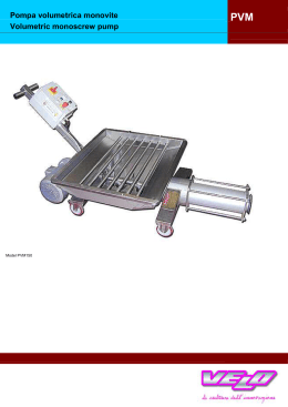
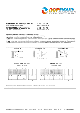
Monoblock centrifugal pumps Elettropompe centrifughe monoblocco CS ME CS Operating instructions Libretto istruzione RUS Инструкция по зксплуaтaции ME INSTRUCTIONS FOR THE INSTALLATION AND USE OF ELECTROPUMPS Warning: 1. General This manual is meant to provide the user with the essential information required for installing, using and servicing the pumps. A fault-finding chart indicating possible cause and remedy for every problem which might occur, is included. For operation in hot damp environments, the pump should not be installed orientated to different directions than normal, to avoid condensation water building up inside the motor. Avoid vertical position with motor facing down ward (see installation diagram - Fig. 5). Being generously dimensioned, these pumps can be supported by the pipework of the system to which they are applied, even though it would be preferable - where possible - to secure them firmly to a bedplated by means of four holding-down bolts fitted through the holes provided in the pump feet. Firm mounting will aid to damp down vibrations, if any. A satisfactory installation should conform to the following indications: The suction pipe, the inside diameter of which should never be smaller than the pump inlet, should be dimensioned consistently with the system and the pumped liquid. Bear in mind that the maximum theoretical suction lift not only is reduced by the NPSHr required by the pump, which is a peculier characteristic of the pump itself, but is also reduced by the height above sea level of the installation and the friction losses occurring in the suction line. Therefore, in order to avoid cavitation, which would generate noise, performance drop and vibrations that might exert undue mechanicals stress on the pump, the following relation should always be observed: 2. Technical characteristics and materials The electric pumps are the centrifugal, radial, closecoupled type, with single impeller. • Cast iron pump-body and support, stainless steel threaded counter flanges. • Stainless steel motor shaft; bronze impeller for the high head range; cast iron impeller for the low head range. • Mechanical seal housing standardized to DIN 24960. The mechanical seal is lubricated by the pumped liquid. • All the electric pumps come fitted with threaded counter-flanges. • Amply dimensioned ball-bearings pre-packed with special grease for life. • 2 pole electric motors of enclosed type, IP 55, with external ventilation; insulated according to Class F. • Standard supply voltages: 50 Hz=230/400 V up to 7,5 kW - 400/700 V for higher power ratings. 60 Hz=230/400 V for all powers. Standard voltage V 230 - 50 Hz. On request, special voltages available. • In the standard versions the electric pumps are suitable for fluid temperatures up to 60°C. • Maximum working pressure: 10 Bar. hp + hz ≥ (NPSHr + 0.5) + hf + hpv where: hp is the absolute pressure acting on the free surface of the liquid in the suction reservoir, expressed in meters of liquid. hp is the quotient between the barometric pressure and the specific weight of the liquid. 3. Applications The electric pumps are suitable for application in the civil, agricultural and industrial fields, to pump chemically or mechanically non aggressive liquids. Any suspended solid particles should not exceed 2% by weight. The following are but a few typical applications: water supply systems, irrigation schemes, pressure tank feed, pressure boosting, air conditioning system, heating systems. hz is the difference in level between the pump axis and the free surface of the liquid in the suction reservoir expressed in metres. hz is negative when the liquid level is below the pump axis. 4. Installation hf The pumps may also be located outdoor, provided they are suitable protected by a roofing; they can also be installed inclined or vertically. is the head loss occurring within the suction line and the fittings fitted to it, such as connectors, foot valve, sluice valves, bens, etc. 2 The head losses can be read from the diagram shown in our catalogue, and in order to reduce them to a minimum - mainly where suction is remarkable (over 4-5 metres) or when operating at the highest flow rates - it is advisable to use a section pipe larger than the pump inlet. In all cases it is advisable that the pump be installed as close as possible to the source of the pumped liquid. hpv is the vapour pressure of the liquid at the operating temperature, expressed in metres of liquid. hpv is the quotient between the vapour pressure and the specific weight of the liquid. 0.5 is a margin of safety. From the above relation it can be gathered that the maximum permissible suction lift in an installation depends on the value of the atmospheric pressure (i.e. the height above sea level of the installation) and the liquid temperature. To facilitate the user’s task, tables are provided which - the datum being water at 4°C and at sea level - indicate the decrease in the hydraulic pressure head as a function of the height above sea level and the suction losses as a function of the temperature. fig. 1 - Pump installation A Right Water temperature (°C) Suction loss (m) 20 0,2 40 0,7 60 2,0 80 5,0 90 7,4 110 15,4 120 21,5 Height above sea level (m) Suction losses in m. 500 0,55 1000 1,1 1500 1,65 2000 2,2 2500 2,75 3000 3,3 • • • • • • Eccentric reducer Positive inclination Good immersion Ample bends Suction pipe dia.≥ pump inlet Check valve at the delivery B Wrong • Reducer and negative inclination generate air locks • Scanty immersion=vortex and whirlpools • Sharp bends • Narrow piping 3 INSTRUCTIONS FOR THE INSTALLATION AND USE OF ELECTROPUMPS The suction line should be slightly inclined up towards the pumps and any reducers should be eccentric (see fig. 1) to prevent air locks. In any such installations where the operating conditions require that the pump delivery be restricted or modulated, we recommend that a relief valve be fitted to the delivery pipe, or a re-cycle by-pass put between the delivery and the supply reservoir. We recommend that a non-return valve be fitted to the delivery pipe close to the pump to protect it from any dynamic stresses caused by water hammer, and a foot valve be put at the end of the suction pipe to facilitate priming. 4.2 Checking the direction of rotation of the electric pumps with three phase motors 4.1 Wiring up motor Priming is accomplished by filling the pump and the suction line with the liquid to be pumped. To fill the pump, remove the filling plug and proceed as follows: – Pump with positive suction head: open the sluice valve at the suction and let the liquid flow in until it brims over the filling plug. N.B. The function of the sluice valve at the suction is to intercept the liquid flow and not to control the flow rate as this is only accomplished by a sluice valve fitted to the dellivery. – Pump with negative suction head, fitted with foot valve: fill the pump and the suction line through the filling plugs. This operation may be shortened by filling the pump through the pump outlet. During the filling stage take care to let all air escape please note that filling is completed correctly only after the water level at the filling plus is stable and all air bubbles have disappeared. – Pump with negative suction head, without foot valve. In this case filling is a bit more complicated as a pressurized liquid or air source would be required, along with an ejector or a vacuum pump. In such instance, a perfectly watertight sluice valve must be fitted to the delivery. As fitting is completed, start the pump and check that both pressure and flow rate are constant; if that is not the case, stop the pump and repeat the entire operation. The direction of rotation may be checked before the pump is fitted with the liquid to be pumped, provided it is run for very brief intervals only. The pump must not be run before it is filled with liquid. Continuous dry running would damage the mechanical seal beyond repair. If the direction of rotation is not anti-clockwise, as viewing the pumps from the pump inlet, then interchange two supply leads. 4.3 Priming Make sure that the specifications written on the motor plate are correct for the electrical supply line. Remove the terminal box cover, inside which is illustrated the wiring diagram. Caution: the unit must be grounded before you make any other connections. Single phase motors Wire up the motor as illustrated inside the terminal box cover. The connections are pre-arranged for the correct direction of rotation - which is anti-clockwise when the pump is viewed from the pump inlet. Three phase motors The thermal overload protection is to be provided by the user, with motor protector complete with remote control switch, thermal relay and fuses installed upstream. The overload relay must be set to the full rated load value (In) written on the motor plate. The thermal relay may be set to a current value slightly lower than the full load value when electric pump is definetely underloaded, but the thermal overload protection must not be set to current values higher than the full load values. Any operation at current values slightly higher than the full load values (max. 1.1 In) may be tolerated, provided they are only due to occasional sudden changes in the supply voltage. We also recommend that an omnipolar switch be installed upstream of the motor protector in order to fully insulate the electric pump from the electric supply line. Where two pumps are installed (one being a stand-by unit) a commutator should be provided between the two pumps in order to equalize the wear rate of both pumps. 5. Running If all the above operations-installation, filling, etc,. are carried out correctly, the pump will offer quiet running. – With liquid temperatures higher than the test temperature, the manometric delivery head will decrease in relation to the specific weight of the liquid. – When handling viscous liquids, both flow rate and head would decrease, while the power input would increase. 4 In such instance the maximum rated flow rate should be reduced, to avoid the overload protection tripping too often. – The pump should not be subjected to more than 20 startings per hour, to avoid excessive thermal stress on the motor. Where a star-delta starter is used, the above number of startings per hour may the slightly increased. – The pump should not run for long periods with closed sluice valve at the delivery. Where this is inevitable, or in all such instances where the delivery rate is to be modulated, proceed as directed under the section “installation”. – All pumps which are installed in places unprotected from frost must be emptied whenever they remain inoperative, and flushed inside with water emulsified with a corrosion inhibitor. 7. Connection The six terminal arrangement with delta ( ( ) connection allows for the motors. 230 V ( ) 400 V ( ) 240 V ( ) 415 V ( ) 400 V ( ) 700 V ( ) ) or star Delta connection 6. Maintenance The electric pumps do not require any scheduled maintenance, as the motor bearings are pre-packed for life and the mechanical seals are lubricated by the pumped liquid. ( ) W1 T W2 U2 V2 U1 V1 R W1 S T W2 U2 V2 V1 W2 R V2 U1 U2 S Star connection ( ) S V1 U1 V1 V2 W2 W1 T 5 R U2 U1 R S W1 T INSTRUCTIONS FOR THE INSTALLATION AND USE OF ELECTROPUMPS 8. Fault finding chart: problems, possible causes and remedies Problem 1 Motor does not start. No noises or vibrations occur 2 Motor does not start, but generates noises and vibrations 3 Pump does not provide delivery 4 Protection trips as machine starts How to check Remedy A - Make sure that power supply is connected. B - Check for any blown fuses. B - Replace fuse with new one. Note: if the new fuse blows immediately after, the motor or the cable are shorted, either directly or the earth (faulty insulation). C - Check for open or dirty contacts in the protection devices. C - Clean the part involved or replace it with a new one. A - Make sure that motor is wired up as directed in the diagram inside the terminal box cover. A - Correct any wrong connections. B - The shaft is bound. Find out if due to loose fan or mechanical obstructions on the motor or the pump. B - Remove cause of obstruction. C - The sliding surface of mechanical seal is stuck due to prolonged stoppage. C - Correct seal by turning the shaft - 1/4 turn with a pipe wrench. A - Pump has not been filled. A - Fill the pump. Prime it again. B - Pump has unprimed due to leaks in the suction line. B - Repair leaks. Fill and prime again. C - With 3phase motors check for correct direction of rotation. C - Interchange two supply leads. D - The head required by the plant is higher than that generated by the pump. D - Replace the pump with a suitable one. E - Foot valve clogged. E - Clean foot valve. F - Suction lift too high. F - See section “installation”. G - Suction pipe too narrow. G - Replace suction pipe with one having diameter larger by 1/4” or 1/2”. A - One phase is missing. A - Reset the phase B - As in 1B. B - As in 1B. C - As in 1C. C - As in 1C. D - Motor with faulty insulation; check phase resistance and insulation to ground. D - Replace stator or the internal earth cable. 6 8. Fault finding chart: problems, possible causes and remedies Problem 5 Protection trips too often 6 Shaft spins with difficulty 7 Pump vibrates, runs noisily; flow rate is uneven How to check Remedy A - Ascertain whether the protection device is set to a value lower than the motor full load requirements. A - Correct setting. B - One phase is missing due to faults in contacts or supply cable. B - Clean and reset contact or replace supply cable with new one. C - Liquid is viscous or its specific weight is much higher than that of water. C - Reduce flow rate slightly by adjusting the delivery sluice valve accordingly. If this is not acceptable, instal a more powerful motor. D - Harsh rubbing occurs between sliding and stationary parts. D - Remove cause of harsh rubbing. A - Check for obstructions in the motor or the pump. A - As in 2B. B - As in 5D. B - As in 5D. C - Check bearings for proper conditions. C - Replace any faulty bearing. A - Pump runs beyond rated capacity. A - Reduce flow rate. B - Pump or pipework not properly secured. B - Secure any loose or improperly secured part. C - As in 3F. C - As in 3F. D - As in 3G. D - As in 3G. A - Leaks or air locks in suction pipe. A - Correct leaks and read section “installation”. A - Pressure-switch setting is too limited. A - Set pressure switch to wider limits. B - Leaks in system. B - Eliminate leaks. A - Max.-pressure setting in pressure switch is too high. A - Reduce max-pressure setting to lower value. B - As in 9B B - As in 9B. 8 When stopped, the pump runs slightly in reverse direction 9 In pressure boosting applications the pump starts and stops too often 10 In pressure boosting applications, the pump does not stop 7 ISTRUZIONI PER L’INSTALLAZIONE E L’UTILIZZO DELLE ELETTROPOMPE 1. Generalità Avvertenza: Col presente manuale si intende fornire all’utilizzatore le informazioni indispensabili per l’installazione, l’uso e la manutenzione delle pompe. Sono riportate, in caso di malfunzionamenti, delle indicazioni per la ricerca delle cause e dei loro rimedi. Se l’ambiente in cui l’elettropompa deve operare è particolarmente caldo e umido si sconsiglia di installare l’elettropompa con orientamenti diversi da quello normale per evitare l’accumulo di acqua di condensa all’interno del motore. È da evitarsi la posizione verticale col motore orientato verso il basso. Il robusto dimensionamento di queste pompe permette loro di essere supportate dalle tubazioni dell’impianto al quale sono asservite anche se, ove possibile, conviene eseguire un solido ancoraggio tra le zampe e la base di appoggio con quattro viti applicate negli alloggiamenti predisposti sulle zampe stesse. Un solido ancoraggio favorisce l’assorbimento di eventuali vibrazioni. Una buona installazione deve attenersi alle seguenti indicazioni: Il tubo aspirante, che non deve mai essere di diametro interno inferiore a quello della bocca d’aspirazione della pompa, dovrà essere dimensionato in funzione dell’impianto e del liquido pompato. Si tenga presente che il dislivello d’aspirazione massimo teorico viene ridotto non solo dal valore dell’NPSHr richiesto dalla pompa, che è una caratteristica peculiare della pompa stessa, ma anche dalla temperatura del liquido, dall’altitudine e dalle perdite di carico nella tubazione di aspirazione. Per evitare quindi l’insorgere di fenomeni di cavitazione che provocano rumore, precipitazione delle prestazioni e vibrazioni che sollecitano meccanicamente la pompa, occorre che la seguente relazione sia sempre verificata: 2. Caratteristiche tecniche e materiali Le elettropompe sono del tipo centrifugo radiale monoblocco ad una girante. • Corpo pompa e supporto in ghisa G25, controflange in acciaio filettate. • Albero motore in acciaio inox, girante in bronzo per la serie alta prevalenza, in ghisa per la serie bassa prevalenza. • Sede della tenuta meccanica normalizzata secondo DIN 24960. Lubrificazione della tenuta mediante riciclo dello stesso liquido pompato dalla mandata della pompa. • Ciascuna elettropompa è fornita corredata di controflange filettate. • Cuscinetti a sfere largamente dimensionati, pregrassati a vita con grasso speciale. • Motori elettrici, a 2 poli, del tipo chiuso, IP55, a ventilazione esterna ed isolamento in classe F. • Tensioni di alimentazione standard: A 50 Hz=230/400 V fino a potenza di 7,5 kW - 400/700 V per potenze superiori. A 60 Hz=230/400 V per tutte le potenze. Tensioni normali 230 V - 50 Hz. Altre tensioni diverse a richiesta. • In versione standard le elettropompe sono idonee a pompare liquidi con temperatura fino a 60°C. • Pressione massima di funzionamento: 10 Bar. hp + hz ≥ (NPSHr + 0.5) + hf + hpv 3. Impieghi dove: Le elettropompe sono idonee per impieghi nel campo civile, agricolo ed industriale per liquidi chimicamente e meccanicamente non aggressivi. Il massimo contenuto di sostanze solide in sospensione nel liquido pompato non dovrebbe superare il 2% in peso. Alcune tipiche applicazioni sono: approvvigionamento d’acqua, irrigazioni, alimentazione autoclavi, gruppi di sopraelevazione di pressione, impianti di condizionamento, impianti di riscaldamento. hp è la pressione assoluta che agisce sul pelo libero del liquido nella vasca d’aspirazione espressa in metri di liquido. hp è il quoziente tra la pressione barometrica ed il peso volumico del liquido. hz 4. Installazione è il dislivello tra l’asse della pompa ed il pelo libero del liquido nella vasca d’aspirazione espresso in metri; hz è negativo quando il livello del liquido è più basso dell’asse della pompa. Le elettropompe possono essere ubicate anche in ambienti esterni purché protetti da tettoia. Oltre che sul piano orizzontale possono essere installate sul piano inclinato e verticale. 8 Le perdite di carico sono rilevabili dal diagramma riportato sul catalogo e, allo scopo di ridurre la loro entità al minimo, specialmente nei casi di aspirazione notevoli (oltre i 4-5 m) o nei casi di funzionamento alle portate maggiori, è consigliabile l’impiego di un tubo in aspirazione di diametro maggiore di quello della bocca aspirante della pompa. È sempre buona norma comunque posizionare la pompa più vicino possibile al liquido da pompare. hf è la perdita di carico nella tubazione d’aspirazione e negli accessori di cui essa è corredata quali: raccordi, valvola di fondo, saracinesche, curve, ecc. hpv è la pressione di vapore del liquido alla temperatura di esercizio espressa in metri di liquido. hpv è il quoziente tra la tensione di vapore Pv e il peso volumico del liquido. fig. 1 - schema installazione 0.5 è un margine di sicurezza. A Come si può intuire dalla relazione sopra menzionata, la massima altezza di aspirazione possibile per una installazione dipende dal valore della pressione atmosferica (quindi dall’altezza sul livello del mare in cui è installata la pompa) e dalla temperatura del liquido. Per facilitare l’utilizzatore vengono fornite delle tabelle che danno, con riferimento all’acqua a 4°C e al livelllo del mare, la diminuzione dell’altezza manometrica in funzione della quota sul livello del mare, e le perdite d’aspirazione in funzione della temperatura. Temperatura acqua (°C) Perdita di aspirazione (m) 20 0,2 40 0,7 60 2,0 80 5,0 90 7,4 110 15,4 120 21,5 Quota sul livello del mare (m) Perdite di aspirazione in metri 500 0,55 1000 1,1 1500 1,65 2000 2,2 2500 2,75 3000 3,3 Corretto Riduzioni eccentriche Pendenza positiva Buona immersione Ampie curve Diametro del tubo di aspirazione ≥ alla bocca della pompa • Valvola di ritegno in mandata • • • • • B Errati • Riduzione e pendenza negativa formano sacche d’aria • Poca immersione=vortici e risucchio d’aria • Curve brusche • Tubi stretti 9 ISTRUZIONI PER L’INSTALLAZIONE E L’UTILIZZO DELLE ELETTROPOMPE Il tubo di aspirazione dovrà avere una leggera pendenza positiva verso la pompa e le eventuali riduzioni dovranno essere il tipo eccentrico (vedere figura n. 1) per evitare il formarsi di sacche d’aria. Nelle utilizzazioni della pompa ove la portata in mandata può essere strozzata, o modulata, si raccomanda di inserire sulla tubazione in mandata una valvola di sfogo oppure un by-pass di riciclo tra mandata e serbatoio di alimentazione. È raccomandato l’uso di una valvola di ritegno sulla tubazione di mandata a ridosso della pompa per proteggerla dalle sollecitazioni dinamiche provocata dai colpi d’ariete dell’impianto, e di una valvola di fondo all’estremità della tubazione d’aspirazione per facilitare l’adescamento. 4.1 Allacciamento elettrico Assicurarsi che le caratteristiche elettriche riportate sulla targhetta del motore siano conformi a quelle della linea elettrica alla quale il motore dovrà essere collegato. Rimuovere il coperchio coprimorsettiera sul cui interno sono illustrati i collegamenti da eseguirsi. Attenzione: eseguire il collegamento di terra prima di qualsiasi altro collegamento. Motori monofase Eseguire i collegamenti come indicato nell’interno del coprimorsettiera. Collegamenti sono predisposti per il corretto senso di rotazione che è antiorario guardando la pompa dal lato della bocca d’aspirazione. Motori trifase La protezione contro i sovraccarichi deve essere eseguita dall’utente con salvamotore completo di teleruttore, relè termico e fusibili a monte. Il relè di sovraccarico deve essere tarato al valore della corrente a pieno carico del motore (ln) riportato sulla targhetta. È permesso di tarare il relè termico ad un valore di corrente leggermente inferiore a quello di pieno carico quando l’elettropompa è sicuramente sottocaricata, ma non è permesso di tarare la protezione termica ad un valore di corrente superiore a quello di pieno carico. Eventuali servizi a corrente leggermente maggiore a quella di pieno carico (Max 1.1 In) possono essere tollerati purché la causa sia esclusivamente dovuta a periodici sbalzi di tensione in rete. Si raccomanda inoltre di installare, a monte del salvamotore, un interruttore onnipolare che isoli completamente l’elettropompa dall’alimentazione elettrica. Nel caso siano installate due pompe una di lavoro e una di stand-by, prevedere anche un interruttore di commutazione tra una pompa e l’altra per bilanciare l’usura delle pompe. 10 4.2 Controllo del senso di rotazione nelle elettropompe con motore trifase Il controllo del senso di rotazione può essere eseguito prima del riempimento della pompa col liquido da pompare purché essa sia fatta solo per brevi impulsi. Non è ammesso il funzionamento della pompa prima di essere riempita di liquido. Il funzionamento a secco continuativo provoca danni irreparabili alla tenuta meccanica. Se il senso di rotazione non è antiorario guardando la pompa dal lato della bocca di aspirazione, invertire tra di loro due fili di alimentazione. 4.3 Adescamento Per avere l’adescamento è necessario il riempimento della pompa e del tubo di aspirazione col liquido da sollevare. Il riempimento si esegue, dopo aver tolto il tappo di riempimento, come segue: – Pompa con battente in aspirazione positivo: permettere l’immissione del liquido nella pompa aprendo la saracinesca in aspirazione fino a che il liquido fuoriesce dalla bocca di riempimento. N.B. La saracinesca in aspirazione ha solo la funzione di intercettare il flusso di liquido, mai quella di regolazione della portata che deve venire eseguita solo con una saracinesca in mandata. – Pompa con battente in aspirazione negativo e con valvola di fondo; riempire la pompa e il tubo di aspirazione immettendo il liquido dalla bocca di caricamento. Per abbreviare l’operazione è possibile anche introdurre il liquido dalla bocca di mandata. Favorire durante la fase di riempimento la fuoriuscita dell’aria di sfiato; si ricorda che il riempimento è completo solo dopo che il livello sulla bocca di riempimento risulta stabilizzato e le bollicine d’aria sono scomparse. – Pompa con battente in aspirazione negativo senza vavola di fondo: in questo caso il riempimento risulta più complesso in quanto bisogna disporre di una fonte di liquido od aria in pressione e di un eiettore o di una pompa a vuoto. Occorre disporre in questo caso di una saracinesca in mandata a tenuta perfetta. A riempimento completato avviare la pompa e verificare il mantenimento costante della pressione e della portata, altrimenti fermare immediatamente la pompa e ripetere tutta l’operazione. 5. Funzionamento Se tutte le operazioni di dimensionamento, di installazione e di riempimento sono state fatte correttamente, la pompa deve offrire un funzionamento silenzioso. Vengono inoltre messe in risalto le seguenti osservazioni: – Per liquidi a temperature superiori a quelle di prova la prevalenza manometrica in mandata diminuisce in rapporto al peso volumico del liquido. – Nel sollevamento di liquidi viscosi portata e prevalenza diminuiscono e la potenza assorbita aumenta. In tal caso è opportuno limitare la massima portata di utilizzo per non incorrere in frequenti interventi della protezione di sovraccarico. – La pompa non dovrebbe essere soggetta a più di 20 avviamenti per ora per non sottoporre il motore ad eccessive sollecitazioni termiche. Nel caso si disponga di avviatore stella/triangolo il suddetto numero può essere leggermente più elevato. – La pompa non dovrebbe lavorare per lunghi periodi con la saracinesca in mandata chiusa. Nel caso in cui ciò sia inevitabile, e nei casi in cui la portata di mandata debba essere modulata, procedere come indicato nel capitolo “installazione”. – Le pompe installate in ambienti non protetti dal freddo è necessario svuotarle tutte le volte che rimangono inoperative e lavare l’interno con acqua emulsionata con un inibitore di corrosione. 7. Collegamento La disposizione a 6 morsetti consente, con il collegamento degli stessi a triangolo ( ) o a stella ( ), l’alimentazione del motore. 230 V ( ) 400 V ( ) 240 V ( ) 415 V ( ) 400 V ( ) 700 V ( ) Collegamento triangolo ( ) W1 T W2 U2 V2 6. Manutenzione U1 V1 Le elettropompe non necessitano per il loro funzionamento di alcuna manutenzione programmata in quanto i cuscinetti nel motore sono pregrassati a vita e le tenute meccaniche sono lubrificate dallo stesso liquido pompato. R W1 S T W2 U2 V2 V1 W2 R V2 U1 U2 S Collegamento stella ( ) S V1 U1 V1 V2 W2 W1 T 11 R U2 U1 R S W1 T ISTRUZIONI PER L’INSTALLAZIONE E L’UTILIZZO DELLE ELETTROPOMPE 8. Inconvenienti, probabili cause e rimedi Inconveniente 1 Il motore non parte e non genera alcun rumore e vibrazione 2 Il motore non parte, ma genera rumori e vibrazioni 3 La pompa non eroga 4 La protezione interviene all’avviamento della macchina Ricerca della causa Rimedi A - Controllare che vi sia energia elettrica di alimentazione. B - Verificare se un fusibile è bruciato. B - Sostituire il fusibile. N.B. se brucia di nuovo subito significa che il motore o il cavo è in corto circuito diretto verso terra (isolamento danneggiato). C - Verificare se vi sono contatti aperti o sporchi nelle protezioni. C - Ripulire o sostituire l’unità interessata. A - Controllare che le connessioni siano state eseguite come indicato sul retro del coprimorsettiera. A - Correggere eventuali connessioni errate. B - L’albero è bloccato. Ricercare se è dovuto alla ventola allentata o ad ostruzioni meccaniche nel motore o nella pompa. B - Rimuovere la causa dell’ostruzione. C - Superfici di strisciamento della tenuta meccanica incollate a causa di prolungati stazionamenti. C - Sbloccare la tenuta facendo girare di ~1/4 di giro l’albero con l’ausilio di una chiave giratubi. A - La pompa non è stata riempita. A - Riempire la pompa e fare l’adescamento. B - La pompa si è disinnescata a causa di perdita sul tubo di aspirazione. B - Eliminare la perdita, rifare il riempimento e l’adescamento. C - Vedere se il senso di rotazione è giusto nei motori trifasi. C - Invertire tra loro due fili di alimentazione. D - La prevalenza richiesta dall’impianto supera quella generata dalla pompa. D - Sostituire la pompa con altra idonea. E - Valvola di fondo intasata. E - Disintasare la valvola di fondo. F - Dislivello d’aspirazione troppo elevato. F - Vedere capitolo “installazione”. G - Tubazione d’aspirazione con a insufficiente. G - Sostituire il tubo d’aspirazione con altro di diametro maggiore di 1/4” o 1/2”. A - Una fase è mancante. A - Ripristinare la fase. B - Come 1B. B - Come 1B. C - Come 1C. C - Come 1C. D - Il motore ha l’isolamento difettoso, controllare la resistenza di fase e l’isolamento verso massa. D - Sostituire lo statore o il cavetto interno a massa. 12 8. Inconvenienti, probabili cause e rimedi Inconveniente 5 La protezione interviene spesso 6 L’albero gira con difficoltà 7 La pompa vibra ed ha un funzionamento rumoroso con portata incostante 8 La pompa gira leggermente in senso contrario quando viene fermata 9 La pompa si avvia e si ferma troppo frequentemente nelle applicazioni in gruppi di pressurizzazione 10 La pompa non si ferma nelle applicazioni nei gruppi di pressurizazione Ricerca della causa Rimedi A - Vedere se la taratura della protezione è stata eseguita ad un valore di corrente più basso di quello di assorbimento del motore a pieno carico. A - Correggere la taratura. B - Una fase viene a mancare per difetto dei contatti o del cavo di alimentazione. B - Pulire e ripristinare i contatti o sostituire il cavo di alimentazione. C - Liquido viscoso e con peso volumico di molto superiore a quello dell’acqua. C - Ridurre leggermente la portata regolando la saracinesca in mandata. Se ciò non è accettabile occorre richiedere un motore più potente. D - Ci sono leggeri raschiamenti tra parti fisse e mobili. D - Eliminare la causa del raschiamento. A - Vedere se ci sono ostruzioni nel motore o nella pompa. A - Come 2B. B - Come 5D. B - Come 5D. C - Verificare lo stato dei cuscinetti. C - Sostituire il cuscinetto danneggiato. A - Funzionamento oltre la portata di targa. A - Ridurre la portata. B - La pompa o le tubazioni non sono fissate bene. B - Fissare bene le parti allentate o non bloccate. C - Come 3F. C - Come 3F. D - Come 3G. D - Come 3G. A - Perdite nella tubazione d’aspirazione o sacche d’aria nella stessa. A - Eliminare le perdite e vedere il capitolo “installazione”. A - Taratura pressostato troppo ristretta. A - Ampliare la taratura del pressostato. B - Perdite nell’impianto. B - Eliminare le perdite. A - Pressione massima di taratura del pressostato di controllo troppo alta. A - Ridurre il valore della massima pressione di taratura del pressostato. B - Come 9B B - Come 9B. 13 14 RUS 15 16 RUS 17 18 RUS 20 Informazioni sullo smaltimento delle apparecchiature elettriche ed elettroniche in ottemperanza alla direttiva 2002/96 CE (RAEE). Attenzione: per smaltire il presente prodotto non utilizzare il normale bidone della spazzatura. Le apparecchiature elettriche ed elettroniche usate devono essere gestite a parte ed in conformità alla legislazione che richiede il trattamento, il recupero e il riciclaggio adeguato dei suddetti prodotti. In seguito alle disposizione attuate dagli Stati membri, i privati residenti nella UE possono conferire gratuitamente le apparecchiature elettriche ed elettroniche usate a centri di raccolta designati. In caso di difficoltà nel reperire il centro di raccolta autorizzato allo smaltimento, interpellare il rivenditore dal quale è stato acquistato il prodotto. La normativa nazionale prevede sanzioni a carico dei soggetti che effettuano lo smaltimento abusivo o l’abbandono dei rifiuti di apparecchiature elettriche ed elettroniche. Information on the disposal of electric and electronic equipment in compliance with directive 2002/96 CE (RAEE). Warning: do not use the normal house trash bin to dispose of this product. Used electric and electronic equipment must be handled separately and in compliance with the regulations relating to the treatment, recovery and recycling of the said products. In accordance with the regulations applied in the member States, private users resident in the EU can take used electric and electronic equipment free of charge to designated collection centers. If you experience difficulties in locating an authorized disposal center, consult the dealer from whom you purchased the product. The national regulations provide sanctions against whoever unlawfully disposes of or abandons waste of electric or electronic equipment. Informations sur l’élimination des appareillages électriques et électroniques en conformité avec la directive 2002/96 CE (RAEE). Attention: pour éliminer ce produit, ne pas utiliser la poubelle ordinaire. Les appareillages électriques et électroniques usagés doivent être gérés séparément et en conformité avec la législation régissant le traitement, la récuparation et le recyclage de ces produits. Suite aux dispositions en vigueur dans les États membres, les particuliers résidant en UE peuvent porter gartuitement les appareillages électriques et électroniques usagés aux centres de récolte désignés. En cas de difficultés pour trouver le centre de récolte autorisé à l’élimination, veuillez interpeller le revendeur qui vous a vendu l’appareil. La législation nationale prévoit des sanctions à la charge des sujets qui abandonnet ou éliminent les déchets d’appareillages électriques ou électroniques de façon illégale. SPAÑOL Informaciones sobre el desguace de aparatos eléctricos y electrónicos en conformidad con la directiva 2002/96 CE (RAEE). Atención: no utilizar la normal lata de la basura para desguazar el presente producto. Los aparatos eléctricos y electrónicos necesitan un manejamiento saparado en conformidad con la legislación que require el tratamiento, la recuperación y el reciclaje de los dichos productos. En conformidad con las disposiciones vigentes en los Estados miembros, los particulares residentes en la UE pueden llevar gratuitamente los aparatos eléctricos y electrónicos de uso a centrales de recolección designadas. En caso de dificultades para localizar la central de recolección autorizada para el desguace, sirvanse consultar el rivendidor donde el producto fué comprado. La normativa nacional preve sanciones a cargo de sujetos que abandonan ó desguazan los desechos de aparatos eléctricos ó eléctronicos en forma abusiva. 쮕 Informationen zur Entsorgung von Elektrogeräten sowie elektronischen Geräten gemäß Richtlinie 2002/96 CE (RAEE). Hinweis: verwenden Sie nicht den normalen Hausabfall, um dieses Produkt zu beseitigen. Gebrauchte Elektrogeräte sowie elektronische Geräte müssen separat, gemäß der Gesetzgebung, welche die sachgemäße Behandlung, Verwertung und das Recycling dieser Produkte vorschreibt, verwertet werden. Gemäß aktueller Anordnungen der Mitgliedsstaaten können private Haushalter der EU die gebrauchten Elektrogeräte sowie elektronische Geräte kostenlos zu den dafür vorgesehen Müllverwertungszentren bringen. Die nationalen Anordnungen sehen Sanktionen gegen diejenigen vor, die Abfälle von elektrischen oder elektronischen Geräten rechtswidrig entsorgen oder verlassen. Informações a respeito da eliminação de aparelhos eléctricos e electrónicos conforme disposto na directiva 2002/96 CE (RAEE). Atenção: não elimine este produto deitando-o nos recipientes de lixo normais. Os aparelhos eléctricos e electrónicos devem ser tratados em separado e segundo a legislação que prevê a recuperação, a reciclagem e tratamento adequados de tais produtos. Segundo as disposições actuadas pelos Estados-membros, os utilizadores domésticos que residam na União Europeia podem entregar gratuitamente os aparelhos eléctricos e electrónicos usados em centros de recolha autorizados. Se for difícil localizar um centro de recolha autorizado para a eliminação, contactar o revendedor onde se comprou o produto. A legislação nacional prevê sanções para aqueles que efectuam a eliminação abusiva de resíduos de aparelhos eléctricos e electrónicos ou os abandonam no meio ambiente. Informatie over het milieuvriendelijk afvoeren van elektronische installatie volgens richtlijn 2002/96 CE (RAEE) Opgepast: product niet meegeven met normaal huisvuil ophaling. Gebruikte elektrische en elektronische apparaten moeten apart worden verwerkt volgens de wet van het de verwerking, hergebruiking en recyclage van het product. Overeenkomstig de regeringen die in de lidstaten worden toegepast, de privé gebruikers wonende in de EU kunnen gebruikte elektrische en elektronisch kosteloos inleveren in aangewezen inzamelingscentra. Als u moeilijkheden ondervindt met het vinden van een inzamelingscentrum, neem dan contact op met de dealer waar u het product heeft aangekocht. De nationale regeringen verstrekken sancties tegen personen die afval van elektrisch of elektronisch materiaal wegdoen of onwettig achterlaten. Information om deponering av avfall som utgörs av eller innehåller elektriska och elektroniska produkter i enlighet med direktiv 2002/96 CE (WEEE). Observera! Släng inte denna produkt i den vanliga soptunnan som utgörs av eller innehåller elektriska och elektroniska måste hanteras separat och i enlighet med lagstiftningen som kräver behandling, återvinning och återanvändning av sådana produkter. I enlighet med bestämmelserna som antagits av medlemsstaterna får privatpersoner som är bosatta inom EU kostnadsfritt lämna in uttjänta elektriska och elektroniska produkter till speciella uppsamlingsställen. Om du har svårighet att hitta en uppsamlingsplats som är auktoriserad för deponering, vänd dig till distributören där du har köpt produkten. Den nationella lagstiftningen omfattar sanktioner för den som på olagligt sätt deponerar eller överger avfall bestående av elektriska och elektroniska produkter. Informationer om bortskaffelse af elektrisk og elektronisk udstyr i overensstemmelse med direktiv 2002/96/EF (WEEE). Advarsel: brug ikke den normale affaldsbeholder til bortskaffelse af dette produkt. Brugt elektrisk og elektronisk udstyr skal behandles separat i henhold til lovgivningen, der kræver passende behandling, genvinding og genbrug af disse produkter. I henhold til bestemmelserne, der er iværksat af EU-landene, kan privatpersoner, der er bosat her, gratis aflevere brugt elektrisk og elektronisk udstyr til udvalgte indsamlingscentre. Hvis det er vanskeligt at finde et opsamlingscenter, der har tilladelse til bortskaffelse, bedes De kontakte forhandleren, hvor produktet er købt. Det nationale normativ forskriver sanktioner for dem, der foretager ulovlig bortskaffelse eller efterladelse af elektrisk og elektronisk udstyr. FIN Tietoja sähköisten ja elektronisten laitteiden hävittämisestä direktiivin 2002/96/EY (WEEE) mukaisesti. Huomio: Tätä tuotetta ei saa heittää tavalliseen jätesäiliöön Käytetyt sähköiset ja elektroniset laitteet täytyy hävittää erikseen ja se on tehtävä näiden tuotteiden käsittelyä, talteenottoa ja kierrätystä koskevien lakien mukaisesti. Mikäli hävittämiseen valtuutettua keräyskeskusta on vaikea löytää, kysy asiaa jälleenmyyjältä, jolta tuote on ostettu. Kansalliset asetukset määräävät rangaistuksen henkilöille, jotka hävittävät sähköiset ja elektroniset laitteet väärin tai jättävät ne heitteille. Informasjon om avhending av elektriske og elektroniske apparater i henhold til direktivet 2002/96 CE (RAEE). Advarsel: dette produktet skal ikke kastes sammen med det vanlige avfallet Utbrukte elektriske og elektroniske apparater skal tas hånd om på annen måte og i samsvar med loven, som krever korrekt behandling, gjenvinning og resirkulering av slike produkter. I henhold til bestemmelsene i medlemslandene, kan private som er bosatte i EU gratis innlevere de brukte elektriske og elektroniske apparatene til bestemte innsamlingssentre. Dersom du har problemer med å finne et autorisert innsamlingssenter, bør du kontakte forhandleren der du kjøpte produktet. Loven straffer den som ikke tar hånd om avfall på korrekt vis eller etterlater elektriske og elektroniske apparater i miljøet. ও Пληροφορες για τη διθεση του ηλεκτρικοÚ και ηλεκτρονικοÚ εξο∏λισμοÚ σÚμφωνα με την οδηγα 2002/96/ΕΚ (ΑΗΕΕ). Пροσοχ: για τη διθεση αυτοÚ του προϊντος μη χρησιμοποιετε τους κοινοÚς κδους απορριμμτων Οι ηλεκτρικ"ς και ηλεκτρονικ"ς συσκευ"ς πρ"πει να διατθενται χωριστ και σ‡μφωνα με την ισχ‡ουσα νομοθεσα που απαιτε την επεξεργασα, την ανκτηση και την ανακ‡κλωση των προϊντων αυτ#ν. Μετ την εφαρμογ των διατξεων απ τα κρτη μ"λη, οι ιδι#τες που κατοικοÚν στην Ευρωπαϊκ %νωση μποροÚν να παραδδουν δωρεν τις ηλεκτρικ"ς και ηλεκτρονικ"ς συσκευ"ς σε εξουσιοδοτημ"να κ"ντρα συλλογς *. Σε περπτωση που δυσκολεÚσετε να εντοπσετε το εξουσιοδοτημ"νο κ"ντρο συλλογς, απευθυνθετε στο κατστημα απ το οποο αγορσατε το προϊν. Η εθνικ νομοθεσα προβλ"πει κυρ#σεις για τους υπεÚθυνους της παρνομης διθεσης της εγκατλειΨης των απορριμμτων ηλεκτρικοÚ και ηλεκτρονικοÚ εξοπλισμοÚ. NOTE DICHIARAZIONE DI CONFORMITÀ EC declaration of conformity GB We declare that articles present in this handbook comply with the following Directives: • 2006/42/CE (Curve point at max. capacity/rated Hz ➞ LpA measured ≤ 80 dBA/R:1m - H:1m) • 2006/95/CE • 2004/108/CE • 2000/14/CE Pump (curve point at max. capacity/rated Hz) ➞ LWA measured 94 dBA / LWA guaranteeed 95 dBA / Procedure followed: Enclosure V Applied harmonized standards: • EN 60034-1/EN 60335-1/EN 60335-2-41/EN 292-1/EN 292-2/EN 55014/EN ISO 3744 Dichiarazione CE di conformità I Si dichiara che gli articoli del presente libretto sono conformi alle seguenti Direttive: • 2006/42/CE (Punto in curva alla max Portata/Hz di targa ➞ LpA misurato ≤ 80 dBA/R:1m - H:1m) • 2006/95/CE • 2004/108/CE • 2000/14/CE Pompe (punto in curva alla max Portata/Hz di targa) ➞ LWA misurato 94 dBA / LWA garantito 95 dBA / Procedura seguita: Allegato V Norme armonizzate applicate: • EN 60034-1/EN 60335-1/EN 60335-2-41/EN 292-1/EN 292-2/EN 55014/EN ISO 3744 Заявлям, что издлия, упомянуты в настоящй инструкции, соотвтствуют слдующим Дирктивам: RUS • 2006/42/CE • 2006/95/CE • 2004/108/CE Cod. 7104529 - Rev. 3 - 02/2009
Scaricare