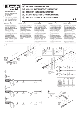
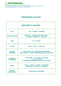
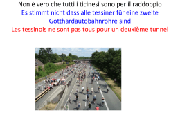
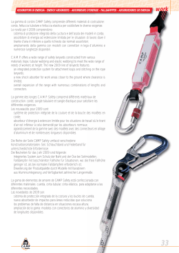
Montage- und
Bedienungsanleitung
JRGUMAT
Notice de montage et
d’utilisation
Istruzioni di
montaggio e d’uso
Installation and
operation instructions
Thermomischer
Mitigeurs
Termomiscelatore
Thermoblending valve
D 2 – 13
F 15 – 27
I 29 – 41
E 43 – 55
3400/3410
D
Montage- und Bedienungsanleitung
Bitte lesen Sie die vorliegende Montage- und
Bedienungsanleitung aufmerksam durch.
Die eingesetzten Symbole bedeuten:
Gefahr
Dieses Symbol weist auf ein hohes
Verletzungsrisiko für Personen hin.
Die Sicherheitshinweise müssen
beachtet werden.
Warnung
Dieses Symbol weist auf eine Information
hin, deren Nichtbeachtung zu umfangreichen Sachschäden führen kann.
Die Sicherheitshinweise sind zu beachten.
Hinweis
Dieses Symbol weist auf eine Information
hin, die wichtige Angaben hinsichtlich der
Verwendung enthält. Das Nichtbefolgen
kann zu Störungen führen.
Die Montage- und Bedienungsanleitung ist bei der
Anlagenübergabe der Bauherrschaft zu übergeben.
Technische Änderungen bleiben jederzeit vorbehalten.
I2
D
Einsatzbereich/Funktion
Die tausendfach bewährten JRGUMAT Thermomischer sind thermostatisch regelnde Mischventile,
die überall dort eingesetzt werden, wo eine konstante Mischwassertemperatur von hoher Regelgenauigkeit gewünscht und verlangt wird.
Zum Beispiel als Zentralmischer in Ein- und Mehrfamilienhäusern, Spitälern, Alters- und Pflegeheimen, Hotels, Kasernen, Duschanlagen von
Sportstätten, Industrie- und Gewerbebauten.
JRGUMAT Thermomischer dienen auch als Übertemperaturschutz in Alternativenergie-Anlagen,
wie Solar-Anlagen, Stückholzheizungen, Holzschnitzelfeuerungen, Pelletöfen, etc.
Dank der hohen Regelgenauigkeit werden
JRGUMAT Thermomischer auch für Spezialanwendungen, wie z.B. Temperaturhochhaltung
als Regulierorgane eingesetzt.
Der JRGUMAT Thermomischer ist ein proportional
regelnder Dreiwegmischer in offener Architektur.
Funktionen wie Rückflussverhinderung, Absperrung oder die Regulierung des Zirkulationsvolumenstroms können nicht durch den JRGUMAT
Thermomischer übernommen werden. Es sind
entsprechende Armaturen gemäss den Einbauschemas einzubauen.
3I
D
Einbauvorschriften
Der JRGUMAT Thermomischer funktioniert in jeder Einbaulage. Es sind die
Einbauvorschriften über den Wassererwärmer-Kreislauf, sowie die örtlichen
Normen einzuhalten. Es dürfen nur die
in den Schemas vorgeschriebenen Rückflussverhinderer eingebaut werden.
Als Absperrventile dürfen nur druckverlustarme Ventile, wie Schrägsitzventile,
Schieber und Kugelhahnen installiert
werden. Vor dem Einbau des JRGUMAT
Thermomischers sind die Leitungen
gründlich zu spülen. Um ein Fehlverhalten
des Mischers durch Strahlungswärme
zu verhindern, sollte der Mischer seitlich
des Erwärmers positioniert und ein Mindestabstand von einem Meter zwischen
Wassererwärmer und JRGUMAT eingehalten werden. Kann ein Mindestabstand
nicht eingehalten werden, muss ein
Thermosifon installiert werden.
Rückflussverhinderung
I4
Für den Anschluss der JRGUMAT Thermomischer dürfen nur druckverlustarme
Rückschlagventile JRG 1610-1615, Rückschlagklappen JRG 1682 und Rückflussverhinderer absperrbar JRG 5262-5284
verwendet werden.
D
Lötverschraubung
Während der Lötarbeit dürfen die Lötverschraubungen nicht am JRGUMAT Thermomischer angebracht sein, da sonst der
Thermostat und die Dichtungen beschädigt werden.
Warmwassertemperatur
Um eine einwandfreie Funktion des
JRGUMAT Thermomischers gewährleisten
zu können, muss die Warmwassertemperatur min. 5 K über der gewünschten
Mischwassertemperatur liegen. Ebenso
sind hydraulisch gleiche Verhältnisse am
Warm- und Kaltwassereingang zwingend.
Dies wird durch den Einbau des Mischers
in den Wassererwärmer-Kreislauf gemäss
unseren Einbauschemas gewährleistet.
Reparaturen
Am JRGUMAT Thermomischer dürfen
keine Reparaturen vorgenommen werden.
5I
D
Nomogramm
3
0,1
0,2
3
8 10
0,2
½
2
3
¾
1
600
10
1200
20
30 40 50 60 70
8 10
15 20
4 5 6
200 300
3
4 5
1¼ 1½ 2 DN 65 80
2
1
30 40 5060 80100
Volumenstrom V
20
0,3 0,4 0,5
GN
0,3 0,4 0,50,6 0,8 1
0,1
4 5 6
Sollwert-Toleranz ±1K
m
h
1500
1,2 1,5 2
10
8
6
5
0,02 0,03 0,04 0,05
20
40
30
100
80
60
200
400
300
1000
800
600
l
s
l
min
Sollwert-Toleranz ±2K
I6
Druckverlust Dp mbar
D
Nomogramm
Die bei der Rohrweitenbestimmung ermittelte Rohrdimension gilt auch als Nennweite DN für den
JRGUMAT Thermomischer. Aus dem Nomogramm
können die Beziehungen zwischen Volumenstrom,
Nennweite und Druckverlust entnommen werden.
Im rasterhinterlegten Bereich (siehe Seite 6)
herrschen optimale Betriebsbedingungen.
Geräuschverhalten
Dimension
Armaturengruppe
GN ½ DN 15 GN ¾-1¼ DN 20-32
I
II
Transportverpackung = Wärmedämmung
Die Transportverpackungen der JRGUMAT Thermomischer dienen nach der Montage und Einregulierung als Wärmedämmung.
7I
D
1
D
Funktion
E
F
3
Zirkulation
1
A
B
C
5
4
Kaltwasser
1
Standardtemperatur
°C
25
40
48
55
2
2
Mischwasser
Warmwasser
6
2
Einstellbereiche
°C
20-30
30-45
36-53
45-65
A Thermostat
B Ventilschieber, Rotguss,
beschichtet
C Bolzen, Chromnickelstahl
1 Gehäuse, Rotguss
2 Regulierschieber, Rotguss
3 Einstellschraube, Messing
4 Kaltwassersitz,
Chromnickelstahl
5 Warmwassersitz, Rotguss
6 Zirkulationstülle, Kunststoff
Änderung der Mischwassertemp.
bei 1 Schlüsselumdrehung
GN ½-1 GN 1¼-2
DN 15-25 DN 32-50 DN 65/80
ca. 6 K
ca. 4 K
ca. 2 K
D
Werkeinstellung/Umstellung
JRGUMAT Thermomischer sind mit einem der
Standardtemperatur zugeordneten Thermostaten
ausgerüstet und vom Werk auf eine Standardtemperatur eingestellt. Diese ist aus der Artikelnummer ersichtlich, im Zentrum des Temperaturschildes D und auf der Verpackung angegeben.
Eine Änderung der Standardtemperatur darf nur
innerhalb der Grenzen des zugeordneten Mischwassereinstellbereiches erfolgen. Dabei wird
folgendermassen vorgegangen: Mit dem Sechskantstiftschlüssel E wird das Temperaturschild D
im Zentrum durchstochen. Durch das Drehen der
Schraube F im Uhrzeigersinn wird die Mischwassertemperatur erhöht und im Gegenuhrzeigersinn
herabgesetzt. Dabei muss der Volumenstrom im
rasterhinterlegten Feld „Sollwert-Toleranz ± 1K“
liegen (siehe Nomogramm Seite 6).
Wird der Mischer in ein Zirkulationsnetz eingebaut,
ist die Zirkulation bei „Nullentnahme“ separat
einzuregulieren. Hierfür wird erst der Gesamtvolumenstrom der Pumpe (100%) einreguliert.
Anschliessend die Volumenströme, welche auf
den Mischer führen und der Anteil zur Wärmeverlustdeckung auf den Speicher einstellen.
Eine gut einregulierte Zirkulation hält die gewünschte Mischwassertemperatur konstant,
auch wenn kein Mischwasser bezogen wird.
9I
D
Mischwasser-Installationsbeispiele
DIN Text
TWK – Kaltwasser – WKR
TWW – Warmwasser – WWV
TWZ – Zirkulation WW – WWR
TWM – Mischwasser – WMV
WMZ– Zirkulation WM – WMR
JRGUMAT Thermomischer
Absperrventil
Rückschlagventil
Rückflussverhinderer absperrbar
Rückschlagkappe
Sicherheitsventil
Regulierorgan
JRGUTHERM Zirkulationsregler
Pumpe
Entleerhahn
JRG Nr. SIA
3400
5200-34
1610-15
5262-84
1682
1020-30
6310
6320
6000-12
Ohne Zirkulation mit Heisswasser-Abgang
D
Mit Zirkulation und Heisswasser-Abgang
ThermischeRegelung
MechanischeRegelung
Mit Zirkulation und thermischer Desinfektion
1. Hinweis: Um eine thermische Desinfektion gewährleisten zu können,
muss jede Zapfstelle durchflossen, bzw. gespült werden.
2. Hinweis: Für die thermische Desinfektion muss ausreichend heisses
Wasser zur Verfügung stehen.
Verbrühungsgefahr
Während der
Desinfektion ist
der Verbrühungsschutz nicht
gewährleistet!
M
Thermische Desinfektion
nur mit JRG LegioTherm
2T, JRG Nr. 3600 möglich.
Regelung für die Speicherladung
1
2
3
4
Kaltwassereing.
Warmwassereing.
Mischwasserausg.
Zirkulationseing.,
verschlossen
1
Δt = 5K
WP
3
2
4
11 I
D
Inbetriebnahme
Vor der Inbetriebnahme des JRGUMAT Thermomischers sind die Leitungen gründlich zu spülen.
Mit der Inbetriebnahme der Installation ist der
Mischer betriebsbereit.
Wartung
Der JRGUMAT Thermomischer ist wartungsfrei.
Am JRGUMAT Thermomischer dürfen keine
Reparaturen vorgenommen werden.
Betriebsstörungen
Bei allfällig auftretenden Betriebsstörungen
wenden Sie sich bitte an Ihren Sanitär-Installateur.
Vergleichen Sie die Einbausituation mit den Beispielen.
Prüfen Sie, ob die gewünschte Mischwassertemperatur bei genügender Entnahme nicht erreicht wird,
oder ob die Temperatur im Ruhezustand schwankt.
In diesem Falle ist evtl. die Zirkulation ungenügend
einreguliert.
I 12
D
Verschraubungen/Dichtungen
Die JRGUMAT Thermomischer dürfen
nur mit flachdichtenden, original JRG
Verschraubungen/Dichtungen angeschlossen werden.
AFM 34-Dichtungen dürfen nicht geölt
oder gefettet werden.
Fragen?
Für Fragen und anwendungstechnische Auskünfte
wenden Sie sich an unsere technische Berater oder
an den technischen Kundendienst.
6320
3500/3510
JRGUTHERM
Zirkulationsregler
JRGUMAT
Kompaktmischwasseranlage
3600
JRG LegioTherm 2T
Zirkulationsregler
Verlangen Sie unsere detaillierten Unterlagen. 13 I
I 14
JRGUMAT
Notice de montage et
d’utilisation
Mitigeurs
F 15 – 27
3400/3410
15 I
F
Notice de montage et d‘utilisation
Veuillez lire attentivement la présente notice de
montage et d‘utilisation. Voici la signification des
symboles utilisés:
Danger
Ce symbole indique la présence d‘un
risque élevé de blessures à des personnes.
Les indications de sécurité doivent être
observées.
Avertissement
Ce symbole indique qu‘il s‘agit d‘une
information dont le non respect pourrait
causer des dommages matériels importants. Les indications de sécurité doivent
être observées.
Note
Ce symbole indique qu‘il s‘agit d‘une
information contenant des indications
importantes sur l‘utilisation de l‘appareil.
Son non respect est susceptible de
provoquer des dérangements.
La notice de montage et d’utilisation doit être
remise au maître d’ouvrage au moment de la
remise de l’installation.
Toutes modifications techniques demeurent
réservées en tout temps.
I 16
F
Domaine d‘utilisation/fonctionnement
Les mitigeurs thermiques JRGUMAT ont fait leurs
preuves des milliers de fois. Ce sont des vannes mélangeuses à régulation thermique qui s‘emploient
partout où l‘on désire ou l‘on exige de l‘eau mitigée
à température constante avec un haut degré de précision du réglage. Exemples d‘utilisation: mitigeur
central dans les habitations individuelles ou collectives, hôpitaux, maisons de retraite et de repos, hôtels,
casernes, installations de douche d‘établissements
sportifs, bâtiments industriels ou commerciaux.
Les mitigeurs JRGUMAT servent aussi de protection
contre les températures excessives dans les équipements à énergies alternatives tels que panneaux
solaires, chauffages à plaquettes de bois, chaudières
à copeaux, fours à pellets, etc. Grâce à la haute précision du réglage de la température, les mitigeurs thermiques JRGUMAT conviennent également à l‘emploi
dans des application spéciales telles que le maintien
à température élevée en tant qu‘organe de régulation.
Le mitigeur thermique JRGUMAT est un mélangeur à
trois voies à régulation proportionnelle d‘architecture
ouverte. Les fonctions telles que l‘anti-retour, la fermeture ou la régulation du flux volumique circulant
ne peuvent pas être assumées par le mitigeur thermique JRGUMAT. En cas de besoin, il y a lieu de poser
les équipements correspondants conformément aux
schémas de montage.
17 I
F
Prescriptions de montage
Le mitigeur thermique JRGUMAT fonctionne dans toutes les positions de montage.
Il y a lieu de respecter les prescriptions de
montage sur le circuit du chauffe-eau ainsi
que les normes applicables au plan local.
Seuls les soupapes de retenue indiquées
dans les schémas peuvent être montées.
Comme vannes d‘arrêt, seules peuvent être
utilisées les vannes à faible perte de pression telles que les vannes à siège oblique,
les vannes à coulisseau et les robinets
sphériques. Les conduites doivent être
complètement rincées et purgées avant le
montage du mitigeur thermique JRGUMAT.
Afin d‘éviter tout défaut de fonctionnement
du mitigeur en raison de chaleur rayonnée,
celui-ci doit être installé à côté du chauffeeau et à au moins un mètre de distance
entre le mitigeur JRGUMAT et le chauffeeau. Si une distance minimale ne peut pas
être respectée, il convient d‘installer un
thermosiphon.
Anti-retour
I 18
Seuls des vannes anti-retour à faible chute
de pression JRG 1610-1615, clapets antichocs JRG 1682 et vannes anti-retour pouvant être fermée JRG 5262-5284 peuvent
être utilisées pour le raccordement du mitigeur thermique JRGUMAT.
F
Filetages soudés
Pendant les travaux de soudure, les raccords soudés ne doivent pas être fixés au
mitigeur thermique JRGUMAT, au risque
d‘endommager le thermostat et les joints.
Température de l‘eau chaude
Afin d‘assurer le fonctionnement impeccable du mitigeur thermique JRGUMAT,
la température de l‘eau chaude doit être
d‘au moins 5 °K au-dessus de la température désirée pour l‘eau mitigée.
De même, les conditions hydrauliques
doivent être les mêmes à l‘arrivée d‘eau
chaude et à l‘arrivée d‘eau froide, ce dont
on s‘assurera en procédant au montage
du mitigeur dans le circuit du chauffe eau
comme indiqué dans les schémas de
montage.
Réparations
Il ne doit être procédé à aucunes réparations sur le mitigeur thermique JRGUMAT.
19 I
F
Nomogramme
0,1
0,2
3
8 10
0,2
½
2
3
¾
1
30 40 50 60 70
8 10
15 20
4 5 6
200 300
3
600
10
1200
20
4 5
1¼ 1½ 2 DN 65 80
2
1
30 40 5060 80100
Flux volumique V
20
0,3 0,4 0,5
GN
0,3 0,4 0,50,6 0,8 1
0,1
4 5 6
Tolérance pour la valeur de
consigne ±1K
m3
h
1500
1,2 1,5 2
10
8
6
5
0,02 0,03 0,04 0,05
20
40
30
100
80
60
200
400
300
1000
800
600
l
s
l
min
Tolérance pour la valeur de consigne ±2K
I 20
Chute de pression Δp mbar
F
Nomogramme
La dimension des tubes déterminées lors du calcul
du diamètre des tubes vaut également comme
diamètre nominal DN pour le mitigeur thermique
JRGUMAT. Les relations entre le flux volumique, le
diamètre nominal et la chute de pression peuvent
être tirées du nomogramme. La partie hachurée
dénote des conditions de fonctionnement optimales.
Comportement phonique
Dimension
Gr. de robinetterie
GN ½ DN 15 GN ¾-1¼ DN 20-32
I
II
Emballage de transport = Isolation thermique
Les emballages pour le transport des mitigeurs
thermiques JRGUMAT servent d’isolation thermique
après la pose et le réglage du mitigeur.
21 I
F
1
D
Fonctionnement
E
F
3
Circulation
1
A
B
C
5
4
Eau froide
1
Températur.
standard
°C
25
40
48
55
2
2
Eau mitigée
Eau chaude
6
2
Plages de
réglage
°C
20-30
30-45
36-53
45-65
A Thermostat
B Vanne à coulisseau,
en bronze, plaqué
C Axe, acier au chrome nickel
1 Boîtier, en bronze
2 Coulisseau de réglage,
en bronze
3 Vis de réglage, laiton
4 Base eau froide, acier au
chrome nickel
5 Base eau chaude, en bronze
6 Gaine de circulation, matière
synthétique
Modification de la températ. de
l'eau mitigée pour un tour de clé
GN ½-1 GN 1¼-2
DN 15-25 DN 32-50 DN 65/80
Env. 6 K
Env. 4 K
Env. 2 K
F
Réglages d‘usine/changement des réglages
Les mitigeurs thermiques JRGUMAT sont équipés
d‘un thermostat affecté à une température standard
et réglé d‘usine à une température standard.
Celle-ci est indiquée par le numéro d‘article, au
centre de la plaquette de température D et sur
l‘emballage. Toute modification de la température
standard ne peut intervenir que dans les limites
de la plage de réglage de la température de l‘eau
mitigée.
Procéder comme suit: à l‘aide de la clé mâle à six
pans E, percer en son centre la plaquette de
température D. La température de l‘eau mitigée
est augmentée en tournant la vis F dans le sens
des aiguilles d‘une montre, et abaissée en tournant
dans le sens contraire. Il faut ce faisant que le flux
volumique se situe dans la zone hachurée
« Tolérance pour la valeur de consigne ± 1 K »
(voir le nomogramme).
Si le mitigeur est monté dans un réseau de circulation, il y a lieu de régler séparément la circulation
à « prélèvement zéro ». Pour ce faire, on commence
par régler le flux volumique total de la pompe
(100 %). On règle ensuite les flux volumiques
menant au mitigeur et la part de couverture de la
perte thermique de l‘accumulateur. Une circulation
bien réglée maintient constante la température de
l‘eau mitigée, même en l‘absence de prélèvement.
23 I
F
Exemple d‘installation pour l‘eau mitigée
DIN Texte
TWK – Eau froide – WKR
TWW – Eau chaude – WWV
TWZ – Circulation WW – WWR
TWM – Eau mitigée – WMV
WMZ– Circulation WM – WMR
Mitigeur JRGUMAT
Vanne d'arrêt
Vanne de retenue
Soup. de ret. avec disp. d'arrêt
Clapet de retenue
Soupape de sécurité
Té de réglage
Régulateur de circ. JRGUTHERM
Pompe
Vanne de vidange
No. JRG SIA
3400
5200-34
1610-15
5262-84
1682
1020-30
6310
6320
6000-12
Sans circulation, avec sortie eau chaude
F
Avec circulation et sortie eau chaude
Régulation
thermique
Régulation
mécanique
Avec circulation et désinfection thermique
Note 1:
Note 2:
Afin de pouvoir assurer la désinfection thermique, chaque
point de prélèvement doit être rincé ou purgé.
Il faut disposer de suffisamment d'eau chaude pour pouvoir
assurer la désinfection thermique.
Risque de brûlure
La protection contre
les brûlures n'est pas
assurée pendant
la désinfection
thermique!
M
La désinfection thermique
à l'aide de l'appareil
JRG LegioTherm 2T,
no. JRG 3600 possible.
Régulation pour la charge de l‘accumulateur
1
2
3
4
Arr. de l'eau froide
Arr. de l'eau chaude
Sort. de l'eau mitig.
Entrée de la circulation: fermée
1
Δt = 5K
WP
3
2
4
F
Mise en service
Il y a lieu de rincer à fond les conduites avant la
mise en service du mitigeur thermique JRGUMAT.
Le mitigeur thermique est prêt à fonctionner dès
la mise en service de l‘installation.
Maintenance
Le mitigeur thermique JRGUMAT est exempt
d‘entretien. Aucunes réparations ne doivent être
effectuées sur les mitigeurs thermiques JRGUMAT.
Dérangements
Veuillez vous adresser à votre installateur sanitaire
en cas de dérangements dans le fonctionnement du
mitigeur.
Comparez la situation effective de montage avec
les exemples. Vérifiez, si la température désirée
de l‘eau mitigée n‘est pas obtenue en présence de
prélèvement suffisant, si la température varie au
repos. Dans ce cas, il est possible que la circulation
soit mal réglée.
I 26
F
Filetages/Joints
Les mitigeurs thermiques JRGUMAT
ne doivent être raccordés qu‘avec des
filetages et joints étanches plats JRG
d‘origine.
Les joints AFM 34 ne doivent être ni
huilés, ni graissés.
Avez-vous des questions?
N‘hésitez pas à vous adresse à nos conseillers techniques ou à notre service technique après-vente
si vous avez des questions ou si vous désirez des
renseignements techniques d‘application.
6320
3500/3510
JRGUTHERM
Régulateur
de circulation
JRGUMAT
Installation
compacte
d‘eau
mitigée
3600
JRG LegioTherm 2T
Régulateur de circulation
Demandez notre documentation détaillée.
27 I
I 28
JRGUMAT
Istruzioni di
montaggio e d’uso
Termomiscelatore
I
29 – 41
3400/3410
29 I
I
Istruzioni per il montaggio e l’uso
Vi preghiamo di leggere attentamente le presenti
istruzioni per il montaggio e l’uso. I simboli impiegati nel testo hanno i significati seguenti:
Pericolo
Questo simbolo segnala un alto rischio
di lesioni alle persone. Attenersi alle
istruzioni relative alla sicurezza.
Avvertimento
Questo simbolo segnala un’informazione,
la mancata osservanza della quale può
causare importanti danni alle cose.
Attenersi alle istruzioni relative alla
sicurezza.
Avviso
Questo simbolo segnala un’informazione
contenente importanti dati relativi
all’impiego. La mancata osservanza può
causare guasti.
Le Istruzioni per il montaggio e l’uso vanno consegnate al committente al momento della consegna
dell’impianto.
Con riserva di modifiche tecniche in qualsiasi
momento.
I 30
I
Campo d’applicazione/Funzione
I termomiscelatori JRGUMAT, collaudati migliaia di
volte, sono valvole miscelatrici per la regolazione termostatica, impiegabili dappertutto dove è desiderata
e pretesa una temperatura dell’acqua miscelata con
un’alta precisione di regolazione.
Per esempio, come miscelatori centrali in case monoe plurifamiliari, ospedali, case per anziani e di cura,
alberghi, caserme, impianti docce per installazioni
sportive, edifici industriali e artigianali.
I termomiscelatori JRGUMAT servono anche da protezione termica negli impianti di energia alternativa,
come: impianto solari, riscaldamenti a legna di
piccola pezzatura, bruciatori a scarti di legno, forni a
pellet, ecc. Grazie all’alta precisione di regolazione,
i termomiscelatori JRGUMAT sono usati anche in
applicazioni speciali, come per es. come organi di
regolazione per mantenere l’alta temperatura.
Il termomiscelatore JRGUMAT è un miscelatore a tre
vie per la regolazione proporzionale in architettura
aperta. Funzioni come antiriflusso, bloccaggio oppure
la regolazione di circolazione della portata in volume
non possono invece essere affidate ai termomiscelatori JRGUMAT. Per queste funzioni, occorre installare
le rubinetterie idonee conformemente agli schemi
d’installazione.
31 I
I
Prescrizioni per l’installazione
Il termomiscelatore JRGUMAT funziona in
qualsiasi posizione è installato. Attenersi
alle prescrizioni relative al circuito degli
scaldaacqua, come pure le norme locali.
Possono essere installati soltanto i dispositivi antiritorno prescritti dagli schemi.
Come valvole d’arresto si possono installare
unicamente valvole a minima perdita di
pressione, come quelle a sede obliqua,
otturatori e rubinetti a sfera.
Prima dell’installazione del termomiscelatore JRGUMAT occorre risciacquare a fondo
le condotte. Per impedire il funzionamento
errato del miscelatore in seguito a calore
radiante, occorre posizionarlo lateralmente
allo scaldaacqua, mantenendo almeno un
metro di distanza da esso. Una distanza
minima non può essere rispettata, deve
essere installato un termosifone.
Le istruzioni d’uso e di montaggio allegate
sono da rimettere al committente alla
consegna dell’impianto.
Dispositivi antiritorno
I 32
Per l’allacciamento dei termomiscelatori
JRGUMAT possono essere utilizzati unicamente valvole antiritorno a bassa perdita di
pressione JRG 1610-1615, valvole di ritegno
JRG 1682 e dispositivi antiritorno bloccabili
JRG 5262-5284.
I
Raccordo a vite saldato
Per i lavori di brasatura, i raccordi a vite
non devono essere montati sul termomiscelatore JRGUMAT, per evitare di danneggiare il termostato e le guarnizioni
di tenuta.
Temperatura dell’acqua calda
Per garantire il perfetto funzionamento
del termomiscelatore JRGUMAT occorre
che la temperatura dell’acqua calda sia
almeno 5 K sopra quella richiesta per
l’acqua miscelata.
Sono altrettanto coercitivi le stesse condizioni, dal punto di vista idraulico, per
le immissioni dell’acqua calda e fredda.
Il rispetto di queste condizioni è assicurato dall’installazione, conforme ai nostri
schemi d’installazione, del miscelatore
nel circuito dello scaldaacqua.
Riparazioni
È vietato procedere a riparazioni del
termomiscelatore JRGUMAT.
33 I
I
Nomogramma
0,1
0,2
3
8 10
0,2
½
2
3
¾
1
30 40 50 60 70
8 10
15 20
4 5 6
200 300
3
600
10
1200
20
4 5
1¼ 1½ 2 DN 65 80
2
1
30 40 5060 80100
Portata in volume V
20
0,3 0,4 0,5
GN
0,3 0,4 0,50,6 0,8 1
0,1
4 5 6
Tolleranza valore nominale ±1K
m3
h
1500
1,2 1,5 2
10
8
6
5
0,02 0,03 0,04 0,05
20
40
30
100
80
60
200
400
300
1000
800
600
l
s
l
min
Tolleranza valore nominale ±2K
I 34
Perdita di pressione Δp mbar
I
Nomogramma
La dimensione del tubo, stabilita determinando il
diametro delle condotte, vale anche come diametro
nominale DN per il termomiscelatore JRGUMAT.
Dal nomogramma si possono dedurre i rapporti fra
portata in volume, diametro nominale e perdita di
pressione. Nel settore retinato regnano condizioni
di funzionamento ottimali.
Rumorosità
Dimensione
Grup. rubinetterie
GN ½ DN 15 GN ¾-1¼ DN 20-32
I
II
Imballaggio di trasporto = Isolamento termico
Gli imballaggi per il trasporto dei termomiscelatori
JRGUMAT servono da isolamento termico dopo il
montaggio e l’aggiustamento.
35 I
I
1
D
Funzione
E
F
3
Ricircolo
B
1
A
C
5
4
Acqua fredda
1
Temperatura
standard
°C
25
40
48
55
2
Campi di
regolazione
°C
20-30
30-45
36-53
45-65
2
2
Acqua miscelata
Acqua calda
6
A Termostato
B Pistone della valvola,
bronzo, rivestita
C Perno, acciaio al nichel-cromo
1 Corpo della valvola, bronzo
2 Regolatore, bronzo
3 Vite di aggiustamento, ottone
4 Sede acqua fredda, acciaio
al nichel-cromo
5 Sede acqua calda, bronzo
6 Pressa acqua di ricircolo,
mat. plastica
Variazione della temp. acqua
miscelata con 1 giro di chiave
GN ½-1 GN 1¼-2
DN 15-25 DN 32-50 DN 65/80
ca. 6 K
ca. 4 K
ca. 2 K
I
Regolazione di fabbrica/Modifiche
I termomiscelatori JRGUMAT sono equipaggiati di
termostato correlato alla temperatura standard e
regolato in fabbrica su una temperatura standard.
Questa figura nel numero d’articolo, al centro della
targhetta della temperatura D ed è indicata anche
sull’imballaggio. Una modifica della temperatura
standard può avvenire unicamente entro i limiti
del campo di regolazione dell’acqua miscelata
correlato.
Per la modifica, procedere come segue: con la chiave
maschio esagonale E si perfora al centro la targhetta della temperatura D. Facendo ruotare la vite F in
senso orario, si aumenta la temperatura dell’acqua
miscelata, mentre ruotando la vite in senso antiorario, la temperatura diminuisce. Badare che la
portata in volume si situi nel campo retinato
“Tolleranza valore nominale ± 1K”
(vedere il nomogramma).
Se il miscelatore è installato in una rete di ricircolo,
occorre regolare separatamente il ricircolo su
“Prelievo zero”. A questo scopo, si aggiusta
dapprima la portata in volume complessiva della
pompa (100%).
In seguito, aggiustare sia le portate in volume
in arrivo al miscelatore, sia la quota per coprire
la perdita termica del bollitore. Un ricircolo ben
regolato mantiene costante la temperatura
dell’acqua miscelata, anche se non vi è prelievo
di quest’ultima.
37 I
I
Esempi d’installazione per acqua miscelata
DIN Testo
TWK – acqua fredda – WKR
TWW – acqua calda – WWV
TWZ – ricircolo WW – WWR
TWM – acqua miscelata – WMV
WMZ– ricircolo WM – WMR
Termomiscelatore JRGUMAT
Valvola d'arresto
Valvola antiritorno
Dispositivo antiritorno bloccabile
Valvola antiritorno
Valvola di sicurezza
Organo di regolazione
Regol. di ricircolo JRGUTHERM
Pompa
Rubinetto di scarico
JRG No. SIA
3400
5200-34
1610-15
5262-84
1682
1020-30
6310
6320
6000-12
Senza ricircolo con uscita acqua bollente
I
Con ricircolo e uscita acqua bollente
Regolazione
termica
Regolazione
meccanica
Con ricircolo e disinfezione termica
1a indicazione: per garantire la disinfezione termica, occorre che ogni
punto di prelievo sia risciacquato a fondo.
2a indicazione: per la disinfezione termica occorre che sia disponibile
una sufficiente quantità d'acqua.
Pericolo di scottature
Durante la disinfezione,
la protezione dalle
scottature non
è assicurata!
M
La disinfezione termica
è possibile soltanto con
JRG LegioTherm 2T,
JRG no. 3600.
Regolazione per caricare il serbatoio
1
2
3
4
Entrata acqua fredda
Entrata acqua calda
Uscita acqua miscel.
Entrata ricircolo,
chiusa
1
Δt = 5K
WP
3
2
4
I
Messa in esercizio
Prima di mettere in esercizio il termomiscelatore
JRGUMAT occorre risciacquare a fondo le condotte.
Con la messa in esercizio dell’installazione,
il miscelatore è pronto a entrare in funzione.
Manutenzione
Il termomiscelatore JRGUMAT non richiede
manutenzione.
È vietato procedere a riparazioni di qualsiasi
genere sul termomiscelatore JRGUMAT.
Guasti di funzionamento
In caso di guasti di funzionamento, rivolgetevi al
vostro installatore sanitario.
Comparate la situazione d’installazione con gli
esempi. Verificate se la voluta temperatura
dell’acqua miscelata non viene raggiunta con un
prelievo sufficiente, oppure se la temperatura varia
in condizione di riposo. In questo caso, vuol dire che
la circolazione è insufficientemente aggiustata.
I 40
I
Raccordi a vite/Guarnizioni di tenuta
I termomiscelatori JRGUMAT vanno
allacciati esclusivamente mediante
raccordi a vite/guarnizioni di tenuta a
piatto originali JRG.
Le guarnizioni AFM 34 non devono essere
lubrificate con olio o grasso.
Avete ancora delle domande?
Se avete ancora domande o vi occorrono informazioni relativi all’impiego, vi preghiamo di rivolgersi
ai nostri consulenti tecnici oppure al servizio tecnico
di assistenza ai clienti.
6320
3500/3510
Regolatore
di ricircolo
JRGUTHERM
Impianto
compatto
di miscelazione acqua
JRGUMAT
3600
Regolatore di ricircolo
JRG LegioTherm 2T
Richiedete le nostre documentazioni dettagliate.
41 I
I 42
JRGUMAT
Installation and
operation instructions
Thermoblending valve E 43 – 55
3400/3410
43 I
E
Installation and operating instructions
Please read these installation and operating
instructions carefully. The symbols used have
the following meanings:
Danger
This symbol indicates a serious risk of
personal injury. Please follow the safety
pointers given.
Warning
This symbol refers to information that can
result in serious material damage if not
followed. Please follow the safety pointers
given.
Note
This symbol refers to information that
contains important data relating to usage.
Failure to comply can lead to malfunctions.
The installation and operating instructions must be
given to the building owner when the installation is
commissioned.
The company reserves the right to amend product
specifications at any time.
I 44
E
Field of application/Function
JRGUMAT thermoblending valves are tried-andtested thermostatic mixing valves that are used
wherever a constant water temperature of high
controllable accuracy is required. For example,
as central mixing valves in family homes and
apartment buildings, hospitals, old-age and
nursing homes, hotels, barracks, showering
facilities at sports grounds, on commercial and
industrial premises. JRGUMAT thermoblending
valves can also be used to protect against excess
temperatures in alternative energy installations
such as solar-heating installations, log heating
systems, wood-chip heating systems, wood
pellet stoves and furnaces, etc. Thanks to their
high controllability, JRGUMAT thermoblending
valves are also used for special applications such
as, for example, maintaining high temperatures
as regulating units.
JRGUMAT thermoblending valves are proportionally
regulating, open architecture, three-way mixing
valves. JRGUMAT thermoblending valves cannot be
used as check valves or stop valves nor can they be
used to regulate flow rates. The appropriate valves
must be installed as shown in the layout drawings.
45 I
E
Installation instructions
JRGUMAT thermoblending valves will operate in any position. The installation regulations relating to the water heater circulation as well as local standards must be
complied with. Only the non-return valves
prescribed in the diagrams may be used.
The only stop valves permissible are low
pressure-loss valves, such as slanted seat
valves, gate valves and ball valves.
All pipes must be flushed thoroughly before JRGUMAT thermoblending valves are
installed. In order to prevent a JRGUMAT
mixing valve from malfunctioning due to
radiated heat, the valve should be located
at least one metre away from the heater.
If a minimum separation cannot be guaranteed, a thermosiphon must be installed.
Return-flow prevention
When connecting JRGUMAT thermoblending valves, only JRG type 1610-1615
low pressure-loss check valves, JRG type
1682 swing check valves and JRG type
5262-5284 closable non-return valves may
be used.
I 46
E
Soldering unions
When carrying out soldering work, it is
essential to remove a JRGUMAT thermoblending valve from the unions as the
thermostat and the seals would otherwise
be damaged.
Hot water temperature
To ensure that your JRGUMAT thermoblending valves operate correctly,
the warm water temperature must be at
least 5 K above the desired blended water
temperature. Identical hydraulic conditions are essential at the hot and cold
water feeds. This is ensured by installing
the mixing valves in the water heater
circuit as shown in our installation
drawings.
Repairs
No attempts should be made to repair
JRGUMAT thermoblending valves.
47 I
E
Nomogram
0,1
0,2
3
8 10
0,2
20
½
2
3
¾
1
Volume flow V
30 40 50 60 70
8 10
15 20
4 5 6
200 300
3
600
10
1200
20
4 5
1¼ 1½ 2 DN 65 80
2
1
30 40 5060 80100
0,3 0,4 0,5
GN
0,3 0,4 0,50,6 0,8 1
0,1
4 5 6
Setpoint value tolerance ±1K
m3
h
1500
1,2 1,5 2
10
8
6
5
0,02 0,03 0,04 0,05
20
40
30
100
80
60
200
400
300
1000
800
600
l
s
l
min
Setpoint value tolerance ±2K
I 48
Pressure drop Δp mbar
E
Nomogram
The size of piping used is considered the nominal
value DN for a JRGUMAT thermoblending valve.
The relationships between flow rate, nominal size
and pressure loss are given in the nomogram.
Optimum operating conditions are to be found in
the hatched area.
Noise behaviour
Dimension
Valve group
GN ½ DN 15 GN ¾-1¼ DN 20-32
I
II
Transport packaging = Thermal insulation
The transport packaging of every JRGUMAT
thermoblending valve is used as thermal insulation
following installation and adjustment.
49 I
E
1
D
Function
E
F
3
Circulation
1
A
B
C
5
4
Cold water
1
Standardtemperature
°C
25
40
48
55
2
2
Blended water
Warm water
6
2
Ranges of
adjustment
°C
20-30
30-45
36-53
45-65
A
B
C
1
2
3
4
Thermostat
Valve slide, gunmetal, coated
Pin, chromium-nickel steel
Body, gunmetal
Regulating gate, gunmetal
Adjusting screw, brass
Cold water seat, stainless
steel
5 Hot water seat, gunmetal
6 Circulation sleeve, plastic
Change in the blended water
temperature with 1 full key turn
GN ½-1 GN 1¼-2
DN 15-25 DN 32-50 DN 65/80
ca. 6 K
ca. 4 K
ca. 2 K
E
Factory setting/Changing
JRGUMAT thermoblending valves are fitted with
a thermostat allocated to a standard temperature
and set to a standard temperature at the factory.
This is apparent from the article number, it appears
in the centre of the temperature label D and is
indicated on the packaging. A change in standard
temperature can only be made within the limits
of the blended water adjustment range allocated.
Proceed as follows: Pierce the middle of the temperature label D with the Allen key E. Turning the
screw F clockwise will increase the blended water
temperature while turning the key counterclockwise
will lower it. The flow rate must be in the hatched
field “Nominal value tolerance ± 1K” (q.v. nomogramme).
If the mixing valve is installed in a circulation network, the circulation must be adjusted separately
at “zero removal”. To do this, the overall flow rate
of the pump (100%) must be adjusted first. Then
set the flow rates, which lead to the mixing valve
and set the proportion required to cover heat loss
on the water heater.
A well-regulated circulation keeps the desired
blended water temperature constant even if no
blended water is drawn off.
51 I
E
Typical blended water installations
DIN Text
TWK – cold water – WKR
TWW – hot water – WWV
TWZ – WW circulation – WWR
TWM – blended water – WMV
WMZ– WM circulation – WMR
JRGUMAT thermoblend. valve
Shut-off valve
Non-return valve
Backflow preventer with shut-off
Swing check valve
Safety valve
Adjusting socket
JRGUTHERM circul. flow regul.
Pump
Drain valve
JRG No. SIA
3400
5200-34
1610-15
5262-84
1682
1020-30
6310
6320
6000-12
Without circulation with separ. hot water outlet
E
With circulation and hot water outlet
Thermal
regulation
Mechanical
regulation
With circulation and thermal disinfection
1. Note: To be able to guarantee thermal disinfection, water must pass
through every connection or every connection must be flushed.
2. Note: Enough hot water must be available for thermal disinfection.
Danger of scalding
Anti-scald protection
is deactivated during
disinfection!
M
Thermal disinfection only
with JRG LegioTherm 2T,
JRG no.3600 possible.
Regulator for hot-water storage tank
1
2
3
4
Cold water inflow
Hot water inflow
Blend. water outflow
Circulation inflow,
closed
1
Δt = 5K
HP
3
2
4
53 I
E
Commissioning
The pipes must be flushed thoroughly before
commissioning a JRGUMAT thermoblending valve.
When the installation is commissioned, the mixing
valve is ready for use.
Maintenance
JRGUMAT thermoblending valves require no
maintenance. No attempts should be made to
repair JRGUMAT thermoblending valves.
Malfunctions
If your JRGUMAT thermoblending valve malfunctions
at any time, please contact your plumber.
Compare the installation with the examples. Check
whether the required blended water temperature is
not attained when enough is removed or whether
the temperature fluctuates when idle. In this case,
the circulation has not been adequately adjusted.
I 54
E
Unions/Gaskets
JRGUMAT thermoblending valves may
only be connected using flat-sealing,
genuine JRG unions/gaskets.
AFM 34 seals may not be lubricated with
oil or grease.
Questions?
For questions and application-related requests for
information, please apply to our technical advisors
or to the technical after-sales service.
6320
3500/3510
JRGUTHERM
circulation
flow regulator
JRGUMAT
compact
blending
facility
3600
JRG LegioTherm 2T
circulation flow regulator
Detailed documentations available on request.
55 I
Georg Fischer JRG AG
Hauptstrasse 130, CH-4450 Sissach
Phone +41 (0)61 975 22 22, Fax +41 (0)61 975 22 00
www.jrg.ch, [email protected]
Georg Fischer JRG SA
Via Boscioro 20, CH-6962 Viganello/Lugano
Phone +41 (0)91 972 26 26, Fax +41 (0)91 972 26 27
www.jrg.ch, [email protected]
Georg Fischer JRG GmbH
Nördliche Grünauerstrasse 65
D-86633 Neuburg/Donau
Phone +49 (0)8431 5817-0, Fax +49 (0)8431 5817-20
www.jrg.de, [email protected]
Einbaudatum: Date de montage: Data d‘installazione: Built-in date:
Ihr Installateur: Votre installateur: Il vostro installatore: Your plumber:
Ident.-Nr. 09 458 09 / 2.10 / 10 / SMS
Scarica