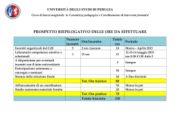
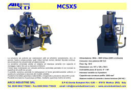
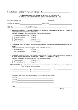
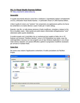
I GB Release: 2.4 Date: April 2006 Uniflair persegue una politica di costante innovazione tecnologica riservandosi il diritto di variare senza preavviso le caratteristiche qui riportate. Uniflair policy is one of continuos technological innovation and the Company therefore reserves the right to amend any data herein without prior notice. Famiglia Tipo di unità M: monoblocco Modello Numero di Compressori A: raffreddamento meccanico F: raffredd. mecc. +free-cooling Versione C: Versione base T: versione con riscald. elettrico Sistema di Controllo W: microprocess. tipo mP20 W M A 018 1 C W Family Units type Function mode Model Number of Compressors Version Control System M: Monobloc 4 Tipo di Funzionamento A: mechanical cooling F: mech. cooling +freecooling C: Basic version T: Version with electric re-heat W: mP20 microprocessor Le unità Uniflair Wall-mounted sono condizionatori autonomi monoblocco concepiti per essere installati sulla parete esterna di centrali telefoniche e locali tecnologici. Il condensatore integrato nella struttura della macchina consente di fornire le unità completamente assemblate e caricate di fluido refrigerante. In fabbrica sono tarati tutti i dispositivi di regolazione e di sicurezza per le normali condizioni di funzionamento e viene eseguito il collaudo elettrico e frigorifero. L'installazione si riduce ad un semplice collegamento elettrico e meccanico del condizionatore e può essere eseguita anche da personale non specializzato. Tutti gli organi interni sono ispezionabili e smontabili frontalmente, consentendo di eseguire tutte le operazioni di manutenzione completamente dall'esterno, senza la necessità di accedere al locale condizionato che potrebbe essere ad accesso controllato; nelle installazioni multiple le unità possono quindi essere affiancate con distanze minime. Le viti esterne per il fissaggio dei pannelli, in materiale inossidabile, sono antivandaliche e la loro rimozione è possibile solo attraverso l'utilizzo di appositi utensili. La doppia pannellatura esterna, disponibile in lamiera zincata e verniciata oppure in lega di alluminio, consente accesso differenziato al vano ventilatori e al vano compressori/quadro elettrico. In questo modo è possibile eseguire la manutenzione e le tarature della macchina senza interromperne il funzionamento Uniflair Wall-Mounted air conditioners are autonomous monobloc units designed to be fitted on the outside wall of the air conditioned room (telephone exchanges and other technological environments). DESCRIZIONE GENERALE GENERAL DESCRIPTION SCOCCA portante in lamiera zincata provvista di flangiatura perimetrale per il fissaggio sulla parete esterna del locale da condizionare. PANNELLI ESTERNI in lamiera da 1.2 mm, verniciati con polveri epossidiche bianco crema (RAL 9001), rivestiti con materiale fonoassorbente e termoisolante resistente all'abrasione e autoestinguente. VITI ANTIVANDALICHE DI TIPO 'TORX' per limitare l'accesso ai componenti interni della macchina al solo personale autorizzato. FILTRO in materiale autoestinguente con efficienza EU2 (doc Eurovent 4-5), provvisto di telaio metallico rigido. VENTILATORE CENTRIFUGO CON PALE CURVE INDIETRO. SENSORE DEL FLUSSO D'ARIA per attivare lo stato di allarme con portata d'aria insufficiente. BATTERIA DI RAFFREDDAMENTO sottoposta a trattamento idrofilico, ad ampia superficie frontale costruita con tubi di rame meccanicamente espansi su alette di alluminio, provvista di vaschetta in acciaio inossidabile con tubo flessibile per drenare la condensa. RISCALDAMENTO ELETTRICO (nelle versione TW) a resistenze alettate in alluminio complete di termostato di sicurezza per inibire l'alimentazione e attivare l'allarme in caso di surriscaldamento. QUADRO ELETTRICO alloggiato in un vano separato dal flusso dell'aria, conforme alle vigenti direttive CEE e con: - trasformatore ausiliario a 24 V; - interruttore-sezionatore generale; - protezioni magnetotermiche; - teleruttori di comando. COMPRESSORE ERMETICO SCROLL ad alta efficienza energetica e basso livello sonoro con protezione termica incorporata. CIRCUITO FRIGORIFERO comprendente: - filtro deidratore e spia di flusso; - valvola termostatica d’espansione; - pressostati di alta e bassa pressione (il primo con ripristino manuale). CONTROLLO A MICROPROCESSORE TIPO mP20; questo controllo comprende i sensori di temperatura ambiente, di temperatura esterna e di temperatura dell’aria di mandata (standard su WMF). DISPOSITIVO DI RAFFREDDAMENTO GRATUITO (solo nella versione WMF): vedi descrizione successiva. SELF-SUPPORTING CABINET in galvanised steel complete with flange for fixing to the external wall of the air conditioned room. EXTERNAL PANELS in 1.2 mm sheet painted with cream epoxy powder (RAL 9001) and lined with scratch-resistant self-extinguishing sound absorbing insulating material. ANTI-TAMPER SCREWS to protect against unauthorised access to the internal components of the unit. The built-in air cooled condenser means that units can be supplied fully assembled and pre-charged with refrigerant. All components are factory-set for normal operating conditions and cooling and electrical circuits are fully tested before delivery. Installation is therefore simply a question of electrical and mechanical connections which can be done even by nonspecialised personnel. The internal layout of the unit allows easy inspection and maintenance of all components from the outside, an important factor since the air conditioned room may have restricted access for security; in multiple installations the units can therefore be installed side by side. The external fixing screw are rust-proof and have anti-tamper heads. It is only possible to remove them with the special tool supplied. The double external panelling, available in either painted galvanised steel or aluminium alloy, gives separate access to the fan section and to the compressor/electrical panel. It is therefore possible to inspect and carry out maintenance on the unit without interrupting operation. FILTER in self-extinguishing material with EU2 efficiency (doc. Eurovent 4-5) fitted in rigid metal frame. EVAPORATING FAN: centrifugal fan with backward curved blades. AIRFLOW SENSOR for activating an insufficient airflow alarm. COOLING COIL hydrophilic-treated, with large frontal area, in copper tubing mechanically expanded into aluminium fins; stainless steel condensate drain tray with flexible tube. ELECTRICAL RE-HEAT (in version ...TW) with aluminium finned elements and safety thermostat for power supply cut off and alarm activation in the event of overheating. ELECTRICAL PANEL conforming to CEE directives and housed in a compartment isolated from the airflow: • auxiliary 24V transformer; • mains switch; • magnetothermal protection; • contactors. HERMETIC SCROLL COMPRESSORS with high energy efficiency and low noise operation with built-in thermal protection. REFRIGERANT CIRCUIT including: • filter-dryer and liquid sight glass; • thermostatic expansion valve; • low and high- pressure pressostats (HP with manual reset). mP20 MICROPROCESSOR CONTROL; including room, external and delivery temperature sensors (standard in WMF version). FREE-COOLING SYSTEM (only in WMF version). See description below. 5 ACCESSORI OPTIONAL ACCESSORIES PANNELLI ESTERNI: le unità sono tutte disponibili a richiesta con pannelli esterni in alluminio. TERMINALE UTENTE mP20 per l’impostazione e la visualizzazione dei parametri di funzionamento dell’unità. GRIGLIE DI RIPRESA E DI DISTRIBUZIONE DELL'ARIA IN AMBIENTE (quest'ultima a doppio ordine di alette). SENSORE DI ALLARME DI FILTRO ARIA INTASATO, consistente in un pressostato di controllo dello stato di sporcamento del filtro. CONDENSATORI ELETTRICI DI RIFASAMENTO per mantenere il fattore di potenza elettrico (cos ϕ) superiore a 0,9. SCHEDA OROLOGIO per la gestione degli eventi storici e temporali della macchina. SCHEDA LAN per connessione in rete locale. SCHEDA LAN+OROLOGIO. USCITA SERIALE RS485 per la trasmissione dei dati ad un sistema di supervisione centralizzato. DOPPIA ALIMENTAZIONE ELETTRICA: tensione di rete per il normale funzionamento dell'unità ed alimentazione da UPS 230V/1N/50Hz per il funzionamento in emergenza limitato a ventilatore evaporante, condensante, controllo a microprocessore e servomotore della serranda; DOPPIA ALIMENTAZIONE ELETTRICA CON ALIMENTAZIONE A 48Vdc DA INVERTER E VENTILATORI ALIMENTATI IN CORRENTE CONTINUA: tensione di rete per il normale funzionamento dell'unità ed alimentazione da UPS 48Vdc per il funzionamento in emergenza limitato a ventilatore evaporante, controllo a microprocessore e servomotore della serranda; R407C: realizzazione con refrigerante ecologico. FILTRO con efficienza EU4 (doc Eurovent 4-5). SENSORE di temperatura ed umidità ambiente. REGOLATORE DELLA VELOCITÁ DEL VENTILATORE DEL CONDENSATORE con sonda di pressione. SERVOMOTORE CON RITORNO A MOLLA. EXTERNAL PANELS: units are also available with aluminium external panels mP20 USER TERMINAL for the setting and display of unit function parameters INTAKE AND DISCHARGE GRILLE FOR DISTRIBUTION OF THE AIR IN THE ENVIRONMENT with two rows of slats. BLOCKED AIR FILTER ALARM SENSOR: dirty filter control pressostat. INTAKE AND ELECTRICAL POWER FACTOR CORRECTION CONDENSERS for maintaining the electrical power factor (cos. ϕ) over 0,9. CLOCK CARD for the management of time and date events LAN CARD for connection of units in Local Area Network. LAN + CARD CARD. RS485 SERIAL OUTPUT for the transmission of data to a centralised supervision system DOUBLE ELECTRICAL POWER SUPPLY - normal function uses mains power, emergency function uses UPS 230V/1N/50Hz for the fan, microprocessor control and free- cooling damper DOUBLE ELECTRICAL POWER SUPPLY WITH 48V DC FROM INVERTER and DC FANS: normal function uses mains power, emergency function uses UPS 48V DC for evaporator fan, microprocessor control and free-cooling damper motor R407C: these units are available in versions for operation with HCFC-R22 (standard) and environment-friendly HFC-R407C. EU4 FILTER (doc. Eurovent 4-5). SENSOR for room temperature and humidity. VARIABLE CONDENSER SPEED FAN with pressostat probe. SPRING-RETURN DAMPER. DISPOSITIVO DI RAFFREDDAMENTO GRATUITO(((solo nella versione WMF) FREE COOLING MECHANISM (only on WMF version) Il ciclo di raffreddamento gratuito consiste nell’introduzione in ambiente di aria esterna quando questa sia sufficientemente fredda per smaltire il carico termico del locale. L’unità è provvista di una serranda a farfalla e di due prese d’aria in aspirazione: • presa di aria di ricircolo (rappresentata nelle illustrazioni sulla destra); • presa di aria esterna (rappresentata nelle illustrazioni sulla sinistra). The free cooling cycle consists of the introduction into the room of external air when this is sufficiently cold to absorb the thermal load of the room. The unit is fitted with a butterfly damper and two air intakes: • recycled air intake; • external air intake. A. FUNZIONAMENTO NORMALE (Fig. a) Durante il funzionamento normale la serranda è posizionata per aspirare solo aria dall’interno del locale (freccia sulla sinistra), chiudendo la presa d’aria esterna. L’aria aspirata viene inviata dal ventilatore verso la batteria di raffreddamento e quindi reintrodotta nel locale. Il raffreddamento avviene per mezzo del ciclo frigorifero (avviando il compressore) su comando del termostato. A. NORMAL FUNCTIONING (Fig. a) During normal function, the damper takes in air from the room only (arrow on the left), closing the external air intake. The fan sends air over the cooling coil and into the room. Cooling is via the cooling cycle (starting the compressor) and commanded by the thermostat. B. RAFFREDDAMENTO GRATUITO (Fig. b) Non appena l’aria esterna assume una temperatura sufficientemente bassa per poter mantenere la temperatura ambiente al valore voluto, la serranda commuta la propria posizione aspirando ed inviando nel locale aria esterna anzichè aria ricircolata. L’espulsione dell’aria (in quantità ovviamente uguale a quella introdotta) può essere eseguita dal ventilatore del condensatore oppure direttamente attraverso l’uscita dell’aria di condensazione (scarico libero dell’aria del circuito di condensazione). Durante il funzionamento con raffreddamento gratuito il compressore è spento. B. FREE COOLING (Fig. b) As soon as the external air is of a low enough temperature to maintain room temperature at the desired level, the damper changes position, delivering into the room external air instead of recycled. The discharging of air (obviously in the same quantities as that taken in) can be performed by the condenser fan or directly via the condensation air output (free discharge of condensation circuit air). During free cooling function, the compressor is off. 6 C. FUNZIONAMENTO MODULANTE (fig. c) Quando la temperatura atmosferica si abbassa ulteriormente, l’introduzione del 100% di aria esterna porterebbe ad un abbassamento eccessivo della temperatura di mandata dell’aria. Il sistema di controllo modula quindi la posizione della serranda miscelando aria esterna con aria ricircolata al fine di mantenere la temperatura interna al valore desiderato. In ogni caso, la temperatura di immissione dell’aria viene mantenuta sopra un valore minimo prestabilito. C. MODULATED FUNCTION (fig. c) When the external temperature falls further, the introduction of 100% external air would cause very low delivery air temperature. The control system therefore changes the position of the damper to mix external and recycled air to maintain the temperature in the room at the required level. In any case, the temperature of the air delivery temperature is maintained above a pre-set minimum. QUANTITÁ MINIMA DI ARIA DI RINNOVO E’ possibile prefissare una posizione di minima apertura della serranda per permettere l’aspirazione di una porzione di aria esterna in qualsiasi modo di funzionamento MINIMUM QUANTITY OF FRESH AIR It is possible to pre-set a minimum opening position on the damper to allow the taking in of a proportion of fresh air in any operating mode. (a) (b) (c) (a) (b) (c) 7 WM*0121-0331 a h g f d e b c I a) b) c) d) e) f) g) h) Flangiatura perimetrale di fissaggio Motoventilatore del condensatore Griglia di presa d’aria del condensatore Pannelli frontali di ispezione e manutenzione Griglia di presa dell’aria esterna (versione F) Calotta di protezione della griglia dell’aria esterna (versione F) Griglia di ripresa (opzionale) Griglia di mandata (opzionale) 8 GB a) b) c) d) e) f) g) h) Perimeter fixing flange Condenser fan Condenser air intake grille Frontal inspection / maintenance panels External air intake grille (F version) Protective cover for external air intake grille (F version) Intake grille (optional) Discharge grille (optional) CONTROLLO A MICROPROCESSORE mP20 MICROPROCESSOR CONTROL mP20 Il controllo a microprocessore mP20 gestisce in modo autonomo il funzionamento dell’unità. Il controllo è comprensivo di: The mP20 microprocessor management. The control includes: • • microprocessor control circuit; • user terminal (optional); • room temperature sensor; • external temperature sensor (WMF only); • delivery air temperature sensor. • scheda di controllo a microprocessore; gives autonomous unit terminale utente (opzionale); • sonda di temperatura ambiente; • sonda di temperatura esterna (solo WMF); • sonda di temperatura dell’aria di mandata; Il sistema di controllo sarà costituito da una scheda alloggiata sul quadro elettrico e da un terminale che costituirà l’interfaccia utente. Nella scheda di controllo a microprocessore sono residenti tutti gli algoritmi di controllo e la memorizzazione di tutti i parametri di funzionamento. Una volta programmata, la scheda può funzionare anche senza la presenza del terminale, permettendo il controllo dell’unità da un terminale remoto che può essere posto fino a 200 m di distanza dall’installazione della macchina. Un terminale utente può essere condiviso da più macchine. La scheda di controllo garantisce le seguenti funzioni: • Controllo della temperatura ambiente • Visualizzazione dell’umidità relativa in ambiente (con sonda di umidità opzionale) • Limite di massima umidità ambiente che, una volta raggiunto, impone la chiusura della serranda di free-cooling e forza il funzionamento del compressore (con sonda di umidità opzionale) • Gestione delle riscaldamento elettrico (opzionale) • Gestione degli allarmi • Gestione dello stand-by nel caso di collegamento elettrico di due unità • Sistema di allarmi completo con indicazione visiva e sonora • Contatti di segnalzione allarmi distinti per tipologia • Contatto di allarme generale programmabile per la segnalazione di allarmi specifici selezionabili • Ripartenza automatica al ripristino della tensione programmabile • Ritardo programmabile alla ripartenza (installazioni multiple) • Controllo degli spunti dei compressori (limitazione della frequenza di accensione) • Programmabilità del controllo remoto (telecontrollo o supervisione); • Controllo del limite minimo della temperatura dell’aria di mandata (WMF) • Password su 2 livelli di programmazione (taratura, configurazione hardware e software) • Uscita seriale RS485 (opzionale) • Orologio/datario (scheda opzionale) • Conteggio delle ore di funzionamento dei componenti più significativi • Programmazione della manutenzione con segnalazione esplicita delle operazione da fare • Memorizzazione degli ultimi 30 allarmi (con data ed ora se con la scheda orologio opzionale) The control system comprises a circuit board housed in the electrical panel and a user interface terminal. All the control algorithms and memorisation of function parameters are contained in the microprocessor. Once it has been programmed the circuit board can function without the user terminal, allowing the unit to be controlled by a remote terminal up to 200 m from the air conditioner. One terminal can be shared by several units. The control circuit provides the following functions: • control of room temperature; • reading of relative humidity via an optional humidity sensor in the room; • management of optional electrical heater; • management of alarms; • management of stand-by if two units are connected; • alarm system with visual and acoustic indicators; • signal contacts for each type of alarm; • automatic re-start with restoration of minimum tension; • programmable delay of re-start for multiple installations; • control of compressor activation (limiting start-up frequency); • programmable control (remote control or supervision); • control of minimum temperature limit of discharge air (WMF); • password for two programming levels (for setting and for hardware/software configuration); • RS485 serial output (optional); • time/Date circuit (optional); • main component run hour counter; • maintenance programming with explicit indications of operations to be carried out; • memorisation of the last 30 alarms (with date and time if optional time/date board is installed); 9 • Visualizzazione del tipo di funzionamento e degli organi accesi con scritte per esteso (con terminale utente opzionale) • Fasce orarie di accensione/spegnimento settimanali differenziate (con scheda orologio opzionale) Feriale - Prefestivo - Festivo • Ciclo di guardia con il quale la macchina rimane in posizione di attesa garantendo però che la temperatura ambiente sia mantenuta tra due limiti di alta e bassa temperatura (impostabili); e che l’umidità sia mantenuta al di sotto di un limite massimo (con l’opzione sonda di umidità interna) • Impostazione distinta dei set-point di raffreddamento e riscaldamento • Funzione override con la quale comandare manualmente il funzionamento dei componenti principali senza l’esclusione dell’eventuale controllo remoto • Algoritmo di controllo ottimizzato che misura costantemente la temperatura ambiente, esterna e di mandata per gestire nel modo migliore il funzionamento in espansione diretta ed in free-cooling. Il free-cooling intelligente permette di estendere il funzionamento con raffreddamento gratuito alla temperatura esterna più elevata in relazione alle condizioni di carico che in quel momento sono presenti nel locale da condizionare. • Gestione ottimizzata del free-cooling sulle due unità in caso di unità in stand-by per ottenere il maggiore risparmio energetico possibile • Immunità ai disturbi di natura elettromagnetica od elettrostatica conformemente a quanto prescritto nella direttiva CEE 89/336 • Il corretto funzionamento della scheda a microprocessore e del terminale utente è garantito solamente per temperature comprese tra i -10°C e +65°C. • Verbal visualisation of function type and of components in operation (with optional user terminal); • Weekly time bands for switching unit on/off (with optional clock board) including weekdays, weekends and holidays; • sleep mode: the unit remains in stand-by but maintains room temperature between two pre-set limits; • double set points (hot and cold); • override function for manual control of main components without the exclusion of the remote control (if fitted) • optimised control algorithm which constantly monitors the temperature of the room, of the air outside and of the discharge air in order to maximise the effectiveness and efficiency of both the direct expansion and the intelligent free cooling functions. This means that free cooling can start earlier and continue for longer and at higher external temperatures since they take into account the effective load conditions inside the air conditioned room; • optimised two unit free-cooling management with units in stand-by, giving maximum energy saving; • immunity to electromagnetic and electrostatic disturbance according to the CEE 89/336 directive; • correct functioning of the microprocessor board and user terminal is guaranteed for temperature between : -10°C ÷ 65°C. SEGNALAZIONI A DISTANZA DEGLI ALLARMI Per il riporto a distanza degli stati di allarme sono disponibili nella scheda di controllo a microprocessore i seguenti contatti puliti liberi da potenziale: 1. cumulativo indirizzabile; si può scegliere da tastiera quali allarmi possono essere esclusi 2. compressore 3. ventilatore 4. filtri sporchi 5. resistenze elettriche REMOTE SIGNALLING OF ALARMS The following potential-free clean contacts are available in the microprocessor control circuit for the remote signalling of alarms: 1. cumulative addressable: the alarms to be excluded can be selected from the keypad. 2. compressor 3. fan 4. dirty filters 5. electrical resistance FUNZIONI SPECIALI SPECIAL FUNCTIONS FREE-COOLING INTELLIGENTE INTELLIGENT FREE-COOLING E’ una funzione esclusiva che permette di operare la fase di risparmio energetico in forma dinamica massimizzando in ogni momento l’effettiva potenzialità del sistema e permettendo di raggiungere risparmi energetici ed economici di gran lunga superiori ai sistemi con free-cooling convenzionali a punto fisso. Il microprocessore mette in relazione il carico termico che in quel momento è presente nel locale condizionato con la temperatura esterna, elaborando la temperatura ottimale di inizio free-cooling. In questo modo la temperatura di inizio free-cooling non è fissa ma si “adatta” alle condizioni di carico che in quel momento sono presenti nel locale condizionato. This is an exclusive system which gives dynamic control of the energy-saving phase, maximising the performance of this function at all times. The result is the ability to provide much greater energy saving (and therefore economy of operation) than the common fixed-point free-cooling systems. The microprocessor compares the thermal load present at that moment in the air conditioned environment with the outside temperature, calculating the optimum temperature at which to start free-cooling. In this way the temperature at which free-cooling starts is not fixed but changes to adapt to the load conditions present at that moment in the air conditioned environment. Per particolari esigenze può essere richiesto di attivare il ciclo di raffreddamento a punto fisso o a differenziale fisso, in questo modo di funzionamento il free-cooling viene attivato quando la temperatura esterna scende sotto un valore fisso tarabile. Tale tipo di funzionamento non considera il carico del locale condizionato. If required by the client, the free cooling cycle can be activated at a fixed point, i.e. when the external temperature falls below a certain pre-set temperature. Under this system, the load in the air conditioned environment is not taken into consideration. 10 TELECONTROLLO Nel caso si debba asservire il funzionamento della monoblocco ad un quadro di controllo esterno (es. PLC), è possibile comandare il funzionamento dell’unità attraverso contatti puliti liberi da potenziale. Sono possibili i seguenti modi di controllo: 1. Comando remoto ON-OFF per l’accensione/spegnimento della macchina; il controllo a microprocessore gestisce autonomamente tutte le funzioni della macchina; 2. Comando ON-OFF di: Compressore Resistenze elettriche Ventilatore evaporatore REMOTE CONTROL If it is necessary to link the units to an external control panel, function can be controlled via potential-free contacts. The following control modes are available: 1. remote ON - OFF command: the microprocessor controls all unit functions; 2. ON - OFF command for: Compressor Electrical resistance Evaporator fan CICLO DI GUARDIA La funzione “CICLO DI GUARDIA”, se abilitata, controlla che la temperatura dell’ambiente condizionato non superi la soglia di bassa/alta temperatura. Nel caso di superamento di una di una delle due soglie di limite, la scheda a microprocessore assume il controllo della macchina per riportare il valore di temperatura entro i limiti voluti. Tale funzione consente di sopperire ad eventuali guasti del quadro esterno di comando. SETBACK FUNCTION (SLEEP MODE) When the units are off, the “SLEEP MODE” function ensures that room temperature stays within the pre-set limits. If the high/low limit is exceeded the microprocessor control steps in, switching on one or both of the units to bring conditions back inside the thresholds. This function protects against faults in the external control system. FASCE ORARIE Questo dispositivo, disponibile con la scheda orologio (opzionale), permette di impostare l’avviamento e lo spegnimento automatico delle macchine dell’unità su base temporale (funzionamento a fasce oraria). E’ possibile suddividere le fasce orarie per i giorni feriali, prefestivi e festivi. TIME SETTINGS This function, available with the optional clock circuit board, enables the setting of automatic start-up and switching off times of the units (time band function). It is possible to sub divide the time bands for weekdays, weekends and holidays GESTIONE DI DUE MACCHINE Nel caso di installazioni di due macchine è possibile collegare elettricamente le schede di controllo a microprocessore oppure attraverso linea seriale (scheda LAN opzionale) per gestire il funzionamento delle due macchine senza l’introduzione di un quadro esterno di gestione. Le schede di controllo possono gestire le seguenti situazioni: • una macchina in funzionamento e una macchina in stand by; • accensione della macchina di riserva nel caso di intervento di un allarme nell’unita in funzionamento; • rotazione su base temporale dell’unità in funzione per consentire la ripartizione del carico di lavoro sulle due macchine; • intervento della seconda macchina in caso di superamento di una soglia di temperatura impostabile dell’ambiente condizionato per sopperire ad eventuali picchi di carico. Tale funzione può essere disabilitata nei casi in cui, per problemi elettrici, non si voglia il funzionamento contemporaneo delle due unità. Nel caso di due macchine con free-cooling (WMF) sono schematizzate di seguito le fasi di funzionamento in relazione all’aumento della temperatura esterna e/o del carico termico: MANAGEMENT OF TWO UNITS If two units are installed it is possible to connect the two microprocessor controls electrically in order to manage the function of two units without an external management system. The control circuit manages the following situations: • one unit functioning and the other in stand-by • the switching on of the reserve unit if there is an alarm in the functioning unit; • the rotation on a time basis of which unit is functioning in order to divide the workload between the two; • the switching on of the second machine in the event that a pre-set temperature threshold is exceeded in room. This function can be disabled if, for electrical reasons, two units cannot function simultaneously. LOW Free-cooling Unit 1 Raffredd. meccanico Mechanical cooling Stand-By If two WMF free-cooling units are installed together the following function logic is applied as the outside temperature or the thermal load increases: temperatura esterna outdoor temperature Units1 + 2 Unit 2 Unit 1 Unit 2 HIGH Unit 1 Units 1 + 2 Unit 2 11 COOLING CAPACITY RESA FRIGORIFERA I GB RAFFREDDAMENTO MECCANICO MECHANICAL COOLING WMA0121 R22 DP - Pa Pvent - kW Portata d'aria FA - Text = 30°C TOT - kW 40% Text = 40°C 50% Text = 40°C 45% Text = 40°C 40% Text = 40°C 12 340 310 270 410 370 330 620 560 480 620 560 480 740 680 600 1240 1110 960 1460 1340 1200 2240 2000 1720 2240 2000 1720 2670 2430 2170 7.4 7.1 8.4 8.2 8.0 9.9 9.6 9.5 7.4 7.1 8.4 8.2 7.6 9.9 9.6 9.1 - kW 3.9 3.8 3.7 5.4 5.3 5.1 7.3 7.2 6.9 8.1 7.9 7.7 9.6 9.4 9.1 kW 3.9 3.8 3.7 5.4 5.3 5.1 7.3 7.2 6.9 8.1 7.9 7.4 9.6 9.4 8.9 - kW 3.7 3.7 3.5 5.2 5.1 4.9 7.1 6.9 6.7 7.8 7.6 7.3 9.2 9.0 8.8 kW 3.7 3.7 3.5 5.2 5.1 4.9 7.1 6.9 6.7 7.8 7.6 7.3 9.2 9.0 8.8 - kW TOT TOT TOT 3.6 3.5 3.4 5.0 4.9 4.8 6.8 6.6 6.4 7.5 7.3 7.0 8.9 8.7 8.5 kW 3.6 3.5 3.4 5.0 4.9 4.8 6.8 6.6 6.4 7.5 7.3 7.0 8.9 8.7 8.5 - kW TOT 4.2 4.1 4.1 5.8 5.7 5.6 7.7 7.6 7.5 8.7 8.6 8.4 10.3 10.1 10.0 kW 3.7 3.5 3.3 4.9 4.8 4.5 7.2 6.8 6.3 7.6 7.2 6.7 8.8 8.4 8.0 - kW 4.0 3.9 3.9 5.6 5.5 5.4 7.4 7.3 7.2 8.4 8.3 8.1 9.9 9.8 9.6 kW 3.6 3.5 3.2 4.9 4.7 4.4 7.1 6.7 6.2 7.4 7.0 6.5 8.7 8.3 7.8 - kW 3.8 3.7 3.7 5.3 5.3 5.2 7.1 7.0 6.9 8.0 7.9 7.8 9.5 9.4 9.3 kW 3.6 3.4 3.2 4.8 4.6 4.3 7.1 6.6 6.1 7.3 6.9 6.4 8.5 8.1 7.7 - kW 3.6 3.6 3.5 5.1 5.0 5.0 6.8 6.7 6.6 7.6 7.5 7.3 9.1 9.0 8.9 kW 3.5 3.3 3.1 4.7 4.5 4.3 6.8 6.4 5.9 7.2 6.7 6.2 8.4 8.0 7.6 - kW 10.5 10.4 10.2 TOT TOT TOT TOT 4.3 4.2 4.2 5.9 5.8 5.7 7.9 7.8 7.7 8.9 8.8 8.6 kW 4.1 3.9 3.6 5.4 5.2 4.9 7.9 7.4 6.9 8.3 7.8 7.3 9.7 9.2 8.7 - kW 4.1 4.0 4.0 5.7 5.6 5.6 7.7 7.5 7.4 8.6 8.5 8.3 10.1 10.0 9.9 kW 4.1 3.8 3.5 5.4 5.1 4.8 7.7 7.3 6.8 8.2 7.7 7.1 9.5 9.1 8.6 - kW 3.9 3.8 3.8 5.5 5.4 5.3 7.4 7.2 7.1 8.1 8.1 7.9 9.7 9.6 9.5 kW 3.9 3.7 3.5 5.3 5.0 4.8 7.4 7.2 6.7 8.1 7.6 7.0 9.4 8.9 8.4 - kW 3.7 3.7 3.6 5.2 5.2 5.1 7.1 6.9 6.7 7.8 7.7 7.5 9.3 9.2 9.1 kW 3.7 3.7 3.4 5.2 4.9 4.7 7.1 6.9 6.5 7.8 7.4 6.8 9.3 8.8 8.3 - kW TOT TOT TOT TOT 4.4 4.3 4.2 6.0 6.0 5.9 8.3 8.0 7.8 9.1 9.0 8.8 10.7 10.6 10.4 kW 4.4 4.3 3.9 6.0 5.7 5.4 8.3 8.0 7.5 9.1 8.6 7.9 10.7 10.1 - kW 4.2 4.1 4.0 5.8 5.8 5.7 8.0 7.8 7.5 8.8 8.6 8.5 10.4 10.2 10.1 kW 4.2 4.1 3.9 5.8 5.6 5.3 8.0 7.8 7.5 8.8 8.4 7.8 10.1 9.9 9.4 - kW 4.1 4.0 3.8 5.7 5.5 5.5 7.7 7.5 7.3 8.5 8.3 8.1 10.1 9.8 9.7 kW 4.1 4.0 3.8 5.7 5.5 5.2 7.7 7.5 7.3 8.5 8.3 7.6 10.1 9.8 9.2 - kW 3.9 3.8 3.7 5.5 5.3 5.2 7.4 7.2 6.9 8.1 7.9 7.7 9.7 9.5 9.3 3.9 3.8 3.7 5.5 5.3 5.2 7.4 7.2 6.9 8.1 7.9 7.5 9.7 9.5 9.1 TOT TOT TOT SENS DP Pvent FA Text TOT SENS 0,15 0,15 0,15 0,23 0,23 0,23 0,30 0,30 0,30 0,30 0,30 0,30 0,46 0,46 0,46 7.6 SENS Text = 45°C 100 7.6 SENS 28°C 50 5.1 SENS Text = 35°C 0 5.3 SENS Text = 30°C 100 5.4 SENS Text = 45°C 50 5.4 SENS 26°C 0 5.5 SENS Text = 35°C 100 5.5 SENS Text = 30°C 50 3.8 SENS Text = 45°C 0 3.9 SENS 24°C 100 4.0 SENS Text = 35°C 50 4.0 SENS Text = 30°C 0 WMA0331 4.1 SENS Text = 45°C 100 WMA0281 4.1 SENS 24°C 50 WMA0251 kW SENS Text = 35°C l/s - m³/h Airflow 0 WMA0181 kW 9.5 Pressione di mandata Potenza assorbita dai ventilatori Portata d'aria Temp. satura dell’aria esterna Potenza frigorifera totale Potenza frigorifera sensibile Delivery pressure Fan absorbed power Air volume Outdoor Temperature Total cooling capacity Sensible cooling capacity NOTA: le rese frigorifere di tutte le unità sono al lordo della potenza erogata dai ventilatori; per ottenere i valori netti sottrarre Pvent dalle rese indicate TOT e SENS. NOTE: The cooling capacities of the units are gross of fan motor gains; to obtain net values deduct Pvent from the TOT and SENS capacities indicated COOLING CAPACITY RESA FRIGORIFERA I GB RAFFREDDAMENTO MECCANICO MECHANICAL COOLING WMA0551 R22 DP Portata d'aria - 40% Text = 40°C 50% Text = 40°C 15.6 15.4 15.2 17.3 17.2 17.1 15.6 15.4 15.2 17.3 16.8 16.3 - kW 15.1 14.9 14.7 16.8 16.6 16.5 TOT kW 15.1 14.9 14.7 16.8 16.6 16.0 - kW 14.6 14.5 14.3 16.2 16.0 15.8 TOT kW 14.6 14.5 14.3 16.2 16.0 15.8 - kW 14.1 14.0 13.8 15.6 15.4 15.2 TOT kW 14.1 14.0 13.8 15.6 15.4 15.2 - kW 16.1 16.0 15.9 18.3 18.1 18.0 TOT kW 14.2 13.8 13.4 15.1 14.8 14.4 - kW 15.5 15.4 15.3 17.6 17.5 17.3 TOT kW 14.0 13.6 13.2 14.9 14.5 14.1 - kW 14.9 14.9 14.8 16.9 16.8 16.6 TOT kW SENS Text = 45°C 13.8 13.4 13.0 14.6 14.2 13.8 - kW 14.4 14.3 14.2 16.1 16.0 15.9 TOT kW SENS Text = 30°C 13.6 13.2 12.8 14.3 13.9 13.6 - kW 16.5 16.4 16.3 18.7 18.6 18.4 TOT kW SENS Text = 35°C 45% 15.6 15.2 14.7 16.5 16.1 15.6 - kW 15.9 15.8 15.7 18.0 17.9 17.8 TOT kW SENS 26°C Text = 40°C kW 15.4 15.0 14.5 16.3 15.8 15.4 - kW 15.3 15.2 15.1 17.3 17.2 17.0 TOT SENS Text = 45°C 15.3 14.8 14.3 16.0 15.6 15.1 - kW 14.8 14.6 14.5 16.5 16.4 16.3 TOT kW SENS Text = 30°C 14.8 14.6 14.1 15.7 15.3 14.8 - kW 16.9 16.7 16.6 19.1 19.0 18.8 TOT kW SENS Text = 35°C 40% 16.9 16.7 16.1 18.1 17.6 17.0 - kW 16.5 16.3 16.0 18.4 18.3 18.1 TOT kW SENS 28°C Text = 40°C kW 16.5 16.3 16.0 17.8 17.3 16.8 - kW 15.9 15.8 15.5 17.6 17.4 17.4 TOT SENS Text = 45°C 15.9 15.8 15.5 17.6 17.1 16.5 - kW 15.4 15.3 15.1 17.0 16.8 16.5 TOT kW SENS DP Pvent FA Text TOT SENS l/s - kW TOT SENS 24°C 100 4580 4350 4100 4580 4350 4100 SENS Text = 35°C 50 1270 1210 1140 1270 1210 1140 - SENS Text = 30°C 0 - m³/h SENS Text = 45°C 100 FA SENS 24°C 50 0.70 0.70 0.70 0.70 0.70 0.70 SENS Text = 35°C 0 Pvent - kW Airflow Text = 30°C Pa WMA0661 kW 15.4 15.3 15.1 17.0 16.8 16.5 Pressione di mandata Potenza assorbita dai ventilatori Portata d'aria Temp. satura dell’aria esterna Potenza frigorifera totale Potenza frigorifera sensibile Delivery pressure Fan absorbed power Air volume Outdoor Temperature Total cooling capacity Sensible cooling capacity NOTA: le rese frigorifere di tutte le unità sono al lordo della potenza erogata dai ventilatori; per ottenere i valori netti sottrarre Pvent dalle rese indicate TOT e SENS. NOTE: The cooling capacities of the units are gross of fan motor gains; to obtain net values deduct Pvent from the TOT and SENS capacities indicated 13 COOLING CAPACITY RESA FRIGORIFERA I GB RAFFREDDAMENTO MECCANICO MECHANICAL COOLING WMA0121 R407C DP - Pa Pvent - kW Portata d'aria FA - Text = 30°C TOT - kW 40% Text = 40°C 50% Text = 40°C 45% Text = 40°C 40% Text = 40°C 14 340 310 270 410 370 330 620 560 480 620 560 480 740 680 600 1240 1110 960 1460 1340 1200 2240 2000 1720 2240 2000 1720 2670 2430 2170 7.1 6.9 8.1 7.9 7.7 9.5 9.3 9.1 7.1 6.9 8.1 7.9 7.4 9.5 9.3 8.9 - kW 3.7 3.7 3.6 5.2 5.1 4.9 7.1 6.9 6.7 7.8 7.6 7.4 9.2 9.0 8.8 kW 3.7 3.7 3.6 5.2 5.1 4.9 7.1 6.9 6.7 7.8 7.6 7.4 9.2 9.0 8.8 - kW 3.6 3.5 3.4 5.0 4.9 4.8 6.8 6.7 6.4 7.5 7.3 7.1 8.9 8.7 8.5 kW 3.6 3.5 3.4 5.0 4.9 4.8 6.8 6.7 6.4 7.5 7.3 7.1 8.9 8.7 8.5 - kW TOT TOT TOT 3.4 3.4 3.3 4.8 4.7 4.6 6.5 6.4 6.2 7.2 7.0 6.8 8.6 8.4 8.2 kW 3.4 3.4 3.3 4.8 4.7 4.6 6.5 6.4 6.2 7.2 7.0 6.8 8.6 8.4 8.2 - kW TOT 4.0 3.9 3.9 5.5 5.4 5.3 7.3 7.3 7.1 8.4 8.3 8.1 9.8 9.7 9.6 kW 3.6 3.5 3.2 4.8 4.7 4.4 7.0 6.6 6.2 7.4 7.0 6.5 8.6 8.3 7.8 - kW 3.8 3.8 3.7 5.3 5.3 5.2 7.1 7.0 6.9 8.0 7.9 7.8 9.5 9.4 9.2 kW 3.6 3.4 3.2 4.8 4.6 4.3 7.1 6.6 6.1 7.3 6.9 6.4 8.5 8.1 7.7 - kW 3.6 3.6 3.5 5.1 5.1 5.0 6.8 6.7 6.6 7.7 7.6 7.4 9.1 9.0 8.9 kW 3.5 3.3 3.1 4.7 4.5 4.3 6.8 6.4 5.9 7.2 6.8 6.3 8.4 8.0 7.6 - kW 3.4 3.4 3.3 4.9 4.8 4.8 6.5 6.4 6.3 7.3 7.2 7.1 8.7 8.6 8.5 kW 3.4 3.3 3.0 4.6 4.4 4.2 6.5 6.4 5.8 7.0 6.6 6.1 8.3 7.8 7.4 - kW TOT TOT TOT TOT 4.1 4.0 4.0 5.6 5.6 5.5 7.6 7.4 7.3 8.6 8.4 8.3 10.1 10.0 9.8 kW 4.1 3.8 3.5 5.3 5.1 4.8 7.6 7.4 6.7 8.2 7.7 7.1 9.5 9.0 8.5 - kW 3.9 3.8 3.8 5.4 5.4 5.3 7.4 7.2 7.1 8.2 8.1 8.0 9.7 9.6 9.5 kW 3.9 3.7 3.5 5.3 5.0 4.8 7.4 7.2 6.7 8.2 7.6 7.0 9.4 8.9 8.4 - kW 3.7 3.7 3.6 5.2 5.2 5.1 7.1 6.9 6.8 7.9 7.8 7.6 9.3 9.2 9.1 kW 3.7 3.7 3.4 5.2 5.0 4.7 7.1 6.9 6.5 7.9 7.4 6.9 9.3 8.8 8.3 - kW 3.6 3.5 3.4 5.0 4.9 4.9 6.8 6.7 6.4 7.5 7.3 7.2 9.0 8.9 8.7 kW 3.6 3.5 3.3 5.0 4.9 4.6 6.8 6.7 6.4 7.5 7.3 6.7 9.0 8.6 8.1 - kW TOT TOT TOT TOT 4.2 4.1 4.0 5.8 5.7 5.6 7.9 7.7 7.4 8.8 8.6 8.4 10.3 10.2 10.0 kW 4.2 4.1 3.9 5.8 5.7 5.3 7.9 7.7 7.4 8.8 8.6 7.8 10.3 9.9 9.3 - kW 4.1 4.0 3.8 5.6 5.5 5.4 7.7 7.5 7.2 8.5 8.3 8.1 10.0 9.8 9.7 kW 4.1 4.0 3.8 5.6 5.5 5.2 7.7 7.5 7.2 8.5 8.3 7.6 10.0 9.8 9.2 - kW 3.9 3.8 3.7 5.5 5.3 5.2 7.4 7.2 7.0 8.2 8.0 7.8 9.7 9.5 9.3 kW 3.9 3.8 3.7 5.5 5.3 5.2 7.4 7.2 7.0 8.2 8.0 7.5 9.7 9.5 9.1 - kW 3.7 3.7 3.5 5.3 5.2 5.0 7.1 6.9 6.7 7.8 7.6 7.4 9.4 9.2 8.9 3.7 3.7 3.5 5.3 5.2 5.0 7.1 6.9 6.7 7.8 7.6 7.4 9.4 9.2 8.9 TOT TOT TOT SENS DP Pvent FA Text TOT SENS 0,15 0,15 0,15 0,23 0,23 0,23 0,30 0,30 0,30 0,30 0,30 0,30 0,46 0,46 0,46 7.3 SENS Text = 45°C 100 7.3 SENS 28°C 50 5.1 SENS Text = 35°C 0 5.1 SENS Text = 30°C 100 5.2 SENS Text = 45°C 50 5.2 SENS 26°C 0 5.3 SENS Text = 35°C 100 5.3 SENS Text = 30°C 50 3.7 SENS Text = 45°C 0 3.7 SENS 24°C 100 3.8 SENS Text = 35°C 50 3.8 SENS Text = 30°C 0 WMA0331 3.9 SENS Text = 45°C 100 WMA0281 3.9 SENS 24°C 50 WMA0251 kW SENS Text = 35°C l/s - m³/h Airflow 0 WMA0181 kW Pressione di mandata Potenza assorbita dai ventilatori Portata d'aria Temp. satura dell’aria esterna Potenza frigorifera totale Potenza frigorifera sensibile Delivery pressure Fan absorbed power Air volume Outdoor Temperature Total cooling capacity Sensible cooling capacity NOTA: le rese frigorifere di tutte le unità sono al lordo della potenza erogata dai ventilatori; per ottenere i valori netti sottrarre Pvent dalle rese indicate TOT e SENS. NOTE: The cooling capacities of the units are gross of fan motor gains; to obtain net values deduct Pvent from the TOT and SENS capacities indicated COOLING CAPACITY RESA FRIGORIFERA I GB RAFFREDDAMENTO MECCANICO MECHANICAL COOLING WMA0551 R407C DP Portata d'aria - 40% Text = 40°C 50% Text = 40°C 15.0 14.9 14.6 16.8 16.5 16.4 15.0 14.9 14.6 16.8 16.5 16.0 - kW 14.6 14.4 14.2 16.3 16.0 15.8 TOT kW 14.6 14.4 14.2 16.3 16.0 15.8 - kW 14.1 13.9 13.8 15.7 15.5 15.3 TOT kW 14.1 13.9 13.8 15.7 15.5 15.3 - kW 13.6 13.5 13.3 15.1 14.9 14.7 TOT kW 13.6 13.5 13.3 15.1 14.9 14.7 - kW 15.4 15.3 15.2 17.5 17.4 17.3 TOT kW 13.9 13.6 13.2 14.8 14.4 14.1 - kW 14.9 14.8 14.7 16.9 16.8 16.7 TOT kW 13.7 13.4 13.0 14.6 14.2 13.8 - kW 14.3 14.2 14.1 16.2 16.1 16.0 TOT kW SENS Text = 45°C kW 13.5 13.2 12.8 14.3 14.0 13.6 - kW 13.8 13.7 13.6 15.5 15.4 15.3 TOT SENS Text = 30°C 13.3 13.0 12.6 14.1 13.7 13.3 - kW 15.8 15.7 15.6 18.0 17.9 17.7 TOT kW SENS Text = 35°C 45% 15.3 14.9 14.4 16.2 15.8 15.3 - kW 15.2 15.1 15.1 17.3 17.2 17.1 TOT kW SENS 26°C Text = 40°C 15.2 14.7 14.3 16.0 15.6 15.1 - kW 14.7 14.6 14.5 16.6 16.5 16.4 TOT kW SENS Text = 45°C kW 14.7 14.6 14.1 15.7 15.3 14.8 - kW 14.3 14.1 13.9 15.9 15.8 15.7 TOT SENS Text = 30°C 14.3 14.1 13.9 15.5 15.1 14.6 - kW 16.3 16.1 15.9 18.4 18.2 18.1 TOT kW SENS Text = 35°C 40% 16.3 16.1 15.9 17.8 17.3 16.7 - kW 15.9 15.7 15.5 17.6 17.6 17.4 TOT kW SENS 28°C Text = 40°C 15.9 15.7 15.5 17.6 17.0 16.5 - kW 15.4 15.2 15.0 17.1 16.9 16.7 TOT kW SENS Text = 45°C kW 15.4 15.2 15.0 17.1 16.9 16.3 - kW 14.9 14.7 14.5 16.5 16.2 16.0 TOT SENS DP Pvent FA Text TOT SENS l/s - kW TOT SENS 24°C 100 4580 4350 4100 4580 4350 4100 SENS Text = 35°C 50 1270 1210 1140 1270 1210 1140 - SENS Text = 30°C 0 - m³/h SENS Text = 45°C 100 FA SENS 24°C 50 0.70 0.70 0.70 0.70 0.70 0.70 SENS Text = 35°C 0 Pvent - kW Airflow Text = 30°C Pa WMA0661 kW 14.9 14.7 14.5 16.5 16.2 16.0 Pressione di mandata Potenza assorbita dai ventilatori Portata d'aria Temp. satura dell’aria esterna Potenza frigorifera totale Potenza frigorifera sensibile Delivery pressure Fan absorbed power Air volume Outdoor Temperature Total cooling capacity Sensible cooling capacity NOTA: le rese frigorifere di tutte le unità sono al lordo della potenza erogata dai ventilatori; per ottenere i valori netti sottrarre Pvent dalle rese indicate TOT e SENS. NOTE: The cooling capacities of the units are gross of fan motor gains; to obtain net values deduct Pvent from the TOT and SENS capacities indicated 15 COOLING CAPACITY RESA FRIGORIFERA I GB FREE COOLING FREE COOLING WMF0121 DP - Pa Pvent - kW Portata d'aria FA - 24°C 26°C 28°C l/s - m³/h Airflow 0 50 100 16 0 50 100 0 50 100 0 50 100 342 308 258 397 372 325 583 508 422 583 508 422 633 575 506 1230 1110 930 1430 1340 1170 2100 1830 1520 2100 1830 1520 2280 2070 1820 SENS kW 4,9 4,5 3,7 5,7 5,4 4,7 8,4 7,3 6,1 8,4 7,3 6,1 9,2 8,3 7,3 SENS kW 3,7 3,3 2,8 4,3 4,0 3,5 6,3 5,5 4,6 6,3 5,5 4,6 6,9 6,2 5,5 Text = 18°C SENS kW 2,5 2,2 1,9 2,9 2,7 2,3 4,2 3,7 3,1 4,2 3,7 3,1 4,6 4,2 3,7 Text = 12°C SENS kW 4,9 4,5 3,7 5,7 5,4 4,7 8,4 7,3 6,1 8,4 7,3 6,1 9,2 8,3 7,3 Text = 15°C SENS kW 3,7 3,3 2,8 4,3 4,0 3,5 6,3 5,5 4,6 6,3 5,5 4,6 6,9 6,2 5,5 Text = 18°C SENS kW 2,5 2,2 1,9 2,9 2,7 2,3 4,2 3,7 3,1 4,2 3,7 3,1 4,6 4,2 3,7 Text = 12°C SENS kW 4,9 4,5 3,7 5,7 5,4 4,7 8,4 7,3 6,1 8,4 7,3 6,1 9,2 8,3 7,3 Text = 15°C SENS kW 3,7 3,3 2,8 4,3 4,0 3,5 6,3 5,5 4,6 6,3 5,5 4,6 6,9 6,2 5,5 Text = 18°C SENS kW 2,5 2,2 1,9 2,9 2,7 2,3 4,2 3,7 3,1 4,2 3,7 3,1 4,6 4,2 3,7 - Pa 0 50 100 WMF0661 0 50 100 Pvent - kW 0.70 0.70 0.70 0.70 0.70 0.70 FA 1200 1137 1071 1200 1137 1071 - l/s - m³/h Airflow DP Pvent FA Text TOT SENS 100 WMF0331 Text = 15°C Portata d'aria 28°C 50 WMF0281 Text = 12°C DP 26°C 0 WMF0251 0,15 0,15 0,15 0,23 0,23 0,23 0,30 0,30 0,30 0,30 0,30 0,30 0,46 0,46 0,46 WMF0551 24°C WMF0181 4310 4092 3857 4310 4092 3857 Text = 12°C SENS kW 17,3 16,4 15,5 17,3 16,4 15,5 Text = 15°C SENS kW 13,0 12,3 11,6 13,0 12,3 11,6 Text = 18°C SENS kW 8,7 Text = 12°C SENS kW 17,3 16,4 15,5 17,3 16,4 15,5 Text = 15°C SENS kW 13,0 12,3 11,6 13,0 12,3 11,6 Text = 18°C SENS kW 8,7 Text = 12°C SENS kW 17,3 16,4 15,5 17,3 16,4 15,5 Text = 15°C SENS kW 13,0 12,3 11,6 13,0 12,3 11,6 Text = 18°C SENS kW 8,7 8,2 8,2 8,2 7,7 7,7 7,7 8,7 8,7 8,7 8,2 8,2 8,2 7,7 7,7 7,7 Pressione di mandata Potenza assorbita dai ventilatori Portata d'aria Temp. satura dell’aria esterna Potenza frigorifera totale Potenza frigorifera sensibile Delivery pressure Fan absorbed power Air volume Outdoor Temperature Total cooling capacity Sensible cooling capacity NOTA: le rese frigorifere di tutte le unità sono al lordo della potenza erogata dai ventilatori; per ottenere i valori netti sottrarre Pvent dalle rese indicate TOT e SENS. NOTE: The cooling capacities of the units are gross of fan motor gains; to obtain net values deduct Pvent from the TOT and SENS capacities indicated AIR VOLUME PORTATE D'ARIA IN RICIRCOLO (1) MODELLO Portata d’aria nominale @ 0 Pa Portata d’aria @ 50 Pa Portata d’aria @ 100 Pa Portata d’aria @ 150 Pa l/s m³/h l/s m³/h l/s m³/h l/s m³/h MODELLO Portata d’aria nominale @ 0 Pa Portata d’aria @ 50 Pa Portata d’aria @ 100 Pa Portata d’aria @ 150 Pa l/s m³/h l/s m³/h l/s m³/h l/s m³/h WM∗ ∗0121 WM∗ ∗0181 WM∗ ∗0251 WM∗ ∗0281 WM∗ ∗0331 344 1240 308 1110 267 960 214 770 406 1460 372 1340 333 1200 286 1030 622 2240 556 2000 478 1720 381 1370 622 2240 556 2000 478 1720 381 1370 742 2670 675 2430 603 2170 519 1870 WM∗ ∗0551 WM∗ ∗0661 1270 4580 1208 4350 1139 4100 1067 3840 1270 4580 1208 4350 1139 4100 1067 3840 (1) Senza griglie di mandata e di ripresa, con filtri puliti, senza resistenze o postriscaldamento Without delivery and intake grilles, clean filters, no electric heaters or re-heat. IN CICLO DI FREE-COOLING (2) MODELLO Portata d’aria nominale @ 0 Pa Portata d’aria @ 50 Pa Portata d’aria @ 100 Pa Portata d’aria @ 150 Pa l/s m³/h l/s m³/h l/s m³/h l/s m³/h MODELLO Portata d’aria nominale @ 0 Pa Portata d’aria @ 50 Pa Portata d’aria @ 100 Pa Portata d’aria @ 150 Pa l/s m³/h l/s m³/h l/s m³/h l/s m³/h WMF0121 WMF0181 WMF0251 WMF0281 WMF0331 342 1230 308 1110 258 930 208 750 397 1430 372 1340 325 1170 278 1000 583 2100 508 1830 422 1520 333 1200 583 2100 508 1830 422 1520 333 1200 633 2280 575 2070 506 1820 439 1580 WMF0551 WMF0661 1200 4310 1137 4092 1071 3857 1003 3612 1200 4310 1137 4092 1071 3857 1003 3612 (2) Senza griglie di mandata e di ripresa, con filtri puliti, senza resistenze o postriscaldamento Without delivery and intake grilles, clean filters, no electric heaters or re-heat. 17 TECHNICAL DATA DATI TECNICI MODELLO POTENZA FRIGORIFERA- R22 Raffreddamento Meccanico Ambiente: 26 °C, 40%UR;Text=35°C Resa frigorifera totale Resa frigorifera sensibile POTENZA FRIGORIFERA- R407C Raffreddamento Meccanico Ambiente: 26 °C, 40%UR;Text=35°C Resa frigorifera totale Resa frigorifera sensibile POTENZA FRIGORIFERA Raffreddamento in free-cooling Ambiente a 26 °C- Text=14°C Sensibile 0121 kW kW kW kW kW 4.1 4.1 3.9 3.9 5.0 V/ph/Hz TENSIONE DI ALIMENTAZIONE COMPRESSORE FRIGORIFERO Numero / Tipo 1 / ROTARY Potenza nominale kW 0.94 (Ambiente a 26°C - Text=35°C) RISCALDAMENTO ELETTRICO (1) Numero di stadi 1 Potenza totale kW 2,6 VENTILATORI sez. RICIRCOLO Portata d’aria nominale l/s (raffreddamento meccanico) m³/h Portata d’aria nominale l/s (free-cooling) m³/h Numero di ventilatori (evaporatore) VENTILATORI sez. CONDENSANTE Portata d’aria nominale l/s m³/h Numero di ventilatori / n. di poli FILTRO DELL’ARIA Efficienza - filtro standard Efficienza - filtro opzionale Dimensioni mm DIMENSIONI E PESI Altezza Larghezza Profondità Peso (unità senza imballo) mm mm mm kg (1) Opzionale 0181 5.6 5.6 5.4 5.4 5.8 0251 7.7 7.7 7.4 7.4 8.5 0281 8.5 8.5 8.2 8.2 8.5 0331 MODEL 10.0 10.0 COOLING CAPACITY- R22 Mechanical cooling Room at 26 °C, 40%RH, Text=35°C Total cooling capacity Sensible cooling capacity 9.6 9.6 COOLING CAPACITY- R407C Mechanical cooling Room at 26 °C, 40%RH, Text=35°C Total cooling capacity Sensible cooling capacity 9.2 230/1N/50 400/3/50 1 / SCROLL 1.53 1.90 2.35 2.86 1 4 1 4 1 4 1 6 344 1240 342 1230 1 406 1460 397 1430 1 622 2240 583 2100 2 622 2240 583 2100 2 742 2670 633 2280 2 794 2860 1/6 794 2860 1/6 800 2890 1/6 800 2890 1/6 825 2970 2/6 1790 650 400 135 1790 650 400 152 850 x 400 x 48 1940 930 450 190 1940 930 450 190 POWER SUPPLY COOLING COMPRESSORS Number of compressors / Type Nominal power Room at 26 °C, Text=35°C ELECTRICAL RE-HEAT (1) Number of stages Total power EVAPORATING FANS Nominal airflow (mechanical cooling) Nominal airflow (free cooling) Number of fans (evaporator) CONDENSER FANS Nominal air volume Number of fans / number of poles AIR FILTER Efficiency (standard air filter) Efficiency (optional air filter) Frontal dimensions EU2 EU4 570 x 350 x 48 COOLING CAPACITY Free-cooling Room at 26 °C- Text=14°C Sensible 1940 930 450 210 DIMENSIONS AND WEIGHTS Height Width Depth Weight (unit without packaging) Optional (1) MODELLI: WM* 0121-0181-0251-0281-0331 MODELS: WM* 0121-0181-0251-0281-0331 18 TECHNICAL DATA DATI TECNICI MODELLO WMF0551 MODEL WMF0661 COOLING CAPACITY – R22 Mechanical cooling Room at 26 °C- 40%RH- Text=35°C POTENZA FRIGORIFERA – R22 Raffreddamento Meccanico Ambiente a 26 °C- 40%URText=35°C Resa frigorifera totale Resa frigorifera sensibile kW kW POTENZA FRIGORIFERA – R407C Raffreddamento Meccanico Ambiente a 26 °C- 40%URText=35°C Resa frigorifera totale Resa frigorifera sensibile 15.8 15.8 17.5 17.5 kW kW COOLING CAPACITY – R407C Mechanical cooling Room at 26 °C- 40%RH- Text=35°C kW kW 15.2 15.2 16.9 16.9 kW kW Total cooling capacity Sensible cooling capacity COOLING CAPACITY Free-cooling Room at 26 °C- Text=14°C Sensible POTENZA FRIGORIFERA Raffreddamento in free-cooling Ambiente a 26 °C- Text=14°C Sensibile kW 17.4 17.4 kW TENSIONE DI ALIMENTAZIONE V/ph/Hz 400/3+N/50 (*) 400/3+N/50 (*) V/ph/Hz 1 / SCROLL 1 / SCROLL kW 4.01 4.88 kW 1 6 1 6 l/s m³/h l/s m³/h 1270 4580 1200 4310 1 1270 4580 1200 4310 1 l/s m³/h l/s m³/h l/s m³/h 1650 5940 1 1650 5940 1 l/s m³/h COMPRESSORE FRIGORIFERO Numero / Tipo Potenza nominale (Ambiente a 26°C - Text=35°C) RISCALDAMENTO ELETTRICO Numero di stadi Potenza totale VENTILATORI sez. CONDENSANTE Portata d’aria nominale POWER SUPPLY kW COOLING COMPRESSORS Number / Type Nominal power Room at 26 °C, Text=35°C kW ELECTRICAL RE-HEAT (1) Number of stages Total power (1) VENTILATORI sez. RICIRCOLO Portata d’aria nominale (raffreddamento meccanico) Portata d'aria nominale (free cooling) Numero di ventilatori Total cooling capacity Sensible cooling capacity EVAPORATING FANS Numero di ventilatori Nominal airflow (mechanical cooling) Nominal airflow (free cooling) Number of fans CONDENSER FANS Nominal air volume Number of fans FILTRO DELL’ARIA Efficienza - filtro standard Efficienza - filtro opzionale Dimensioni mm 965 x 590 x 48 965 x 590 x 48 mm AIR FILTER Efficiency (standard air filter) Efficiency (optional air filter) Dimensions DIMENSIONI E PESI Altezza Larghezza Profondità Peso (unità senza imballo) mm mm mm kg 2250 1050 625 300 2250 1050 625 320 mm mm mm kg DIMENSIONS AND WEIGHTS Height Width Depth Weight (unit without packaging) (1) Opzionale (*) Versione base. EU2 EU4 mm Optional (1) Basic version (*) 19 ELECTRICAL DATA CARATTERISTICHE ELETTRICHE UNIT COMPONENTS COMPONENTI DELL’UNITÁ COMPRESSORE COMPRESSOR C 50 Hz VOLT No. WM∗ ∗ 0121 WM∗ ∗ 0181 WM∗ ∗ 0251 WM∗ ∗ 0281 230/1ph/50 230/1ph/50 230/1ph/50 230/1ph/50 1 1 1 1 0.94 1.53 1.90 2.35 4,4 7,1 9,0 11,2 8,5 11,4 13,6 15,3 WM∗ ∗ 0331 WM∗ ∗ 0551 WM∗ ∗ 0661 400/3ph/50 400/3ph/50 400/3ph/50 1 1 1 2.86 4.01 4.88 5,1 7.8 8.6 6,6 10.0 11.4 kW (1) OA (1) FLA (1) LRA(1) VOLT No. kW OA FLA LRA 32 47 61 76 230/1ph/50 230/1ph/50 230/1ph/50 230/1ph/50 1 1 2 2 0,13 0,23 0,13 0,13 0,6 1,0 0,6 0,6 0,67 1,11 0,67 0,67 1,45 2,22 1,45 1,45 46 66 74 230/1ph/50 230/1ph/50 230/1ph/50 2 1 1 0,23 0.70 0.70 1,0 3.2 3.2 1,11 3.56 3.56 2,22 7 7 VENTILATORI sez. CONDENSANTE CONDENSER FANS MVC VENTILATORI sez. RICIRCOLO RADIAL FANS MVE RESISTENZE ELETTRICHE (opzionali) ELECTRICAL HEATERS (optional) RR VOLT No. kW OA FLA LRA VOLT No. kW OA WM∗ ∗ 0121 WM∗ ∗ 0181 WM∗ ∗ 0251 WM∗ ∗ 0281 230/1ph/50 230/1ph/50 230/1ph/50 230/1ph/50 1 1 1 1 0,14 0,14 0,14 0,14 0,5 0,5 0,5 0,5 0 0 0 0 0 0 0 0 230/1ph/50 230/1ph/50 230/1ph/50 230/1ph/50 2 2 2 2 2.6 2.0 2.0 2.0 5,6 8.7 8.7 8.7 WM∗ ∗ 0331 WM∗ ∗ 0551 WM∗ ∗ 0661 230/1ph/50 230/1ph/50 230/1ph/50 2 1 1 0,09 0.34 0.34 0,4 1.5 1.5 0 2,56 2,56 0 7 7 400/3ph/50 400/3ph/50 400/3ph/50 2 2 2 3.0 3.0 3.0 8.7 8.7 8.7 kW OA FLA LRA (1) kW A A A (2) Nom. Absorbed Power (2) Operating Current (2) Full Load Current (2) Locked Rotor Current (2) Data refers to: Room Temp.: 26°C / 40% Text.: 35°C each Element Potenza Nominale (2) Assorbimento nominale (2) Assorbimento massimo (2) Corrente di spunto (2) Dati riferiti a: Temp. Ambiente: 26°C/40%UR - Test.: 35°C assorbimento per elemento COMPLETE UNITS UNITÁ COMPLETE SENZA RESISTENZE WITHOUT EL. HEATERS RAFFREDDAMENTO MECCANICO MECHANICAL COOLING mm² FUS VOLT kW L1 L2 L3 VOLT kW L1 L2 L3 WM∗ ∗ 0121 C WM∗ ∗ 0221 C WM∗ ∗ 0251 C WM∗ ∗ 0281 C 1,5 1,5 2,5 2,5 30A 30A 40A 40A 230/1ph/50 230/1ph/50 230/1ph/50 230/1ph/50 1.21 1.9 2.30 2.75 5.5 8.6 10.7 12.9 0 0 0 0 0 0 0 0 230/1ph/50 230/1ph/50 230/1ph/50 230/1ph/50 0.13 0.23 0.26 0.26 0.6 1.0 1.2 1.2 0 0 0 0 0 0 0 0 WM∗ ∗ 0331 C WM∗ ∗ 0551 C WM∗ ∗ 0661 C 1,5 4 4 30A 40A 40A 400/3ph/50+N 400/3ph/50+N 400/3ph/50+N 3.49 5.05 5.92 7.9 12.5 13.3 5,1 7.8 8.6 5,1 7.8 8.6 400/3ph/50+N 400/3ph/50+N 400/3ph/50+N 0.46 0.70 0.70 2.0 3.2 3.2 0 0 0 0 0 0 CON RESISTENZE WITH EL. HEATERS RISCALDAMENTO ELETTRICO ELECTRICAL HEATING DEUMIDIFIC. & POSTRISC. ELETTRICO DEHUMIDIFICATION & ELECTRIC REHEAT mm² FUS VOLT kW L1 L2 L3 VOLT kW L1 L2 L3 WM∗ ∗ 0121 T WM∗ ∗ 0221 T WM∗ ∗ 0251 T WM∗ ∗ 0281 T 4 4 6 6 40A 40A 50A 50A 230/1ph/50 230/1ph/50 230/1ph/50 230/1ph/50 2.73 4.23 4.26 4.26 11.8 18.4 18.6 18.6 0 0 0 0 0 0 0 0 230/1ph/50 230/1ph/50 230/1ph/50 230/1ph/50 3.81 5.90 6.3 6.75 16.7 26.0 28.1 30.3 0 0 0 0 0 0 0 0 WM∗ ∗ 0331 T WM∗ ∗ 0551 T WM∗ ∗ 0661 T 2,5 4 4 40A 40A 40A 400/3ph/50+N 400/3ph/50+N 400/3ph/50+N 6.46 6.70 6.70 10.7 11.9 11.9 8.7 8.7 8.7 8.7 8.7 8.7 400/3ph/50+N 9.49 400/3ph/50+N 11.05 400/3ph/50+N 11.92 16.6 21.2 22.0 13.8 16.5 17.3 13.8 16.5 17.3 L1-L2-L3 mm² FUS 20 CICLO DI FREE-COOLING FREE-COOLING CYCLE A Mm² A Assorbimento nominale per fase Sez. cavo di alimentazione consigliata Fusibile di linea consigliato Operating Current per phase Supply Wiring Section suggested Line Back-up Fuses suggested NOISE DATA CARATTERISTICHE ACUSTICHE LATO ESTERNO OUTDOOR 50 Hz 63 Hz 125 Hz 250 Hz 500 Hz 1000 Hz 2000 Hz 4000 Hz WMA 0121 Nom WMA 0181 Nom WMA 0251 Nom WMA 0281 Nom WMA 0331 Nom WMA 0551 Nom WMA 0661 Nom (Tint. = 27°C-50%; Text=35°C) Max (Tint.=27°C-50%; Text=35°C) Max (Tint.=27°C-50%; Text=35°C) Max (Tint.=27°C-50%; Text=35°C) Max (Tint.=27°C-50%; Text=35°C) Max (Tint.=27°C-50%; Text=35°C) Max Max (Tint.=27°C-50%; Text=35°C) dB(A) 47.0 48.0 45.5 37.0 32.5 24.5 - 40.5 48.5 49.0 49.5 44.0 42.5 37.0 29.0 47.0 51.0 50.0 46.5 41.5 39.0 33.0 25.0 44.0 54.0 52.0 51.5 48.0 46.5 41.0 34.5 50.5 52.0 52.5 46.5 42.0 40.5 34.5 28.0 45.5 54.0 58.5 50.5 47.5 48.0 41.5 36.0 51.5 52.0 52.5 46.5 42.0 40.5 34.5 28.0 45.5 54.0 58.5 50.0 47.5 48.0 41.5 36.0 51.5 58.0 56.0 51.5 45.0 44.0 38.0 31.0 49.0 59.0 58.5 52.0 47.5 48.5 41.5 34.0 52.0 66.0 58.0 52.5 47.5 42.5 35.5 30.0 50 67.5 60.0 56.5 54.5 52.5 48.0 42.0 57 67.5 59.0 55.0 51.5 48.0 43.5 27.0 54 67.5 60.0 56.5 54.5 52.5 48.0 42.0 57 I Misure rilevate all'altezza di 1 metro dal suolo e a 5 metri di distanza frontale dall’unità, risp. in condizioni di lavoro nominali Nom (velocità del ventilatore del condensatore che si stabilisce con ambiente a 27°C-50% e temperatura esterna a 35°C) e con ventilatore alla massima velocità (Max). I livelli di pressione sonora, eseguiti con un fonometro BRUEL & KIAER mod. 2235 - conforme alle norme IEC 651 classe II - con filtri d'ottava mod. 1625, sono riferiti a condizioni di campo aperto, senza l'effetto di riverberazioni ambientali. Il livello sonoro ponderato A, espresso in dB(A), è ottenuto secondo la normativa ISO R 226-1987. GB Measurements taken at 1 metre above the floor and at a distance of 5 metres from the unit resp. in nominal working conditions Nom (condenser fan speed typical of return air at 27°C - 50% and outdoor at 35°C) and with full condenser fan speed (Max). The noise pressure levels, measured with a phonometer BRUEL & KIAER mod. 2235 - according to IEC 651 norms, class II - fitted with octave filter mod. 1625, refer to free field conditions, without the effect of ambient reverberation. The A-weighted noise level, given in dB(A), is measured according to ISO R 226-1987 standard. 21 Manual code @ digit: 06MM045@00M0230 April 2006
Scarica