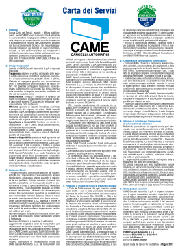
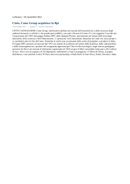
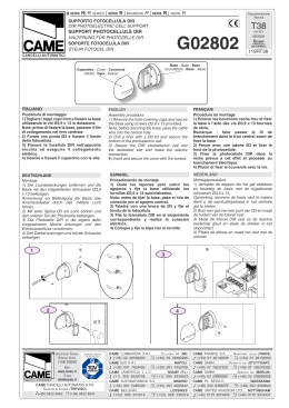
SERIE
Z 24
QUADRO COMANDO
PER MOTORIDUTTORI A 24V
MANUALE D’INSTALLAZIONE
ZL180
Italiano
IT
ITALIANO
“IMPORTANTI ISTRUZIONI DI SICUREZZA PER L’INSTALLAZIONE”
“ATTENZIONE: L’INSTALLAZIONE NON CORRETTA PUÓ CAUSARE GRAVI DANNI, SEGUIRE TUTTE LE ISTRUZIONI DI INSTALLAZIONE”
“IL PRESENTE MANUALE É DESTINATO ESCLUSIVAMENTE A INSTALLATORI PROFESSIONALI O A PERSONE COMPETENTI”
Questo simbolo indica parti da leggere con attenzione.
Questo simbolo indica parti riguardanti la sicurezza.
Questo simbolo indica cosa comunicare all’utente.
2 Destinazione e ambiti d’impiego
2.1 - DESTINAZIONE D’USO
Il quadro comando ZL180 è stato progettato per il comando delle automazioni per cancelli a battente F7024N, A3024N e A5024N.
Ogni installazione e uso difformi da quanto indicato nel seguente manuale sono da considerarsi vietate.
2.2 - AMBITI D’IMPIEGO
Rispettare distanze e diametri dei cavi come indicato nella tabella “tipo cavi e spessore minimi”.
La potenza complessiva dei motori non deve superare i 300W.
3 Riferimenti normativi
Came Cancelli Automatici è un’azienda certificata per il sistema di gestione della qualità aziendale ISO 9001:2000 e di gestione
ambientale ISO 14001. Came progetta e produce interamente in Italia.
Il prodotto in oggetto è conforme alle seguenti normative: vedi paragrafo 13 - Dichiarazione di conformità - pag. 19.
4 Descrizione
Progettata e costruita interamente dalla CAME Cancelli Automatici
S.p.A. Garantita 24 mesi salvo manomissioni.
Il quadro comando va alimentato a 230V a.c., con frequenza max
50/60Hz.
I dispositivi di comando e gli accessori sono a 24V. Attenzione! gli
accessori non devono superare complessivamente i 34W.
La centralina è dotata di un dispositivo amperometrico che
controlla costantemente il valore della spinta del motore.
Quando il cancello incontra un ostacolo, immediatamente il
sensore amperometrico rileva un sovraccarico nella spinta
einterviene nel movimento del cancello invertendone la direzione:
- lo riapre quando si sta chiudendo(1);
- lo richiude quando si sta aprendo.
Appositi trimmers regolano:
- il tempo di intervento della chiusura automatica;
- ritardo chiusura del motoriduttore M2;
- la sensibilità di rilevazione del dispositivo amperometrico,
separatamente per la marcia normale e per il rallenta-mento.
Ulteriori opzioni implementate:
- controllo di un solo motoriduttore;
- riduzione della velocità periferica (per ante oltre i 3 m);
- possibilità di trasformare la funzione del finecorsa di apertura
da Stop a Rallentamento;
- collegamento di una elettroserratura (in alternativa al 2°
canale radio oppure alla lampadina spia “cancello aperto”) con
eventuale aggiunta della funzione “colpo d’ariete”.
(1)
Attenzione: in questo caso, dopo 3 rilevamenti d’ostacolo consecutivi, il
cancello si ferma in apertura e viene esclusa la chiusura automatica; per
riprendere il movimento bisogna premere il pulsante di comando o usare
il radiocomando.
Tutte le connessioni sono protette da fusibili rapidi, vedi tabella.
La scheda eroga e controlla le seguenti funzioni:
- chiusura automatica dopo un comando di apertura;
- prelampeggio dell’indicatore di movimento;
- rilevazione d’ostacolo a cancello fermo in qualsiasi punto;
- verifica continua del funzionamento fotocellule.
Le modalità di comando che è possibile definire sono:
- apertura/chiusura;
- apertura/chiusura ad azione mantenuta;
- apertura parziale;
- stop totale.
Le fotocellule, dopo la rilevazione di un ostacolo, possono
provocare, secondo la modalità di collegamento:
- la riapertura se il cancello sta chiudendo;
- lo stop parziale.
DATI TECNICI
tensione di alimentazione 230V - 50/60Hz
potenza massima ammessa 300W
assorbimento a riposo
potenza massima per accessori a 24V
classe di isolamento dei circuiti
materiale del contenitore
grado di protezione del contenitore
85mA
34W
II
ABS
IP54
temperatura di esercizio -20 / +55°C
TABELLA FUSIBILI
a protezione di:
Motore/i
Scheda elettronica (linea)
Accessori
Dispositivi di comando (centralina)
fusibile da:
6.3A-F
1.6A-F
2A-F
630mA-F
Pag. 2 - Codice manuale: 319U17 ver. 1.1 01/2009 © CAME cancelli automatici s.p.a. - I dati e le informazioni indicate in questo manuale sono da ritenersi suscettibili di modifica in qualsiasi momento e senza obbligo di preavviso da parte di CAME cancelli automatici s.p.a.
1 Legenda simboli
ITALIANO
4.2 - COMPONENTI PRINCIPALI
Grigio
Giallo
Giallo
1
Marrone
Blu
Rosso
1 - Trasformatore
2 - Fusibile della centralina
3 - Trimmers per le varie regolazioni (vedi pag.
9)
4 - Pulsanti per la memorizzazione del codice
radio
5 - Connettore per la scheda di radiofrequenza
per il comando a distanza
6 - Morsettiera per il collegamento dell’antenna
7 - Morsettiere per il collegamento di accessori
e dispositivi di comando
8 - Morsettiere per il collegamento dei
motoriduttori
9 - Morsettiera per l’alimentazione di rete a
230V a.c.
10 - Fusibile di linea
11 - Fusibile del motore M1
12 - Fusibile del motore M2
13 - Fusibile degli accessori
14 - Selettore delle funzioni
15 - Gruppo Led di controllo e di segnalazione
Bianco
Nero
Pag. 3 - Codice manuale: 319U17 ver. 1.1 01/2009 © CAME cancelli automatici s.p.a. - I dati e le informazioni indicate in questo manuale sono da ritenersi suscettibili di modifica in qualsiasi momento e senza obbligo di preavviso da parte di CAME cancelli automatici s.p.a.
4.1 - DIMENSIONI, INTERASSI E FORI DI FISSAGGIO
Arancione
2
Viola
3
4
15
5
14
10
Attenzione! Prima di intervenire
sull’apparecchiatura, togliere la tensione di
linea e scollegare le batterie di emergenza
(se presenti).
9
11
8
12
13
7
6
Prima di procedere all’installazione è necessario:
• Verificare che il punto di fissaggio del quadro elettrico sia in una zona protetta dagli urti, che le superfici di ancoraggio siano solide, e
che il fissaggio venga fatto con elementi idonei (viti, tasselli, ecc) alla superficie.
• Prevedere adeguato dispositivo di disconnesione onnipolare, con distanza maggiore di 3 mm tra i contatti, a sezionamento
dell’alimentazione
•
Verificare che le eventuali connessioni interne al contenitore (eseguite per la continuità del circuito di protezione) siano provviste
di isolamento supplementare rispetto ad altre parti conduttrici interne.
• Predisporre tubazioni e canaline adeguate per il passaggio dei cavi elettrici garantendone la protezione contro il danneggiamento
meccanico.
5.2 - ATTREZZI E MATERIALI
Assicurarsi di avere tutti gli strumenti ed il materiale necessario, per effettuare l’installazione nella massima sicurezza, secondo le
normative vigenti. Ecco alcuni esempi.
5.3 - FISSAGGIO E MONTAGGIO DELLA SCATOLA
5
21
Fissare la base del quadro in una zona protetta; si consiglia di
usare viti di diametro max. 6 mm testa bombata con impronta
a croce.
Forare sui fori presfondati e inserire i pressacavi con i tubi
corrugati per il passaggio dei cavi elettrici.
N.B.: i fori presfondati hanno diametri differenti: 23, 29 e 37 mm.
Assemblare le cerniere a pressione.
!!
Pag. 4 - Codice manuale: 319U17 ver. 1.1 01/2009 © CAME cancelli automatici s.p.a. - I dati e le informazioni indicate in questo manuale sono da ritenersi suscettibili di modifica in qualsiasi momento e senza obbligo di preavviso da parte di CAME cancelli automatici s.p.a.
5.1 - VERIFICHE PRELIMINARI
295
ITALIANO
5 Installazione
Pag. 5 - Codice manuale: 319U17 ver. 1.1 01/2009 © CAME cancelli automatici s.p.a. - I dati e le informazioni indicate in questo manuale sono da ritenersi suscettibili di modifica in qualsiasi momento e senza obbligo di preavviso da parte di CAME cancelli automatici s.p.a.
15 mm~
scorrono per ruotare
Inserire, a scatto, il coperchio sulle cerniere. Chiuderlo e fissarlo con le viti in
dotazione.
Dopo le regolazioni e settaggi, fissare il coperchio con le viti in
dotazione.
6 Collegamenti elettrici
6.1 TIPO CAVI E SPESSORI MINIMI
Lunghezza cavo
1 < 10 m
Lunghezza cavo
10 < 20 m
Lunghezza cavo
20 < 30 m
Alimentazione quadro 230V
3G x 1,5 mm2
3G x 2,5 mm2
3G x 4 mm2
Alimentazione motore 24V
2 x 1 mm2
2 x 1,5 mm2
2 x 2,5 mm2
2 x 0,5 mm2
2 x 1 mm2
2 x 1,5 mm2
2 x 0,5 mm2
2 x 0.5 mm2
2 x 0,5 mm2
4 x 0,5 mm2
4 x 0,5 mm2
4 x 0,5 mm2
Alimentazione accessori
2 x 0,5 mm2
2 x 0,5 mm2
2 x 1 mm2
Dispositivi di comando e di sicurezza
2 x 0,5 mm2
2 x 0,5 mm2
2 x 0,5 mm2
Collegamento
Lampeggiatore
Trasmettitori fotocellule
Ricevitori fotocellule
Collegamento antenna
Tipo cavo
FROR CEI 20-22
CEI EN
50267-2-1
RG58
max. 10 m
N.B. Qualora i cavi abbiano lunghezza diversa rispetto a quanto previsto in tabella, si determini la sezione dei cavi sulla base
dell’effettivo assorbimento dei dispositivi collegati e secondo le prescrizioni indicate dalla normativa CEI EN 60204-1.
Per i collegamenti che prevedano più carichi sulla stessa linea (sequenziali), il dimensionamento a tabella deve essere riconsiderato
sulla base degli assorbimenti e delle distanze effettivi.
Per i collegamenti di prodotti non contemplati in questo manuale fa fede la documentazione allegata ai prodotti stessi.
ITALIANO
Inserire le cerniere nella scatola (sul lato destro
o sinistro a scelta) e fermarle con le viti e le
rondelle in dotazione.
Motoriduttore a 24V (d.c.)
ad azione ritardata in apertura (M1),
installato a sinistra (vista interna)
- impianto standard -
Motoriduttore a 24V (d.c.)
ad azione ritardata in chiusura (M2),
installato a destra (vista interna)
- impianto standard -
RA-RA = Microinterruttore
di stop in apertura
RC-RC = Microinterruttore
di rallentamento in chiusura
motoriduttori FAST
Motoriduttore a 24V (d.c.)
ad azione ritardata in apertura (M1),
installato a sinistra (vista interna)
- impianto standard -
Motoriduttore a 24V (d.c.)
ad azione ritardata in chiusura (M2),
installato a destra (vista interna)
- impianto standard E
EM
AC
KCO
L
KCO
LNU
CK
UNLO
LOCK
M = rosso
N = nero
RA-RA = Microinterruttore
di stop in apertura
RC-RC = Microinterruttore
di rallentamento in chiusura
Pag. 6 - Codice manuale: 319U17 ver. 1.1 01/2009 © CAME cancelli automatici s.p.a. - I dati e le informazioni indicate in questo manuale sono da ritenersi suscettibili di modifica in qualsiasi momento e senza obbligo di preavviso da parte di CAME cancelli automatici s.p.a.
motoriduttori ATI
CAM
ITALIANO
6.2 - COLLEGAMENTO MOTORIDUTTORI
default
CH2 = A3024N
F7024N
a)
b)
c)
Il quadro è predisposto per il controllo di due motoriduttori (cancelli a 2 ante).
Nel caso di un solo motoriduttore (cancelli a 1 anta; motore M2), operare
come segue:
a) - Selezionare i dip 4 e 6 in ON (e i dip 1, 2, 3, 5 in OFF);
b) - premere CH1: il led rosso PROG inizia a lampeggiare;
c) - quando il led rimane acceso (dopo circa 5 s) l’operazione è
terminata;
d) - riportare i dip in OFF (o allo stato precedente, determinato dalla
selezione delle funzioni, vedi par. 7 pag. 12).
d)
CH1 = 1 anta
default
CH2 = 2 ante
N.B.: per tornare alla selezione di default, seguire la stessa procedura
premendo CH2.
a)
b)
c)
d)
ITALIANO
CH1 = A5024N
N.B.: per tornare alla selezione di default, seguire la stessa procedura
premendo CH2.
OPZIONI COLLEGAMENTO MOTORIDUTTORI
Pag. 7 - Codice manuale: 319U17 ver. 1.1 01/2009 © CAME cancelli automatici s.p.a. - I dati e le informazioni indicate in questo manuale sono da ritenersi suscettibili di modifica in qualsiasi momento e senza obbligo di preavviso da parte di CAME cancelli automatici s.p.a.
ZL180 è tarato per il comando dei modelli F7024N o A3024N per ante
fino a 3 metri.
Per comandare i modelli A5024N (oltre 3 m di larghezza anta) e
ridurre la velocità periferica, operare come segue:
a) - Selezionare i dip 1 e 6 in ON (e i dip 2, 3, 4, 5 in OFF);
b) - premere CH1: il led rosso PROG inizia a lampeggiare;
c) - quando il led rimane acceso (dopo circa 5 s) l’operazione è
terminata;
d) - riportare i dip in OFF (o allo stato precedente, determinato
dalla selezione delle funzioni, vedi par. 7 pag. 12).
CH2 = Rallentamento in
apertura
default
CH1 = Stop in
apertura
N.B.: per tornare alla selezione di default, seguire la stessa procedura
premendo CH1.
a)
b)
c)
d)
6.3 - ALIMENTAZIONE ACCESSORI
Morsetti per l’alimentazione degli accessori:
- a 24V a.c. (corrente alternata) normalmente;
- a 24V d.c. (corrente continua) quando intervengono le
batterie d’emergenza;
Potenza complessiva consentita: 34W
Alimentazione 230V (a.c.),
frequenza 50/60 Hz
+
6.4 - DISPOSITIVI DI SEGNALAZIONE E ILLUMINAZIONE
Lampadina spia cancello aperto
(Portata contatto: 24V - 3W max)
- Segnala la posizione del cancello
aperto. Si spegne quando il
cancello è chiuso.
(Vedi anche cap. 6.5)
Lampeggiatore di movimento
(Portata contatto: 24V - 25W max)
- Lampeggia durante le fasi di
apertura e chiusura del cancello.
Pag. 8 - Codice manuale: 319U17 ver. 1.1 01/2009 © CAME cancelli automatici s.p.a. - I dati e le informazioni indicate in questo manuale sono da ritenersi suscettibili di modifica in qualsiasi momento e senza obbligo di preavviso da parte di CAME cancelli automatici s.p.a.
OPZIONI COLLEGAMENTO MOTORIDUTTORI
ITALIANO
I microinterruttori collegati sui morsetti RA, di default determinano lo
stop in apertura.
Se si vuole invece il rallentamento in apertura, operare come segue:
a) - Selezionare i dip 5 e 6 in ON (e i dip 1, 2, 3, 4 in OFF);
b) - premere CH2: il led rosso PROG inizia a lampeggiare;
c) - quando il led rimane acceso (dopo circa 5 s) l’operazione è
terminata;
d) - riportare i dip in OFF (o allo stato precedente, determinato
dalla selezione delle funzioni, vedi par. 7 pag. 12).
ITALIANO
6.5 - SERRATURA ELETTRICA
Pag. 9 - Codice manuale: 319U17 ver. 1.1 01/2009 © CAME cancelli automatici s.p.a. - I dati e le informazioni indicate in questo manuale sono da ritenersi suscettibili di modifica in qualsiasi momento e senza obbligo di preavviso da parte di CAME cancelli automatici s.p.a.
ZL180 consente di collegare, in due modalità alternative, un’elettroserratura a 12V (15W max) e, se necessario, attivare anche la
funzione “colpo d’ariete”.
o
Modo 1 - Esclude l’utilizzo del 2° canale radio su B1-B2; dopo
od
M
averla connessa, operare come segue:
a) - Selezionare il dip 6 in ON (e i dip 1, 2, 3, 4, 5 in OFF);
b) - premere CH1: il led rosso PROG inizia a lampeggiare;
c) - quando il led rimane acceso (dopo circa 5 s) l’operazione
è terminata;
d) - riportare i dip in OFF (o allo stato precedente, determinato
a)
dalla selezione delle funzioni, vedi par. 7 pag. 12).
1
morsetto
RALL1 del
trasformatore
B2
B1
10
N.B.: per tornare alla selezione di default (2° canale radio su B1B2), seguire la stessa procedura premendo CH2.
PROCEDURA COMUNE
b)
c)
o
Modo 2 - Non permette il collegamento di una
lampada spia su 10-5; dopo averla connessa:
a) - Selezionare i dip 2 e 6 in ON (e i dip 1,
3, 4, 5 in OFF);
b), c), d) - continuare con la PROCEDURA
COMUNE sudescritta.
N.B.: per tornare alla selezione di default
(lampada spia su 10-5), seguire la stessa
procedura premendo CH2.
od
2
morsetto
RALL1 del
trasformatore
interporre
un fusibile
da 3.15 A
M
5
a)
In entrambe le modalità, per attivare il “colpo d’ariete”(1):
a) - Selezionare i dip 3 e 6 in ON (e i dip 1, 2, 4, 5 in OFF);
b), c), d) - continuare con la PROCEDURA COMUNE sudescritta.
N.B.: per escludere il colpo d’ariete, seguire la stessa procedura premendo CH2.
(1)
d)
Ad ogni comando di apertura, le ante premono in battuta di chiusura per un secondo,
facilitando l’operazione di sgancio dell’elettroserratura.
a)
Fotocellule DIR
RX
TX
Contatto (N.C.) di «stop parziale»
- Ingresso per dispositivi di sicurezza tipo
fotocellule, bordi sensibili e altri dispositivi
conformi alle normative EN12978. Arresto
delle ante se in movimento con conseguente predisposizione
alla chiusura automatica.
RX
Fotocellule DIR
TX
Contatto (N.C.) di «riapertura durante la chiusura»
- Ingresso per dispositivi di sicurezza tipo fotocellule,
bordi sensibili e altri dispositivi conformi alle normative
EN 12978. In fase di chiusura delle ante, l’apertura del
contatto provoca l’inversione del movimento fino alla
completa apertura.
RX
Contatto (N.C.) di «stop parziale»
./ # .#
TX
./ # .#
RX
Contatto (N.C.) di «riapertura durante la chiusura»
Fotocellule DOC
Fotocellule DOC
TX
Pag. 10 - Codice manuale: 319U17 ver. 1.1 01/2009 © CAME cancelli automatici s.p.a. - I dati e le informazioni indicate in questo manuale sono da ritenersi suscettibili di modifica in qualsiasi momento e senza obbligo di preavviso da parte di CAME cancelli automatici s.p.a.
ITALIANO
6.6 - DISPOSITIVI DI SICUREZZA
ITALIANO
Pulsante di stop (contatto N.C.)
- Pulsante di arresto del cancello con l’esclusione del ciclo di chiusura
automatica, per riprendere il movimento bisogna premere il pulsante di
comando o il tasto del trasmettitore.
.
Selettore a chiave e/o pulsante di apertura parziale (contatto N.O.)
- Apertura del cancello per il passaggio pedonale.
Selettore a chiave e/o pulsante per comandi (contatto N.O.) Comandi per apertura e chiusura del cancello, premendo il
pulsante o girando la chiave del selettore, il cancello inverte il
movimento o si ferma a seconda della selezione effettuata sui
dip-switch (vedi selezioni funzioni, dip 2 e 3).
6.8 - COLLEGAMENTO ELETTRICO PER IL TEST DI FUNZIONALITÀ DELLE FOTOCELLULE
(DIR)
(DOC)
#
.#
./
Pag. 11 - Codice manuale: 319U17 ver. 1.1 01/2009 © CAME cancelli automatici s.p.a. - I dati e le informazioni indicate in questo manuale sono da ritenersi suscettibili di modifica in qualsiasi momento e senza obbligo di preavviso da parte di CAME cancelli automatici s.p.a.
6.7 - DISPOSITIVI DI COMANDO
&53)"),%M!
48 # .#
48
48
A ogni comando di apertura o di chiusura, la scheda verifica
l’efficienza dei dispositivi di sicurezza (fotocellule). Un eventuale
anomalia delle fotocellule viene identificata con il lampeggio del
led (PROG) sul quadro comando, di conseguenza annulla qualsiasi
comando dal trasmettitore radio o dal pulsante.
Collegamento elettrico per il funzionamento del test di sicurezza delle fotocellule:
- il trasmettitore e il ricevitore, devono essere collegati come da disegno;
- selezionare il dip 9 in ON per attivare il funzionamento del test.
IMPORTANTE:
Quando si attiva la funzione test di sicurezza, i contatti N.C. - se non utilizzati - vanno esclusi sui relativi DIP (vedi capitolo 7 “selezione
funzioni”).
ITALIANO
7 Selezioni funzioni
DIP-SWITCH
ON
OFF
/.
1 ON -
Chiusura automatica - Il temporizzatore della chiusura automatica si attiva a finecorsa in apertura. Il tempo prefissato è
regolabile, ed è comunque condizionato dall’eventuale intervento dei dispositivi di sicurezza e non si attiva dopo uno «stop»
totale di sicurezza o in mancanza di energia elettrica.
2 ON -
Funzione di "apre-stop-chiude-stop" con pulsante (2-7) e trasmettitore radio (con scheda radiofrequenza inse rita).
2 OFF -
Funzione di "apre-chiude" con pulsante (2-7) e trasmettitore radio (con scheda radiofrequenza inserita).
3 ON -
Funzione di "solo apre" con pulsante (2-7) e trasmettitore radio (con scheda radiofrequenza inserita).
4 ON -
Prelampeggio in apertura e in chiusura - Dopo un comando di apertura o di chiusura, il lampeggiatore collegato su 10-E,
lampeggia per 5 secondi prima di iniziare la manovra.
5 ON -
Rilevazione di presenza ostacolo - A motore fermo (cancello chiuso, aperto o dopo un comando di stop totale), impedisce
qualsiasi movimento se i dispositivi di sicurezza (es. fotocellule) rilevano un ostacolo.
6 ON -
Azione mantenuta - Funzionamento del cancello mantenendo premuto il pulsante, pulsante (2-3P) per l’apertura, pulsante
(2-7) per la chiusura.
7 OFF -
Riapertura in fase di chiusura - Le fotocellule, rilevando un ostacolo durante la fase di chiusura dell’anta, provocano
l’inversione di marcia fino alla completa apertura; inserire dispositivo di sicurezza sul morsetto (2-C1); se non utilizzato,
selezionare il dip in ON.
8 OFF -
Stop parziale - Arresto del cancello se in movimento con conseguente predisposizione alla chiusura automatica, inserire
dispositivo di sicurezza sul morsetto (2-C3); se non utilizzato, selezionare il dip in ON.
9 ON -
Funzionamento del test di sicurezza delle fotocellule - Consente alla centralina di verificare l’efficenza dei dispositivi di
sicurezza (fotocellule) dopo ogni comando di apertura o di chiusura;
10 ON -
Tempo di reazione - Aumenta il tempo di attivazione dell’inversione di marcia, comandata dal sensore amperometrico, a 2”.
NB - i dip da 1 a 6 sono usati, in modo indipendente, anche per le opzioni di collegamento motoriduttori e della elettroserratura (pagine 7-8-9).
8 Regolazione trimmer
- «SPEED SENS.»
Regola la sensibilità del dispositivo amperometrico durante la corsa normale.
- «SLOW.SENS.»
Regola la sensibilità del dispositivo amperometrico durante la corsa in rallenramento.
- «DELAY 2M»
Regola il tempo di attesa del secondo motore a ogni manovra di chiusura. Può essere regolato da 1 a 17
secondi.
- «AUTOM. CLOSING» Regola il tempo di attesa in posizione di apertura. Trascorso questo tempo, viene effettuata automaticamente
una manovra di chiusura. Il tempo di attesa può essere regolato da 1 secondo a 150 secondi.
Pag. 12 - Codice manuale: 319U17 ver. 1.1 01/2009 © CAME cancelli automatici s.p.a. - I dati e le informazioni indicate in questo manuale sono da ritenersi suscettibili di modifica in qualsiasi momento e senza obbligo di preavviso da parte di CAME cancelli automatici s.p.a.
Settaggio di default
ITALIANO
9 Regolazione dei finecorsa
Pag. 13 - Codice manuale: 319U17 ver. 1.1 01/2009 © CAME cancelli automatici s.p.a. - I dati e le informazioni indicate in questo manuale sono da ritenersi suscettibili di modifica in qualsiasi momento e senza obbligo di preavviso da parte di CAME cancelli automatici s.p.a.
motoriduttori ATI
Regolazioni da eseguire con
motoriduttori sbloccati: inserire
la chiave di sblocco e ruotarla
in senso orario.
Slitta azionamento
microinterruttori
Viti di fissaggio e
blocco/sblocco dei finecorsa
CA
ME
Finecorsa di chiusura
Finecorsa di apertura
9.1 - FINECORSA DI APERTURA - ATI
A seconda della funzione assegnata al finecorsa di apertura (vedi paragrafo 6.2 pag. 8), le modalità di regolazione sono le seguenti:
Stop in apertura
(funzione di default)
Rallentamento
in apertura
(opzione)
Se interviene provocando lo Stop,
- portare manualmente l’anta in posizione
di massima apertura;
- sbloccare o staccare il finecorsa
e farlo scorrere o riposizionarlo
fino all’attivazione
dell’interuttore come
indicato in figura;
- bloccare il gruppo in questa
posizione.
Se invece interviene attivando il Rallentamento,
- portare manualmente l’anta in posizione di
massima apertura;
- sbloccare o staccare il finecorsa e
farlo scorrere o riposizionarlo
con l’interruttore adiacente
alla slitta come indicato in
figura;
- bloccare il gruppo in questa
posizione.
Interruttore
Interruttore
9.2 - FINECORSA DI CHIUSURA - ATI
Il finecorsa di chiusura attiva solo il rallentamento.
Rallentamento
in chiusura
Per regolare il microinterruttore,
- portare manualmente l’anta in posizione
di chiusura;
- sbloccare o staccare il finecorsa
e farlo scorrere o riposizionarlo
con l’interruttore adiacente
alla slitta come indicato in
figura;
- bloccare il gruppo in questa
posizione.
Interruttore
ATTENZIONE! controllare di aver scambiato il collegamento M-N per il MOTORE DI DESTRA, come indicato a pag. 6.
Regolazioni da eseguire con
motoriduttori sbloccati: inserire
la manopola di sblocco e
ruotarla in senso antiorario.
Camma superiore
Vite di fissaggio e
blocco/sblocco della
camma inferiore
Microinterruttore
di chiusura (sopra)
GRUPPO FINECORSA
Viti di fissaggio e
blocco/sblocco della
camma superiore
Camma inferiore
Microinterruttore
di apertura (sotto)
9.3 - FINECORSA DI APERTURA - FAST
A seconda della funzione assegnata al finecorsa di apertura (vedi paragrafo 6.2 pag. 8), le modalità di regolazione sono le seguenti:
Stop in apertura
(funzione di default)
Se interviene provocando lo Stop,
- portare manualmente l’anta in posizione di massima apertura;
- sbloccare la camma inferiore e ruotarla in senso antiorario fino
all’attivazione dell’interuttore come indicato nella figura;
- bloccare la camma in questa posizione.
Microinterruttore
Interruttore
Camma inferiore
Vite di blocco/sblocco
della camma inferiore
Rallentamento
in apertura
(opzione)
Se invece interviene attivando il Rallentamento,
- portare manualmente l’anta in posizione di massima apertura;
- sbloccare la camma inferiore e ruotarla in senso antiorario fino al
rilascio dell’interruttore come indicato nella figura ;
- bloccare la camma in questa posizione.
Interruttore
Pag. 14 - Codice manuale: 319U17 ver. 1.1 01/2009 © CAME cancelli automatici s.p.a. - I dati e le informazioni indicate in questo manuale sono da ritenersi suscettibili di modifica in qualsiasi momento e senza obbligo di preavviso da parte di CAME cancelli automatici s.p.a.
ITALIANO
motoriduttori FAST
Pag. 15 - Codice manuale: 319U17 ver. 1.1 01/2009 © CAME cancelli automatici s.p.a. - I dati e le informazioni indicate in questo manuale sono da ritenersi suscettibili di modifica in qualsiasi momento e senza obbligo di preavviso da parte di CAME cancelli automatici s.p.a.
Il finecorsa di chiusura attiva solo il rallentamento ed è predisposto PER CANCELLI CON ANTE DA 1.20 FINO A 2.30 M DI LARGHEZZA.
ATTENZIONE! questa regolazione va fatta sempre dopo aver regolato il finecorsa di apertura.
Rallentamento
in chiusura
L = 1.20 < 2.30 m
Per regolare il microinterruttore,
- portare manualmente l’anta in posizione di chiusura;
- sbloccare la camma superiore e ruotarla in senso orario fino al rilascio
dell’interruttore come indicato nella figura;
- bloccare la camma in questa posizione.
Microinterruttore
Interruttore
Camma superiore
Viti di blocco/sblocco
della camma superiore
Se invece l'anta MISURA MENO DI 1.20 METRI, prima di procedere bisogna:
- togliere le 2 viti di fissaggio della
camma superiore;
- estrarre la camma e rimetterla
nella stessa posizione capovolta
(le dimensioni della sagoma per
l'attivazione dell'interruttore
cambiano).
Rallentamento
in chiusura
L = < 1.20
Viti di fissaggio della
camma superiore
Camma superiore
Quindi, per regolare il microinterruttore,
- portare manualmente l’anta in posizione di chiusura;
- sbloccare la camma superiore e ruotarla in senso orario fino al rilascio
dell’interruttore come indicato nella figura;
- bloccare la camma in questa posizione.
Interruttore
ITALIANO
9.4 - FINECORSA DI CHIUSURA - FAST
ELENCO DI SEGNALAZIONE DEI LED DI CONTROLLO DEI DISPOSITIVI DI COMANDO E SICUREZZA:
- «ALIM»
Led di colore verde. Normalmente acceso.
Segnala la corretta alimentazione della scheda;
- «PROG» Led di colore rosso. Normalmente spento.
Durante la procedura di attivazione del trasmettitore, si accende o lampeggia. Lampeggia più velocemente in
combinazione con i led C1/C3/ST;
- «C1»
Led di colore giallo. Normalmente spento.
Accesso e con led PROG lampeggiante, segnala la presenza di oggetti tra le fotocellule (collegate in funzione di
RIAPERTURA DURANTE LA CHIUSURA) oppure il loro mancato funzionamento;
- «C3»
Led di colore giallo. Normalmente spento.
Accesso e con led PROG lampeggiante, segnala la presenza di oggetti tra le fotocellule (collegate in funzione di STOP
PARZIALE) oppure il loro mancato funzionamento;
- «ST»
Led di colore giallo. Normalmente spento.
Accesso e con led PROG lampeggiante, segnala l’azionamento del pulsante di STOP TOTALE oppure il suo mancato
funzionamento.
11 Attivazione del comando radio
11.1 - ANTENNA
Collegare il cavo RG58 dell’antenna agli
appositi morsetti.
Eventuale uscita del secondo canale del
ricevitore radio (contatto N.O.).
Portata contatto: 5A-24V (d.c.).
(Vedi anche cap. 6.5)
11.2 - SCHEDA DI RADIOFREQUENZA
Innestare la scheda di radiofrequenza sulla scheda elettronica DOPO
AVER TOLTO LA TENSIONE (o scollegato le batterie).
N.B.: La scheda elettronica riconosce la scheda di radiofrequenza
solo quando viene alimentata.
Scheda AF
Pag. 16 - Codice manuale: 319U17 ver. 1.1 01/2009 © CAME cancelli automatici s.p.a. - I dati e le informazioni indicate in questo manuale sono da ritenersi suscettibili di modifica in qualsiasi momento e senza obbligo di preavviso da parte di CAME cancelli automatici s.p.a.
ITALIANO
10 Led di segnalazione
ITALIANO
11.3 - TRASMETTITORI
AME
vedi foglio istruzioni inserito nella confezione
della scheda di radiofrequenza AF43SR
C
E
CAM
E
CAM
TOUCH
TOP
TCH 4024 • TCH 4048
TOP-432NA • TOP-434NA
TOP-432S
TOP
TOP-432A • TOP-434A
TOP-302A • TOP-304A
zio
ni
su
co
nf
ez
ion
e
TOP
E
ru
CAM
CAM
ist
E
E
CAM
di
CAM
E
ve
Pag. 17 - Codice manuale: 319U17 ver. 1.1 01/2009 © CAME cancelli automatici s.p.a. - I dati e le informazioni indicate in questo manuale sono da ritenersi suscettibili di modifica in qualsiasi momento e senza obbligo di preavviso da parte di CAME cancelli automatici s.p.a.
ATOMO
AT01 • AT02
AT04
TAM
TFM
T432 • T434 • T438
TAM-432SA
T132 • T134 • T138
T152 • T154 • T158
E
CAM
E
CAM
E
CAM
E
CAM
E
CAM
E
CAM
E
CAM
E
CAM
CAM
TWIN
TWIN2 • TWIN4
E
CH1 = Canale per comandi diretti a una funzione della scheda del motoriduttore (comando “solo apre” / “apre-chiude-inversione”
oppure “apre-stop-chiude-stop”, a seconda della selezione effettuata sui dip-switch 2 e 3).
CH2 = Canale per comando diretto a un dispositivo accessorio collegato su B1-B2.
1) Tenere premuto il tasto “CH1” sulla scheda elettronica. Il led lampeggia.
CH1
LED intermittente
2) Premere il tasto del trasmettitore da memorizzare. Il led rimarrà acceso a segnalare l’avvenuta memorizzazione.
LED acceso
T1
3) Ripetere la procedura del punto 1 e 2 per il tasto “CH2” associandolo con un altro tasto del trasmettitore.
CH2
T2
Pag. 18 - Codice manuale: 319U17 ver. 1.1 01/2009 © CAME cancelli automatici s.p.a. - I dati e le informazioni indicate in questo manuale sono da ritenersi suscettibili di modifica in qualsiasi momento e senza obbligo di preavviso da parte di CAME cancelli automatici s.p.a.
ITALIANO
11.4 - MEMORIZZAZIONE
Pag. 19 - Codice manuale: 319U17 ver. 1.1 01/2009 © CAME cancelli automatici s.p.a. - I dati e le informazioni indicate in questo manuale sono da ritenersi suscettibili di modifica in qualsiasi momento e senza obbligo di preavviso da parte di CAME cancelli automatici s.p.a.
I nostri prodotti sono realizzati con materiali diversi. La maggior parte di essi (alluminio, plastica, ferro, cavi elettrici) è assimilabile
ai rifiuti solidi e urbani. Possono essere riciclati attraverso la raccolta e lo smaltimento differenziato nei centri autorizzati.
Altri componenti (schede elettroniche, batterie dei radiocomandi etc.) possono invece contenere sostanze inquinanti. Vanno quindi
rimossi e consegnati a ditte autorizzate al recupero e allo smaltimento degli stessi.
13 Dichiarazione di conformità
DICHIARAZIONE DEL FABBRICANTE
Ai sensi dell’allegato II B della Direttiva Macchine 98/37/CE
CAME Cancelli Automatici S.p.A.
via Martiri della Libertà, 15
31030 Dosson di Casier - Treviso - ITALY
tel (+39) 0422 4940 - fax (+39) 0422 4941
internet: www.came.it - e-mail: [email protected]
Dichiara sotto la propria responsabilità, che i seguenti prodotti per l’automazione di cancelli e porte da garage,
così denominati:
ZL180
--- NORMATIVE --EN 13241-1
EN 12453
EN 12445
EN 12635
EN 12978
EN 60335-1
EN 61000-6-2
EN 61000-6-3
AVVERTENZA IMPORTANTE!
È vietato mettere in servizio il/i prodotto/i, oggetto della presente
dichiarazione, prima del completamento e/o incorporamento, in
totale conformità alle disposizioni della Direttiva Macchine 98/37/CE
… sono conformi ai requisiti essenziali ed alle disposizioni pertinenti, stabilite dalle seguenti Direttive e alle
parti applicabili delle Normative di riferimento in seguito elencate.
--- DIRETTIVE --98/37/CE - 98/79/CE
98/336/CEE - 92/31/CEE
73/23/CEE - 93/68/CE
89/106/CEE
DIRETTIVA MACCHINE
DIRETTIVA COMPATIBILITÀ ELETTROMAGNETICA
DIRETTIVA BASSA TENSIONE
DIRETTIVA MATERIALI DA COSTRUZIONE
Codice di riferimento per richiedere una copia conforme all’originale: DDF B IT A001D
AMMINISTRATORE DELEGATO
Sig. Andrea Menuzzo
ITALIANO
12 Dismissione e smaltimento
www.came.com
www.came.it
08_2009
I dati e le informazioni indicate in questo manuale sono da ritenersi suscettibili di modifica in qualsiasi momento e senza obbligo di preavviso da parte di CAME Cancelli Automatici S.p.a.
Italiano - Codice manuale: 319U17 ver. 1.1 01/2009 © CAME cancelli automatici s.p.a.
CAME France S.a.
7, Rue Des Haras
Z.i. Des Hautes Patures
92737 Nanterre Cedex - FRANCE
(+33) 1 46 13 05 05
(+33) 1 46 13 05 00
CAME Automatismes S.a.
3, Rue Odette Jasse
13015 Marseille - FRANCE
(+33) 4 95 06 33 70
(+33) 4 91 60 69 05
CAME Automatismos S.a.
C/juan De Mariana, N. 17-local
28045 Madrid - SPAIN
(+34) 91 52 85 009
(+34) 91 46 85 442
CAME United Kingdom Ltd.
Unit 3 Orchard Business Park
Town Street, Sandiacre
Nottingham - Ng10 5du - GREAT BRITAIN
(+44) 115 9210430
(+44) 115 9210431
CAME Group Benelux S.a.
Zoning Ouest 7
7860 Lessines - BELGIUM
(+32) 68 333014
(+32) 68 338019
CAME Gmbh Seefeld
Akazienstrasse, 9
16356 Seefeld
Bei Berlin - GERMANY
(+49) 33 3988390
(+49) 33 39883985
CAME Cancelli Automatici S.p.a.
Via Martiri Della Libertà, 15
31030 Dosson Di Casier (Tv)
(+39) 0422 4940
(+39) 0422 4941
Informazioni Commerciali 800 848095
CAME Service Italia S.r.l.
Via Della Pace, 28
31030 Dosson Di Casier (Tv)
(+39) 0422 383532
(+39) 0422 490044
Assistenza Tecnica 800 295830
CAME Gmbh
Kornwestheimer Str. 37
70825 Korntal
Munchingen Bei Stuttgart - GERMANY
(+49) 71 5037830
(+49) 71 50378383
CAME Americas Automation Llc
11405 NW 122nd St.
Medley
Medley, FL 33178 - U.S.A
(+1) 305 433 3307
(+1) 305 396 3331
CAME Gulf Fze
Office No: S10122a2o210
P.O. Box 262853
Jebel Ali Free Zone - Dubai - U.A.E.
(+971) 4 8860046
(+971) 4 8860048
CAME Russia
Ul. Otradnaya D. 2b, Str. 2
127273, Moscow - RUSSIA
(+7) 495 739 00 69
(+7) 495 739 00 69 (ext. 226)
CAME (Shanghai) Automatic Gates Co. Ltd.
1st Floor, Building 2,
No. 1755, South Hongmei Road
Shanghai 200237 - CHINA
(+86) 021 61255005
(+86) 021 61255007
CAME Portugal
Ucj Portugal Unipessoal Lda
Rua Jùlio Dinis, N. 825
2esq, 4050 327 Porto – PORTUGAL
(+351) 915 371 396
CAME Sud s.r.l.
Via F. Imparato, 198
Centro Mercato 2, Lotto A/7
80146 Napoli
(+39) 081 7524455
(+39) 081 7529190
Z 24
SERIES
CONTROL PANEL
FOR 24V OPERATORS
INSTALLATION MANUAL
ZL180
English
EN
“IMPORTANT INSTALLATION, SAFETY INSTRUCTIONS”
“CAUTION: IMPROPER INSTALLATION MAY CAUSE SERIOUS DAMAGE, FOLLOW ALL INSTALLATION INSTRUCTIONS CAREFULLY”
“THIS MANUAL IS ONLY FOR PROFESSIONAL INSTALLERS OR QUALIFIED PERSONS”
1 Legend of symbols
2 Intended use and application
2.1 - INTENDED USE
The ZL180 control panel is designed to control the F7024N, A3024N and A5024N swing gate operators.
The use of this product for purposes other than as described above and installation executed in a manner other than
as instructed in this technical manual are prohibited.
2.2 - APPLICATION
Make sure you respect the distances and cable diameters as shown in “cable types and minimal thicknesses” table.
The overall power of the motors must not exceed 300W.
3 Reference Standards
For its quality processes management Came Cancelli Automatici is ISO 9001:2000 certified, and for its environmental management it is
ISO 14001 certified. Came designs and manufactures entirely in Italy.
This product complies with the following standards: see chapter 13 - Conformity declaration - pag. 19.
4 Description
This product is engineered and manufactured by CAME cancelli
automatici s.p.a. and complies with current safety regulations.
Guaranteed 24 months if not tampered with.
The control panel works on 230V a.c. of power, through the
terminals L-N, 50/60Hz frequency.
Both command and control devices and accessories are 24V
powered. Warning! Accessories must not exceed 34 W overall.
The control unit is fitted with an amperometric device which
constantly regulates the motor’s drive coefficient.
When the gate runs into an obstacle, the amperometric sensor
immediately detects an overcharge in the drive and redirects the
gate’s direction of movement,
and:
(1)
- opens it if it is closing ;
- closes it if it is opening.
- the automatic closing run time;
- the second gate leaf’s motion time difference;
- the amperometric device’s detection sensitivity, in separately
in terms of normal opening and closing and braking.
Further implemented options:
- controlling of just one gearmotor;
- peripheral speed reduction (for gate leaves of over 3 m);
- option to change opening endpoint fromt Stop to
Deceleration;
- connecting up an electric lock (alternatively to the 2nd
radio channel or the “Open Gate” indicator light) and possibly
adding the “Ram Blow” function.
TECHNICAL FEATURES
(1)
Warning!: in this case, after 3 consecutive obstacle detections, the gate
will stop open excluding the automatic closing function; for movement to
start again press the command button or use the remote control.
All connections are protected by quick fuses, see table.
The card provides and controls the following functions:
- automatic closing after an open-command;
- pre-flashing by the motion indicator;
- obstacle detection when gate is still in any position;
- continual monitoring of photocell operation.
The following command modes are possible:
- open/close;
- open/close and maintained action;
- partially open;
- complete stop.
After detecting an obstacle and depending on the type of
connection used, the photocells may cause:
- reopening of the gate when it is closing;
- partial stop.
Apposite trimmers regulate:
Power supply 230V - 50/60Hz
max. rated power 300W
Power draw when idling
Max power of 24V accessories
Insulation rating
Material
Protection rating
85mA
34W
II
ABS
IP54
operating temperature -20 / +55°C
FUSES
protection fuse type
Motor/s 6.3A-F
Electronic board (power supply line) 1.6A-F
Accessories 2A-F
Control devices 630mA-F
Pag. 2 - Manual code: 319U17 ver. 1.1 01/2009 © CAME cancelli automatici s.p.a. - The data and information reported in this installation manual are susceptible to change at any time and without obligation on CAME cancelli automatici s.p.a. to notify users.
ENGLISH
This symbol indicates sections to be read with particular care.
This symbol indicates sections concerning safety
This symbol indicates notes to communicate to users.
ENGLISH
4.2 - MAIN COMPONENTS
1
2
3
4
5
6
7
Grey
Yellow
Yellow
1
Brown
Blue
Red
- Transformer
- Control unit fuse
- Trimmers (see page 9)
- Buttons for memorising the radio code
- Plug for the remote control frequency card
- Terminal board for connecting the antenna
- Terminal board for connecting accessories
and control devices
8 - Terminal board for connecting the
gearmotors
9 - Terminal board for 230V a.c. power grid
10 - Line fuse
11 - M1 motor fuse
12 - M2 motor fuse
13 - Accessories fuse
14 - Fucntions selector
15 - Control and signalling LED unit
White
Black
Pag. 3 - Manual code: 319U17 ver. 1.1 01/2009 © CAME cancelli automatici s.p.a. - The data and information reported in this installation manual are susceptible to change at any time and without obligation on CAME cancelli automatici s.p.a. to notify users.
4.1 - DIMENSIONS, SPANS AND ANCHORING HOLES
Orange
Violet
2
3
4
15
5
14
10
Warning! Before acting on the machinery,
cut off the main power supply and
disconnect any emergency batteries.
9
11
8
12
13
7
6
5 Installation
5.2 - TOOLS AND MATERIALS
Make sure you have all the tools and materials you will need for the installation at hand to work in total safety and compliance with the
current standards and regulations. The following figure illustrates the minimum equipment needed by the installer.
Here are some examples.
5.3 - FIXING AND MOUNTING THE BOX
5
21
Fix the base of the panel in a protected area; we suggest
using round top Phillips recessed head screws of max. 6mm in
diameter.
Perforate the pre-punched holes and insert the cable glands with
the corrugated tubing for the electrical cables to travel through
N.B.: the pre-punched holes have the following diameters:
23m 29 and 37 mm.
Assemble the pressure hinges.
!!
Pag. 4 - Manual code: 319U17 ver. 1.1 01/2009 © CAME cancelli automatici s.p.a. - The data and information reported in this installation manual are susceptible to change at any time and without obligation on CAME cancelli automatici s.p.a. to notify users.
Before installing do the following:
• Check that the panel’s anchoring point is protected from possible blows, and that the anchoring surface is solid. Also check that the
anchoring is done using the appropriate bolts, screws etc.
• Make sure you have a suitable omnipolar cut-off device with contacts more than 3 mm apart, and independent (sectioned off) power
supply.
•
Make sure that any connections inside the case (that provide continuance to the protective circuit) are fitted with extra insulation
as compared to the other conductive parts inside;
• Make sure you have suitable tubing and conduits for the electrical cables to pass through and be protected against mechanical
damage.
295
ENGLISH
5.1 - PRELIMINARY CHECKS
Insert the pressure hinges into the box (on the
left or right as you wish) and set them using the
provided screws and washers.
Pag. 5 - Manual code: 319U17 ver. 1.1 01/2009 © CAME cancelli automatici s.p.a. - The data and information reported in this installation manual are susceptible to change at any time and without obligation on CAME cancelli automatici s.p.a. to notify users.
They must slide in order to turn
Snap the cover into place onto the hinges. Close it and fix it using the
provided screws.
After the adjustments and settings, fix the cover using the provided
screws.
6 Electrical connections
6.1 - CABLE LIST AND MINIMUM THICKNESSES
Length of cable
1 < 10 m
Length of cable
10 < 20 m
Length of cable
20 < 30 m
3G x 1,5 mm2
3G x 2,5 mm2
3G x 4 mm2
2 x 1 mm2
2 x 1,5 mm2
2 x 2,5 mm2
2 x 0,5 mm2
2 x 1 mm2
2 x 1,5 mm2
2 x 0,5 mm2
2 x 0.5 mm2
2 x 0,5 mm2
4 x 0,5 mm2
4 x 0,5 mm2
4 x 0,5 mm2
Power supply to accessories
2 x 0,5 mm2
2 x 0,5 mm2
2 x 1 mm2
Control and safety devices
2 x 0,5 mm2
2 x 0,5 mm2
2 x 0,5 mm2
Connections
Type
of cable
Control panel power supply 230V
Motor power supply 24V
flashing lamp
Transmitter photocells
Receiver photocells
Antenna connection
FROR CEI
20-22
CEI EN
50267-2-1
RG58
max. 10 m
N.B.: If the cable length differs from that specified in the table, then you must determine the proper cable diameter based on the actual
power draw from the connected devices and according to the CEI EN 60204-1 standards.
For connections that require several, sequential loads, the sizes given on the table must be re-evaluated based on actual power draw
and distances.
When connecting products that are not specified in this manual, please follow the documentation provided with said products.
ENGLISH
15 mm~
6.2 - CONNECTING TO THE GEARMOTORS
ATI gearmotors
RA-RA = Opening-speed blocker
microswitch
RC-RC = Closing-speed reduction
microswitch
FAST gearmotors
24V d.c. gearmotor
featuring delayed action on opening (M1),
Left-hand installed (inside view)
- Standard installation -
24V d.c. gearmotor
featuring delayed action on closing (M2),
Left-hand installed (inside view)
- Standard installation -
AC
CAM
E
EM
KCO
L
KCO
LNU
CK
UNLO
LOCK
M = red
N = black
RA-RA = Opening-speed blocker
microswitch
RC-RC = Closing-speed reduction
microswitch
Pag. 6 - Manual code: 319U17 ver. 1.1 01/2009 © CAME cancelli automatici s.p.a. - The data and information reported in this installation manual are susceptible to change at any time and without obligation on CAME cancelli automatici s.p.a. to notify users.
24V d.c. gearmotor
featuring delayed action on closing (M2),
Left-hand installed (inside view)
- Standard installation -
ENGLISH
24V d.c. gearmotor
featuring delayed action on opening (M1),
Left-hand installed (inside view)
- Standard installation -
ENGLISH
default
CH2 = A3024N
F7024N
N.B.: to return to default, follow the same procedure while pressing CH2.
a)
GEARMOTORS CONNECTION OPTIONS
Pag. 7 - Manual code: 319U17 ver. 1.1 01/2009 © CAME cancelli automatici s.p.a. - The data and information reported in this installation manual are susceptible to change at any time and without obligation on CAME cancelli automatici s.p.a. to notify users.
The ZL180 is calibrated to the F7024N or A3024N commands for gate
CH1 = A5024N
leaves of up to 3 meters.
To command A5024N models (with gate leaves of over 3 m ) and reduce
peripheral speed, do the following:
a) - Set dip switches 1 and 6 to ON (and dip switches 2, 3, 4, 5 to
OFF);
b) - press CH1: the red PROG led will start to blink;
c) - when the led stays on (after about 5 seconds) the procedure is
complete;
d) - set to the dip switches back to OFF (or to the previous position,
which depends on the functions selection, see paragraph 7, page 12).
b)
c)
The control panel is set for 2 gearmotors (2 leaved gates).
CH1 = 1 gate leaf
he following:
With only one gearmotor (one-leaved gates; M2 gearmotor), do the
a) - Set dip switches 4 and 6 to ON (and dip switches 1, 2, 3, 5 to OFF);;
b) - press CH1: the red PROG led will start to blink;
c) - when the led stays on (after about 5 seconds) the procedure is
complete;
d) - set to the dip switches back to OFF (or to the previous position,
which depends on the functions selection, see paragraph 7, page 12).
d)
default
CH2 = 2 gate leaves
N.B.: to return to default, follow the same procedure while pressing CH2.
a)
b)
c)
d)
CH2 = Opening
slowdown
default
CH1 = Opening
stop
N.B.: to return to default, follow the same procedure while pressing
CH1.
a)
b)
c)
d)
6.3 - POWER SUPPLY TO ACCESSORIES
Terminals for powering the following accessories:
- 24V a.c. (normally alternated power)
- 24V a.c. (continuous power) when the emergency batteries
are in operation.
Overall power allowed: 34W
Power supply
230V (a.c.) 50/60 Hz
+
6.4 - SIGNALLING AND LIGHTING DEVICES
Open gate indicator-light
(socket rating: 24V - 3W max.).
- Turns on when the gate is ajar
or open. It turns off when the gate
is closed.
(Also see Chapt. 6.5)
Signal Flasher
(socket rating: 24V - 25W max.)
- Flashes during opening and
closing phases
Pag. 8 - Manual code: 319U17 ver. 1.1 01/2009 © CAME cancelli automatici s.p.a. - The data and information reported in this installation manual are susceptible to change at any time and without obligation on CAME cancelli automatici s.p.a. to notify users.
GEARMOTORS CONNECTION OPTIONS
ENGLISH
The microswitches on RA terminals, set the opening stop by default.
However, to activate the opening slowdown, do the following:
a) - Set dip switches 5 and 6 to ON (and dip switches 1, 2, 3, 4
to OFF);;
b) - press CH2: the red PROG led will start to blink;
c) - when the led stays on (after about 5 seconds) the procedure
is complete;
d) - set to the dip switches back to OFF (or to the previous
position, which depends on the functions selection, see
paragraph 7, page 12).
6.5 - ELECTRICAL LOCK
Mode 1 – Excludes use of the 2nd radio channel on B1-B2; after
connecting it, operate as follows:
a) - Set dip switch 6 to ON (and dip switches 1, 2, 3, 4, 5
to OFF);;
b) - press CH1: the red PROG led will start to blink;
c) - when the led stays on (after about 5 seconds) the
procedure is complete;
d) - set to the dip switches back to OFF (or to the previous
position, which depends on the functions selection, see
paragraph 7, page 12).
e
od
1
RALL1
transformer
terminal
M
B2
B1
10
a)
N.B.: to return to default (2nd radio channel on B1-B2), follow
the same procedure while pressing CH2.
COMMON PROCEDURE
c)
b)
e
od
Mode 2 - Does not allow connection of an
indicator lamp on 10-5; after connection it:
a) - Set dip switches 2 and 6 to ON (and
dip switches 1, 3, 4, 5 to OFF);;
b), c), d) - continue with the above COMMON
PROCEDURE.
PROCEDUR
N.B.: to return to default (indicator lamp on 10-5),
follow the same procedure while pressing CH2.
2
M
RALL1
transformer
terminal
place
a 3.15 A
fuse in between
5
a)
In both modes, to activate the “ram blow” (1):
a) - Set dip switches 3 and 6 to ON (and dip switches 1, 2, 4, 5 to OFF);;
b), c), d) - continue with the above COMMON PROCEDUR
PROCEDURE.
N.B.: to exclude the ram blow, follow the same procedure while pressing CH2.
(1)
d)
Upon each opening command, the gate leaves press on the closing jamb for one second,
assisting the electrolock release operation.
a)
ENGLISH
Pag. 9 - Manual code: 319U17 ver. 1.1 01/2009 © CAME cancelli automatici s.p.a. - The data and information reported in this installation manual are susceptible to change at any time and without obligation on CAME cancelli automatici s.p.a. to notify users.
ZL180 lets you connect, in two different modes, a 12V (15W max) electrolock and, if necessary, also activate the “Ram Blow” function.
6.6 - SAFETY DEVICES
DIR photocells
TX
“Partial stop” (N.C.) socket
- input for safety devices such as photocells, sensitive
edges and other EN 12978-compliant devices. Halts
moving gate leaves and causes them to automatically
close
RX
DIR photocells
TX
“Open during closing” (N.C.) socket
- Input for safety devices such as photocells, sensitive
edges and other EN 12978 compliant devices. When gate
leaves are closing, opening the contact causes reversal
until total opening is obtained.
RX
“Partial Stop” (N.C.) socket
./ # .#
TX
./ # .#
RX
“Open during closing” (N.C.) socket
DOC photocells
DOC photocells
TX
Pag. 10 - Manual code: 319U17 ver. 1.1 01/2009 © CAME cancelli automatici s.p.a. - The data and information reported in this installation manual are susceptible to change at any time and without obligation on CAME cancelli automatici s.p.a. to notify users.
ENGLISH
RX
6.7 - COMMAND DEVICES
ENGLISH
Key selector and/or partial opening button (N.O. socket)
- Opening of one gate leaf to allow pedestrian passage.
Key selector and/or commands button (N.O. socket)
- Gate closing and opening contacts, by pressing the button or
turning the selector key, the gate movement is inverted or halted
depending on which selection was just made. (see selecting
functions, dips 2 and 3).
6.8 - ELECTRICAL CONNECTION FOR THE PHOTOCELLS FUNCTIONS TEST
(DIR)
(DOC)
#
.#
./
Pag. 11 - Manual code: 319U17 ver. 1.1 01/2009 © CAME cancelli automatici s.p.a. - The data and information reported in this installation manual are susceptible to change at any time and without obligation on CAME cancelli automatici s.p.a. to notify users.
Stop button (N.C. socket)
- Button to stop gate while excluding the automatic closing cycle.
For movement to resume you must press the command button or
transmitter button.
&53)"),%M!
48 # .#
48
48
At each opening and closing command, the control board assesses the
efficiency status of the control devices (photocells). Any anomaly found
is signalled with the flashing of the (PROG) LED on the control panel.
Consequently it cancels any commands coming from the remote control or
the button.
Electrical connection to enable the photocell safety test:
- the transmitter and the receiver, must be connected as per the diagram;
- set DIP switch 9 to ON to activate test operation.
IMPORTANT:
when running the safety test function, the N.C. contacts, if unused, should be excluded on the relative DIP switches (see chapter 7
“selecting functions”).
7 Selecting functions
DIP-SWITCH
OFF
/.
1 ON -
Automatic closing - the automatic closing timer is activated when on opening the gate leaf has reached the full open stroke.
The time is preset and adjustable, and is subject to the action of any safety devices. It does not activate after a total safety
“stop” or during a power outage;
2 ON -
“Open-stop-close-stop” function with button [2-7] and remote control (with built-in radiofrequency card);
2 OFF -
“Open-close” function with button [2-7] and remote control (with built-in radiofrequency card);
3 ON -
“Open only” function with button [2-7] and remote control (with built-in radiofrequency card);
4 ON -
Pre-Flashing during opening and closing - Following an opening or closing command, the flasher connected to [10-E],
flashes for 5 seconds before initiating the operation;
5 ON -
Obstacle detection - When motor is idle (gate closed, open or after a total stop command), it prevents any motion if the
safety devices (e.g. photocells) detect any obstacle;
6 ON -
Maintained action - the gate works by keeping the button pressed (one button [2-3P] for opening, and one button [2-7] for
closing);
7 OFF -
Reopening during closing - if the photocells detect an obstacle during gate closing, the gate motion is inverted until total
opening is reached; connect the safety device to terminals [2-C1); sif not used, set DIP switch to ON;
8 OFF -
Partial stop - stops gate when an obstacle is detected by the safety devices; once the obstacle is cleared, the gate remains
still or closes if the automatic closing function is enabled. Connect the safety devices to terminal [2-C3); sif not used, set DIP
switch to ON.
9 ON -
Operation of the photocells safety test - this allows the card to assess the efficiency of the safety devices (photocells) after
each opening and closing command;
10 ON -
Reaction time - Increases to 2” the running time of the movement inversion function, controlled by the amperometric sensor.
NB – Dip switches 1 through 6 are used, independently, also for the gearmotor and electroloc connection options (pages 7-8-9).
8 Trimmers adjustment
- «SPEED SENS.»
Adjusts the amperometric sensitivity which controls the power developed by the motor during motion; if the
power exceeds the adjusted level, the system sets in motion to invert the direction of motion.
- «SLOW.SENS.»
Adjusts the amperometric sensitivity which controls the power developed by the motor during slowing downs; if
the power exceeds the adjusted level, the system sets in motion to invert the direction of motion.
- «DELAY 2M»
Adjustes the waiting time of the second motor during each closing run. The waiting time can be adjusted
anywhere between 1 and 17 seconds.
- «AUTOM. CLOSING» Adjusts the waiting time when gate is open. Once this time has elapsed, the gate closes automatically. The
waiting time can be adjusted anywhere between 1 and 150 seconds.
Pag. 12 - Manual code: 319U17 ver. 1.1 01/2009 © CAME cancelli automatici s.p.a. - The data and information reported in this installation manual are susceptible to change at any time and without obligation on CAME cancelli automatici s.p.a. to notify users.
ENGLISH
ON
9 Adjusting the endstops
ATI gearmotors
Microswitch
activating slide
Screws for fixing and
locking/releasing the endstops
CA
ME
Closing microswitch
Opening microswitch
9.1 - OPENING ENDSTOP - ATI gearmotors
Depending on the function you have assigned to the opening endstop (see paragraph 6.2, page 8) the adjustment settings will be
the following:
Opening Stop
If it intervenes resulting in a Stop,
(default function)
- manually push the door to the fully
opened position;
- release or detach the endstop
and slide it or reposition it until
the switch is activated as
shown in the drawing;
- lock the assembly in this
position.
Switch
Opening
deceleration
(option)
However, if it intervenes activating the Decelaration
mode,
- manually push the door to the fully
opened position;
- release or detach the endstop
and slide it or reposition it so
that the switch is adjacent
to the slide as shown in the
drawing;
- lock the assembly in this position.
Switch
9.2 - CLOSING ENDSTOP - ATI gearmotors
The closing endstop only activates the deceleration.
Closing
deceleration
To adjust the microswitch,
- manually push the gate leaf to the fully
closed position;
- release or detach the endstop
and slide it or reposition it so
that the switch is adjacent
to the slide as shown in the
drawing;
- lock the assembly in this
position.
Switch
ENGLISH
Pag. 13 - Manual code: 319U17 ver. 1.1 01/2009 © CAME cancelli automatici s.p.a. - The data and information reported in this installation manual are susceptible to change at any time and without obligation on CAME cancelli automatici s.p.a. to notify users.
Adjustments to carry out when
gearmotors are in release
mode: insert the release key
and turn it clockwise.
FAST gearmotors
Adjustments to carry out when
gearmotors are released: insert
the release handle and turn it
counter-clockwise.
Upper cam
Lower cam fixing and
locking/release screw
Closing microswitch
(above)
ENDSTOP ASSEMBLY
Upper cam fixing
and locking/release
screws
Lower cam
Opening microswitch
(below)
9.3 - OPENING ENDSTOP - FAST gearmotors
Depending on the function you have assigned to the opening endstop (see paragraph 6.2, page 8) the adjustment settings will be the
following:
Opening Stop
(default function)
If it intervenes resulting in a STOP,
- manually push the door to the fully opened position;
- release the lower cam and turn it counter clockwise until the switch is
activated as shown in the figure;
- lock the cam in this position.
Microswitch
Switch
Lower cam
Lower cam fixing and
locking/release screw
Opening
deceleration
(option)
However, if it intervenes activating the Decelaration mode,
- manually push the door to the fully opened position;
- Release the lower cam and turn it counter clockwise until the switch is
released as shown in the figure;
- lock the cam in this position.
Switch
Pag. 14 - Manual code: 319U17 ver. 1.1 01/2009 © CAME cancelli automatici s.p.a. - The data and information reported in this installation manual are susceptible to change at any time and without obligation on CAME cancelli automatici s.p.a. to notify users.
ENGLISH
WARNING! Make sure you have inverted the M-N connection for THE RIGHT-HAND MOTOR, as shown on page 6.
9.4 - CLOSING ENDSTOP - FAST gearmotors
The closing endstop only activates the deceleration and is set FOR GATES WITH LEAVES OF 1.20 TO 2.30 M WIDE.
WARNING! this setting must always be made only after you have adjusted the opening endstop.
Pag. 15 - Manual code: 319U17 ver. 1.1 01/2009 © CAME cancelli automatici s.p.a. - The data and information reported in this installation manual are susceptible to change at any time and without obligation on CAME cancelli automatici s.p.a. to notify users.
L = 1.20 < 2.30 m
To adjust the microswitch,
- manually push the gate leaf to the fully closed position;
- release the upper cam and turn it clockwise until the switch is released as
shown in the figure;
- lock the cam in this position.
Microswitch
ENGLISH
Closing
deceleration
Switch
Upper cam
Upper cam fixing and
locking/release screws
If, however, the gate leaf MEASURES LESS THAN 1.20 METRES, before going on, you need to:
- remove the 2 screws that are fixing
the upper cam;
- extract the cam and replace it in the
same position but upside down (the
dimensions of the switch’s activating
template change).
Closing
deceleration
L = < 1.20
Upper cam
fixing screws
Upper cam
So, to set the microswitch,
- manually push the gate leaf to the fully closed position;
- release the upper cam and turn it clockwise until the switch is released as
shown in the figure;
- lock the cam in this position.
Switch
LIST OF CONTROL LED SIGNALS OF THE COMMAND AND SAFETY DEVICES:
- «ALIM»
Green LED. Normally on, because it signals the cards proper power rate.
- «PROG» Red LED. Normally off.
During the remote control’s activation procedure, it turns on and blinks.
It blinks faster when combined with LEDs C1/C3/ST
- «C1»
Yellow LED. Normally off.
When it is on and with the PROG LED blinking it warns of objects detected by the photocells (connected to REOPEN
DURING CLOSING) or non-operation of the same.
- «C3»
Yellow LED. Normally off.
When it is on and with the PROG LED blinking it warns of objects detected by the photocells (connected to PARTIAL STOP)
or non-operation of the same.
- «ST»
Yellow LED. Normally off.
When it is on and with the PROG LED blinking it means the TOTAL STOP button has been pushed, or non-operation of the
same.
11 Activating the remote control
11.1 - ANTENNA
Connect the antenna’s RG58 cable to
the apposite terminals.
Possible output of the radio receiver’s
second channel (N.O. socket).
Socket rating: 5A-24V (d.c.).
(Also see Chapt. 6.5)
11.2 - RADIOFREQUENCY CARD
Lock the radiofrequency card into the electronic card AFTER CUTTING
OFF THE POWER SUPPLY (or after disconnecting the batteries).
N.B.: the electronic card only recognises the radiofrequency card
when the power is on.
AF card
Pag. 16 - Manual code: 319U17 ver. 1.1 01/2009 © CAME cancelli automatici s.p.a. - The data and information reported in this installation manual are susceptible to change at any time and without obligation on CAME cancelli automatici s.p.a. to notify users.
ENGLISH
10 Signal LED
11.3 - TRANSMITTERS
ATOMO
AT01 • AT02
AT04
See instructions attached to AF43SR radiofrequency card
ENGLISH
AME
C
E
TOUCH
TOP
TCH 4024 • TCH 4048
TOP-432NA • TOP-434NA
TOP-432S
TOP
TOP-432A • TOP-434A
TOP-302A • TOP-304A
tta
ch
ed
ins
tru
cti
on
s
TOP
E
CAM
ea
CAM
E
CAM
E
CAM
Se
Pag. 17 - Manual code: 319U17 ver. 1.1 01/2009 © CAME cancelli automatici s.p.a. - The data and information reported in this installation manual are susceptible to change at any time and without obligation on CAME cancelli automatici s.p.a. to notify users.
CAM
E
CAM
E
TAM
TFM
T432 • T434 • T438
TAM-432SA
T132 • T134 • T138
T152 • T154 • T158
E
CAM
E
CAM
E
CAM
E
CAM
E
CAM
E
CAM
E
CAM
E
CAM
CAM
TWIN
TWIN2 • TWIN4
E
11.4 - MEMORISATION
CH1 = Channel for direct command to a function of the the gearmotor’s card, (“open only / “open-close-invert” or “open-stop-close-stop”
command, depending on the choice made on DIP switches 2 and 3).
CH2 = Channel for direct command an accessory device connected to B1-B2.
CH1
LED flashing
2) Press the transmitter button you wish to memorise. The LED will stay on to show memorisation has been successful.
LED on
T1
3) Repeat the points 1 and 2 procedures for the “CH2” button associating this to another button on the transmitter.
CH2
T2
Pag. 18 - Manual code: 319U17 ver. 1.1 01/2009 © CAME cancelli automatici s.p.a. - The data and information reported in this installation manual are susceptible to change at any time and without obligation on CAME cancelli automatici s.p.a. to notify users.
ENGLISH
1) Keep the CH1 button on the electronic card pressed. The LED flashes.
12 Phasing out and disposal
Pag. 19 - Manual code: 319U17 ver. 1.1 01/2009 © CAME cancelli automatici s.p.a. - The data and information reported in this installation manual are susceptible to change at any time and without obligation on CAME cancelli automatici s.p.a. to notify users.
Other components (electronic cards, remote control batteries, etc.) constitute hazardous waste. Thus, they are to be removed and
delivered to licensed firms that specialise in their proper disposal.
13 Conformity declaration
MANUFACTURER’S DECLARATION OF CONFORMITY
Pursuant to annex II B of the Machinery Directive 98/37/EC
CAME Cancelli Automatici S.p.A.
via Martiri della Libertà, 15
31030 Dosson di Casier - Treviso - ITALY
tel (+39) 0422 4940 - fax (+39) 0422 4941
internet: www.came.it - e-mail: [email protected]
Declares under its own responsibility that the equipments for automatic garage doors and gates listed below:
ZL180
… comply with the National Law related to the following European Directives and to the applicable parts of the
following Standards.
--- DIRECTIVES --98/37/CE - 98/79/CE
98/336/CEE - 92/31/CEE
73/23/CEE - 93/68/CE
89/106/CEE
MACHINERY DIRECTIVE
ELECTROMAGNETIC COMPATIBILITY DIRECTIVE
LOW VOLTAGE DIRECTIVE
CONSTRUCTION PRODUCTS DIRECTIVE
Reference code to request a true copy of the original: DDF B EN A001D
--- STANDARDS --EN 13241-1
EN 12453
EN 12445
EN 12635
EN 12978
EN 60335-1
EN 61000-6-2
EN 61000-6-3
IMPORTANT WARNING!
Do not use the equipment specifi ed here above, before completing
the full installation
In full compliance with the Machinery Directive 98/37/EC
MANAGING DIRECTOR
Mr. Andrea Menuzzo
ENGLISH
Our products are made with different types of materials. The majority of these (aluminium, plastic, iron and electrical cables) are
part of the solid urban waste category. They can be recycled through licensed waste disposal plants.
www.came.com
www.came.it
08_2009
The data and information reported in this installation manual are susceptible to change at any time and without obligation on CAME cancelli automatici s.p.a. to notify users.
English - Manual code: 319U17 ver. 1.1 01/2009 © CAME cancelli automatici s.p.a.
CAME France S.a.
7, Rue Des Haras
Z.i. Des Hautes Patures
92737 Nanterre Cedex - FRANCE
(+33) 1 46 13 05 05
(+33) 1 46 13 05 00
CAME Automatismes S.a.
3, Rue Odette Jasse
13015 Marseille - FRANCE
(+33) 4 95 06 33 70
(+33) 4 91 60 69 05
CAME Automatismos S.a.
C/juan De Mariana, N. 17-local
28045 Madrid - SPAIN
(+34) 91 52 85 009
(+34) 91 46 85 442
CAME United Kingdom Ltd.
Unit 3 Orchard Business Park
Town Street, Sandiacre
Nottingham - Ng10 5du - GREAT BRITAIN
(+44) 115 9210430
(+44) 115 9210431
CAME Group Benelux S.a.
Zoning Ouest 7
7860 Lessines - BELGIUM
(+32) 68 333014
(+32) 68 338019
CAME Gmbh Seefeld
Akazienstrasse, 9
16356 Seefeld
Bei Berlin - GERMANY
(+49) 33 3988390
(+49) 33 39883985
CAME Cancelli Automatici S.p.a.
Via Martiri Della Libertà, 15
31030 Dosson Di Casier (Tv)
(+39) 0422 4940
(+39) 0422 4941
Informazioni Commerciali 800 848095
CAME Service Italia S.r.l.
Via Della Pace, 28
31030 Dosson Di Casier (Tv)
(+39) 0422 383532
(+39) 0422 490044
Assistenza Tecnica 800 295830
CAME Gmbh
Kornwestheimer Str. 37
70825 Korntal
Munchingen Bei Stuttgart - GERMANY
(+49) 71 5037830
(+49) 71 50378383
CAME Americas Automation Llc
11405 NW 122nd St.
Medley
Medley, FL 33178 - U.S.A
(+1) 305 433 3307
(+1) 305 396 3331
CAME Gulf Fze
Office No: S10122a2o210
P.O. Box 262853
Jebel Ali Free Zone - Dubai - U.A.E.
(+971) 4 8860046
(+971) 4 8860048
CAME Russia
Ul. Otradnaya D. 2b, Str. 2
127273, Moscow - RUSSIA
(+7) 495 739 00 69
(+7) 495 739 00 69 (ext. 226)
CAME (Shanghai) Automatic Gates Co. Ltd.
1st Floor, Building 2,
No. 1755, South Hongmei Road
Shanghai 200237 - CHINA
(+86) 021 61255005
(+86) 021 61255007
CAME Portugal
Ucj Portugal Unipessoal Lda
Rua Jùlio Dinis, N. 825
2esq, 4050 327 Porto – PORTUGAL
(+351) 915 371 396
CAME Sud s.r.l.
Via F. Imparato, 198
Centro Mercato 2, Lotto A/7
80146 Napoli
(+39) 081 7524455
(+39) 081 7529190
SERIE
Z 24
ARMOIRE DE COMMANDE
POUR MOTORÈDUCTEURS EN 24V
MANUEL POUR L’INSTALLATION
ZL180
Français
FR
“CONSIGNES DE SÉCURITÉ IMPORTANTES POUR LE MONTAGE”
“ATTENTION: UN MONTAGE INCORRECT PEUT PROVOQUER DE GRAVES DOMMAGES, SUIVRE TOUTES LES INSTRUCTIONS DE MONTAGE”
“CE MANUEL EST DESTINÉ EXCLUSIVEMENT AUX INSTALLATEURS PROFESSIONNELS OU AU PERSONNEL AUTORISÉ”
1 Légende des symboles
Ce symbole signale les parties concernant la sécurité.
Ce symbole signale les indications à communiquer à l’utilisateur.
2 Usage prévu et limites d’emploi
FRANÇAIS
2.1 - USAGE PRÉVU
L’armoire de commande ZL180 a été conçue pour commander les automatismes pour portails à battants F7024N, A3024N et A 1824.
Tout montage et utilisation qui diffèrent des indications techniques du manuel sont interdits.
2.2 - LIMITES D’EMPLOI
Respectez les distances et les diamètres des câbles comme il est indiqué sur le tableau «type de câbles et épaisseurs minimales».
La puissance totale des moteurs ne doit pas dépasser 480W.
3 Normes de référence
Came Cancelli Automatici est une entreprise certifiée par le Système de Contrôle Qualité des entreprises ISO 9001:2000 et de Gestion
de l’Environnement ISO 14001. Les produits Came sont entièrement conçus et fabriqués en Italie.
Le produit en objet est conforme aux normes suivantes : voir chapitre 13 - Déclaration de conformitè - pag. 19.
4 Description
Le produit a été conçu et fabriqué par CAME cancelli automatici
s.p.a. conformément aux normes de sécurité en vigueur. Il est
garanti 24 mois sauf en cas d’altérations.
L’armoire de commande doit être alimentée à 230V a.c. sur bornes
L-N, fréquence 50/60Hz.
Les dispositifs de commande et les accessoires sont en 24V.
Attention ! les accessoires ne doivent pas dépasser au total 34W.
La centrale est équipée d’un dispositif ampérométrique qui
contrôle constamment la valeur de la poussée du moteur.
Quand le portail rencontre un obstacle, le capteur ampérométrique
détecte immédiatement une surcharge dans la poussée et
intervient dans le mouvement du portail en inversant
sa direction :
(1)
- il le rouvre quand il est en train de se fermer ;
- il le referme quand il est en train de s’ouvrir.
- la durée de l’intervention de fermeture automatique ;
- la durée d’attente du mouvement de la deuxième porte ;
- la sensibilité de détection du dispositif ampérométrique,
séparément pour la marche normale et pour le ralentissement.
Actions complémentaires implémentées :
- contrôle d’un seul motoréducteur ;
- réduction de la vitesse périphérique (pour porte mesurant
plus de 3 m.) ;
- possibilité de changer la fonction de la butée de fin de
course d’ouverture de Stop en Ralentissement ;
- connexion d’une serrure électrique (en alternative au 2ème
canal radio ou bien à la lampe témoin “portail ouvert”) avec
éventuellement l’adjonction de la fonction “coup de bélier”.
(1)
Attention: dans ce cas, après 3 détections d’obstacles consécutives, le
portail se ferme en ouverture et la fermeture automatique est éliminée,
pour reprendre le mouvement il faut appuyer sur le bouton de commande
ou utiliser le transmetteur.
Toutes les connexions sont protégées par des fusibles rapides,
voir tableau.
La carte gère et contrôle les fonctions suivantes :
- fermeture automatique après une commande d’ouverture ;
- pré clignotement de l’indicateur de mouvement ;
- détection d’obstacle sur une position quelconque avec portail
fermé ;
- contrôle continu du fonctionnement des photocellules.
Il est possible de fixer les modalités de commande suivantes :
- ouverture/fermeture ;
- ouverture/fermeture et action continue ;
- ouverture partielle ;
- stop total.
Les photocellules, après la détection d’un obstacle, peuvent
déclencher, selon la modalité de connexion :
- la réouverture si le portail est en train de se fermer ;
- le stop partiel.
Des trimmers spécifiques règlent :
RENSEIGNEMENTS TECHNIQUES
alimentation 230V - 50/60Hz
puissance max 300W
Absorption au repos
puissance max. accessoires 24V
Classe d’isolation
Matérial
Degré de protection
85mA
34W
II
ABS
IP54
Température de service -20 / +55°C
TABLEAU FUSIBLES
protection:
Moteur/s
Carte électronique (ligne)
Accessoires
fusible:
6.3A-F
1.6A-F
2A-F
Pag. 2 - Code manuel: 319U17 ver. 1.1 01/2009 © CAME cancelli automatici s.p.a. - Les données et les indications fournies dans ce manuel d’installation peuvent subir des modifications à tout moment sans avis préalable de la part de CAME cancelli automatici s.p.a.2
Ce symbole signale les parties à lire attentivement.
FRANÇAIS
4.2 - COMPOSANTS PRINCIPAUX
Jaune
Jaune
1
Marron
Bleus
Rouge
1 - Transformateur
2 - Fusible centrale
3 - Trimmers pour les régulations différentes
(voit pag. 9)
4 - Boutons pour la mémorisation du code
radio
5 - Connecteur pour la carte de radiofréquence
pour commande à distance
6 - Bornier de branchement de l’antenne
7 - Bornier de branchement d’accessoires et
dispositif de commande
8 - Bornier de branchement des motoriducteurs
9 - Bornier pour l’alimentation (230V) a.c.
10 - Fusible de ligne
11 - Fusible du moteur M1
12 - Fusible du moteur M2
13 - Fusible des accessoires
14 - Sélecteur des fonctions
15 - Groupe Led de contrôle et de signalitation
Oranger
Gris
Blanc
Noir
Pag. 3 - Code manuel: 319U17 ver. 1.1 01/2009 © CAME cancelli automatici s.p.a. - Les données et les indications fournies dans ce manuel d’installation peuvent subir des modifications à tout moment sans avis préalable de la part de CAME cancelli automatici s.p.a.2
4.1 - DIMENSIONS, ENTRE AXES ET TROUS DE FIXATION
Violets
2
3
4
15
5
14
10
Attention ! Avant d’intervenir sur le
système, coupez l’alimentation et
débranchez éventuellement les batteries
de secours.
9
11
8
12
13
7
6
5 Installation
5.2 - OUTILS ET MATÉRIEL
S’assurer d’avoir les outils et le matériel nécessaire pour effectuer le montage de l’automatisme en toute sécurité et conformément aux
normes en vigueur. Sur la planche, quelques exemples de matériel pour l’installateur.
5.3 - FIXATION DE L’ARMOIRE DE COMMANDE
5
21
Fixer la base de l’armoire dans une zone sans risque de chocs
imprévus. Il est recommandé d’utiliser des vis de 6 mm. de
diamètre à tête bombée et à empreinte cruciforme.
295
FRANÇAIS
Avant de procéder à l’installation, il est nécessaire de:
• Contrôler que l’emplacement pour la fixation de l’armoire de commande est résistant et à l’abri des chocs, et que la fixation est faite
selon l’état du lieu de fixation et avec les éléments appropriés (vis, chevilles, etc);
• Prévoir un disjoncteur omnipolaire approprié, avec plus de 3 mm de distance entre les contacts, pour sectionner l’alimentation.
Contrôlez que les connexions éventuelles à l’intérieur du conteneur (réalisées pour continuer le circuit de protection) sont équipées
•
d’une isolation supplémentaire par rapport aux autres parties conductrices présentes à l’intérieur.
• Prévoir des conduits et des caniveaux appropriés pour le passage des câbles électriques afin de les protéger contre tout dommage
mécanique.
Défoncer les trous préparés pour pouvoir introduire les gaines de protection des
câbles ainsi que les tubes pour le passage des câbles électriques.
N.B.: Les trous prédisposés ont des diamètres différents 23, 29 et 37 mm.
Assembler les charnières à pression.
!!
Pag. 4 - Code manuel: 319U17 ver. 1.1 01/2009 © CAME cancelli automatici s.p.a. - Les données et les indications fournies dans ce manuel d’installation peuvent subir des modifications à tout moment sans avis préalable de la part de CAME cancelli automatici s.p.a.2
5.1 - CONTRÔLES PRÉLIMINAIRES
15 mm~
elles glissent pour tourner
Assembler par encliquetage le couvercle sur les charnières
FRANÇAIS
Pag. 5 - Code manuel: 319U17 ver. 1.1 01/2009 © CAME cancelli automatici s.p.a. - Les données et les indications fournies dans ce manuel d’installation peuvent subir des modifications à tout moment sans avis préalable de la part de CAME cancelli automatici s.p.a.2
Placer les charnières (du côté droit ou gauche
au choix) et les fixer avec les vis et les rondelles
fournies de série
Fixer le couvercle avec les vis fournies de série
6 Branchements electriques
6.1 - TYPES DE CABLES ET EPAISSEURS MINIMALES
Branchements
Longueur câble 1 < 10 m
L. câble 10 < 20 m
L. câble 20 < 30 m
Ligne d’alimentation 230V
3G x 1,5 mm2
3G x 2,5 mm2
3G x 4 mm2
Alimentation moteur 24V
2 x 1 mm2
2 x 1,5 mm2
2 x 2,5 mm2
2 x 0,5 mm2
2 x 1 mm2
2 x 1,5 mm2
2 x 0,5 mm2
2 x 0.5 mm2
2 x 0,5 mm2
4 x 0,5 mm2
4 x 0,5 mm2
4 x 0,5 mm2
2 x 0,5 mm2
2 x 0,5 mm2
2 x 1 mm2
2 x 0,5 mm2
2 x 0,5 mm2
2 x 0,5 mm2
Clignotant
Transmetteurs photocellules
Récepteurs photocellules
Alimentation accessoires
Type de câble
FROR CEI
20-22
CEI EN
50267-2-1
Dispositifs de commande et de
sécurité
Branchement antenne
RG58
max. 10 m
N.B. Au cas où les câbles auraient une longueur différente de celle prévue dans le tableau, on détermine la section des câbles sur la base
de l’absorption effective des dispositifs branchés ensuivant les prescriptions indiquées dans la normative CEI EN 60204-1.
Pour les branchements qui prévoient plusieurs charges sur la même ligne (séquentiels), il faut revoir les dimensions indiquées sur le tableau
sur la base des absorptions et des distances effectives. Pour les branchements de produits qui ne sont pas présents sur ce manuel la
documentation de référence est celle qui est fournie avec lesdits produits.
6.2 - CONNEXIONS AUX MOTORÉDUCTEURS
Motoréducteur 24V d.c.
à action retardée en fermeture (M2),
installé à droite (vue de l’intérieur)
- installation type -
FRANÇAIS
Motoréducteur 24V d.c.
à action retardée en ouverture (M1),
installé à gauche (vue de l’intérieur)
- installation type -
RA-RA = Microinterrupteur
d'arrêt en ouverture
RC-RC = Microinterrupteur
de ralentissement en fermeture
motoréducteurs FAST
Motoréducteur 24V d.c.
à action retardée en ouverture (M1),
installé à gauche (vue de l’intérieur)
- installation type -
Motoréducteur 24V d.c.
à action retardée en fermeture (M2),
installé à droite (vue de l’intérieur)
- installation type AC
CAM
E
EM
KCO
L
KCO
LNU
CK
UNLO
LOCK
M = rouge
N = noir
RA-RA = Microinterrupteur
d'arrêt en ouverture
RC-RC = Microinterrupteur
de ralentissement en fermeture
Pag. 6 - Code manuel: 319U17 ver. 1.1 01/2009 © CAME cancelli automatici s.p.a. - Les données et les indications fournies dans ce manuel d’installation peuvent subir des modifications à tout moment sans avis préalable de la part de CAME cancelli automatici s.p.a.2
motoréducteurs ATI
défaut
CH2 = A3024N
F7024N
a)
b)
c)
L’armoire de commande est prévue pour le contrôle de deux motoréducteurs
(portails à 2 vantaux).
Dans le cas d’un seul motoréducteur (portails à 1 vantail ; moteur M2),
agissez de la façon suivante :
a) - Sélectionnez les dip 4 et 6 sur ON (et les dips 1, 2. 3, 5 sur OFF) ;
b) - appuyez sur CH1 : la led rouge PROG commence à clignoter ;
c) - quand la led reste allumée ( 5 s après environ) l’opération est
terminée ;
d) - replacez les dips sur OFF (ou sur la position précédente, définie par
la sélection des fonctions, voir paragraphe 7 page 12).
d)
CH1 = 1 vantail
défaut
CH2 = 2 vantaux
N.B.: pour revenirr à la sélection de défaut, suivez la même procédure en
appuyant sur CH2.
a)
b)
c)
FRANÇAIS
N.B.: pour revenirr à la sélection de défaut, suivez la même procédure en
appuyant sur CH2.
OPTIONS CONNEXION MOTOREDUCTEUR
Pag. 7 - Code manuel: 319U17 ver. 1.1 01/2009 © CAME cancelli automatici s.p.a. - Les données et les indications fournies dans ce manuel d’installation peuvent subir des modifications à tout moment sans avis préalable de la part de CAME cancelli automatici s.p.a.2
ZL180 est étalonné pour la commande des modèles F7024N ou A3024N CH1 = A5024N
pour vantail jusqu’à 3 mètres.
Pour commander les modèles A5024N (vantail de plus de 3m. de largeur) et
réduire la vitesse périphérique, agissez de la façon suivante :
a) - Sélectionnez les dip 1 et 6 sur ON (et les dips 2. 3, 4, 5 sur OFF) ;
b) - appuyez sur CH1 : la led rouge PROG commence à clignoter ;
c) - quand la led reste allumée ( 5 s après environ) l’opération est
terminée ;
d) - replacez les dips sur OFF (ou sur la position précédente, définie
par la sélection des fonctions, voir paragraphe 7 page 12).
d)
défaut
CH1 = Stop en
ouverture
N.B.: pour revenirr à la sélection de défaut, suivez la même procédure
en appuyant sur CH1.
a)
b)
c)
d)
6.3 - ALIMENTATION ACCESSOIRES
Bornier pour l’alimentation des accessoires:
- à 24V a.c. situation normale
- à 24V d.c. lors de l’intervention des batteries de secours.
Puissance totale supportée: 34W
Alimentation à 230V a.c. 50/60 Hz
+
6.4 - DISPOSITIFS DE SIGNALISATION ET ÉCLAIRAGE
Voyant portail ouvert
(Portée contact : 24V - 3 W max.)
- Il signale la position de porte
ouverte. Il s’éteint quand la porte
est fermée.
(Voir aussi chap. 6.5)
Clignotant de mouvement
(portée contact: 24V – 25W max.)
- Il clignote en cours d’ouverture
et de fermeture.
Pag. 8 - Code manuel: 319U17 ver. 1.1 01/2009 © CAME cancelli automatici s.p.a. - Les données et les indications fournies dans ce manuel d’installation peuvent subir des modifications à tout moment sans avis préalable de la part de CAME cancelli automatici s.p.a.2
OPTIONS CONNEXION MOTOREDUCTEUR
FRANÇAIS
Les micro interrupteurs connectés sur les borniers RA, n’ont pas
CH2 = Ralentissement
en ouverture
besoin d’être configurer sur le stop en ouverture.
Au contraire, pour déclencher le ralentissement en ouverture, agissez
de la façon suivante :
a) - Sélectionnez les dip 5 et 6 sur ON (et les dips 1, 2. 3, 4 sur
OFF) ;
b) - appuyez sur CH2 : la led rouge PROG commence à clignoter ;
c) - quand la led reste allumée ( 5 s après environ) l’opération
est terminée ;
d) - replacez les dips sur OFF (ou sur la position précédente,
définie par la sélection des fonctions, voir paragraphe 7 page 12).
6.5 - SERRURE ÉLECTRIQUE
lité
Modalité 1 – Elle exclut l’utilisation du 2ème canal radio sur
da
o
B1-B2 ; après la connexion, agissez de la façon suivante :
M
a) - Sélectionnez le dip 6 sur ON (et les dips 1, 2. 3, 4, 5 sur
OFF) ;
b) - appuyez sur CH1 : la led rouge PROG commence à
clignoter ;
c) - quand la led reste allumée ( 5 s après environ)
a)
l’opération est terminée ;
d) - replacez les dips sur OFF (ou sur la position précédente,
définie par la sélection des fonctions, voir paragraphe 7 page
12).
1
bornier
RALL1 du
transformateur
B2
B1
10
FRANÇAIS
Pag. 9 - Code manuel: 319U17 ver. 1.1 01/2009 © CAME cancelli automatici s.p.a. - Les données et les indications fournies dans ce manuel d’installation peuvent subir des modifications à tout moment sans avis préalable de la part de CAME cancelli automatici s.p.a.2
ZL180 permet de connecter, au moyen de deux modalités alternatives, une serrure électrique en 12 V (15W max.) et, s’il le faut, de
mettre aussi en service la fonction « coup de bélier ».
N.B.: pour revenir à la sélection de défaut (2ème canal radio sur B1B2), suivez la même procédure en appuyant sur CH2.
PROCÈDURE COURANTE
b)
c)
té
li
da
d)
2
5
a)
N.B.: pour revenir à la sélection de défaut (lampe
témoin sur 10-5), suivez la même procédure en
appuyant sur CH2.
Dans les deux modalités, pour mettre en service le “coup de bélier” (1) :
a) - Sélectionnez les dip 3 et 6 sur ON (et les dips 1, 2. 4, 5 sur OFF) ;
b), c), d) - continuez avec la PROCÈDURE COURANTE décrite ci-dessus.
N.B.: pour exclure le coup de bélier, suivez la même procédure en appuyant sur CH2.
(1)
bornier
RALL1 du
transformateur
interposez
un fusible
de 3.15 A
o
Modalité 2 – Elle ne permet pas la connexion M
d’une lampe témoin sur 10-5 ; après la
connexion :
a) - Sélectionnez les dip 2 et 6 sur ON (et les
dips 1, 3, 4, 5 sur OFF) ;
b), c), d) - continuez avec la PROCÈDURE
COURANTE décrite ci-dessus.
A chaque commande d’ouverture, les vantaux appuient sur la butée de fermeture pendant une
seconde, cela facilite l’opération de déclenchement de la serrure électrique.
a)
6.6 - DISPOSITIFS DE SÉCURITÉ
Photocellules DIR
RX
FRANÇAIS
Contact (N.C.) de “stop partiel”
- Entrée pour dispositifs de sécurité type photocellules,
bords sensibles et tout autre dispositif conforme aux
normatives EN 12978. Arrêt des portes si elles sont en
mouvement et successivement préparation à la fermeture
automatique.
RX
Photocellules DIR
TX
Contact (N.C.) de “réouverture pendant la fermeture”
- Entrée pour dispositifs de sécurité type photocellules,
bords sensibles et tout autre dispositif conforme aux
normatives EN 12978.En étape de fermeture des
portes, l’ouverture du contact provoque l’inversion du
mouvement jusqu’à l’ouverture complète.
RX
Contact (N.C.) de “stop partiel”
./ # .#
TX
./ # .#
RX
Contact (N.C.) de “réouverture pendant la fermeture”
Photocellules DOC
Photocellules DOC
TX
Pag. 10 - Code manuel: 319U17 ver. 1.1 01/2009 © CAME cancelli automatici s.p.a. - Les données et les indications fournies dans ce manuel d’installation peuvent subir des modifications à tout moment sans avis préalable de la part de CAME cancelli automatici s.p.a.2
TX
6.7 - DISPOSITIFS DE COMMANDE
FRANÇAIS
Sélecteur à clé et/ou bouton d’ouverture partielle (contact N.O.)
- Ouverture d’une porte pour le passage piéton.
Sélecteur à clé et/ou bouton pour les commandes (contact N.O.)
- Commandes pour ouverture et fermeture du portail, en appuyant
sur le bouton ou en tournant la clé du sélecteur, le portail inverse le
mouvement ou s’arrête selon la sélection effectuée sur les dip-switch
(voir sélections fonctions dip 2 et 3).
6.8 - BRANCHEMENT ÉLECTRIQUE POUR LE TEST D’ÉTAT DE MARCHE DES PHOTOCELLULES.
(DIR)
(DOC)
#
.#
./
Pag. 11 - Code manuel: 319U17 ver. 1.1 01/2009 © CAME cancelli automatici s.p.a. - Les données et les indications fournies dans ce manuel d’installation peuvent subir des modifications à tout moment sans avis préalable de la part de CAME cancelli automatici s.p.a.2
Bouton-poussoir de stop (contact N.C.) - Il arrête le mouvement et élimine la
fermeture automatique. Pour installer de nouveau l’automatisme, appuyer sur un
bouton de commande ou une touche de la radiocommande.
(s’il n’est pas utilisé mettre en court-circuit le contact 1-2).
&53)"),%M!
48 # .#
48
48
Il permet à la centrale de vérifier l’efficacité des dispositifs de sécurité
(photocellules) après chaque commande d’ouverture ou de fermeture.
Toute anomalie éventuelle des photocellules est indiquée par une diode
qui clignote sur le tableau de commande ce qui annule par conséquent les
commandes à partir de la transmetteur radio ou du bouton.
Branchement électrique pour le fonctionnement du test de sécurité:
- Les émetteurs et les récepteurs des photocellules doivent être branchés de la façon suivante (voir dessin)
- mettre le microinterrupteur 9 sur ON pour activer le fonctionnement du test.
IMPORTANT :
au moment d’exécuter la fonction test de sécurité, VÉRIFIER s’il N’Y A PAS DE FILS DE LIAISON entre les contacts N.C. et, s’ils ne sont
pas utilisés, sur les microinterrupteurs correspondants (voir sélection des fonctions).
7 Sélection des fonctions
DIP-SWITCH
Réglage par défault
OFF
/.
FRANÇAIS
1 ON - Fermeture automatique – Le temporisateur de la fermeture automatique se met en marche en butée en ouverture. Le temps
préétabli est réglable et, de toute façon, il dépend de l’intervention éventuelle des dispositifs de sécurité et il ne se met jamais
en marche après un «stop» total de la sécurité ou en cas de panne.
2 ON - Fonction de «ouvre-stop-ferme-stop» avec bouton (2-7) et radio transmetteur (avec carte de radio fréquence branchée).
2 OFF - Fonction de «ouvre-ferme» avec bouton (2-7) et radio transmetteur (avec carte de radio fréquence branchée).
3 ON - Fonction de «ouvre seulement» avec bouton (2-7) et radio transmetteur (avec carte de radio fréquence branchée).
4 ON - Clignotement avant l’ouverture et la fermeture – Après une commande d’ouverture ou de fermeture, le clignotant connecté sur
10-E, clignote pendant 5 secondes avant de commencer la manœuvre.
5 ON - Détection de présence d’obstacle - Avec le moteur à l’arrêt (portail fermé, ouvert ou après une commande de stop total), il
empêche tout mouvement si les dispositifs de sécurité (ex. photocellules) détectent un obstacle.
6 ON - “Action continue” Le portail fonctionne en appuyant sans relâcher sur le bouton (un bouton [2-3P] pour l’ouverture, et un
bouton [2-7] pour la fermeture).
7 OFF - Réenclenchement de l’ouverture pendant la fermeture – Quand les photocellules détectent un obstacle pendant la fermeture
du portail, elles déclenchent l’inversion de marche jusqu’à l’ouverture totale ; insérez le dispositif de sécurité sur la borne
(2-C1) ; s’il est libre, sélectionnez le dip sur ON.
8 OFF - Arrêt partiel - Arrêt du portail s’il est en mouvement avec par conséquent préparation à la fermeture automatique, placer le
dispositif de sécurité sur la borne (2-C3) ; s’il n’est pas utilisé, mettre le commutateur sur ON.
9 ON - Fonctionnement du test de sécurité des photocellules - Il permet à la centrale de contrôler l’efficacité des dispositifs de
sécurité (ex. photocellules) après chaque commande d’ouverture et de fermeture.
10 ON -Temps de réaction – Il augmente la durée du temps pour le déclenchement de l’inversion de marche, commandée par le
capteur ampérométrique, à 2”.
N.B. – les dip de 1 à 6 sont aussi utilisés, de manière indépendante, pour les options de connexion des motoréducteurs et de la serrure électrique
(pages 7-8-9).
8 Réglages trimmer
- «SPEED SENS.»
Il règle la sensibilité ampérométrique qui contrôle la force développée par le moteur durant le mouvement, si la
force dépasse le niveau de réglage, le système intervient en inversant le sens de marche.
- «SLOW.SENS.»
Il règle la sensibilité ampérométrique qui contrôle la force développée par le moteur durant les ralentissements;
si la force dépasse le niveau de réglage, le système intervient en inversant le sens de marche.
- «DELAY 2M»
Il règle la durée d’attente du deuxième moteur à chaque manœuvre de fermeture. Il peut être réglé de 1 à 17
secondes.
- «AUTOM. CLOSING» Il règle la durée du temps d’attente en position d’ouverture. Ce délai écoulé, une manœuvre de fermeture
s’enclenche automatiquement. La durée du temps d’attente peut être réglée sur une plage de 1 à 150
secondes.
Pag. 12 - Code manuel: 319U17 ver. 1.1 01/2009 © CAME cancelli automatici s.p.a. - Les données et les indications fournies dans ce manuel d’installation peuvent subir des modifications à tout moment sans avis préalable de la part de CAME cancelli automatici s.p.a.2
ON
9 Réglage des butées de fin de course
Réglage à effectuer avec les
motoréducteurs déverrouillés :
introduisez la clé de déverrouillage et
tournez-la dans le sens des aiguilles
d’une montre.
Coulisse de commande
des microinterrupteurs
Vis de fixation et
verrouillage/ déverrouillage
des butées de fin de course
Butée de fin de
course de fermeture
CA
ME
FRANÇAIS
Pag. 13 - Code manuel: 319U17 ver. 1.1 01/2009 © CAME cancelli automatici s.p.a. - Les données et les indications fournies dans ce manuel d’installation peuvent subir des modifications à tout moment sans avis préalable de la part de CAME cancelli automatici s.p.a.2
motoréducteurs ATI
Butée de fin de course
9.1 - BUTÉE DE FIN DE COURSE D’OUVERTURE - motoréducteurs ATI
Selon la fonction attribuée à la butée d’ouverture (voir paragraphe 6.2 page 8) les modalités de réglage sont les suivantes :
Stop en ouverture
(fonction de défaut)
Ralentissement
en ouverture
(option)
Si elle intervient en provoquant le Stop,
- placez manuellement le vantail en
position d’ouverture maximale ;
- déverrouillez ou prélevez la butée
de fin de course et faitesla glisser ou replacez-la
jusqu’à la mise en service
de l’interrupteur comme
indiqué sur le dessin ;
- verrouillez le groupe dans cette
position.
Par contre, si elle intervient en déclenchant le
Ralentissement,
- placez manuellement le vantail en
position d’ouverture maximale ;
- déverrouillez ou prélevez la butée
de fin de course et faites-la
glisser ou replacez-la avec
l’interrupteur contre la
coulisse comme indiqué sur
le dessin ;
- verrouillez le groupe dans cette
position.
Interrupteur
Interrupteur
9.2 - BUTÉE DE FIN DE COURSE DE FERMETURE - motoréducteurs ATI
La butée de fermeture déclenche seulement le ralentissement.
Ralentissement
en fermeture
Pour régler le microinterrupteur,
- placez manuellement le vantail en position
de fermeture ;
- déverrouillez ou prélevez la butée
de fin de course et faites-la
glisser ou replacez-la avec
l’interrupteur contre la
coulisse comme indiqué sur
le dessin ;
- verrouillez le groupe dans cette
position.
Interrupteur
motoréducteurs FAST
Réglage à effectuer avec les
motoréducteurs déverrouillés
:introduisez la poignée de
déverrouillage et tournez-la dans
le sens inverse aux aiguilles d’une
montre.
Came supérieure
Vis de fixation et
verrouillage/déverrouillage
de la came inférieure
Microinterrupteur de
fermeture (dessus)
FRANÇAIS
GROUPE BUTEES DE
FIN DE COURSE
Vis de fixation et
verrouillage/déverrouillage
de la came supérieure
Came inférieure
Microinterrupteur d’ouverture
(dessous)
9.3 - BUTÉE DE FIN DE COURSE D’OUVERTURE - motoréducteurs FAST
Selon la fonction attribuée à la butée d’ouverture (voir paragraphe 6.2 page 8) les modalités de réglage sont les suivantes :
Stop en ouverture
(fonction de défaut)
Si elle intervient en provoquant le Stop,
- placez manuellement le vantail en position d’ouverture maximale ;
- déverrouillez la came inférieure et tournez-la dans le sens inverse aux
aiguilles d’une montre jusqu’à la mise en service de l’interrupteur
comme indiqué sur le dessin ;
- verrouillez la came dans cette position.
Microinterrupteur
Interrupteur
Came inférieure
Vis de
verrouillage/déverrouillage de
la came inférieure
Ralentissement
en ouverture
(option)
Par contre, si elle intervient en déclenchant le Ralentissement,
- placez manuellement le vantail en position d’ouverture maximale ;
- déverrouillez la came inférieure et tournez-la dans le sens inverse aux
aiguilles d’une montre jusqu’au relâchement de l’interrupteur comme
indiqué sur le dessin ;
- verrouillez la came dans cette position.
Interrupteur
Pag. 14 - Code manuel: 319U17 ver. 1.1 01/2009 © CAME cancelli automatici s.p.a. - Les données et les indications fournies dans ce manuel d’installation peuvent subir des modifications à tout moment sans avis préalable de la part de CAME cancelli automatici s.p.a.2
ATTENTION ! Assurez-vous d’avoir inversé la connexion M-N pour LE MOTEUR DE DROITE , comme indiqué à la
page 6.
9.4 - BUTÉE DE FIN DE COURSE DE FERMETURE - motoréducteurs FAST
Ralentissement
en fermeture
L = 1.20 < 2.30 m
Pour régler le microinterrupteur,
- placez manuellement le vantail en position de fermeture ;
- déverrouillez la came supérieure et tournez-la dans le sens des aiguilles
d’une montre jusqu’au relâchement de l’interrupteur comme indiqué sur le
dessin ;
- verrouillez la came dans cette position.
Microinterrupteur
Interrupteur
Came supérieure
Vis de
verrouillage/déverrouillage de
la came supérieure
Par contre, si le vantail MESURE MOINS DE 1,20 METRE, avant de procéder il faut :
- enlever les 2 vis de fixation de la
came supérieure ;
- extraire la came et la remettre dans
la même position renversée (les
dimensions du profil pour la mise en
service de l’interrupteur changent).
Ralentissement
en fermeture
L = < 1.20
Vis de fixation de la
came supérieure
Came supérieure
Donc, pour régler le microinterrupteur,
- placez manuellement le vantail en position de fermeture ;
- déverrouillez la came supérieure et tournez-la dans le sens des aiguilles
d’une montre jusqu’au relâchement de l’interrupteur comme indiqué sur
le dessin ;
- verrouillez la came dans cette position.
Interrupteur
FRANÇAIS
Pag. 15 - Code manuel: 319U17 ver. 1.1 01/2009 © CAME cancelli automatici s.p.a. - Les données et les indications fournies dans ce manuel d’installation peuvent subir des modifications à tout moment sans avis préalable de la part de CAME cancelli automatici s.p.a.2
La butée de fin de course de fermeture déclenche seulement le ralentissement et elle est prévue POUR PORTAILS A VANTAUX D’UNE
LARGEUR DE 1,20 M. JUSQU’A 2,30 M.
LISTE DES SIGNALISATIONS DES LED DE CONTRÔLE DES DISPOSITIFS DE COMMANDE ET DE SÉCURITÉ:
FRANÇAIS
- «ALIM»
Led de couleur verte. Normalement allumée.
Elle indique que la carte est alimentée correctement.
- «PROG» Led de couleur rouge. Normalement éteinte.
Pendant l’opération de mise en service du transmetteur, elle s’allume ou clignote. Elle clignote plus rapidement assemblée
avec les leds C1/C3/ST;
- «C1»
Led de couleur jaune. Normalement éteinte.
Allumée et avec la led PROG clignotante, elle signale la présence d’objets entre les photocellules (connectées sur la
fonction RÉOUVERTURE PENDANT LA FERMETURE) ou bien leur absence de fonctionnement.
- «C3»
Led de couleur jaune. Normalement éteinte.
Allumeé et avec la led PROG clignotante, elle signale la présence d’objets entre les photocellules (connectées sur la
fonction STOP PARTIEL) ou bien leur absence de fonctionnement.
- «ST»
Led de couleur jaune. Normalement éteinte.
Allumée et avec la led PROG clignotante elle signale l’actionnement du bouton de STOP TOTAL ou bien son absence de
fonctionnement.
11 Mise en service de la radiocomande
11.1 - ANTENNE
Relier l’antenne aux bornes spéciales
sur la carte avec le câble RG58.
Sortie éventuelle du deuxième canal du
récepteur radio (contact N.O.).
Débit du contact: 5A-24V (d.c.).
(Voir aussi chap. 6.5)
11.2 - CARTE DE RADIOFREQUENCE
Branchez la carte de radiofréquence sur la carte électronique APRÈS
AVOIR COUPÉ LE COURANT (ou débranchez les batteries).
N.B. : La carte électronique reconnaît la carte de radiofréquence
seulement quand elle est alimentée.
Carte AF
Pag. 16 - Code manuel: 319U17 ver. 1.1 01/2009 © CAME cancelli automatici s.p.a. - Les données et les indications fournies dans ce manuel d’installation peuvent subir des modifications à tout moment sans avis préalable de la part de CAME cancelli automatici s.p.a.2
10 Leds de signalisation
11.3 - ÉMETTEURS
AME
Voir les indications jointes à la carte de
radiofrequence AF43SR
C
E
CAM
FRANÇAIS
E
CAM
TOUCH
TOP
TCH 4024 • TCH 4048
TOP-432NA • TOP-434NA
TOP-432S
TOP
TOP-432A • TOP-434A
TOP-302A • TOP-304A
ind
ica
tio
ns
joi
nt
es
TOP
E
les
CAM
E
CAM
E
CAM
ir
CAM
E
Vo
Pag. 17 - Code manuel: 319U17 ver. 1.1 01/2009 © CAME cancelli automatici s.p.a. - Les données et les indications fournies dans ce manuel d’installation peuvent subir des modifications à tout moment sans avis préalable de la part de CAME cancelli automatici s.p.a.2
ATOMO
AT01 • AT02
AT04
TAM
TFM
T432 • T434 • T438
TAM-432SA
T132 • T134 • T138
T152 • T154 • T158
E
CAM
E
CAM
E
CAM
E
CAM
E
CAM
E
CAM
E
CAM
E
CAM
CAM
TWIN
TWIN2 • TWIN4
E
11.4 - MISE EN MÉMOIRE
CH1 = Canal pour commandes directes à une fonction de la carte du motoréducteur (commande “ouvre seulement” / “ouvre-fermeinversion” ou bien “ouvre-stop-ferme-stop”, selon la sélection effectuée sur les dip-switch 2 et 3).
CH2 = Canal pour commande directe à un dispositif accessoire branché sur B1-B2.
FRANÇAIS
CH1
LED clignotante
2) Appuyez sur la touche du transmetteur à mémoriser. La led restera allumée pour confirmer que la mise en mémoire a été effectuée.
LED allumée
T1
3) Répétez l’opération en partant du point 1 et 2 pour la touche “CH2” en l’associant à une autre touche du transmetteur.
CH2
T2
Pag. 18 - Code manuel: 319U17 ver. 1.1 01/2009 © CAME cancelli automatici s.p.a. - Les données et les indications fournies dans ce manuel d’installation peuvent subir des modifications à tout moment sans avis préalable de la part de CAME cancelli automatici s.p.a.2
1) Appuyez sans relâcher la touche CH1 sur la carte électronique. La led clignote.
12 Démolition et élimination
Nos produits sont fabriqués avec différents types de matériaux. La plupart d’entre eux (aluminium, plastique, fer et câbles
électriques) sont assimilables aux déchets solides urbains. Ils peuvent donc être recyclés dans un des centres spécialisés pour le
ramassage des déchets.
13 Déclaration de conformitè
DECLARATION DU FABRICANT
Aux termes de la disposition de l’Annexe II B de la Directive Machines 98/37/CE
CAME Cancelli Automatici S.p.A.
via Martiri della Libertà, 15
31030 Dosson di Casier - Treviso - ITALY
tel (+39) 0422 4940 - fax (+39) 0422 4941
internet: www.came.it - e-mail: [email protected]
Déclare sous sa responsabilité, que les produits suivants pour l’automation de portails et portes de garage,
ainsi dénommés:
ZL180
... sont conformes aux conditions nécessaires et aux dispositions appropriées, fixées par les
Directives suivantes et aux articles applicables des Règlementations de référence indiqués
ci-après.
--- DIRECTIVES --98/37/CE - 98/79/CE
98/336/CEE - 92/31/CEE
73/23/CEE - 93/68/CE
89/106/CEE
DIRECTIVE MACHINES
DIRECTIVE COMPATIBILITÉ ELECTROMAGNÉTIQUE
DIRECTIVE BASSE TENSION
DIRECTIVE MATÉRIAUX DE CONSTRUCTION
Code de référence pour demander une copie conforme à l’original : DDF B FR A001D
--- RÈGLEMENTATIONS --EN 13241-1
EN 12453
EN 12445
EN 12635
EN 12978
EN 60335-1
EN 61000-6-2
EN 61000-6-3
AVIS IMPORTANT !
Il est interdit de mettre en service le/les produit/s, objet de cette
déclaration, avant de les incorporer à l’installation et/ou de terminer
le montage de cette dernière, conformément aux dispositions de la
Directive Machines 98/37/CE.
ADMINISTRATEUR DÉLÉGUÉ
Monsieur Andrea Menuzzo
FRANÇAIS
Pag. 19 - Code manuel: 319U17 ver. 1.1 01/2009 © CAME cancelli automatici s.p.a. - Les données et les indications fournies dans ce manuel d’installation peuvent subir des modifications à tout moment sans avis préalable de la part de CAME cancelli automatici s.p.a.2
Par contre, les autres composants (cartes électroniques, batteries des radiocommandes, etc.) peuvent contenir des substances
polluantes. Il faut donc les confier aux sociétés autorisées chargées du traitement et de l’élimination des déchets.
www.came.com
www.came.it
08_2009
Français - Code manuel: 319U17 ver. 1.1 01/2009 © CAME cancelli automatici s.p.a.
Les données et les indications fournies dans ce manuel d’installation peuvent subir des modifications à tout moment sans avis préalable de la part de CAME cancelli automatici s.p.a.2
CAME France S.a.
7, Rue Des Haras
Z.i. Des Hautes Patures
92737 Nanterre Cedex - FRANCE
(+33) 1 46 13 05 05
(+33) 1 46 13 05 00
CAME Automatismes S.a.
3, Rue Odette Jasse
13015 Marseille - FRANCE
(+33) 4 95 06 33 70
(+33) 4 91 60 69 05
CAME Automatismos S.a.
C/juan De Mariana, N. 17-local
28045 Madrid - SPAIN
(+34) 91 52 85 009
(+34) 91 46 85 442
CAME United Kingdom Ltd.
Unit 3 Orchard Business Park
Town Street, Sandiacre
Nottingham - Ng10 5du - GREAT BRITAIN
(+44) 115 9210430
(+44) 115 9210431
CAME Group Benelux S.a.
Zoning Ouest 7
7860 Lessines - BELGIUM
(+32) 68 333014
(+32) 68 338019
CAME Gmbh Seefeld
Akazienstrasse, 9
16356 Seefeld
Bei Berlin - GERMANY
(+49) 33 3988390
(+49) 33 39883985
CAME Cancelli Automatici S.p.a.
Via Martiri Della Libertà, 15
31030 Dosson Di Casier (Tv)
(+39) 0422 4940
(+39) 0422 4941
Informazioni Commerciali 800 848095
CAME Service Italia S.r.l.
Via Della Pace, 28
31030 Dosson Di Casier (Tv)
(+39) 0422 383532
(+39) 0422 490044
Assistenza Tecnica 800 295830
CAME Gmbh
Kornwestheimer Str. 37
70825 Korntal
Munchingen Bei Stuttgart - GERMANY
(+49) 71 5037830
(+49) 71 50378383
CAME Americas Automation Llc
11405 NW 122nd St.
Medley
Medley, FL 33178 - U.S.A
(+1) 305 433 3307
(+1) 305 396 3331
CAME Gulf Fze
Office No: S10122a2o210
P.O. Box 262853
Jebel Ali Free Zone - Dubai - U.A.E.
(+971) 4 8860046
(+971) 4 8860048
CAME Russia
Ul. Otradnaya D. 2b, Str. 2
127273, Moscow - RUSSIA
(+7) 495 739 00 69
(+7) 495 739 00 69 (ext. 226)
CAME (Shanghai) Automatic Gates Co. Ltd.
1st Floor, Building 2,
No. 1755, South Hongmei Road
Shanghai 200237 - CHINA
(+86) 021 61255005
(+86) 021 61255007
CAME Portugal
Ucj Portugal Unipessoal Lda
Rua Jùlio Dinis, N. 825
2esq, 4050 327 Porto – PORTUGAL
(+351) 915 371 396
CAME Sud s.r.l.
Via F. Imparato, 198
Centro Mercato 2, Lotto A/7
80146 Napoli
(+39) 081 7524455
(+39) 081 7529190
SERIE
Z 24
SCHALTTAFEL
FÜR GETRIEBEMOTOREN MIT 24 V
INSTALLATIONSANLEITUNG
ZL180
Deutsch
DE
“WICHTIGE SICHERHEITSHINWEISE FÜR DIE INSTALLATION”
“ACHTUNG: EINE UNSACHGEMÄSSE INSTALLATION KANN SCHWERE SCHÄDEN VERURSACHEN – DAHER MÜSSEN SÄMTLICHE
INSTALLATIONSANWEISUNGEN GENAU BEFOLGT WERDEN”
“DAS VORLIEGENDE HANDBUCH IST AUSSCHLIESSLICH FÜR FACHLEUTE BZW. ANDERE SACHKUNDIGE PERSONEN BESTIMMT”
1 Zeichenerklärung
Dieses Symbol kennzeichnet Sicherheitsbestimmungen.
Dieses Symbol kennzeichnet Anmerkungen für den Benutzer.
2 Verwendungszweck und Verwendungsbereich
2.1 - GEBRAUCHSBESTIMMUNG
Die ZL180 Motorsteuerung ist zur Steuerung von Drehtorantrieben F7024N, A3024N und A5024N entwickelt worden.
Sämtliche von den im Handbuch beschriebenen abweichende Installationen bzw. Verwendungszwecke sind unzuläs sig.
DEUTSCH
2.2 - VERWENDUNGSBEREICH
Länge und Durchmesser der Kabel, wie in der Tabelle „Kabeltypen und Mindestdurchmesser“ angegeben, beachten.
Die Gesamtleistung der Motoren darf max. 300W betragen.
3 Bezugsnormen normativi
Came cancelli automatici verfügt über das Zertifikat für Qualitätsmanagement ISO 9001:2000 und für Umweltmanagement ISO 14001.
Sämtliche Produkte werden von Came in Italien entwickelt und hergestellt.
Für das besagte Produkt wurden die nachstehenden Bezugsnormen berücksichtigt: siehe Kapitel 13 - Konformitätserklärung - S. 19.
4 Beschreibung
Dieses Produkt wurde von der CAME cancelli automatici s.p.a.
gemäß den geltenden Sicherheitsvorschriften entwickelt und
produziert.Garantie- ausgenommen Verletzungen – 24 Monate.
Motorsteuerung wird über die Klemmen L-N mit 230V gespeist –
Frequenz 50/60Hz.
Befehls- und Zusatzgeräte mit 24V angetrieben. Achtung!
Die Zusatzgeräte dürfen insgesamt nicht den Wert von 34 W
übersteigen.
Die Steuerung verfügt über einen amperometrischen Fühler, der
die vom Motor aufgebrachte Kraft ständig kontrolliert.
Bei Hindernisauflauf stellt der amperometrische Fühler sofort eine
Überladung fest und bewirkt die Reversierung
des Torlaufs:
(1)
- Bei Zulauf öffnet sich das Tor ;
- Bei Auflauf schließt sich das Tor;
(1)
Achtung: in diesem Fall stoppt nach dreimaliger hintereinander erfolgter
Hinderniserfassung das Tor im Auflauf (kein Autozulauf mehr); um die
Torbewegung wieder aufzunehmen, muss man den Befehlstaster oder
den Funktaster drücken.
Alle Anschlüsse sind durch Flinken geschützt (siehe Tabelle).
Die Steuerung bewirkt und kontrolliert folgende Funktionen:
- Autozulauf nach Auf-Befehl;
- Vorblinken der Warnleuchte;
- Hinderniserfassung in jeder Position, bei stehendem Tor;
- ständige Kontrolle der Lichtschrankenfunktionen.
Man kann folgende Befehle bestimmen:
- Auflauf/Zulauf;
- Auflauf/Zulauf im Totmannbetrieb;
- Teilöffnung;
- Notstopp.
Nach Hinderniserfassung bewirken die Lichtschranken je nach
Anschlussart:
- den Wiederauflauf bei Zulauf;
- den Teilstopp.
Bestimmte Trimmer regeln:
- die Auslösezeit des Autozulaufs;
- die Zeitverzögerung des zweiten Torflügels;
- die Empfindlichkeit des amperometrischen Fühlers, getrennt
für Normallauf und abgebremsten Lauf.
Weitere Optionen:
- Kontrolle eines einzelnen Getriebemotors;
- Verlangsamung der Endläufe (bei Torflügelweite über 3 m);
- die Möglichkeit den Endlauf bei Auflauf von Stop zu
Abbremsung zu ändern;
- den Anschluss eines Elektroschlosses (anstatt des 2.
Funkkanals oder der Warnleuchte „Tor offen“) und der
etwaigen Funktion „Druckstoß“.
TECHNISCHE DATEN
Anschluss 230V - 50/60Hz
Max. Leistung 300W
Absorption in Stand by
Max. Leistung der 24V Zubehörteile
Isolierungsklasse
Material
Schutzart
85mA
34W
II
ABS
IP54
Betriebstemperatur -20 / +55°C
SICHERUNGEN
schutz:
Motor/en
Elektronische Steckkarte (versorgungslinie)
Zubehör
Befehlstaster
sicherungstyp:
6.3A-F
1.6A-F
2A-F
630mA-F
Seite 2 - Handbuch-Code: 319U17 ver. 1.1 01/2009 © CAME cancelli automatici s.p.a. - Sämtliche in der Installationsanleitung aufgeführten Daten und Informationen können jederzeit und ohne Vorankündigung von CAME cancelli automatici s.p.a verändert werden.
Dieses Symbol kennzeichnet besonders aufmerksam durchzulesende Anleitungen.
DEUTSCH
4.2 - HAUPTBESTANDTEILE
1
2
3
4
5
6
Gelb
Gelb
1
Braun
Blau
Rot
- Trasformator
- Sicherung Steuereinheit
- Trimmers
- Taster zur Einspeicherung des Funkkodes
- Funksteckmodul für die Fernbedienung
- Klemmenleiste für den Anschluss der
Antenne
7 - Klemmenleiste für den Anschluss von
Zubehörteilen und Befehlsgeräten
8 - Klemmenleiste für den Anschluss des
Getriebemotors
9 - Klemmenleiste für den Anschluss an das
Stromnetz 230V a.c.
10 - Netzsicherung
11 - Motorsicherung M1
12 - Motorsicherung M2
13 - Sicherungen der Zubehörteile
14 - Funktionstaster
15 - Kontroll- und Signal-LEDs
Grau
Weiß
Schwarz
Seite 3 - Handbuch-Code: 319U17 ver. 1.1 01/2009 © CAME cancelli automatici s.p.a. - Sämtliche in der Installationsanleitung aufgeführten Daten und Informationen können jederzeit und ohne Vorankündigung von CAME cancelli automatici s.p.a verändert werden.
4.1 - BEMASSUNG, ACHSSTAND UND BEFESTIGUNGSLÖCHER
Dunkelorange
2
Violett
3
4
15
5
14
10
Achtung! Vor jedem Eingriff, den Strom
abschalten und etwaige Notbatterien
entfernen.
9
11
8
12
13
7
6
5 Installazione
Installation
Vor der Installation sind folgende Kontrollen vorzunehmen:
• Überprüfen, dass die Steuerung stoßsicher angebracht wird, dass die Haltefläche fest ist und dass die Steuerung mit für die
Haltefläche geeigneten Schrauben, Dübeln usw. befestigt wird.
• Einen geeigneten ganzpoligen Trennschalter mit einem Höchstabstand zwischen den Kontakten von mehr als 3 mm zur
Unterbrechung der Stromversorgung vorsehen.
•
Überprüfen, dass etwaige Kabelverbindungen im Inneren des Gehäuses (für die Kontinuität des Sicherheitsnetzes) im Vergleich zu
den anderen inneren Verbindungen über eine zusätzliche Isolierung verfügen.
• Angemessene Rohrleitungen und Rillen für die elektrischen Kabel zu ihrem Schutz gegen mechanische Schäden vorsehen.
5.2 - ARBEITSGERÄTE UND MATERIAL
DEUTSCH
Sich davon überzeugen, dass alle Werkzeuge und das notwendige Material zur Durchführung der Installation gemäß den geltenden
Sicherheitsvorschriften vorhanden ist. In der nachstehenden Abbildung wird die Mindestausrüstung für den Installateur dargestellt. Hier
einige Beispiele.
5.3 - BEFESTIGUNG UND MONTAGE DES GEHÄUSES
5
Den Gehäuseboden an einer geschützten Stelle befestigen; Es
ist ratsam Linsensenkschrauben mit Kreuzschlitz und max.
6mm Durchmesser zu verwenden.
295
21
Die vorgestanzten Löcher durchbohren und die Kabelführung
mit den Rillenschläuchen für die elektrischen Kabel durchziehen
N.B. die vorgestanzten Löcher haben verschiedene
Durchmesser: 23, 29 und 37 mm.
Die Druckscharniere zusammenbauen.
!!
Seite 4 - Handbuch-Code: 319U17 ver. 1.1 01/2009 © CAME cancelli automatici s.p.a. - Sämtliche in der Installationsanleitung aufgeführten Daten und Informationen können jederzeit und ohne Vorankündigung von CAME cancelli automatici s.p.a verändert werden.
5.1 - VORHERIGE ÜBERPRÜFUNGEN
15 mm~
laufen zum Drehen
Den Deckel auf die Scharniere einrasten, schließen und mit den
mitgelieferten Schrauben befestigen.
DEUTSCH
Seite 5 - Handbuch-Code: 319U17 ver. 1.1 01/2009 © CAME cancelli automatici s.p.a. - Sämtliche in der Installationsanleitung aufgeführten Daten und Informationen können jederzeit und ohne Vorankündigung von CAME cancelli automatici s.p.a verändert werden.
Die Scharniere mit den mitgelieferten Schrauben
und Unterlegscheiben im Gehäuse (nach Wahl
rechts oder links) befestigen.
Nach Durchführung der notwendigen Einstellungen den Deckel mit
den mitgelieferten Schrauben schließen.
6 Elekrische Anschlüsse
6.1 - KABELMINDESTSTÄRKEN UND TYPEN
Kabellänge
1 < 10 m
Kabellänge
10 < 20 m
Kabellänge
20 < 30 m
3G x 1,5 mm2
3G x 2,5 mm2
3G x 4 mm2
2 x 1 mm2
2 x 1,5 mm2
2 x 2,5 mm2
2 x 0,5 mm2
2 x 1 mm2
2 x 1,5 mm2
2 x 0,5 mm2
2 x 0.5 mm2
2 x 0,5 mm2
4 x 0,5 mm2
4 x 0,5 mm2
4 x 0,5 mm2
Stromversorgung Zubehör
2 x 0,5 mm2
2 x 0,5 mm2
2 x 1 mm2
Befehls- und Sicherheitstaster
2 x 0,5 mm2
2 x 0,5 mm2
2 x 0,5 mm2
Anschlüsse
Kabeltyp
Stromversorgung 230V
Stromversorgung des Motors 24V
Warnleuchte
Sender Lichtschranken
Empfänger Lichtschranken
Anschluss Antenne
FROR CEI 20-22
CEI EN
50267-2-1
RG58
max. 10 m
N.B. Die Auswahl des Kabeldurchmessers von Kabeln mit einer anderen Länge als die in der Tabelle angeführten, muss laut
den Angaben der Rechtsvorschrift CEI EN 60204-1 auf der Grundlage der effektiven Leistungsaufnahme der angeschlossenen
Vorrichtungen erfolgen.
Für Anschlüsse, die mehrere Belastungen auf der gleichen Leitung (sequential) vorsehen, muss die Bemessung laut Tabelle auf der
Grundlage der Leistungsaufnahmen und effektiven Entfernungen nochmals berechnet werden.
Für den Anschluss von in diesem Handbuch nicht berücksichtigten Produkten gelten die dem jeweiligen Produkt beigefügten
Gebrauchsanweisungen.
6.2 - VERBINDUNG ZU DEN ANTRIEBEN
Getriebemotoreinheiten ATI
RA-RA = Mikroschalter
für Stop beim Öffnen
RC-RC = Mikroschalter
für Verlangsamung beim Schließen
Getriebemotoreinheiten FAST
24V d.c. Getriebemotor
mit Verzögerung im Auflauf (M1),
links installiert (von innen gesehen)
- Beispielschema -
24V d.c. Getriebemotor
mit Verzögerung im Zulauf (M2),
rechts installiert (von innen gesehen)
- Beispielschema E
EM
AC
KCO
L
KCO
LNU
CK
UNLO
LOCK
M = Rot
N = Schwarz
RA-RA = Mikroschalter
für Stop beim Öffnen
RC-RC = Mikroschalter
für Verlangsamung beim Schließen
Seite 6 - Handbuch-Code: 319U17 ver. 1.1 01/2009 © CAME cancelli automatici s.p.a. - Sämtliche in der Installationsanleitung aufgeführten Daten und Informationen können jederzeit und ohne Vorankündigung von CAME cancelli automatici s.p.a verändert werden.
24V d.c. Getriebemotor
mit Verzögerung im Zulaufrechts (M2)
rechts installiert (von innen gesehen)
- Beispielschema -
CAM
DEUTSCH
24V d.c. Getriebemotor
mit Verzögerung im Auflauf (M1),
links installiert (von innen gesehen)
- Beispielschema -
Default
CH2 = A3024N
F7024N
N.B.: Um wieder zur Default-Stellung zurückzukehren, den Vorgang
wiederholen und dabei CH2 drücken.
b)
c)
d)
DEUTSCH
a)
ANSCHLUSSMÖGLICHKEITEN GETRIEBEMOTOREN
Seite 7 - Handbuch-Code: 319U17 ver. 1.1 01/2009 © CAME cancelli automatici s.p.a. - Sämtliche in der Installationsanleitung aufgeführten Daten und Informationen können jederzeit und ohne Vorankündigung von CAME cancelli automatici s.p.a verändert werden.
ZL180 ist für die Steuerung der Modelle F7024N bzw. A3024N bis 3 m
CH1 = A5024N
Torflügelweite eingestellt.
Um die Modelle A50024N (über 3 m Torflügelweite) zu steuern und die
Endlaufgeschwindigkeit zu verringern, wie folgt vorgehen:
a) - Dip 1 und 6 auf ON stellen (und Dips 2, 3, 4, 5 auf OFF stellen);
b) - CH1 drücken: die rote PROG-Diode fängt an zu blinken;
c) - wenn die Diode an bleibt (nach ca. 5 Sek.) ist der Vorgang
beendet;
d) - Dip wieder auf OFF stellen (oder wieder in die vorherige, von der
Funktionswahl vorgegebenen Stellung, siehe Abschnitt 7 auf S. 12,
bringen).
Die Steuerung ist für 2 Getriebemotoren eingestellt (zweiflügelige Tore).
Wenn nur ein Getriebemotor zu steuern ist (einflügelige Tore; Motor M2),
wie folgt vorgehen:
a) - Dip 4 und 6 auf ON stellen (und Dips 1, 2, 3, 5 auf OFF stellen);
b) - CH1 drücken: die rote PROG-Diode fängt an zu blinken;
c) - wenn die Diode an bleibt (nach ca. 5 Sek.) ist der Vorgang
beendet;
d) - Dip wieder auf OFF stellen (oder wieder in die vorherige, von der
Funktionswahl vorgegebenen Stellung, siehe Abschnitt 7 auf S. 12,
bringen).
CH1 = Einflügelige Tore
default
CH2 = Zweiflügelige
Tore
N.B.: Um wieder zur Default-Stellung zurückzukehren, den Vorgang
wiederholen und dabei CH2 drücken.
a)
b)
c)
d)
CH2 = Softstop bei
Auflauf
default
CH1 = Stop bei
Auflauf
N.B.: Um wieder zur Default-Stellung zurückzukehren, den Vorgang
wiederholen und dabei CH1 drücken.
a)
b)
c)
d)
6.3 - STROMVERSORGUNG ZUBEHÖR
Klemmen für den elektrischen Anschluss der Zubehörteile:
- 24V (Wechselstrom) normal;
- 24V (Gleichstrom) bei Betrieb mit Notbatterien;
Max. Gesamtleistung: 34W
Speisung 230V (W.S.) 50/60 Hz
+
6.4 - WARN- UND BELEUCHTUNGSEINHEITEN
Kontrollleuchte Tor offen
(Anschlussleistung: 24V – 3W
max.)
- Zeigt an, dass das Tor offen
ist. Geht aus, wenn das Tor
geschlossen ist.
(Siehe auch Kapitel 6.5)
Blinkleuchte
(Anschlussleistung: 24V – 25W
max.)
- Blinkt während des Auf- und
Zulaufs
Seite 8 - Handbuch-Code: 319U17 ver. 1.1 01/2009 © CAME cancelli automatici s.p.a. - Sämtliche in der Installationsanleitung aufgeführten Daten und Informationen können jederzeit und ohne Vorankündigung von CAME cancelli automatici s.p.a verändert werden.
ANSCHLUSSMÖGLICHKEITEN GETRIEBEMOTOREN
DEUTSCH
Die auf die Klemmen RA eingesteckten Mikroschalter bestimmen
den Stop bei Auflauf durch Default.
Um den Softstop bei Auflauf zu aktivieren, wie folgt vorgehen:
a) - Dip 5 und 6 auf ON stellen (und Dips 1, 2, 3, 4 auf OFF
stellen);
b) - CH2 drücken: die rote PROG-Diode fängt an zu blinken;
c) - wenn die Diode an bleibt (nach ca. 5 Sek.) ist der Vorgang
beendet;
d) - Dip wieder auf OFF stellen (oder wieder in die vorherige,
von der Funktionswahl vorgegebenen Stellung, siehe Abschnitt
7 auf S. 12, bringen).
6.5 - ELEKTROSCHLOSSES
Weise 1 – Schließt den 2. Funkkanal auf B1-B2 aus; nach dem
Anschluss, wie folgt vorgehen:
a) - Dip 6 auf ON stellen (und Dips 1, 2, 3, 4, 5 auf OFF
stellen);
b) - CH1 drücken: die rote PROG-Diode fängt an zu blinken;
c) - wenn die Diode an bleibt (nach ca. 5 Sek.) ist der
Vorgang beendet;
d) - Dip wieder auf OFF stellen (oder wieder in die vorherige,
von der Funktionswahl vorgegebenen Stellung, siehe
Abschnitt 7 auf S. 12, bringen).
e
eis
1
Klemme
RALL1
des Trafos
W
B2
B1
10
a)
Anmerkung: um wieder zur Standardeinstellung zurückzugehen
(2. Funkkanal auf B1-B2) ebenso vorgehen und dabei Taster CH2
drücken.
ÜBLICHE PROZEDUR
b)
c)
2
Weise 2 – Schließt den Anschluss eines
ise
Warnlichts auf 10-5 aus; nach dem Anschluss: We
a) - Dip 2 und 6 auf ON stellen (und Dips 1,
3, 4, 5 auf OFF stellen);
b), c), d) - die oben beschriebene ÜBLICHE
PROZEDUR durchführen.
Anmerkung: um wieder zur Standardeinstellung
zurückzugehen (Warnlicht auf 10-5) ebenso
vorgehen und dabei Taster CH2 drücken.
d)
Klemme
RALL1
des Trafos
3,15 A
Schmelzsicherung
zwischenschalten
5
a)
Für beide Anschlussweisen zur Aktivierung des
„Druckstoßes” (1):
a) - Dip 3 und 6 auf ON stellen (und Dips 1, 2, 4, 5 auf OFF stellen);
b), c), d) - die oben beschriebene ÜBLICHE PROZEDUR durchführen.
Anmerkung: Um den Druckstoß auszuschließen ebenso vorgehen und dabei Taster
CH2 drücken.
(1)
DEUTSCH
Seite 9 - Handbuch-Code: 319U17 ver. 1.1 01/2009 © CAME cancelli automatici s.p.a. - Sämtliche in der Installationsanleitung aufgeführten Daten und Informationen können jederzeit und ohne Vorankündigung von CAME cancelli automatici s.p.a verändert werden.
ZL 180 ermöglicht in zwei verschiedenen Weisen den Anschluss eines 12V Elektroschlosses (max. 15W) und ,wenn nötig, die
Aktivierung der Funktion „Druckstoß“.
Bei jedem Auflaufbefehl drücken die Torflügel eine Sek. lang auf den Toranschlag im
Zulauf, dadurch wird die Entriegelung des Elektroschlosses erleichtert.
a)
6.6 - SICHERHEITSVORRICHTUNGEN
Lichtschranken DIR
RX
Kontakt (N.C.) «Teilstopp»
- Eingang für Sicherheitsvorrichtungen, wie
Lichtschranken, Sicherheitsleisten und andere
den europäischen Vorschriften nach EN 12978
entsprechende Einheiten. Abbruch des Torlaufs und
darauf folgender Autozulauf.
DEUTSCH
RX
Lichtschranken DIR
TX
Kontakt (N.C.) «Reversierung während des Zulaufs»
- Eingang für Sicherheitsvorrichtungen, wie
Lichtschranken, Sicherheitsleisten und andere den
europäischen Vorschriften nach EN 12978 entsprechende
Einheiten. Reversierung des Torlaufs während des
Zulaufs bis zum vollständigen Öffnen des Tores.
RX
Kontakt (N.C.) «Teilstopp»
./ # .#
TX
./ # .#
RX
Kontakt (N.C.) «Reversierung während des Zulaufs»
Lichtschranken DOC
Lichtschranken DOC
TX
Seite 10 - Handbuch-Code: 319U17 ver. 1.1 01/2009 © CAME cancelli automatici s.p.a. - Sämtliche in der Installationsanleitung aufgeführten Daten und Informationen können jederzeit und ohne Vorankündigung von CAME cancelli automatici s.p.a verändert werden.
TX
6.7 - BEFEHLSGERÄTE
Schlüsseltaster bzw. Teilauflauf-Taster (Kontakt N.O.)
- Auflauf eines Torflügels für den Durchgang von Fußgängern.
DEUTSCH
Schlüsseltaster bzw. Befehlstaster (Kontakt N.O.)
- Tor Auf- und Zu-Taster. Durch Tasterdruck bzw. Schlüsseldrehung
reversiert oder unterbricht sich der Torlauf je nach auf dem DipSwitch eingestellter Wahl (siehe Funktionswahl Dip 2 und 3).
6.8 - ELEKTRISCHER ANSCHLUSS FÜR DEN FUNKTIONSTEST DER LICHTSCHRANKEN
(DIR)
(DOC)
#
.#
./
Seite 11 - Handbuch-Code: 319U17 ver. 1.1 01/2009 © CAME cancelli automatici s.p.a. - Sämtliche in der Installationsanleitung aufgeführten Daten und Informationen können jederzeit und ohne Vorankündigung von CAME cancelli automatici s.p.a verändert werden.
Stopp-Taster (Kontakt N.C.)
- Torbewegung wird unterbrochen und Autozulauf verhindert, um den Torlauf
wieder aufzunehmen, muss man den Befehlstaster oder den Funktaster
drücken.
&53)"),%M!
48 # .#
48
48
Bei jedem Auf-/Zubefehl überprüft die Steckkarte die Funktion
der Sicherheitsvorrichtungen (Lichtschranken). Etwaige Fehlfunktionen der
Lichtschranken werden durch Aufblinken des Kontroll-LEDs (PROG) auf
der Motorsteuerung angezeigt, dies verhindert die Durchführung aller über
Fernbedienung oder Taster gegebenen Befehle.
Elektrischer Anschluss für den Funktionstest der Lichtschranken:
- Sender und Empfänger müssen wie auf der Darstellung vorgegeben verbunden wwerden;
- Dip 9 auf ON stellen, um Test zu aktivieren.
WICHTIG:
Wenn die Funktion Sicherheitstest durchgeführt wird die nicht verwendeten Kontakte N.C. auf den jeweiligen DIPs ausschließe (siehe
Kapitel 7 “Funktionswahl”).
7 Funktionswahl
DIP-SWITCH
Default-Einstellung
OFF
/.
1 ON - Autozulauf - Die Schaltuhr des Autozulaufs schaltet sich während des Endlaufs des Auflaufs ein. Die vorgegebene Zeit kann
eingestellt werden und hängt in jedem Fall von den Sicherheitsvorrichtungen ab. Funktioniert nicht nach „Notstopp“ oder bei
Stromausfall.
2 ON - Funktion «auf-stopp-zu-stopp» über Taster [2-7] und Fernbedienung (bei eingestecktem Funkmodul).
2 OFF - Funktion «auf-zu» über Taster [2-7] und Fernbedienung (bei eingestecktem Funkmodul).
3 ON - Funktion «nur Auflauf» über Taster [2-7] und Fernbedienung (bei eingestecktem Funkmodul).
DEUTSCH
4 ON - Blinken vor Auf- und Zulauf - Nach Auf-/Zubefehl blinkt die auf [10-E] angeschlossene Blinkleuchte 5 Sekunden lang, bevor
die Torbewegung einsetzt.
5 ON - Hinderniserfassung - Bei stehendem Motor (Tog geschlossen, offen oder nach Notstopp) wird, wenn die
Sicherheitsvorrichtungen (z.B. Lichtschranken) ein Hindernis erfassen, jegliche Torbewegung verhindert.
6 ON - Totmannbetrieb - Das Tor funktioniert durch Tasterdruck (Taster [2-3P] für Auflauf und Taster [2-7] für Zulauf).
7 OFF - Reversierung des Zulaufs - Nach Hinderniserfassung durch die Lichtschranken während des Zulaufs erfolgt die Reversierung
des Torlaufs bis zum völligen Öffnen des Tores; Sicherheitsvorrichtung auf Klemmen [2-C1] anschließen; wenn nicht gewählt
den dip auf ON stellen.
8 OFF - Teilstopp - Abbruch des Torlaufs, wenn von der Sicherheitsvorrichtung ein Hindernis erfasst wird. Nach Entfernung
des Hindernisses bleibt das Tor still stehen oder es schließt sich, wenn die Funktion Autozulauf eingestellt worden ist.
Sicherheitsvorrichtung auf der Klemme [2-C3] anschließen; wenn nicht gewählt den dip auf ON stellen.
9 ON - Funktionstest des Lichtschrankensicherheitstests - Ermöglicht der Steckkarte die Überprüfung der Betriebstüchtigkeit der
Sicherheitsvorrichtungen (Lichtschranken) nach jedem Auf-/Zubefehl.
10 ON - Reaktionszeit - Erhöht die vom amperometrischen Fühler kontrollierte Auslösezeit der Reversierung auf 2“.
Anmerkung – Die Dips 1 bis 6 werden in unabhängiger Weise auch für die Anschlussoptionen der Getriebemotoren und des Elektroschlosses
verwendet (Seiten 7-8-9).
8 Einstellungen Trimmers
- «SPEED SENS.»
Regelt die amperometrische Empfindlichkeit, die die vom Motor während des Torlaufs erzeugte Kraft
kontrolliert.
- «SLOW.SENS.»
Regelt die amperometrische Empfindlichkeit, die die vom Motor während der Verlangsamung erzeugte Kraft
kontrolliert.
- «DELAY 2M»
Regelt die Wartezeit des zweiten Motors während jedes Zulaufs. Die Wartezeit beträgt zwischen 1 und 17 Sek.
- «AUTOM. CLOSING» Regelt die Wartezeit in offener Stellung. Nach Ablauf dieser Zeit schließt sich das Tor automatisch. Die
Wartezeit kann von 1 bis 150 Sek. eingestellt werden.
Seite 12 - Handbuch-Code: 319U17 ver. 1.1 01/2009 © CAME cancelli automatici s.p.a. - Sämtliche in der Installationsanleitung aufgeführten Daten und Informationen können jederzeit und ohne Vorankündigung von CAME cancelli automatici s.p.a verändert werden.
ON
9 Einstellung der Endläufe
Getriebemotoreinheiten ATI
Gleitschiene zum Aktivieren
der Mikroschalter
Befestigungsschrauben zum
Befestigen/Lösen der Endläufe
CA
ME
Endlauf bei Zulauf
Endlauf bei Auflauf
9.1 - ENDLAUF BEI AUFLAUF - Getriebemotoreinheiten ATI
Je nach dem Endlauf bei Auflauf zugeordneter Funktion (siehe Abschnitt 6.2 auf S. 8) erfolgt die Einstellung in folgender Weise:
Stop bei Auflauf
(default Funktion)
Softstop bei
Auflauf
(optionell)
Wenn der Mikroschalter den Stop bewirkt,
- Torflügel von Hand vollständig öffnen;
- Endlauf lösen oder entfernen
und so verschieben und
neu positionieren, bis der
Mikroschalter wieder
einrastet, siehe Figur;
- Endlaufeinheit in dieser
Position befestigen.
DEUTSCH
Seite 13 - Handbuch-Code: 319U17 ver. 1.1 01/2009 © CAME cancelli automatici s.p.a. - Sämtliche in der Installationsanleitung aufgeführten Daten und Informationen können jederzeit und ohne Vorankündigung von CAME cancelli automatici s.p.a verändert werden.
Einstellung bei entriegelten
Getriebemotoren vornehmen:
Schlüssel einstecken und im
Uhrzeigersinn drehen.
Schalter
Wenn der Mikroschalter den Softstop bewirkt,
- Torflügel von Hand vollständig öffnen;
- Endlauf lösen oder entfernen und
verschieben und, wie in der Figur
angegeben so positionieren,
dass der Schalter neben der
Gleitschiene liegt;
- Endlaufeinheit in dieser
Position befestigen.
Schalter
9.2 - ENDLAUF BEI ZULAUF - Getriebemotoreinheiten ATI
Der Endlauf bei Zulauf aktiviert nur den Softstop.
Softstop bei
Zulauf
Zur Einstellung des Mikroschalters,
- Torflügel von Hand vollständig
schließen;
- Endlauf lösen oder entfernen
und verschieben und, wie
in der Figur angegeben
so positionieren, dass
der Schalter neben der
Gleitschiene liegt;
- Endlaufeinheit in dieser Position
befestigen.
Schalter
Getriebemotoreinheiten FAST
Einstellung bei entriegelten
Getriebemotoren vornehmen:
Entriegelungshebel einstecken
und im Uhrzeigersinn drehen.
Obere Kurvenscheibe
Befestigungsschraube
zum Befestigen/Lösen der
unteren Kurvenscheibe
Mikroschalter Zulauf
(oben)
DEUTSCH
ENDLAUFEINHEIT
Befestigungsschrauben
zum Befestigen/Lösen der
oberen Kurvenscheibe
Untere Kurvenscheibe
Mikroschalter Auflauf
(unten)
9.3 - ENDLAUF BEI AUFLAUF - Getriebemotoreinheiten FAST
Je nach dem Endlauf bei Auflauf zugeordneter Funktion (siehe Abschnitt 6.2 auf S. 8) erfolgt die Einstellung in folgender Weise:
Stop bei Auflauf
(default Funktion)
Wenn der Mikroschalter den Stop bewirkt,
- Torflügel von Hand vollständig öffnen;
- untere Kurvenscheibe lösen und gegen den Uhrzeigersinn drehen, bis
der Mikroschalter, wie in der Figur angegeben, einrastet;
- Kurvenscheibe in dieser Position befestigen.
Mikroschalter
Schalter
Untere
Kurvenscheibe
Befestigungsschraube zum
Befestigen/Lösen der unteren
Kurvenscheibe
Softstop bei
Auflauf
(optionell)
Wenn der Mikroschalter den Softstop bewirkt,
- Torflügel von Hand vollständig öffnen;
- untere Kurvenscheibe lösen und gegen den Uhrzeigersinn drehen, bis der
Mikroschalter, wie in der Figur angegeben, ausrastet;
- Kurvenscheibe in dieser Position befestigen.
Schalter
Seite 14 - Handbuch-Code: 319U17 ver. 1.1 01/2009 © CAME cancelli automatici s.p.a. - Sämtliche in der Installationsanleitung aufgeführten Daten und Informationen können jederzeit und ohne Vorankündigung von CAME cancelli automatici s.p.a verändert werden.
ACHTUNG! Überprüfen, dass der Anschluss M-N für DEN RECHTE MOTOR, wie auf S. 6 angegeben, umgewechselt
wurde.
9.4 - ENDLAUF BEI ZULAUF - Getriebemotoreinheiten FAST
Softstop bei
Zulauf
L = 1.20 < 2.30 m
Zur Einstellung des Mikroschalters,
- Torflügel von Hand vollständig schließen;
- obere Kurvenscheibe lösen und im Uhrzeigersinn drehen, bis der
Mikroschalter, wie in der Figur angegeben, ausrastet;
- Kurvenscheibe in dieser Position befestigen.
Mikroschalter
Schrauben zum
Befestigen/Lösen der
oberen Kurvenscheibe
Schalter
Obere
Kurvenscheibe
DEUTSCH
Seite 15 - Handbuch-Code: 319U17 ver. 1.1 01/2009 © CAME cancelli automatici s.p.a. - Sämtliche in der Installationsanleitung aufgeführten Daten und Informationen können jederzeit und ohne Vorankündigung von CAME cancelli automatici s.p.a verändert werden.
Der Endlauf bei Zulauf bewirkt nur den Softstop und ist FÜR TORE MIT EINER FLÜGELWEITE VON 1.20 BIS 2.30 M vorgesehen.
ACHTUNG! Diese Einstellung immer nach erfolgter Einstellung des Endlaufs bei Auflauf vornehmen.
Sollte der Torflügel WENIGER ALS 1.20 METER MESSEN, zunächst:
- die 2 Befestigungsschrauben der
oberen Kurvenscheibe entfernen;
- die Kurvenscheibe entfernen und
umgekehrt wieder einsetzen (die
Größe der Schablone zur Aktivierung
des Mikroschalters ändert sich).
Softstop bei
Zulauf
L = < 1.20
Befestigungsschrauben der
oberen Kurvenscheibe
Obere
Kurvenscheibe
Den Mikroschalter in folgender Weise einstellen,
- Torflügel von Hand vollständig schließen;
- obere Kurvenscheibe lösen und im Uhrzeigersinn drehen, bis der
Mikroschalter, wie in der Figur angegeben, ausrastet;
- Kurvenscheibe in dieser Position befestigen.
Schalter
LISTE DER VON DEN KONTROLL-LEDS ANGEZEIGTEN SIGNALE DER BEFEHLSGERÄTE UND SICHERHEITSVORRICHTUNGEN:
- «ALIM»
Grünes Led. Normalerweise an,
denn es zeigt die korrekte Stromversorgung der Steuerung an.
DEUTSCH
- «PROG» Rotes Led. Normalerweise aus.
Während der Aktivierung des Funkkommandos leuchtet es auf oder blinkt.
Blinkt schneller in Kombination mit den Leds C1/C3/ST
- «C1»
Gelbes Led. Normalerweise aus.
Zusammen mit dem blinkenden PROG-Led zeigt es Hindernisse zwischen den Lichtschranken (auf Wiederauflauf während
Zulauf eingestellt) oder deren Störungen an.
- «C3»
Gelbes Led. Normalerweise aus.
Zusammen mit dem blinkenden PROG-Led zeigt es Hindernisse zwischen den Lichtschranken (auf Teilstopp eingestellt) oder
deren Störungen an.
- «ST»
Gelbes Led. Normalerweise aus.
Zusammen mit dem blinkenden PROG-Led zeigt es die Aktivierung des Notstopps bzw. dessen Störung an.
11 Aktivierung des Funkbefehls
11.1 - ANTENNE
Kabel RG58 der Antenne an die dafür
vorgesehenen Klemmen anschließen.
Eventueller Ausgang des zweiten Kanals
des Funkempfängers (Kontakt N.O.).
Leistung Kontakt: 5A – 24V (d.c.).
(Siehe auch Kapitel 6.5)
11.2 - FUNKSTECKMODUL
Funksteckmodul auf der elektronischen Steckkarte aufstecken, NACH
UNTERBRECHUNG DER STROMZUFUHR (bzw. nach Entfernung der
Batterien).
N.B.: Die Steckkarte erkennt das Funksteckmodul nur wenn sie mit Strom
gespeist wird.
Karte AF
Seite 16 - Handbuch-Code: 319U17 ver. 1.1 01/2009 © CAME cancelli automatici s.p.a. - Sämtliche in der Installationsanleitung aufgeführten Daten und Informationen können jederzeit und ohne Vorankündigung von CAME cancelli automatici s.p.a verändert werden.
10 Signal-LED
11.3 - SENDERS
AME
Siehe Anleitungen, die der Packung beiliegen
der Funksteckmodul AF43SR
C
E
CAM
E
CAM
TOP
TCH 4024 • TCH 4048
TOP-432NA • TOP-434NA
TOP-432S
DEUTSCH
TOUCH
TOP
TOP-432A • TOP-434A
TOP-302A • TOP-304A
An
l
Pa eitu
ck ng
un en
g au
fd
er
TOP
E
CAM
he
CAM
E
CAM
E
CAM
Sie
Seite 17 - Handbuch-Code: 319U17 ver. 1.1 01/2009 © CAME cancelli automatici s.p.a. - Sämtliche in der Installationsanleitung aufgeführten Daten und Informationen können jederzeit und ohne Vorankündigung von CAME cancelli automatici s.p.a verändert werden.
ATOMO
AT01 • AT02
AT04
E
TAM
TFM
T432 • T434 • T438
TAM-432SA
T132 • T134 • T138
T152 • T154 • T158
E
CAM
E
CAM
E
CAM
E
CAM
E
CAM
E
CAM
E
CAM
E
CAM
CAM
TWIN
TWIN2 • TWIN4
E
11.4 - SPEICHERN
CH1 = Kanal für Befehle an eine Funktion der Steuerung des Getriebemotors (Befehl „nur auf“ / „auf-zu-reversiere“ bzw. „auf-stoppzu-stopp“ je nach Wahl auf den Dip-Switches 2 und 3).
CH2 = Kanal für Befehle an ein auf B1-B2 angeschlossenes Zusatzgerät.
CH1
DEUTSCH
Blinkendes LED
2) Den zu speichernden Taster auf der Fernbedienung drücken. Das Led bleibt an und zeigt so die erfolgte Speicherung an.
LED bleibt
T1
3) Den in Punkt 1 und 2 beschriebenen Vorgang für den Taster CH2 wiederholen und diesen mit einem anderen Taster auf der
Fernbedienung kombinieren.
CH2
T2
Seite 18 - Handbuch-Code: 319U17 ver. 1.1 01/2009 © CAME cancelli automatici s.p.a. - Sämtliche in der Installationsanleitung aufgeführten Daten und Informationen können jederzeit und ohne Vorankündigung von CAME cancelli automatici s.p.a verändert werden.
1) Den Taster “CH1” auf der elektronischen Steckkarte gedrückt halten. Das Led blinkt.
12 Entsorgung
Andere Bestandteile (elektronische Steckkarten, Batterien der Fernbedienungen usw.) können Schadstoffe enthalten. Sie müssen
dementsprechend ausgebaut und an für die Sammlung und Aufbereitung derselben zugelassene Entsorgungsanlagen abgegeben
werden.
13 Konformitätserklärung
ERKLÄRUNG DES HERSTELLERS
Gemäß Anlage II B der Maschinenrichtlinie 98/37/EU
CAME Cancelli Automatici S.p.A.
via Martiri della Libertà, 15
31030 Dosson di Casier - Treviso - Italy
tel (+39) 0422 4940 - fax (+39) 0422 4941
internet: www.came.it - e-mail: [email protected]
Bestätigt unter eigener Verantwortung, dass folgende automatische Antriebe für Tore und Garagentore:
ZL180
… den grundlegenden Anforderungen und entsprechenden Bestimmungen der folgenden Richtlinien und der
anzuwendenden Teilbestimmungen der im folgenden aufgeführten Gesetzesvorschriften entsprechen.
--- RICHTLINIEN --98/37/CE - 98/79/CE
98/336/CEE - 92/31/CEE
73/23/CEE - 93/68/CE
89/106/CEE
MASCHINENRICHTLINIE
RICHTLINIE ÜBER ELEKTROMAGNETISCHE VERTRÄGLICHKEIT
NIEDERSPANNUNGSRICHTLINIE
RICHTLINIE FÜR BAUMATERIALIEN
Code zur Anforderung einer dem Original entsprechenden Kopie: DDF B DE A001D
--- NORMEN --EN 13241-1
EN 12453
EN 12445
EN 12635
EN 12978
EN 60335-1
EN 61000-6-2
EN 61000-6-3
WICHTIGE HINWEISE!
Es ist untersagt, das/die diese Erklärung betreffende/n Produkt/e
vor Fertigstellung und/oder Einbau gemäß den Bestimmungen der
Richtlinie 98/37/EU zu verwenden.
DER GESCHÄFTSFÜHRER
Herr Andrea Menuzzo
DEUTSCH
Seite 19 - Handbuch-Code: 319U17 ver. 1.1 01/2009 © CAME cancelli automatici s.p.a. - Sämtliche in der Installationsanleitung aufgeführten Daten und Informationen können jederzeit und ohne Vorankündigung von CAME cancelli automatici s.p.a verändert werden.
Unsere Produkte bestehen aus verschiedenen Materialien. Der größte Teil davon (Aluminium, Plastik, Eisen, elektrische Kabel)
kann in den Festmüll oder Siedlungsmüll gegeben werden. Sie können durch die getrennte Sammlung in den zugelassenen
Verwertungsstellen wieder aufbereitet werden.
www.came.com
www.came.it
08_2009
Sämtliche in der Installationsanleitung aufgeführten Daten und Informationen können jederzeit und ohne Vorankündigung von CAME cancelli automatici s.p.a verändert werden.
Deutsch - Handbuch-Code: 319U17 ver. 1.1 01/2009 © CAME cancelli automatici s.p.a.
CAME France S.a.
7, Rue Des Haras
Z.i. Des Hautes Patures
92737 Nanterre Cedex - FRANCE
(+33) 1 46 13 05 05
(+33) 1 46 13 05 00
CAME Automatismes S.a.
3, Rue Odette Jasse
13015 Marseille - FRANCE
(+33) 4 95 06 33 70
(+33) 4 91 60 69 05
CAME Automatismos S.a.
C/juan De Mariana, N. 17-local
28045 Madrid - SPAIN
(+34) 91 52 85 009
(+34) 91 46 85 442
CAME United Kingdom Ltd.
Unit 3 Orchard Business Park
Town Street, Sandiacre
Nottingham - Ng10 5du - GREAT BRITAIN
(+44) 115 9210430
(+44) 115 9210431
CAME Group Benelux S.a.
Zoning Ouest 7
7860 Lessines - BELGIUM
(+32) 68 333014
(+32) 68 338019
CAME Gmbh Seefeld
Akazienstrasse, 9
16356 Seefeld
Bei Berlin - GERMANY
(+49) 33 3988390
(+49) 33 39883985
CAME Cancelli Automatici S.p.a.
Via Martiri Della Libertà, 15
31030 Dosson Di Casier (Tv)
(+39) 0422 4940
(+39) 0422 4941
Informazioni Commerciali 800 848095
CAME Service Italia S.r.l.
Via Della Pace, 28
31030 Dosson Di Casier (Tv)
(+39) 0422 383532
(+39) 0422 490044
Assistenza Tecnica 800 295830
CAME Gmbh
Kornwestheimer Str. 37
70825 Korntal
Munchingen Bei Stuttgart - GERMANY
(+49) 71 5037830
(+49) 71 50378383
CAME Americas Automation Llc
11405 NW 122nd St.
Medley
Medley, FL 33178 - U.S.A
(+1) 305 433 3307
(+1) 305 396 3331
CAME Gulf Fze
Office No: S10122a2o210
P.O. Box 262853
Jebel Ali Free Zone - Dubai - U.A.E.
(+971) 4 8860046
(+971) 4 8860048
CAME Russia
Ul. Otradnaya D. 2b, Str. 2
127273, Moscow - RUSSIA
(+7) 495 739 00 69
(+7) 495 739 00 69 (ext. 226)
CAME (Shanghai) Automatic Gates Co. Ltd.
1st Floor, Building 2,
No. 1755, South Hongmei Road
Shanghai 200237 - CHINA
(+86) 021 61255005
(+86) 021 61255007
CAME Portugal
Ucj Portugal Unipessoal Lda
Rua Jùlio Dinis, N. 825
2esq, 4050 327 Porto – PORTUGAL
(+351) 915 371 396
CAME Sud s.r.l.
Via F. Imparato, 198
Centro Mercato 2, Lotto A/7
80146 Napoli
(+39) 081 7524455
(+39) 081 7529190
SERIE
Z 24
CUADRO DE MANDO
PARA MOTORREDUCTORES 24 V
MANUAL DE INSTALACIÓN
ZL180
Español
ES
“INSTRUCCIONES IMPORTANTES DE SEGURIDAD PARA LA INSTALACIÓN”
“ATENCIÓN: LA INSTALACIÓN INCORRECTA PODRÍA PROVOCAR GRAVES DAÑOS, SIGA LAS INSTRUCCIONES DE INSTALACIÓN”
1 Leyenda de los símbolos
Este símbolo indica las partes que deben leerse detenidamente.
Este símbolo indica las partes que se refieren a la seguridad.
Este símbolo indica las informaciones destinadas al usuario final.
2 Uso previsto y límites de utilización
2.1 - USO PREVISTO
El cuadro de mando ZL180 ha sido diseñado para el mando de las automatizaciones para cancelas batientes F7024N, A3024N y
A5024N.
Quedan prohibidos cualquier otro uso e instalación diferentes de los indicados en este manual.
2.2 - LÍMITES DE UTILIZACIÓN
Respetar las distancias y los diámetros de los cables que se indican en la tabla “tipo cables y espesores mínimos”.
La potencia total de los motores no debe superar los 300W.
3 Normativas de referencia
ESPAÑOL
Came Cancelli Automatici es un empresa que cuenta con sistema de gestión de la calidad certificado en ISO 9001:2000 y de gestión
ambiental certificado en ISO 14001. Came proyecta y produce íntegramente en Italia sus productos.
Para el producto en cuestión se han tomado como referencia las siguientes normativas: véase capítulo 13 - Declaración de conformidad
- pag. 19.
4 Descripción
Este producto ha sido diseñado y fabricado por CAME cancelli
automatici s.p.a. y responde a las normas de seguridad vigentes.
Garantía válida 24 meses, salvo modificaciones.
El cuadro de mando se alimenta con 230V c.a. en los bornes L-N,
frecuencia 50/60Hz.
Los dispositivos de mando y los accesorios son de 24V. ¡Atención!
los accesorios no deben superar en total 34W.
La central cuenta con un dispositivo amperométrico que controla
constantemente el valor del empuje del motor.
Cuando la cancela identifica un obstáculo, el sensor
amperométrico detecta inmediatamente una sobrecarga en el
empuje interviniendo en el movimiento de la cancela mediante la
inversión de la dirección de la misma:
(1)
- la vuelve abrir cuando se está cerrando ;
- la vuelve a cerrar cuando se está abriendo.
Trimmers específicos regulan:
- el tiempo de intervención del cierre automático;
- la diferencia temporal de movimiento de la segunda hoja;
- la sensibilidad de contacto del dispositivo amperométrico,
en forma separada para la marcha normal y para la
desaceleración.
Ulteriores opciones implementadas:
- control de un único motorreductor;
- reducción de la velocidad periférica (para hojas de más de 3
m);
- posibilidad de transformar la función del final de carrera de
apertura de Stop a Desaceleración;
- conexión de una electrocerradura (como alternativa al 2°
canal radio o a la bombilla indicadora “cancela abierta”) con
eventual agregado de la función “golpe de ariete”.
(1)
Atención: en este caso, después de 3 detecciones consecutivas del
obstáculo, la cancela se para en la fase de apertura y se excluye el cierre
automático. Para volver a ejercitar el movimiento hay que apretar el
pulsador o usar el radiomando.
Todas las conexiones están protegidas por fusibles rápidos, véase
tabla.
La tarjeta suministra y controla las siguientes funciones:
- cierre automático después de un mando de apertura;
- pre- parpadeo del indicador de movimiento;
- detección del obstáculo con la cancela parada en cualquier
punto;
- verificación continua del funcionamiento fotocélulas.
Las modalidades de mando que es posible definir, son:
- apertura/cierre;
- apertura/cierre de acción mantenida;
- apertura parcial;
- stop total.
Las fotocélulas después de la detección de un obstáculo, pueden
provocar, según las modalidades de conexión:
- la reapertura, si la cancela se está cerrando;
- el stop parcial.
INFORMACIONES TÉCNICAS
Alimentación 230V - 50/60Hz
Potencia máx. 300W
Absorción en fase de reposo
Potencia máx. accesorios 24V
Clase de aislamiento
Material
Grado de protección
85mA
34W
II
ABS
IP54
temperatura de funcionamiento -20 / +55°C
FUSIBLES
protección:
Motor/es
Tarjeta electrónica (línea de alimentación)
Accesorios
Dispositivos de mando
tipo fusible:
6.3A-F
1.6A-F
2A-F
630mA-F
Pag. 2 - Codigo manual: 319U17 ver. 1.1 01/2009 © CAME cancelli automatici s.p.a. - Los datos y las informaciones indicadas en este manual de instalación podrían modificarse en cualquier momento y sin obligación de aviso previo por parte de la firma CAME cancelli automatici s.p.a.
“ESTE MANUAL ESTÁ DESTINADO ÚNICAMENTE A INSTALADORES PROFESIONALES O A PERSONAS COMPETENTES”
1
2
3
4
Gris
Amarillo
Amarillo
1
Marron
Azul
Rojo
- Transformador
- Fusible de la central
- Trimmers
- Pulsadores para la memorización del código
radio
5 - Conector para la tarjeta de radiofrecuencia
para el mando a distancia
6 - Caja de bornes para la conexión de la
antena
7 - Caja de bornes para la conexión de
accesorios y dispositivos de mando
8 - Cajas de bornes para la conexión de los
motorreductores
9 - Caja de bornes para la alimentación de red
de 230V c.a.
10 - Fusible de línea
11 - Fusible del motor M1
12 - Fusible del motor M2
13 - Fusible de los accesorios
14 - Selector de las funciones
15 - Grupo Led de control y de señalización
ESPAÑOL
4.2 - COMPONENTES PRINCIPALES
Blanco
Negro
Pag. 3 - Codigo manual: 319U17 ver. 1.1 01/2009 © CAME cancelli automatici s.p.a. - Los datos y las informaciones indicadas en este manual de instalación podrían modificarse en cualquier momento y sin obligación de aviso previo por parte de la firma CAME cancelli automatici s.p.a.
4.1 - DIMENSIONES INTEREJES Y AGUJEROS DE FIJACIÓN
Anaranjado
2
Púrpura
3
4
15
5
14
10
¡Atención! Antes de operar con el
equipamiento, quitar la tensión de línea
y desconectar las eventuales baterías de
emergencia.
9
11
8
12
13
7
6
5 Instalación
Antes de instalar la automatización es necesario:
• Verificar que el punto de fijación del cuadro esté protegido de los golpes, que las superficies de anclaje sean estables y que la
fijación a la superficie se efectúe con elementos adecuados (tornillos, tarugos, etc.).
• Instalar un dispositivo de desconexión omnipolar adecuado con una distancia superior de 3 mm entre los contactos, para cortar la
alimentación.
•
Verificar que las eventuales conexiones internas del contenedor (efectuadas para mantener la continuidad del circuito de
protección) cuenten con aislamiento suplementario respecto a las otras partes conductoras internas.
• Preparar tubos y canales adecuados para el paso de los cables eléctricos, garantizando la protección contra las eventuales averías
mecánicas.
5.2 - HERRAMIENTAS Y MATERIALES
Tenga a disposición todas las herramientas y el material necesario para efectuar la instalación de manera segura, respetando
las normativas vigentes. En la figura se indican algunos ejemplos de las herramientas que necesita el instalador.
5
21
Fijar la base del cuadro en una zona protegida; se aconseja
usar tornillos de 6mm de diámetro máx. 6 con cabeza
combada con impronta de cruz.
295
ESPAÑOL
5.3 - FIJACIÓN Y MONTAJE DE LA CAJA
Agujerear en los agujeros pre-marcados e introducir los sujetacables con los tubos corrugados para el pasaje de los cables
eléctricos
Nota: los agujeros pre-marcados tienen diámetros diferentes:
23, 29 y 37 mm.
Ensamblar las bisagras a presión.
!!
Pag. 4 - Codigo manual: 319U17 ver. 1.1 01/2009 © CAME cancelli automatici s.p.a. - Los datos y las informaciones indicadas en este manual de instalación podrían modificarse en cualquier momento y sin obligación de aviso previo por parte de la firma CAME cancelli automatici s.p.a.
5.1 - CONTROLES PRELIMINARES
15 mm~
se deslizan para girar
Colocar la tapa en las bisagras a presión. Cerrarla y fijarla con los tornillos
suministrados.
Después de las regulaciones y configuraciones, fijar la tapa con los
tornillos suministrados.
ESPAÑOL
Pag. 5 - Codigo manual: 319U17 ver. 1.1 01/2009 © CAME cancelli automatici s.p.a. - Los datos y las informaciones indicadas en este manual de instalación podrían modificarse en cualquier momento y sin obligación de aviso previo por parte de la firma CAME cancelli automatici s.p.a.
Introducir las bisagras en la caja (a la derecha o
a la izquierda) y bloquearlas con los tornillos y las
arandelas suministradas.
6 Conexiones eléctricas
6.1 - TIPO DE CABLES Y ESPESORES MÍNIMOS
Longitud cable
1 < 10 m
Longitud cable
10 < 20 m
Longitud cable
20 < 30 m
3G x 1,5 mm2
3G x 2,5 mm2
3G x 4 mm2
2 x 1 mm2
2 x 1,5 mm2
2 x 2,5 mm2
2 x 0,5 mm2
2 x 1 mm2
2 x 1,5 mm2
2 x 0,5 mm2
2 x 0.5 mm2
2 x 0,5 mm2
4 x 0,5 mm2
4 x 0,5 mm2
4 x 0,5 mm2
Alimentación accesorios
2 x 0,5 mm2
2 x 0,5 mm2
2 x 1 mm2
Dispositivos de mando y seguridad
2 x 0,5 mm2
2 x 0,5 mm2
2 x 0,5 mm2
Conexiones
Tipo cable
Alimentación 230V
Alimentación motor 24V
Luz intermitente
Transmisores fotocélulas
Receptores fotocélulas
Conexión para antena
FROR CEI 20-22
CEI EN
50267-2-1
RG58
max. 10 m
Nota: la evaluación de la sección de los cables con una longitud distinta de los datos indicados en la tabla, debe considerarse en
función de las absorciones efectivas de los dispositivos conectados, según las prescripciones indicadas por la normativa cei en
60204-1.
Para las conexiones que prevean varias cargas en la misma línea (secuenciales), el dimensionamiento en la tabla debe reconsiderarse
en función de las absorciones y distancias efectivas.
Para las conexiones de productos no contemplados en este manual, tener en cuenta la documentación adjunta a los mismos productos.
6.2 - CONEXIÓN MOTORREDUCTORES
Motorreductor 24V c.c.
de acción retardada en fase de apertura (M1),
instalado a la izquierda (vista interna)
- Instalación tipo -
Motorreductor 24V c.c.
de acción retardada en fase de cierre (M2),
instalado a la derecha (vista interna)
- Instalación tipo -
RA-RA = Microinterruptor
de stop en fase de apertura
ESPAÑOL
RC-RC = Microinterruptor
de desaceleración en fase de cierre
motorreductores FAST
Motorreductor 24V c.c.
de acción retardada en fase de apertura (M1),
instalado a la izquierda (vista interna)
- Instalación tipo -
Motorreductor 24V c.c.
de acción retardada en fase de cierre (M2),
instalado a la derecha (vista interna)
- Instalación tipo -
AC
CAM
E
EM
KCO
L
KCO
LNU
CK
UNLO
LOCK
M = rojo
N = negro
RA-RA = Microinterruptor
de stop en fase de apertura
RC-RC = Microinterruptor
de desaceleración en fase de cierre
Pag. 6 - Codigo manual: 319U17 ver. 1.1 01/2009 © CAME cancelli automatici s.p.a. - Los datos y las informaciones indicadas en este manual de instalación podrían modificarse en cualquier momento y sin obligación de aviso previo por parte de la firma CAME cancelli automatici s.p.a.
motorreductores ATI
CH1 = A5024N
default
CH2 = A3024N
F7024N
Nota: para volver a la selección de default, efectuar el mismo procedimiento
apretando CH2.
b)
c)
d)
ESPAÑOL
a)
OPCIONES CONEXIÓN MOTORREDUCTORES
Pag. 7 - Codigo manual: 319U17 ver. 1.1 01/2009 © CAME cancelli automatici s.p.a. - Los datos y las informaciones indicadas en este manual de instalación podrían modificarse en cualquier momento y sin obligación de aviso previo por parte de la firma CAME cancelli automatici s.p.a.
ZL180 está calibrado para el mando de los modelos F7024N o A3024N
para hojas de hasta 3 metros.
Para mandar los modelos A5024N (más de 3 m de anchura hoja) y
reducir la velocidad periférica, operar como se indica:
a) - Seleccionar los dip 1 y 6 en ON (y los dip 2, 3, 4, 5 en OFF);
b) - apretar CH1: el led rojo PROG comienza a parpadear;
c) - cuando el led queda encendido (después de aprox. 5 s.) la
operación se ha concluido;
d) - volver a llevar los dip a la posición OFF (o al estado
precedente, determinado por la selección de las funciones, véase
punto 7 pág. 12).
El cuadro está predispuesto para el control de dos motorreductores (cancelas
de 2 hojas).
En caso de un solo motorreductor (cancelas de 1 hoja; motor M2), proceder
como se indica:
a) - Seleccionar los dip 4 y 6 en ON (y los dip 1, 2, 3, 5 en OFF);
b) - apretar CH1: el led rojo PROG comienza a parpadear;
c) - cuando el led queda encendido (después de aprox. 5 s.) la
operación se ha concluido;
d) - volver a llevar los dip a la posición OFF (o al estado precedente,
determinado por la selección de las funciones, véase punto 7 pág. 12).
CH1 = 1 hoja
default
CH2 = 2 hojas
Nota: para volver a la selección de default, efectuar el mismo procedimiento
apretando CH2.
a)
b)
c)
d)
CH2 = Desaceleración
en fase de apertura
default
CH1 = Stop en
fase de apertura
Nota: para volver a la selección de default, efectuar el mismo
procedimiento apretando CH1.
a)
b)
c)
d)
ESPAÑOL
6.3 - ALIMENTACIÓN ACCESORIOS
Bornes para la alimentación de los accesorios:
- de 24V c.a (corriente alternada) generalmente;
- de 24V c.c. (corriente continua) cuando intervienen
las baterías de emergencia.
Potencia total permitida: 34W
Alimentación 230V (a.c.) 50/60 Hz
+
6.4 - DISPOSITIVOS DE SEÑALIZACIÓN E ILUMINACIÓN
Luz intermitente de señalización
(Capacidad contacto: 24V - 25W máx.)
- Parpadea en fase de apertura y cierre.
Luz indicadora cancela abierta
(Capacidad contacto: 24V - 3W
máx.)
- Señala la posición de la hoja
abierta. Se apaga cuando la hoja
está cerrada
(Véase también cap. 6.5)
Pag. 8 - Codigo manual: 319U17 ver. 1.1 01/2009 © CAME cancelli automatici s.p.a. - Los datos y las informaciones indicadas en este manual de instalación podrían modificarse en cualquier momento y sin obligación de aviso previo por parte de la firma CAME cancelli automatici s.p.a.
OPCIONES CONEXIÓN MOTORREDUCTORES
Los microinterruptores conectados en los bornes RA, determinan de
default el stop en fase de apertura.
Para activar en cambio la desaceleración en fase de apertura,
proceder como se indica:
a) - Seleccionar los dip 5 y 6 en ON (y los dip 1, 2, 3, 4 en OFF);
b) - apretar CH2: el led rojo PROG comienza a parpadear;
c) - cuando el led queda encendido (después de aprox. 5 s.) la
operación se ha concluido;
d) - volver a llevar los dip a la posición OFF (o al estado
precedente, determinado por la selección de las funciones, véase
punto 7 pág. 12).
6.5 - ELECTROCERRADURA
o
Modo 1 - Excluye la utilización del 2° canal radio en B1-B2;
od
M
después de haberlo conectado, operar como se indica:
a) - Seleccionar el dip 6 en ON (y los dip 1, 2, 3, 4, 5 en OFF);
b) - apretar CH1: el led rojo PROG comienza a parpadear;
c) - cuando el led queda encendido (después de aprox. 5 s.)
la operación se ha concluido;
d) - volver a llevar los dip a la posición OFF (o al estado
a)
precedente, determinado por la selección de las funciones,
véase punto 7 pág. 12) .
1
borne
RALL1 del
transformador
B2
B1
10
Nota: para volver a la selección de default (2° canal radio en B1-B2),
efectuar el mismo procedimiento apretando CH2.
PROCEDIMIENTO COMÚN
b)
c)
d)
ESPAÑOL
Pag. 9 - Codigo manual: 319U17 ver. 1.1 01/2009 © CAME cancelli automatici s.p.a. - Los datos y las informaciones indicadas en este manual de instalación podrían modificarse en cualquier momento y sin obligación de aviso previo por parte de la firma CAME cancelli automatici s.p.a.
ZL180 permite conectar en dos modalidades alternativas, una electrocerradura de 12V (15W máx) y si es necesario, activar también la
función “golpe de ariete”.
Modo 2 - No permitir la conexión de una
lámpara indicadora en 10-5; después de
haberla conectado:
a) - Seleccionar los dip 2 y 6 en ON (y los
dip 1, 3, 4, 5 en OFF);
b), c), d) - continuar con el
PROCEDIMIENTO COMÚN antedicho.
Nota: para volver a la selección de default
(lámpara indicadora en10-5), efectuar el mismo
procedimiento apretando CH2.
o
od
2
5
a)
En ambas modalidades, para activar el “golpe de ariete” (1):
a) - Seleccionar los dip 3 y 6 en ON (y los dip 1, 2, 4, 5 en OFF);
b), c), d) - continuar con el PROCEDIMIENTO COMÚN antedicho.
NOTA.: para excluir el golpe de ariete, seguir el mismo procedimiento apretando
CH2.
(1)
borne
RALL1 del
transformador
interponer
un fusible
de 3.15 A
M
Con cada mando de apertura, las hojas aprietan en el tope de cierre por un segundo,
facilitando la operación de desenganche de la electrocerradura.
a)
6.6 - DISPOSITIVOS DE SEGURIDAD
TX
Contacto (n.c.) de «stop parcial»
Entrada para dispositivos de seguridad tipo fotocélulas,
bordes sensibles y otros dispositivos de conformidad con
las normativas EN 12978. Parada de las hojas si están en
movimiento con la consiguiente predisposición al cierre
automático.
RX
Fotocélulas DIR
TX
ESPAÑOL
Contacto (n.c.) de «reapertura durante el cierre»
- Entrada para dispositivos de seguridad tipo fotocélulas,
bordes sensibles y otros dispositivos de conformidad
con las normas EN 12978. En fase de cierre de las
hojas, la apertura del contacto provoca la inversión del
movimiento hasta la apertura completa.
RX
Contacto (n.c.) de «stop parcial»
./ # .#
TX
./ # .#
RX
Contacto (n.c.) de «reapertura durante el cierre»
Fotocélulas DOC
Fotocélulas DOC
TX
Pag. 10 - Codigo manual: 319U17 ver. 1.1 01/2009 © CAME cancelli automatici s.p.a. - Los datos y las informaciones indicadas en este manual de instalación podrían modificarse en cualquier momento y sin obligación de aviso previo por parte de la firma CAME cancelli automatici s.p.a.
Fotocélulas DIR
RX
Pulsador de stop (contacto N.C.)
- Pulsador de parada de la cancela con la exclusión del ciclo de
cierre automático, para reanudar el movimiento hay que apretar el
pulsador de mando o la tecla del transmisor.
Selector de llave y /o pulsador de apertura parcial (contacto N.O.)
- Apertura de una hoja para el paso peatonal.
ESPAÑOL
Selector de llave y /o pulsador para mandos (contacto N.O.)
- Mandos para la apertura y cierre de la cancela apretando el
pulsador o girando la llave del selector; la cancela invierte el
movimiento o se para en función de la selección efectuada en los
dip-switch (véase selecciones funciones, dip 2 y 3).
6.8 - CONEXIÓN ELÉCTRICA PARA EL TEST DE FUNCIONALIDAD DE LAS FOTOCÉLULAS
(DIR)
(DOC)
#
.#
./
Pag. 11 - Codigo manual: 319U17 ver. 1.1 01/2009 © CAME cancelli automatici s.p.a. - Los datos y las informaciones indicadas en este manual de instalación podrían modificarse en cualquier momento y sin obligación de aviso previo por parte de la firma CAME cancelli automatici s.p.a.
6.7 - DISPOSITIVOS DE MANDO
&53)"),%M!
48 # .#
48
48
Con cada mando de apertura o de cierre, la tarjeta verifica
la eficiencia de los dispositivos de seguridad (fotocélulas). Una eventual
anomalía de las fotocélulas se identifica mediante un parpadeo del led
(PROG) en el cuadro de mando, anulando por consiguiente cualquier tipo de
mando dado con el transmisor radio o dado con el pulsante.
Conexión eléctrica para el funcionamiento del test de seguridad de las fotocélulas:
- el transmisor y el receptor deben conectarse como se indica en el esquema;
- seleccionar el dip 9 en ON para activar el funcionamiento del test.
IMPORTANTE:
Cuando se efectúa la función test de seguridad, excluir los contactos n.c en los relativos DIP si no se utilizan, (véase capítulo 7
“selección funciones”).
7 Selecciones funciones
confi guración por defecto
ON
ESPAÑOL
OFF
/.
1 ON -
Cierre automático - El temporizador del cierre automático se activa en el final de carrera en fase de apertura. El tiempo
preestablecido es regulable y condicionado de todas maneras por la eventual intervención de los dispositivos de seguridad y
no se activa después de un «stop» total de seguridad o por falta de energía eléctrica.
2 ON -
Función de “abre-stop-cierra-stop” con pulsador [2-7] y transmisor radio (con tarjeta radiofrecuencia introducida).
2 OFF -
Función de “abre-cierra“ con pulsador [2-7] y transmisor radio (con tarjeta radiofrecuencia introducida).
3 ON -
Función de “sólo abre“ con pulsador [2-7] y transmisor radio (con tarjeta radiofrecuencia introducida).
4 ON -
Parpadeo previo en fase de apertura y en fase de cierre - Después de un mando de apertura o de cierre, la luz intermitente
conectada en [10-E], parpadea 5 segundos antes de comenzar la maniobra.
5 ON -
Detección presencia de obstáculo - Con el motor parado (cancela cerrada, abierta o después de un mando de stop total),
impide cualquier tipo de movimiento si los dispositivos de seguridad (ej. fotocélulas) detectan un obstáculo.
6 ON -
Acción mantenida - La cancela funciona teniendo apretado el pulsador (un pulsador [2-3P] para la apertura y un pulsador
[2-7] para el cierre).
7 OFF -
Reapertura en la fase de cierre - Si las fotocélulas detectan un obstáculo durante el cierre de la cancela, se activa la
inversión de marcha hasta la completa apertura; conectar el dispositivo de seguridad en los bornes [2-C1); si no se utiliza,
seleccionar el dip en ON.
8 OFF -
Stop parcial - Parada de la cancela en presencia de un obstáculo detectado por el dispositivo de seguridad; cuando se
elimina el obstáculo, la cancela se queda parada o efectúa el cierre si está activada la función de cierre automático.
Conectar el dispositivo de seguridad en el borne [2-C3); si no se utiliza, seleccionar el dip en ON.
9 ON -
Funcionamiento del test de seguridad de las fotocélulas - Permite verificar a la tarjeta, la eficiencia de los dispositivos de
seguridad (fotocélulas) después de cada mando de apertura o de cierre.
10 ON -
Tiempo de reacción - Aumenta el tiempo de activación de la inversión de marcha, accionada por el sensor amperométrico, a 2”.
NOTA - los dip de 1 a 6 se usan en modo independiente, también para las opciones de conexión motorreductores y de la electrocerradura (páginas 7-8-9).
8 Regulaciones trimmer
- «SPEED SENS.»
Regula la sensibilidad amperométrica que controla la fuerza desarrollada por el motor durante el movimiento; si
la fuerza supera el nivel de regulación, el sistema interviene invirtiendo el sentido de marcha.
- «SLOW.SENS.»
Regula la sensibilidad amperométrica que controla la fuerza desarrollada por el motor durante las
desaceleraciones; si la fuerza supera el nivel de regulación el sistema interviene invirtiendo el sentido de
marcha.
- «DELAY 2M»
Regula el tiempo di espera del segundo motor en cada maniobra de cierre. El tiempo de espera es de 1 a 17
segundos.
- «AUTOM. CLOSING» Regula el tiempo de espera en la posición de apertura. Transcurrido este lapso de tiempo, se efectúa
automáticamente una maniobra de cierre. El tiempo de espera puede regularse de 1 a 150 segundos.
Pag. 12 - Codigo manual: 319U17 ver. 1.1 01/2009 © CAME cancelli automatici s.p.a. - Los datos y las informaciones indicadas en este manual de instalación podrían modificarse en cualquier momento y sin obligación de aviso previo por parte de la firma CAME cancelli automatici s.p.a.
DIP-SWITCH
9 Regulación final de carrera
Regulaciones a efectuar con
motorreductores desbloqueados:
introducir la llave de desbloqueo
y girarla en sentido horario.
Tornillos de fijación y
bloqueo/desbloqueo de los
finales de carrera
Patín accionamiento
microinterruptores
CA
ME
Final de carrera
de cierre
Final de carrera
de apertura
9.1 - FINAL DE CARRERA DE APERTURA - motorreductores ATI
Según la función asignada al final de carrera de apertura (véase punto 6.2 pág. 8), las modalidades de regulación son las siguientes:
Stop en apertura
(función de default)
Desaceleración
en apertura
(opción)
Se interviene provocando el Stop,
- llevar manualmente la hoja a la posición
de máxima apertura;
- desbloquear o desenganchar
el final de carrera y hacerlo
deslizar o volverlo a posicionar
hasta la activación del
interruptor como se indica
en la figura;
- bloquear el grupo en esta
Si en cambio se interviene activando la
Desaceleración,
- llevar manualmente la hoja a la
posición de máxima apertura;
- desbloquear o desenganchar
el final de carrera y hacerlo
deslizar o volverlo a posicionar
con el interruptor adyacente
al patín como se indica en la
figura;
- bloquear el grupo en esta
posición.
Interruptor
Interruptor
9.2 - FINAL DE CARRERA DE CIERRE - motorreductores ATI
El final de carrera de cierre activa sólo la desaceleración.
Desaceleración
en cierre
Para regular el microinterruptor,
- llevar manualmente la hoja a la posición
de cierre;
- desbloquear o desenganchar
el final de carrera y hacerlo
deslizar o volverlo a
posicionar con el interruptor
adyacente al patín como se
indica en la figura;
- bloquear el grupo en esta
posición.
Interruptor
ESPAÑOL
Pag. 13 - Codigo manual: 319U17 ver. 1.1 01/2009 © CAME cancelli automatici s.p.a. - Los datos y las informaciones indicadas en este manual de instalación podrían modificarse en cualquier momento y sin obligación de aviso previo por parte de la firma CAME cancelli automatici s.p.a.
motorreductores ATI
¡ATENCIÓN! verificar si se ha intercambiado la conexión M-N por el MOTOR DE LA DERECHA, como se indica en la
pág. 6.
Regulaciones a efectuar con
motorreductores desbloqueados:
introducir la manivela de desbloqueo
y girarla en sentido antihorario.
Excéntrica superior
Tornillos de fijación y
bloqueo/desbloqueo de
la excéntrica inferior
Microinterruptor de
cierre (arriba)
GRUPO FINAL DE
CARRERA
Tornillos de fijación y
bloqueo/desbloqueo de
la excéntrica superior
Excéntrica inferior
Microinterruptor de
apertura (abajo)
9.3 - FINAL DE CARRERA DE APERTURA - motorreductores FAST
ESPAÑOL
Según la función asignada al final de carrera de apertura (véase punto 6.2 pág. 8), las modalidades de regulación son las siguientes:
Stop en apertura
(función de default)
Se interviene provocando el Stop,
- llevar manualmente la hoja a la posición de máxima apertura;
- desbloquear la excéntrica inferior y girarla en sentido antihorario hasta
la activación del interruptor como se indica en la figura;
- bloquear la excéntrica en esta posición.
Microinterruptor
Interruptor
Excéntrica inferior
Tornillos de
bloqueo/desbloqueo de
la excéntrica inferior
Desaceleración
en apertura
(opción)
Si en cambio se interviene activando la Desaceleración,
- llevar manualmente la hoja a la posición de máxima apertura;
- desbloquear la excéntrica inferior y girarla en sentido antihorario hasta la
desactivación del interruptor como se indica en la figura ;
- bloquear la excéntrica en esta posición.
Interruptor
Pag. 14 - Codigo manual: 319U17 ver. 1.1 01/2009 © CAME cancelli automatici s.p.a. - Los datos y las informaciones indicadas en este manual de instalación podrían modificarse en cualquier momento y sin obligación de aviso previo por parte de la firma CAME cancelli automatici s.p.a.
motorreductores FAST
El final de carrera activa sólo la desaceleración y está predispuesto PARA CANCELAS CON HOJAS DE 1.20 DE HASTA 2.30 M DE
ANCHURA.
¡ATENCIÓN! esta regulación se efectúa siempre después de haber regulado el final de carrera de apertura.
Desaceleración en
cierre
L = 1.20 < 2.30 m
Para regular el microinterruptor,
- llevar manualmente la hoja a la posición de cierre;
- desbloquear la excéntrica superior y girarla en sentido horario hasta la
desactivación del interruptor como se indica en la figura;
- bloquear la excéntrica en esta posición.
Microinterruptor
Interruptor
Excéntrica superior
Tornillos de
bloqueo/desbloqueo de la
excéntrica superior
ESPAÑOL
Pag. 15 - Codigo manual: 319U17 ver. 1.1 01/2009 © CAME cancelli automatici s.p.a. - Los datos y las informaciones indicadas en este manual de instalación podrían modificarse en cualquier momento y sin obligación de aviso previo por parte de la firma CAME cancelli automatici s.p.a.
9.4 - FINAL DE CARRERA DE CIERRE - motorreductores FAST
Si en cambio la hoja MIDE MENOS DE 1.20 METROS, antes de operar hay que:
- quitar los 2 tornillos de fijación de la
excéntrica superior;
- extraer la excéntrica y volverla a
poner en la misma posición dada
vuelta (las dimensiones del perfil para
la activación del interruptor, cambian).
Desaceleración en
cierre
L = < 1.20
Tornillos de fijación de la
excéntrica superior
Excéntrica superior
Por lo tanto, para regular el interruptor,
- llevar manualmente la hoja a la posición de cierre;
- desbloquear la excéntrica superior y girarla en sentido horario hasta la
desactivación del interruptor como se indica en la figura;
- bloquear la excéntrica en esta posición.
Interruptor
LISTA DE SEÑALIZACIÓN DE LOS LED DE CONTROL DE LOS DISPOSITIVOS DE MANDO Y SEGURIDAD:
- «ALIM»
Led VERDE. Normalmente encendido,
Señala que la alimentación de la tarjeta es correcta.
ESPAÑOL
- «PROG» Led ROJO. Normalmente apagado.
Durante el procedimiento de activación del radiomando, se enciende y parpadea.
Parpadea con mayor velocidad en combinación con los led C1/C3/ST
- «C1»
Led AMARILLO. Normalmente apagado.
Encendido y con led PROG destellante señala la presencia de objetos entre las fotocélulas (conectadas en REAPERTURA
DURANTE EL CIERRE) o bien que éstas últimas no funcionan.
- «C3»
Led AMARILLO. Normalmente apagado.
Encendido y con led PROG destellante señala la presencia de objetos entre las fotocélulas (conectadas en STOP
PARZIALE) o bien que éstas últimas no funcionan.
- «ST»
Led AMARILLO. Normalmente apagado.
Encendido y con led PROG destellante señala el accionamiento del pulsador de STOP TOTAL o bien que éste no
funciona.
11 Activación del mando radio
11.1 - ANTENA
Conectar el cable RG58 de la antena a
los respectivos bornes.
Eventual salida del segundo canal del
receptor radio (contacto N.A.).
Capacidad contacto: 5A-24V (c.c.).
(Véase también cap. 6.4)
11.2 - TARJETA DE RADIOFRECUENCIA
Insertar la tarjeta de radiofrecuencia en la tarjeta electrónica
DESPUÉS DE HABER QUITADO LA TENSIÓN (o desconectado las
baterías).
Nota: La tarjeta electrónica reconoce la tarjeta de radiofrecuencia
sólo cuando es alimentada.
Tarjeta AF
Pag. 16 - Codigo manual: 319U17 ver. 1.1 01/2009 © CAME cancelli automatici s.p.a. - Los datos y las informaciones indicadas en este manual de instalación podrían modificarse en cualquier momento y sin obligación de aviso previo por parte de la firma CAME cancelli automatici s.p.a.
10 Led de señalización
ATOMO
AT01 • AT02
AT04
AME
ver hoja de instrucciones adjunta en el embalaje
de la tarjeta de radiofrecuencia AF43SR
C
E
CAM
E
CAM
TOP
TCH 4024 • TCH 4048
TOP-432NA • TOP-434NA
TOP-432S
TOP
TOP-432A • TOP-434A
TOP-302A • TOP-304A
cc
ion
es
en
el
em
ba
laj
e
TOP
ESPAÑOL
TOUCH
E
CAM
tru
CAM
E
E
CAM
E
ri
ns
CAM
ve
Pag. 17 - Codigo manual: 319U17 ver. 1.1 01/2009 © CAME cancelli automatici s.p.a. - Los datos y las informaciones indicadas en este manual de instalación podrían modificarse en cualquier momento y sin obligación de aviso previo por parte de la firma CAME cancelli automatici s.p.a.
11.3 - TRANSMISORES
TAM
TFM
T432 • T434 • T438
TAM-432SA
T132 • T134 • T138
T152 • T154 • T158
E
CAM
E
CAM
E
CAM
E
CAM
E
CAM
E
CAM
E
CAM
E
CAM
CAM
TWIN
TWIN2 • TWIN4
E
11.4 - MEMORIZACIÓN
CH2 = Canal para mando dirigido a un dispositivo accesorio conectado en B1-B2.
1) Tener apretada la tecla CH1 en la tarjeta electrónica. El led parpadea.
CH1
LED intermitente
ESPAÑOL
2) Apretar la tecla del transmisor a memorizar: El led quedará encendido lo que indica que la memorización se ha verificado.
LED encendido
T1
3) Repetir el procedimiento desde el punto 1 y 2 para la tecla “CH2” asociándolo a una tecla del transmisor.
CH2
T2
Pag. 18 - Codigo manual: 319U17 ver. 1.1 01/2009 © CAME cancelli automatici s.p.a. - Los datos y las informaciones indicadas en este manual de instalación podrían modificarse en cualquier momento y sin obligación de aviso previo por parte de la firma CAME cancelli automatici s.p.a.
CH1 = Canal para mandos dirigidos a una función de la tarjeta del motorreductor (mando “sólo abre” / “abre-cierra-inversión” o bien
“abre-stop-cierra-stop”, en base a la selección efectuada en los dip-switch 2 y 3).
Nuestros productos están realizados con diferentes materiales. La mayor parte de éstos (aluminio, plástico, hierro, cables
eléctricos) son asimilables a los residuos sólidos urbanos. Pueden reciclarse mediante la recolección o la eliminación diferenciada
en los centros autorizados.
Otros componentes (tarjetas electrónicas, baterías de los radiomandos etc.) podrían contener sustancias contaminantes. Por lo
tanto, una vez en desuso se deben enviar a centros especializados en la recuperación y la eliminación de los mismos..
13 Declaración de conformidad
DECLARACIÓN DEL FABRICANTE
De conformidad con el anexo II B de la Directiva de Máquinas 98/37/CE
CAME Cancelli Automatici S.p.A.
via Martiri della Libertà, 15
31030 Dosson di Casier - Treviso - ITALY
tel (+39) 0422 4940 - fax (+39) 0422 4941
internet: www.came.it - e-mail: [email protected]
Declara bajo su exclusiva responsabilidad, que los siguientes productos para la automatización de cancelas y
puertas para garajes, denominados del siguiente modo:
ZL180
… son de conformidad con los requisitos esenciales y las disposiciones pertinentes, establecidos por las
siguientes Directivas y con las partes aplicables de las Normativas de referencia que se indican a continuación.
--- DIRECTIVAS --98/37/CE - 98/79/CE
98/336/CEE - 92/31/CEE
73/23/CEE - 93/68/CE
89/106/CEE
DIRECTIVA DE MÁQUINAS
DIRECTIVA COMPATIBILIDAD ELECTROMAGNÉTICA
DIRECTIVA BAJA TENSIÓN
DIRECTIVA MATERIALES PARA LA FABRICACIÓN
Código de referencia para solicitar una copia de conformidad con la copia original: DDF B ES A001D
--- NORMATIVAS --EN 13241-1
EN 12453
EN 12445
EN 12635
EN 12978
EN 60335-1
EN 61000-6-2
EN 61000-6-3
ADVERTENCIA IMPORTANTE!
Está prohibido hacer funcionar el/los producto/s, objeto de la
presente declaración,
antes del completamiento y/o incorporación de los mismos (en la
instalación fi nal), de
conformidad con la Directiva de Máquinas 98/37/CE
EL ADMINISTRADOR DELEGADO
Sig. Andrea Menuzzo
ESPAÑOL
Pag. 19 - Codigo manual: 319U17 ver. 1.1 01/2009 © CAME cancelli automatici s.p.a. - Los datos y las informaciones indicadas en este manual de instalación podrían modificarse en cualquier momento y sin obligación de aviso previo por parte de la firma CAME cancelli automatici s.p.a.
12 Demolición y eliminación
www.came.com
www.came.it
Español - Codigo manual: 319U17 ver. 1.1 01/2009 © CAME cancelli automatici s.p.a.
Los datos y las informaciones indicadas en este manual de instalación podrían modificarse en cualquier momento y sin obligación de aviso previo por parte de la firma CAME cancelli automatici s.p.a.
08_2009
CAME France S.a.
7, Rue Des Haras
Z.i. Des Hautes Patures
92737 Nanterre Cedex - FRANCE
(+33) 1 46 13 05 05
(+33) 1 46 13 05 00
CAME Automatismes S.a.
3, Rue Odette Jasse
13015 Marseille - FRANCE
(+33) 4 95 06 33 70
(+33) 4 91 60 69 05
CAME Automatismos S.a.
C/juan De Mariana, N. 17-local
28045 Madrid - SPAIN
(+34) 91 52 85 009
(+34) 91 46 85 442
CAME United Kingdom Ltd.
Unit 3 Orchard Business Park
Town Street, Sandiacre
Nottingham - Ng10 5du - GREAT BRITAIN
(+44) 115 9210430
(+44) 115 9210431
CAME Group Benelux S.a.
Zoning Ouest 7
7860 Lessines - BELGIUM
(+32) 68 333014
(+32) 68 338019
CAME Gmbh Seefeld
Akazienstrasse, 9
16356 Seefeld
Bei Berlin - GERMANY
(+49) 33 3988390
(+49) 33 39883985
CAME Cancelli Automatici S.p.a.
Via Martiri Della Libertà, 15
31030 Dosson Di Casier (Tv)
(+39) 0422 4940
(+39) 0422 4941
Informazioni Commerciali 800 848095
CAME Service Italia S.r.l.
Via Della Pace, 28
31030 Dosson Di Casier (Tv)
(+39) 0422 383532
(+39) 0422 490044
Assistenza Tecnica 800 295830
CAME Gmbh
Kornwestheimer Str. 37
70825 Korntal
Munchingen Bei Stuttgart - GERMANY
(+49) 71 5037830
(+49) 71 50378383
CAME Americas Automation Llc
11405 NW 122nd St.
Medley
Medley, FL 33178 - U.S.A
(+1) 305 433 3307
(+1) 305 396 3331
CAME Gulf Fze
Office No: S10122a2o210
P.O. Box 262853
Jebel Ali Free Zone - Dubai - U.A.E.
(+971) 4 8860046
(+971) 4 8860048
CAME Russia
Ul. Otradnaya D. 2b, Str. 2
127273, Moscow - RUSSIA
(+7) 495 739 00 69
(+7) 495 739 00 69 (ext. 226)
CAME (Shanghai) Automatic Gates Co. Ltd.
1st Floor, Building 2,
No. 1755, South Hongmei Road
Shanghai 200237 - CHINA
(+86) 021 61255005
(+86) 021 61255007
CAME Portugal
Ucj Portugal Unipessoal Lda
Rua Jùlio Dinis, N. 825
2esq, 4050 327 Porto – PORTUGAL
(+351) 915 371 396
CAME Sud s.r.l.
Via F. Imparato, 198
Centro Mercato 2, Lotto A/7
80146 Napoli
(+39) 081 7524455
(+39) 081 7529190
SERIE
Z 24
BEDIENINGSKAST
VOOR MOTOREN OP 24V
HANDLEIDING VOOR DE INSTALLATIE
ZL180
Nederlands
NL
“BELANGRIJKE VEILIGHEIDSVOORSCHRIFTEN VOOR DE INSTALLATIE”
“OPGELET: EEN VERKEERDE INSTALLATIE KAN ERNSTIGE SCHADE VEROORZAKEN. LEEF ALLE INSTALLATIEVOORSCHRIFTEN NA”
1 Legenda van de symbolen
Dit symbool staat bij tekst die aandachtig dient te worden gelezen.
Dit symbool hoort bij veiligheidsinstructies.
Dit symbool signaleert informatie die u aan de gebruiker moet vestrekken.
2 Bedoeld gebruik en toepassing
2.1 - BEDOELD GEBRUIK
Het bedieningspaneel ZL180 is bedoeld voor de bediening van de automatiseringen voor draaipoorten F7024N, A3024N en A5024N.
Elke andere installatie en toepassing die niet overeenstemt met wat is voorgeschreven in deze handleiding is verboden.
2.2 - TOEPASSING
Leef de afstanden en diameters van de kabels na die voorgeschreven zijn in de tabel “kabels en minimum afmetingen”.
Het totale vermogen van de motoren mag niet meer bedragen dan 480W.
3 Normen waarnaar wordt verwezen
Came Cancelli Automatici is een gecertificeerd bedrijf voor het beheerssysteem van de bedrijfskwaliteit ISO 9001:2000 en voor het
milieubeheer ISO 14001. Came ontwerpt en produceert geheel in Italië.
Het onderhavige product voldoet aan de volgende normen: zie hoofdstuk 13 - Conformiteitsverklaring - pag. 19.
NEDERLANDS
4 Beschrijving
Dit product werd ontworpen en geproduceerd door CAME cancelli
automatici s.p.a. volgens alle geldende veiligheid-svoorschriften
en -normen.De garantie voor het product geldt 24 maanden op
voorwaarde dat niets aan het product wordt gewijzigd.
Het bedieningspaneel werkt op een aansluitstroom van 230V a.c.
op de aansluitklemmen L-N met een frequentie van 50/60Hz.
De bedieningen en de accessoires werken op 24V. Opgelet! De
accessoires mogen samen niet meer dan 34W verbruiken.
De besturing is uitgerust met een spanningmeter die constant de
duwkracht van de motor controleert.
Als het hek tegen een obstakel stoot, zal deze spanningmetersensor een overspanning meten in de duwkracht van de motor en
de beweging van het hek omkeren:
- het hek gaat weer open tijdens het sluiten(1);
- het hek gaat dicht tijdens het openen.
- het tijdverschil voor de beweging van de tweede vleugel;
- de meetgevoeligheid van de spanningmeter zowel voor de
normale snelheid als voor de vertraagde beweging.
Extra opties:
- bediening van een enkele aandrijving;
- afname van de periferische nominale snelheid (voor vleugels
die meer dan 3 m breed zijn);
- Mogelijkheid om het stoppen op de eindaanslag tijdens
openen om te zetten in een vertraagde opening;
- aansluiting van een elektrisch slot (in de plaats van het
2e zenderkanaal of het controlelampje “hek open”) met
eventuele toevoeging van de functie “terugslag”.
(1)
Opgelet: als in dit geval het hek 3 keer achtereenvolgens tegen een
obstakel stoot, zal het hek open blijven staan en wordt het automatisch
sluiten uitgeschakeld; sluit het hek in dit geval met een bedieningsknop of
met de afstandbediening.
Alle aansluitingen zijn beveiligd met snel schakelende zekeringen,
zie hiervoor de tabel.
De elektronische kaart bestuurt en controleert de volgende
functies:
- automatisch sluiten na een commando tot openen;
- eerste waarschuwing met knipperlicht;
- obstakel melden met stilstaand hek, op elk willekeurig punt;
- continue controle van de fotocellen.
Dit zijn de verschillende bedieningsmogelijkheden:
- openen/sluiten;
- openen/sluiten met ingedrukte bediening;
- gedeeltelijk openen;
- volledig stoppen.
Als de fotocellen een obstakel waarnemen, kunnen ze, afhankelijk
van de manier waarop ze zijn aangesloten, de volgende functies
bedienen:
- ze openen het hek als dit aan het sluiten is;
- ze stoppen de vleugel halverwege.
De trimmers regelen:
- de schakeltijd voor het automatisch sluiten;
TECHNISCHE GEGEVENS
Voeding 230V - 50/60Hz
Max. vermogen 300W
Opgenomen vermogen tijdens rust
Max. door de accessoires van 24V opgenomen
stroom
Isolatieklasse
Materiaal
Beveiligingsgraad
85mA
34W
II
ABS
IP54
Werktemperatuur -20 / +55°C
ZEKERINGEN
Beveiliging:
Motor
Elektronische printkaart (stroom)
Accessoires
Bedieningsmechanismen
Type zekering:
6.3A-F
1.6A-F
2A-F
630mA-F
Pag. 2 - Handleiding nummer: 319U17 ver. 1.1 01/2009 © CAME cancelli automatici s.p.a. - De gegevens en informatie in deze handleiding voor de installatie zijn op elk ogenblik vatbaar voor wijziging zonder verplichting tot waarschuwing vooraf door Came Cancelli Automatici S.p.A.
“DEZE HANDLEIDING IS UITSLUITEND BEDOELD VOOR BEROEPSTECHNICI OF DESKUNDIGE TECHNICI”
4.3 - HOOFDCOMPONENTEN
1
2
3
4
5
NEDERLANDS
Gele
Gele
1
Bruin
Blauw
Root
- Transformator
- Zekering voor de besturing
- Trimmers
- Toetsen om de radiocode in te stellen
- Connector voor de frequentiekaart voor de
afstandbediening
6 - Aansluitklemmenbord voor aansluiting van
de antenne
7 - Aansluitklemmenbord voor aansluiting van
de accessoires en bedieningsmechanismen
8 - Aansluitklemmenbord voor aansluiting van
de aandrijvingen
9 - Aansluitklemmenbord voor de netstroom
van 230V a.c.
10 - Lijnzekering
11 - Zekering van de motor M1
12 - Zekering van de motor M2
13 - Zekering voor de accessoires
14 - Keuzeschakelaar voor de functies
15 - Lampjes voor controle en signalering
Griis
Bwit
Zwart
Pag. 3 - Handleiding nummer: 319U17 ver. ... ../.... © CAME cancelli automatici s.p.a. - De gegevens en informatie in deze handleiding voor de installatie zijn op elk ogenblik vatbaar voor wijziging zonder verplichting tot waarschuwing vooraf door Came Cancelli Automatici S.p.A.
4.2 - AFMETINGEN, HARTAFSTAND EN BOOROPENINGEN
Orajgé
2
Viole
3
4
15
5
14
10
Opgelet ! Voordat u aan de apparatuur
begint te werken, schakelt u de netstroom
uit en de eventuele noodbatterijen.
9
11
8
12
13
7
6
5 Installatie
Voordat u de automatisering installeert, dient u de volgende punten te controleren:
• Controleer of de plaats voor de installatie van het paneel beveiligd is tegen stoten, of de bevestigingsoppervlakken stevig genoeg zijn
en of de bevestiging gebeurt met degelijk materiaal (schroeven, pluggen enz.).
• Zorg voor een veelpolige uitschakelaar met een afstand tussen de contacten groter dan 3 mm om de stroom uit te schakelen.
•
Controleer of de eventuele aansluitingen in de box (voor het verloop van het beveiligingscircuit) extra geïsoleerd zijn t.o.v. de
andere interne geleidende delen.
• Zorg voor buizen en goten voor de elektrische kabels en let erop dat deze nergens kunnen worden beschadigd door andere
mechanismen.
5.2 - GEREEDSCHAP EN MATERIALEN
Zorg voor alle instrumenten en materialen die u nodig hebt voor een veilige installatie volgens alle geldende voorschriften en normen.
Hier volgen enkele voorbeelden.
5.3 - DE BOX MONTEREN EN VASTZETTEN
5
NEDERLANDS
De basis van het paneel vastmaken op een beschermde plaats; wij
raden schroeven aan van max. 6 mm met een bolle kruiskop.
295
21
Doorboor de voorgeboorde gaten en steek er de kabelklemmen en
ribbelbuizen door voor de elektrische kabels.
Opm.: de voorgeboorde gaten hebben verschillende diameters: 23,
29 en 37 mm.
Assembleer de drukscharnieren.
!!
Pag. 4 - Handleiding nummer: 319U17 ver. 1.1 01/2009 © CAME cancelli automatici s.p.a. - De gegevens en informatie in deze handleiding voor de installatie zijn op elk ogenblik vatbaar voor wijziging zonder verplichting tot waarschuwing vooraf door Came Cancelli Automatici S.p.A.
5.1 - CONTROLES VOORAF
15 mm~
Verschuiven om te roteren
Druk de bedekking op de scharnieren. Sluit de bedekking en zet deze vast
met de meegeleverde schroeven.
Na het af- en instellen, zet u de bedekkingen vast met de
meegeleverde schroeven.
NEDERLANDS
Pag. 5 - Handleiding nummer: 319U17 ver. ... ../.... © CAME cancelli automatici s.p.a. - De gegevens en informatie in deze handleiding voor de installatie zijn op elk ogenblik vatbaar voor wijziging zonder verplichting tot waarschuwing vooraf door Came Cancelli Automatici S.p.A.
Steek de scharnieren in de box (naar keuze
rechts of links) en zet ze vast met de schroeven
en rondsels die meegeleverd zijn.
6 Elektrische aansluitingen
6.1 - KABELS, MINIMUM AFMETINGEN
Kabellengte
1 < 10 m
Kabellengte
10 < 20 m
Kabellengte
20 < 30 m
3G x 1,5 mm2
3G x 2,5 mm2
3G x 4 mm2
2 x 1 mm2
2 x 1,5 mm2
2 x 2,5 mm2
2 x 0,5 mm2
2 x 1 mm2
2 x 1,5 mm2
2 x 0,5 mm2
2 x 0.5 mm2
2 x 0,5 mm2
4 x 0,5 mm2
4 x 0,5 mm2
4 x 0,5 mm2
Aansluitstroom accessoires
2 x 0,5 mm2
2 x 0,5 mm2
2 x 1 mm2
Bedieningen en beveiligingen
2 x 0,5 mm2
2 x 0,5 mm2
2 x 0,5 mm2
Verbinding
Kabeltype
Aansluitstroom voor de bedieningen 230V
Motorstroom 24V
Knipperlicht
Zenderfotocellen
Ontvangerfotocellen
Aansluiting van de antenne
FROR CEI
20-22
CEI EN
50267-2-1
RG58
max. 10 m
OPM. Als de kabels een andere lengte hebben dan de lengte die is voorgeschreven in de tabel, bepaalt u de dikte van de kabels aan de
hand van de effectief opgenomen stroom van de aangesloten uitrustingen en volgens de voorschriften van de norm CEI EN 60204-1.
Voor serie geschakelde belastingen op dezelfde lijn dient u de afmetingen van de kabel te bepalen aan de hand van de opgenomen
stroom en de effectieve afstanden.
Voor aansluiting van producten die niet in deze handleiding in aanmerking zijn genomen, geldt de documentatie die bij deze producten
zelf hoort.
6.2 - AANSLUITING OP MOTORAANDRIJVINGEN
Aandrijving 24V d.c.
met vertraging tijdens sluiten (M2),
rechts gemonteerd (intern gezien)
- Standaard installatie -
Aandrijving 24V d.c.
met vertraging tijdens openen (M1),
links gemonteerd (intern gezien)
- Standaard installatie -
RA-RA = microschakelaar voor de
stop tijdens het openen
FAST-aandrijvingen
M1 - Aandrijving 24V d.c.
met vertraging tijdens openen (M1),
links gemonteerd (intern gezien)
- Standaard installatie -
Aandrijving 24V d.c.
met vertraging tijdens sluiten (M2),
rechts gemonteerd (intern gezien)
- Standaard installatie E
EM
AC
CAM
NEDERLANDS
RC-RC = microschakelaar voor
een vertraagde sluiting
KCO
L
KCO
LNU
CK
UNLO
LOCK
M = root
N = zwart
RA-RA = microschakelaar voor de
stop tijdens het openen
RC-RC = microschakelaar voor
een vertraagde sluiting
Pag. 6 - Handleiding nummer: 319U17 ver. 1.1 01/2009 © CAME cancelli automatici s.p.a. - De gegevens en informatie in deze handleiding voor de installatie zijn op elk ogenblik vatbaar voor wijziging zonder verplichting tot waarschuwing vooraf door Came Cancelli Automatici S.p.A.
ATI-aandrijvingen
CH1 = A5024N
default
CH2 = A3024N
F7024N
Opm.: om de defaultinstelling te herstellen, herhaalt u deze procedure
maar druk u op CH2.
a)
b)
c)
De kast is uitgerust voor de besturing van twee motoraandrijvingen (hekken
met twee vleugels).
Als er maar één aandrijving is (hekken met 1 vleugel; M2-motor) gaat u als
volgt te werk:
a) - Zet de dips 4 en 6 op ON (en de dips 1, 2, 3, 5 op OFF);
b) - druk op CH1: het rode lampje PROG begint te knipperen;
c) - zodra het lampje ophoudt met knipperen en gewoon brandt (na
ongeveer 5 sec.) is het apparaat ingesteld;
d) - zet de dips weer op OFF (of in hun vorige stand, die afhangt van de
gekozen functies, zie par. 7 pag. 12).
d)
CH1 = 1 vleugel
default
CH2 = 2 vleugels
Opm.: om de defaultinstelling te herstellen, herhaalt u deze procedure maar druk
u op CH2.
a)
b)
c)
d)
NEDERLANDS
AANSLUITINGS-MOGELIJKHEDEN VOOR DE AANDRIJVINGEN
Pag. 7 - Handleiding nummer: 319U17 ver. ... ../.... © CAME cancelli automatici s.p.a. - De gegevens en informatie in deze handleiding voor de installatie zijn op elk ogenblik vatbaar voor wijziging zonder verplichting tot waarschuwing vooraf door Came Cancelli Automatici S.p.A.
ZL180 is afgesteld om de modellen F7024N of A3024N voor vleugels
tot 3 meter te kunnen bedienen.
Om de modellen A5024N (meer dan 3 m vleugelbreedte) te kunnen
bedienen en de perifere snelheid te verminderen, gaat u als volgt te
werk:
a) - Zet de dips 1 en 6 op ON (en de dips 2, 3, 4, 5 op OFF);
b) - druk op CH1: het rode lampje PROG begint te knipperen;
c) - zodra het lampje ophoudt met knipperen en gewoon brandt
(na ongeveer 5 sec.) is het apparaat ingesteld;
d) - zet de dips weer op OFF (of in hun vorige stand, die afhangt
van de gekozen functies, zie par. 7 pag. 12).
CH2 = Vertragen
tijdens openen
default
CH1 = Stop
tijdens openen
Opm.: om de defaultinstelling te herstellen, herhaalt u deze procedure
maar druk u op CH1.
a)
b)
c)
d)
6.3 - AANSLUITSTROOM ACCESSOIRES
NEDERLANDS
Stroomaansluitklemmen voor de accessoires:
- met 24V a.c. (wisselstroom) in normale condities;
- met 24V d.c. (gelijkstroom) voor het schakelen de
noodbatterijen;
Toegestaan totaal vermogen: 34W
Aansluitstroom 230V (a.c.) 50/60 Hz
+
6.4 - LICHT- EN SIGNALERINGMECHA NISMEN
Lampje “hek open”
(Vermogen van contact: 24V - 3W max.)
- Signaleert dat de hekvleugel open is. Gaat
uit als de vleugel gesloten is
(Zie ook hoofdst. 6.5)
Knipperlicht
(vermogen van het contact: 24V - 25W
max.)
- Knippert tijdens openen en sluiten
Pag. 8 - Handleiding nummer: 319U17 ver. 1.1 01/2009 © CAME cancelli automatici s.p.a. - De gegevens en informatie in deze handleiding voor de installatie zijn op elk ogenblik vatbaar voor wijziging zonder verplichting tot waarschuwing vooraf door Came Cancelli Automatici S.p.A.
AANSLUITINGS-MOGELIJKHEDEN VOOR DE AANDRIJVINGEN
De microschakelaars die zijn aangesloten op de RA-klemmen, zijn
default ingesteld voor “stop na openen”.
Om dit om te zetten in een vertraagde openingsbeweging, gaat u
als volgt te werk:
a) - Zet de dips 5 en 6 op ON (en de dips 1, 2, 3, 4 op OFF);
b) - druk op CH2: het rode lampje PROG begint te knipperen;
c) - zodra het lampje ophoudt met knipperen en gewoon
brandt (na ongeveer 5 sec.) is het apparaat ingesteld;
d) - zet de dips weer op OFF (of in hun vorige stand, die
afhangt van de gekozen functies, zie par. 7 pag. 12).
6.5 - ELEKTRISCH SLOT
Werkwijze 1 – Schakelt het 2e zendkanaal op B1-B2 uit; na de
aansluiting gaat u als volgt te werk:
a) - Zet de dip 6 op ON (en de dips 1, 2, 3, 4, 5 op OFF);
b) - druk op CH1: het rode lampje PROG begint te
knipperen;
c) - zodra het lampje ophoudt met knipperen en gewoon
brandt (na ongeveer 5 sec.) is het apparaat ingesteld;
d) - zet de dips weer op OFF (of in hun vorige stand, die
afhangt van de gekozen functies, zie par. 7 pag. 12).
jze
1
i
rkw
klem RALL1
voor de
transformator
e
W
B2
B1
10
a)
N.B.: Opm.: om de defaultinstelling te herstellen (2e kanaal op
B1-B2), herhaalt u deze procedure maar drukt u op CH2.
GEWONE PROCEDURE
b)
c)
e
jz
wi
d)
2
Werkwijze 2 – Geen aansluiting mogelijk
k
er
van een controlelampje op 10-5; na de
W
aansluiting:
a) - Zet de dips 2 en 6 op ON (en de dips
1, 3, 4, 5 op OFF);
b), c), d) - doorgaan met de
GEMEENSCHAPPELIJKE PROCEDURE die
hierboven is beschreven.
a)
5
N.B.: Opm.: om de defaultinstelling te
herstellen (controlelampje op 10-5), herhaalt
u deze procedure maar drukt u op CH2.
In beide werkwijzen, om de “terugslag”(1) te activeren:
a) - Zet de dips 3 en 6 op ON (en de dips 1, 2, 4, 5 op OFF);
b), c), d) - doorgaan met de GEMEENSCHAPPELIJKE PROCEDURE die hierboven is
beschreven.
Opm.: om de terugslag uit te schakelen, herhaalt u deze procedure maar drukt u op CH2.
(1)
Telkens als een commando tot openen wordt gestuurd, drukken de vleugels een seconde lang
extra tegen de eindaanslag om het elektrisch slot gemakkelijker te openen.
klem RALL1
voor de
transformator
een zekering
ertussen monteren
van 3.15 A
a)
NEDERLANDS
Pag. 9 - Handleiding nummer: 319U17 ver. ... ../.... © CAME cancelli automatici s.p.a. - De gegevens en informatie in deze handleiding voor de installatie zijn op elk ogenblik vatbaar voor wijziging zonder verplichting tot waarschuwing vooraf door Came Cancelli Automatici S.p.A.
Met de ZL 180 kan op twee verschillende manieren een 12V-slot (max. 15V) worden aangesloten en indien nodig ook de functie
“terugslag” worden geactiveerd.
6.6 - VEILIGHEIDSMECHANISMEN
Fotocellen DIR
RX
Contact (N.C.) voor «stop halverwege»
- Ingang voor beveiligingen voor beveiligingen zoals
fotocellen, veiligheidsranden en andere beveiligingen die
voldoen aan de norm EN 12978. Vleugels stoppen tijdens
beweging en daaropvolgende automatische voorbereiding
voor het sluiten.
RX
Fotocellen DIR
TX
NEDERLANDS
Contact (N.C.) voor «weer openen tijdens sluiten»
- Ingang voor beveiligingen zoals fotocellen,
veiligheidsranden en andere die voldoen aan de norm
EN 12978. Tijdens het sluiten van de vleugels, gaat het
contact open en keert de beweging om om de vleugel
helemaal te openen.
RX
Contact (N.C.) voor «stop halverwege»
./ # .#
TX
./ # .#
RX
Contact (N.C.) voor «weer openen tijdens sluiten»
Fotocellen DOC
Fotocellen DOC
TX
Pag. 10 - Handleiding nummer: 319U17 ver. 1.1 01/2009 © CAME cancelli automatici s.p.a. - De gegevens en informatie in deze handleiding voor de installatie zijn op elk ogenblik vatbaar voor wijziging zonder verplichting tot waarschuwing vooraf door Came Cancelli Automatici S.p.A.
TX
Stopknop (contact N.C.)
- Stop om de poort te stoppen waarmee de automatische
sluitbeweging wordt onderbroken. Om deze weer te hernemen, dient
u de bedieningsknop of de toets op de zender in te drukken.
Vergrendelbare schakelaar met sleutel en/of knop om de halve
poort te openen (contact N.O.)
- Om een vleugel te openen voor een voetganger.
Vergrendelbare schakelaar met sleutel en/of knop voor bedieningen
(contact N.O.)
- Bedieningen om de poort te openen en te sluiten. Als u de knop
indrukt of de sleutel in de schakelaar omdraait, keert de beweging
van de poort om of stopt deze afhankelijk van de instelling van de
dip-switch (zie “functies kiezen, dip 2 en 3).
6.8 - ELEKTRISCHE AANSLUITING VOOR FOTOCELLENTEST
(DIR)
NEDERLANDS
(DOC)
#
.#
./
Pag. 11 - Handleiding nummer: 319U17 ver. ... ../.... © CAME cancelli automatici s.p.a. - De gegevens en informatie in deze handleiding voor de installatie zijn op elk ogenblik vatbaar voor wijziging zonder verplichting tot waarschuwing vooraf door Came Cancelli Automatici S.p.A.
6.7 - BEDIENINGSMECHANISMEN
&53)"),%M!
48 # .#
48
48
Telkens als de poort wordt geopend of gesloten, controleert de printkaart of de
beveiligingen (fotocellen) werken. Een eventueel defect van de fotocellen wordt
gesignaleerd met een knipperend led (PROG) op het bedieningspaneel. Hierdoor
worden de zender en de bedieningsknop geannuleerd.
Elektrische aansluiting voor de fotocellentest:
- de zender en de ontvanger moeten worden aangesloten zoals op de tekening;
- zet de dip 9 op ON om de test in te schakelen.
BELANGRIJK:
als u de test van de beveiligingen inschakelt en u gebruikt de N.C.-contacten niet, sluit u deze uit met de bijbehorende DIP’s (zie
hoofdstuk 7 “functies kiezen”).
7 Functies kiezen
default instellingen
ON
OFF
/.
1 ON - Automatisch sluiten - De timer voor het automatisch sluiten, begint te werken als de vleugel de eindaanslag in de open stand
raakt. De tijd kan worden ingesteld en hangt in elk geval af van het in werking treden van de beveiligingen. De timer start niet
na een totale «veiligheidsstop» of als er geen stroom is.
2 ON - Functie “open-stop-sluit-stop” met knop [2-7] en radiozender (met gemonteerde radiofrequentiekaart).
2 OFF - Functie “open-sluit” met knop [2-7] en radiozender (met gemonteerde radiofrequentiekaart).
3 ON - Functie “alleen openen” met knop [2-7] en radiozender (met gemonteerde radiofrequentiekaart).
4 ON - Waarschuwingsknipperlicht tijdens openen en sluiten - Na een commando voor openen of sluiten, knippert het knipperlicht dat
is aangesloten op [10-E] 5 seconden voordat de beweging start.
5 ON - Obstakel signaleren - Terwijl de motor niet draait (poort gesloten, open of na een totale stop) belet deze functie elke beweging
als de beveiligingen (zoals fotocellen) een obstakel signaleren.
NEDERLANDS
6 ON - Jog-bediening - De poort werkt als de knop ingedrukt wordt gehouden (een knop [2-3P] voor het openen en een knop [2-7]
voor het sluiten).
7 OFF -
Weer openen tijdens sluiten - Als de fotocellen een obstakel signaleren tijdens het sluiten, schakelt het omkeren van de
beweging in totdat de poort helemaal open is; sluit de beveiliging aan op de klemmen [2-C1]; indien niet gebruikt, zet u de
dip op ON.
8 OFF -
Stop halverwege - De poort stopt als een obstakel wordt gesignaleerd door de beveiliging; als dit obstakel er niet meer is,
blijft de poort staan of sluit als het automatisch sluiten is ingeschakeld. De beveiliging aansluiten op de klem [2-C3]; indien
niet gebruikt, zet u de dip op ON.
9 ON -
Werking van de fotocellentest - Hiermee controleert de kaart of de beveiligingen (fotocellen) werken telkens als een
commando tot openen of sluiten wordt gegeven.
10 ON -
Reactietijd - Verhoogt de reactietijd voor het omkeren van de richting en wordt bediend door de spanningmetersensor, op 2”.
Opm. - de dips van 1 tot 6 worden onafhankelijk van elkaar gebruikt, ook voor de aansluitmogelijkheden van de aandrijvingen en het elektrisch slot
(pagina’s 7-8-9).
8 Afstellingen trimmer
- «SPEED SENS.»
Regelt de spanningmetergevoeligheid voor het controleren van de kracht die wordt ontwikkeld door de motor
tijdens de beweging; als deze kracht de ingestelde kracht overschrijdt, zal het systeem de draairichting
omkeren.
- «SLOW.SENS.»
Regelt de spanningmetergevoeligheid voor het controleren van de kracht die wordt ontwikkeld door de motor
tijdens de vertraagde bewegingen; als deze kracht de ingestelde kracht overschrijdt, zal het systeem de
draairichting omkeren.
- «DELAY 2M»
Regelt de wachttijd voor de tweede motor bij elke sluitbeweging. Kan worden ingesteld op een tijd van 1 tot 17
seconden.
- «AUTOM. CLOSING» Regelt de wachttijd in de open stand. Als deze tijd verstrijkt, zal de poort automatisch sluiten. De wachttijd kan
worden ingesteld op 1 tot 150 seconden.
Pag. 12 - Handleiding nummer: 319U17 ver. 1.1 01/2009 © CAME cancelli automatici s.p.a. - De gegevens en informatie in deze handleiding voor de installatie zijn op elk ogenblik vatbaar voor wijziging zonder verplichting tot waarschuwing vooraf door Came Cancelli Automatici S.p.A.
DIP-SWITCH
9 De eindaanslagen afstellen
Afstellen met gedeblokkeerde
aandrijvingen: steek de sleutel
in de aandrijving en draai deze
naar rechts.
Aandrijvingsslede
microschakelaars
Bevestigingsschroeven en
blokkering/deblokkering
eindaanslagen
CA
ME
Eindaanslag
gesloten stand
Eindaanslag
geopende stand
9.1 - EINDAANSLAG GEOPENDE STAND - ATI-aandrijvingen
Afhankelijk van de functie die is toegewezen aan de eindaanslag voor het openen (zie paragraaf 6.2 pag. 8) zijn de afstelmogelijkheden
de volgende:
Stop tijdens openen Als een STOP wordt veroorzaakt,
(defaultfunctie)
- zet u de vleugel met de hand in zijn
meest geopende stand;
- de eindaanslag deblokkeren
of losmaken en verplaatsen
totdat de schakelaar wordt
geactiveerd zoals op de
afbeelding;
- het geheel in deze stand
vastzetten.
Vertragen tijdens
openen
(optie)
Schakelaar
Als de eindaanslag een vertraging veroorzaakt,
- zet u de vleugel met de hand in zijn
meest geopende stand;
- de eindaanslag deblokkeren of
losmaken en verplaatsen met
de schakelaar naast de slede
zoals op de afbeelding;
- het geheel in deze stand
vastzetten.
NEDERLANDS
Pag. 13 - Handleiding nummer: 319U17 ver. ... ../.... © CAME cancelli automatici s.p.a. - De gegevens en informatie in deze handleiding voor de installatie zijn op elk ogenblik vatbaar voor wijziging zonder verplichting tot waarschuwing vooraf door Came Cancelli Automatici S.p.A.
ATI-aandrijvingen
Schakelaar
9.2 - EINDAANSLAG GESLOTEN STAND - ATI-aandrijvingen
De eindschakelaar voor het sluiten activeert alleen een vertraging.
Vertragen tijdens
sluiten
Om de microschakelaar in te stellen,
- zet u de vleugel met de hand in zijn
geosloten stand;
- de eindaanslag deblokkeren of
losmaken en verplaatsen met
de schakelaar naast de slede
zoals op de afbeelding;
- het geheel in deze stand
vastzetten.
Schakelaar
FAST-aandrijvingen
Afstellen met gedeblokkeerde
aandrijvingen: steek de
deblokkeerhendel in de aandrijving
en draai deze naar links.
Bevestigingsschroef en
blokkering/deblokkering
voor de onderste nok
Bovenste nok
Microschakelaar gesloten
stand (boven)
EINDAANSLAGSYSTEEM
Bevestigingsschroeven en
blokkering/deblokkering
bovenste nok
Onderste nok
Microschakelaar geopende
stand (onder)
9.3 - EINDAANSLAG GEOPENDE STAND - FAST-aandrijvingen
Afhankelijk van de functie die is toegewezen aan de eindaanslag voor het openen (zie paragraaf 6.2 pag. 8) zijn de afstelmogelijkheden
de volgende:
Als een STOP wordt veroorzaakt,
- zet u de vleugel met de hand in zijn meest geopende stand;
- maak de onderste nok los en deze naar links totdat deze de micro doet
inschakelen zoals op de afbeelding;
- zet de nok vast in deze stand.
NEDERLANDS
Stop tijdens openen
(defaultfunctie)
Microschakelaar
Schakelaar
Onderste nok
Blokkering/deblokkeringschroef
voor de onderste nok
Vertragen tijdens
openen
(optie)
Als de eindaanslag een vertraging veroorzaakt,
- zet u de vleugel met de hand in zijn meest geopende stand;
- maak de onderste nok los en deze naar links totdat de micro wordt
losgelaten zoals op de afbeelding;
- zet de nok vast in deze stand.
Schakelaar
Pag. 14 - Handleiding nummer: 319U17 ver. 1.1 01/2009 © CAME cancelli automatici s.p.a. - De gegevens en informatie in deze handleiding voor de installatie zijn op elk ogenblik vatbaar voor wijziging zonder verplichting tot waarschuwing vooraf door Came Cancelli Automatici S.p.A.
OPGELET! controleer of de verbinding M-N voor DE MOTOR RECHTS, omgedraaid is zoals voorgeschreven op pag. 6.
9.4 - EINDAANSLAG GESLOTEN STAND - FAST-aandrijvingen
Vertragen tijdens
sluiten
L = 1.20 < 2.30 m
Om de microschakelaar in te stellen,
- zet u de vleugel met de hand in zijn geosloten stand;
- maak de bovenste nok los en draai deze naar rechts totdat de micro wordt
losgelaten zoals op de afbeelding;
- zet de nok vast in deze stand.
Microschakelaar
Schakelaar
Bovenste nok
Blokkering/deblokkeringschroeven
voor de bovenste nok
Als de vleugel MINDER DAN 1.20 m breed is, moet u voordat u afstelt:
- de 2 schroeven losdraaien waarmee
de bovenste nok is vastgezet;
- de nok eruit halen en in dezelfde
stand maar ondersteboven zetten (de
afmetingen van het profiel variëren
naar gelang van de gebruikte micro).
Vertragen tijdens
sluiten
L = < 1.20
Bevestigingsschroef van de
bovenste nok
Bovenste nok
Vervolgens, om de microschakelaar in te stellen,
- zet u de vleugel met de hand in zijn geosloten stand;
- maak de bovenste nok los en draai deze naar rechts totdat de micro wordt
losgelaten zoals op de afbeelding;
- zet de nok vast in deze stand.
Schakelaar
NEDERLANDS
Pag. 15 - Handleiding nummer: 319U17 ver. ... ../.... © CAME cancelli automatici s.p.a. - De gegevens en informatie in deze handleiding voor de installatie zijn op elk ogenblik vatbaar voor wijziging zonder verplichting tot waarschuwing vooraf door Came Cancelli Automatici S.p.A.
De eindaanslag voor het sluiten activeert alleen een vertraging en is ingesteld VOOR VLEUGELS MET EEN BREEDTE VAN 1.20 TOT 2.30 M.
OPGELET! Stel dit alleen af nadat u de eindaanslag voor het openen hebt afgesteld.
LIJST VAN DE SIGNALERINGEN VAN DE CONTROLELAMPJES VOOR DE BEDIENINGEN EN DE BEVEILIGINGEN:
- «ALIM»
Groen lampje. Meestal aan,
signaleert dat de printkaart stroom krijgt.
- «PROG» Rood lampje. Normaal uit.
Tijdens het inschakelen van de afstandbediening gaat dit lampje aan of knippert het.
Het knippert sneller als tegelijkertijd de lampjes C1/C3/ST aan zijn
- «C1»
Geel lampje. Normaal uit.
Als dit brandt samen met het lampje PROG dat knippert, signaleert het dat er een voorwerp is tussen de fotocellen
(aangesloten voor de functie weer openen tijdens sluiten) of dat deze fotocellen niet werken.
- «C3»
Geel lampje. Normaal uit.
Als dit brandt samen met het lampje PROG dat knippert, signaleert het dat er een voorwerp is tussen de fotocellen
(aangesloten voor de functie stop halverwege) of dat deze fotocellen niet werken.
- «ST»
Geel lampje. Normaal uit.
Als dit brandt samen met het lampje PROG dat knippert, signaleert het dat de knop totaal stoppen is ingedrukt of dat deze
knop niet werkt.
11 De radiobediening inschakelen
NEDERLANDS
11.1 - ANTENNE
Sluit de kabel RG58 van de antenne aan
op de bijbehorende klemmen.
Uitgang van het tweede kanaal van de
radio-ontvanger (contact N.O.).
Vermogen van het contact: 5A-24V (d.c.).
(Zie ook hoofdst. 6.4)
11.2 - RADIOFREQUENTIEKAART
Koppel de frequentiekaart aan de elektronische printkaart NADAT
U EERST DE SPANNIGN HEBT UITGEZET (of de batterijen hebt
losgemaakt).
Opm.: De elektronische printkaart herkent de radiokaart alleen als
de spanning wordt ingeschakeld.
Kaart AF
Pag. 16 - Handleiding nummer: 319U17 ver. 1.1 01/2009 © CAME cancelli automatici s.p.a. - De gegevens en informatie in deze handleiding voor de installatie zijn op elk ogenblik vatbaar voor wijziging zonder verplichting tot waarschuwing vooraf door Came Cancelli Automatici S.p.A.
10 Signaleringslampjes
ATOMO
AT01 • AT02
AT04
AME
Zie de instructies bij de
Radiofrequentiekaart AF43SR
C
E
CAM
E
CAM
TOUCH
TOP
TCH 4024 • TCH 4048
TOP-432NA • TOP-434NA
TOP-432S
TOP
TOP-432A • TOP-434A
TOP-302A • TOP-304A
E
ee
CAM
CAM
m
E
E
CAM
de
CAM
NEDERLANDS
ge
lev
er
de
ins
tru
cti
es
TOP
E
Zie
Pag. 17 - Handleiding nummer: 319U17 ver. ... ../.... © CAME cancelli automatici s.p.a. - De gegevens en informatie in deze handleiding voor de installatie zijn op elk ogenblik vatbaar voor wijziging zonder verplichting tot waarschuwing vooraf door Came Cancelli Automatici S.p.A.
11.3 - ZENDERS
TAM
TFM
T432 • T434 • T438
TAM-432SA
T132 • T134 • T138
T152 • T154 • T158
E
CAM
E
CAM
E
CAM
E
CAM
E
CAM
E
CAM
E
CAM
E
CAM
CAM
TWIN
TWIN2 • TWIN4
E
11.4 - OPSLAAN
CH2 = Kanaal voor direct commando van een accessoire aangesloten op B1-B2.
1) Houd de toets CH1 op de printkaart ingedrukt. Het lampje knippert.
CH1
LED knippert
NEDERLANDS
2) Druk de toets van de zender in die u wenst te configureren. Het lampje zal blijven branden om te signaleren dat de zender
geconfigureerd is.
LED brandt
T1
3) Herhaal de procedure van punt 1 en 2 met de toets “CH2” om deze toe te wijzen aan een andere toets van de zender.
CH2
T2
Pag. 18 - Handleiding nummer: 319U17 ver. 1.1 01/2009 © CAME cancelli automatici s.p.a. - De gegevens en informatie in deze handleiding voor de installatie zijn op elk ogenblik vatbaar voor wijziging zonder verplichting tot waarschuwing vooraf door Came Cancelli Automatici S.p.A.
CH1 = Kanaal voor directe commando’s van een functie op de printkaart van de aandrijving (commando “alleen openen” / “open-sluitomkeren” of “open-stop-sluit-stop”, afhankelijk van de manier waarop de dip-switches 2 en 3 zijn gezet).
12 Buiten gebruik stellen en slopen
Andere componenten zoals printkaarten, de batterijen van de radiobedieningen enz. Kunnen schadelijke stoffen bevatten. Lever
deze in bij erkende afvalbedrijven voor beheer van schadelijk afval.
13 Conformiteitsverklaring
VERKLARING VAN DE FABRIKANT
Volgens bijlage II B van de Richtlijn van de Machines 98/37/EG
CAME Cancelli Automatici S.p.A.
via Martiri della Libertà, 15
31030 Dosson di Casier - Treviso - ITALY
internet: www.came.it - e-mail: [email protected]
verklaart onder eigen verantwoordelijkheid, dat de volgende producten voor de automatisatie van hekken en
garagepoorten, met name:
ZL180
… conform de essenti le vereisten en de pertinente voorschriften zijn, vastgesteld door onderstaande
Richtlijnen en door de toepasbare delen van het verwijzend Normenstelsel, die vervolgens worden vermeld.
--- RICHTLIJNEN --98/37/CE - 98/79/CE
98/336/CEE - 92/31/CEE
73/23/CEE - 93/68/CE
89/106/CEE
RICHTLIJN VAN DE MACHINES
RICHTLIJN VAN DE ELEKTROMAGNETISCHE COMPATIBILITEIT
RICHTLIJN VAN DE LAAGSPANNING
RICHTLIJN VAN DE CONSTRUCTIEMATERIALEN
--- NORMENSTELSEL --EN 13241-1
EN 12453
EN 12445
EN 12635
EN 12978
EN 60335-1
EN 61000-6-2
EN 61000-6-3
BELANGRIJKE WAARSCHUWING!
Het is verboden om het/de product/en te gebruiken, dat/die
onderhevig is/zijn aan
deze verklaring, vooraleer het/ze wordt/en vervolledigd en/of
ingebouwd, conform de
voorschriften van de Richtlijn van de Machines 98/37/CE.
DE PRESIDENT-DIRECTEUR
Sig. Andrea Menuzzo
Referentiecode voor het aanvragen van een conforme kopie van het origineel: DDF B NL A001D
NEDERLANDS
Pag. 19 - Handleiding nummer: 319U17 ver. ... ../.... © CAME cancelli automatici s.p.a. - De gegevens en informatie in deze handleiding voor de installatie zijn op elk ogenblik vatbaar voor wijziging zonder verplichting tot waarschuwing vooraf door Came Cancelli Automatici S.p.A.
Voor onze producten zijn verschillende materialen gebruikt. Het meeste afval (aluminium, plastic, ijzer, elektrische draden) kan als
gewoon huishoudafval worden beschouwd. Dit afval kan worden gerecycled via een erkende bedrijf dat gescheiden afval ophaalt.
www.came.com
www.came.it
De gegevens en informatie in deze handleiding voor de installatie zijn op elk ogenblik vatbaar voor wijziging zonder verplichting tot waarschuwing vooraf door Came Cancelli Automatici S.p.A.
Nederlands - Handleiding nummer: 319U17 ver. 1.1 01/2009 © CAME cancelli automatici s.p.a.
08_2009
CAME France S.a.
7, Rue Des Haras
Z.i. Des Hautes Patures
92737 Nanterre Cedex - FRANCE
(+33) 1 46 13 05 05
(+33) 1 46 13 05 00
CAME Automatismes S.a.
3, Rue Odette Jasse
13015 Marseille - FRANCE
(+33) 4 95 06 33 70
(+33) 4 91 60 69 05
CAME Automatismos S.a.
C/juan De Mariana, N. 17-local
28045 Madrid - SPAIN
(+34) 91 52 85 009
(+34) 91 46 85 442
CAME United Kingdom Ltd.
Unit 3 Orchard Business Park
Town Street, Sandiacre
Nottingham - Ng10 5du - GREAT BRITAIN
(+44) 115 9210430
(+44) 115 9210431
CAME Group Benelux S.a.
Zoning Ouest 7
7860 Lessines - BELGIUM
(+32) 68 333014
(+32) 68 338019
CAME Gmbh Seefeld
Akazienstrasse, 9
16356 Seefeld
Bei Berlin - GERMANY
(+49) 33 3988390
(+49) 33 39883985
CAME Cancelli Automatici S.p.a.
Via Martiri Della Libertà, 15
31030 Dosson Di Casier (Tv)
(+39) 0422 4940
(+39) 0422 4941
Informazioni Commerciali 800 848095
CAME Service Italia S.r.l.
Via Della Pace, 28
31030 Dosson Di Casier (Tv)
(+39) 0422 383532
(+39) 0422 490044
Assistenza Tecnica 800 295830
CAME Gmbh
Kornwestheimer Str. 37
70825 Korntal
Munchingen Bei Stuttgart - GERMANY
(+49) 71 5037830
(+49) 71 50378383
CAME Americas Automation Llc
11405 NW 122nd St.
Medley
Medley, FL 33178 - U.S.A
(+1) 305 433 3307
(+1) 305 396 3331
CAME Gulf Fze
Office No: S10122a2o210
P.O. Box 262853
Jebel Ali Free Zone - Dubai - U.A.E.
(+971) 4 8860046
(+971) 4 8860048
CAME Russia
Ul. Otradnaya D. 2b, Str. 2
127273, Moscow - RUSSIA
(+7) 495 739 00 69
(+7) 495 739 00 69 (ext. 226)
CAME (Shanghai) Automatic Gates Co. Ltd.
1st Floor, Building 2,
No. 1755, South Hongmei Road
Shanghai 200237 - CHINA
(+86) 021 61255005
(+86) 021 61255007
CAME Portugal
Ucj Portugal Unipessoal Lda
Rua Jùlio Dinis, N. 825
2esq, 4050 327 Porto – PORTUGAL
(+351) 915 371 396
CAME Sud s.r.l.
Via F. Imparato, 198
Centro Mercato 2, Lotto A/7
80146 Napoli
(+39) 081 7524455
(+39) 081 7529190
Scaricare