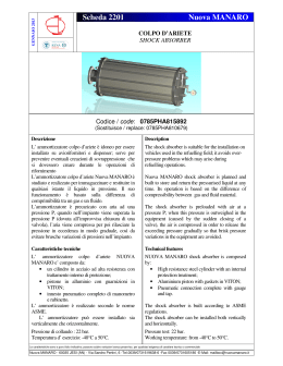
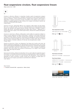
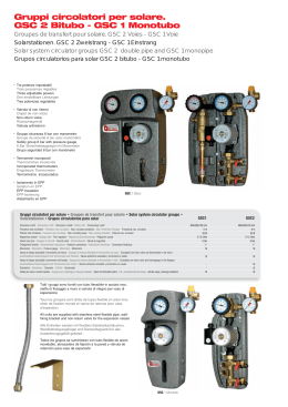
ISTRUZIONI DI MONTAGGIO MOUNTING INSTRUCTION INSTRUCTIONS DE MONTAGE
Codice/Code: H 0135 XXF 11
HONDA NSF 100 '08-'10
Rev. 01
Mod. ISTR. MONT. XX
del 08/03/2010
Pag. 1 / 6
NUMERO DI MATRICOLA
DA INDICARE IN CASO DI RECLAMO
PRIMA LA TUA SICUREZZA !
L’ Ammortizzatore è un importante componente della Moto e in questo manuale
è descritto il metodo corretto per il montaggio di esso.
NOTA BENE: l’Ammortizzatore deve essere installato unicamente presso
un’officina specializzata; in caso di dubbi sulle istruzioni qui contenute, Vi
preghiamo di contattare subito un tecnico Bitubo.
Bitubo non potrà essere responsabile di modifiche apportate Prodotto che non
sono contenute in questo manuale, e che non sono autorizzate per iscritto.
Bitubo inoltre non potrà essere responsabile di una non corretta installazione
del Prodotto.
Leggete attentamente questo manuale, per ottenere dall’Ammortizzatore il
massimo delle prestazioni e del rendimento.
NOTA BENE: la garanzia dell’Ammortizzatore cessa
nel caso in cui venga montato in maniera errata, o
modificato, senza l’approvazione scritta da Bitubo.
Bitubo non potrà essere responsabile di danni al
prodotto o alle persone, in caso le istruzioni contenute
in questo manuale non vengano seguite esattamente,
o in caso il montaggio dell’Ammortizzatore non venga
effettuato presso una officina specializzata, e da
personale qualificato.
BITUBO RACCOMANDA
Le immagini e le indicazioni riportate sono a titolo indicativo; C.d.a. Bitubo si riserva la facoltà apportare qualsiasi modifica o variazione senza alcun
preavviso.
C.D.A. BITUBO s.n.c. – Via A. Volta,24 – 35037 Z.I. Teolo (PD) ITALY – Tel. (+39) 049-990.34.75 (2 linee ISDN)
Fax (+39) 049-990.34.47 – Cod Fisc. e Part. IVA 02007650282 – E-mail: [email protected] - Internet: http://www.bitubo.com
ISTRUZIONI DI MONTAGGIO
1. Mettere la moto su un cavalletto idoneo a sollevare la ruota posteriore da terra. Per lo
smontaggio e dell’ammortizzatore e dei particolari originali, attenersi alle indicazioni
della Casa costruttrice del veicolo (Libretto Uso/Manutenzione – Manuale di Officina).
2. Inserire l’ammortizzatore Bitubo attenendosi alle seguenti indicazioni (Figure 1 - 2):
•
la vaschetta del gas deve essere rivolta verso il basso e rivolta verso la ruota
posteriore;
•
la vaschetta del gas, una volta montato l’ammortizzatore, deve presentare un
angolo pari a 40° a destra rispetto all’asse longit udinale del veicolo.
3. Inserire le viti sugli attacchi superiore e inferiore dell’ammortizzatore ed avvitare i bulloni
originali del veicolo. Per il momento non serrare totalmente i bulloni.
4. Appoggiare il veicolo a terra, quindi serrare i bulloni con le coppie di serraggio prescritte
dalla Casa costruttrice del veicolo (Libretto Uso/Manutenzione – Manuale di Officina).
5. Verificare che durante il movimento della sospensione l’ammortizzatore non interferisca
con alcuna parte del veicolo. In caso contrario allentare il controdado dell’attacco
inferiore (in prossimità della testina porta valvole, Figura 3) e ruotare opportunamente il
corpo dell’ammortizzatore, quindi serrare il controdado.
C.D.A. BITUBO s.n.c. – Via A. Volta,24 – 35037 Z.I. Teolo (PD) ITALY – Tel. (+39) 049-990.34.75 (2 linee ISDN)
Fax (+39) 049-990.34.47 – Cod Fisc. e Part. IVA 02007650282 – E-mail: [email protected] - Internet: http://www.bitubo.com
ISTRUZIONI DI MONTAGGIO MOUNTING INSTRUCTION INSTRUCTIONS DE MONTAGE
Codice/Code: H 0135 XXF 11
HONDA NSF 100 '08-'10
Rev. 01
Mod. ISTR. MONT. XX
del 08/03/2010
Pag. 3 / 6
SERIAL N.
(SEE PAGE 1)
TO BE MENTIONED IN CASE OF CLAIM
FIRST YOUR SAFETY !
The rear Shock is an important component of the motorcycle and this manual
describes the correct way to assemble it.
NOTE: The Rear Shock must be installed exclusively in a specialised
workshop; if you have any doubts regarding these instructions, please contact
a Bitubo engineer straight away.
Bitubo cannot be held responsible for any modifications to the Rear Shock not
described in this handbook or not authorised in writing. Moreover Bitubo
cannot be held responsible for the incorrect installation of shock absorber.
Read this handbook carefully so that you can get the best performance and
efficiency out of the Shock absorber.
NOTE: The warranty for the Shock absorber will be
invalidated by incorrect installation or modifications
carried out without Bitubo’s written authorisation.
Bitubo cannot be held responsible for any damages to
the product or injuries to people if the instructions of
this handbook are not followed to the letter or if the
Fork Spring Kit is not fitted in a specialised workshop
or by qualified personnel.
BITUBO RECOMMENDS
Pictures and notes reported are purely as an indications; C.d.a. Bitubo reserves the faculty to make any modification or changes.
C.D.A. BITUBO s.n.c. – Via A. Volta,24 – 35037 Z.I. Teolo (PD) ITALY – Tel. (+39) 049-990.34.75 (2 linee ISDN)
Fax (+39) 049-990.34.47 – Cod Fisc. e Part. IVA 02007650282 – E-mail: [email protected] - Internet: http://www.bitubo.com
ASSEMBLY INSTRUCTIONS
1. Place the bike on a proper stand in order to lift the rear wheel. For disassembling the
original shock and the original part of the motorbike refer to the vehicle constructor
indications (Use/Service manual – Machine shop manual).
2. Insert the Bitubo shock absorber taking care to the following indications (Figure 1 - 2):
•
the gas tank must look toward the ground and toward the rear wheel;
•
the gas tank, once the shock has been mounted, must be inclined 40° toward
right with respect to the vehicle longitudinal direction.
3. Insert the screws in the upper and lower attack of the shock absorbers and tighten the
original bolts of the vehicle. Do not tighten completely the bolts.
4. Put down the vehicle and tighten the bolts with the torque forces advised by the vehicle
constructor (Use/Service manual – Machine shop manual).
5. Check that during the excursion the shock damping does not interfere with any part of
the bike. Otherwise unscrew the lock nut of the lower head (in correspondence of the
hydraulic adjuster valves, Figure 3) and turn properly the body of shock absorber; hence
tighten the lock nut.
C.D.A. BITUBO s.n.c. – Via A. Volta,24 – 35037 Z.I. Teolo (PD) ITALY – Tel. (+39) 049-990.34.75 (2 linee ISDN)
Fax (+39) 049-990.34.47 – Cod Fisc. e Part. IVA 02007650282 – E-mail: [email protected] - Internet: http://www.bitubo.com
1
Vaschetta gas / Gas tank
2
40°
40
Vaschetta gas / Gas tank
C.D.A. BITUBO s.n.c. – Via A. Volta,24 – 35037 Z.I. Teolo (PD) ITALY – Tel. (+39) 049-990.34.75 (2 linee ISDN)
Fax (+39) 049-990.34.47 – Cod Fisc. e Part. IVA 02007650282 – E-mail: [email protected] - Internet: http://www.bitubo.com
3
Testina portavalvole /
Hydraulic adjuster valves
Controdado / Locknut
Attacco inferiore / Lower clamp
C.D.A. BITUBO s.n.c. – Via A. Volta,24 – 35037 Z.I. Teolo (PD) ITALY – Tel. (+39) 049-990.34.75 (2 linee ISDN)
Fax (+39) 049-990.34.47 – Cod Fisc. e Part. IVA 02007650282 – E-mail: [email protected] - Internet: http://www.bitubo.com
Scarica