lstruzioni
Instructionsheet
Noticetechnique
l;5L,iiJ{",}
GasStopGPL08496
Gas Stop Metano08497
fdd#ie
Gas Stop GPL 16591
Ga s Sto p G PL 1 6 59 1 .8
Gas Stop Metano 16592
Gas Stop Metano 16592.8
C (@
Gas Stop GPL, rivelatoreelettronicodi gas GPL
con segnalazioneacusticaed ottica e comando
di elettrovalvola,alimentazione230 V- 110%
50-60H2-3moduli
Gas Stop GPL, the electronicLPG gas leakage
detector with acoustic and optical signals
and control on solenoidvalve, supply voltage
230 V- =10% 50-60Hz - 3 modules
Gas Stop GPL, détecteur électronique de gaz
GPL avec signalisation acoustique et optique
et action sur électrovanne, alimentation 230 Vt10% 50-60 Hz - 3 modules
Installazione
perle operazioni
Rvolgersi
a tecnici
autorizzati
di
installazione,
manutenzione
ordinaria
e straordinara
e
pera messa
tuoriservizlo
dell'apparecchio.
Installation
Apply10author
zedtechnic
ansforall nstallation
and
anyroutine
andnon-routlne
mainîenance
operation
as
Installation
Veuilezvousadresserà des technlclens
agrééspour
les opératrons
d instalation,d'entreten ord naireet
extraordinaire
el pour la misehorsservicede I'appareil.
wellas for the replacernent
of the detectorat the end
of ts ifeìime.
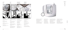
I r ve atore deve essere installato ulilizzando I relativi
accessor (scatole,support , placche) in una pos z one
^te essata dalla c rcolazrone natJra
e oe I ana. ao Lna
distanza non superiore a 3-4 m da caldaie,
scaldabagni, fornelli, bombole di gas e ad una
distanza di 20-30 cm dal piano di calpestio (figura A).
ll rvelatore non deve essere instaliato:
. al aperto
ino a fornelli e aooarecchr di cottura
rino a lavandini e rubinetti d'acqua
. v c no ad asp ratorld'ar a, finestre,ventilatori,ecc.
The detectormust be installedin a positionwherethere
. a g o o d .n a l L r acl r c u l aol ^ o [ a r ' .r s r r g l h c î e c e s s a l
(boxes,supports,plates),at a maximum
accessories
distanceof 3-4 m from boilers,water heaters,
cookers,gas cylindersand at a distanceof 20-30cm
from floor level (figure A).
The detectormust not be rlstalled:
. n the open air
. nearcookersand otherequipmentusedfor cookng
. nearsinksand watertaps
. nearair vents,windows,ventlators,etc.
Le détecteurdoit ètreinstalléen ut lisantlesaccessolres
(boîtes,supports,p aques)dans un
correspondants
endroltà circulation
natureÌle
d'a r, à une distance ne
dépassant pas les 3-4 m de chaudières,chauffe-eau,
réchauds,bouteillesde gaz et à une distancede
20-30 cm du plan de piétinement(figureA).
Le détecteurne doit pas étre installé:
. en plernarr
. oresde 'ecl'audset de cu sinieres
. oresde lavabosel de rob nels
r presd'aspirateurs
d a r, fenètres,ventiLateurs,
etc.
Gas Stop Metano, rivelatoreelettronicodi gas
metano con segnalazioneacustica ed ottica
e comando di elettrovalvola,alimentazione
230 Y- =10o/o
50-60Hz - 3 moduli
Gas Stop Metano, the electronic methane gas
leakage detector with acoustic and optical
signals and control on solenoid valve, supply
voltage 230 V- x.10o/o50-60 Hz - 3 modules
Gas Stop Metano, détecteur électronique de
gaz méthane avec signalisation acoustique et
optique et action sur électrovanne, alimentation
2 3 0 Y - x . 1 0 o / o5 0 - 6 0 H z - 3 m o d u l e s
lnstallazione
Bivolgersi
a tecnci autoÍzzatperle operazion
d
nstallazione,
manutenzione
ordinaria
e straord
nariae
per1amessafuoriservziodel'apparecchio.
Installation
Applyto authorized
technicans for all instalationand
any routineand non routinemarntenance
operatonas
lnstallation
Veuillez
vous adresserà des technciensagrééspour
les opérationsd'ìnstalaton, d entretlenordinaireet
eÀlao'd rai'e et pour la r.e l-orcsè'vr.ade I appareil.
^,ól .<
l l r \ e a l o r e d e v e e s s e r e n s t a l l a t oL r , r z z a n d oi r e l a t r r
\ùLarurú
. )uvpurr,
p,dLLr
úl il
ur d vuJr/ru
f^/
rLh' òc , s' òP^, loàu. èqm
, ò ^ l, c
^f
rh.
n^,^.
.^'
îr
rts-
-ni
of its lifet me.
The detectormust be nstalledin a positionwherethere
s a good, naturalcirculatonof air, usingthe necessary
(boxes,supports,plates),at a maxamum
accessories
distance of 3-4 m from boilers,water heaters,
cookers, gas cylinders and at a distance of 20-30 cm
from ceiling level (figureB).
The detectormust not be insÌalled:
. In tne open arr
. nearcookersand otherequrpmentusedlor cooking
. nearsrnksand watertaps
. neara r vents,wìndows,vgntilators,
etc.
,F
î t e r e s s d l d d a l d c r r c o l a z o r e n d î L r a e o e , a r i a ,a d J n d
distanza non superiore a 3-4 m da caldaie,
scaldabagni, fornelli, bombole di gas e ad una
distanza di 20-30 cm dal soffitto (figura B).
'
,e atore non deve essere instalato:
apeno
' ' c i n o a f o r n e l l ie a p p a r e c c h d c o t t u r a
. vicrno a lavandin e rubinett d'acqua
. vicino ad asp rator d aria, fnestre, ventllator, ecc.
lesaccessores
Le détecteurdoit ètreinstalé en utiiìsant
(boîtes,suppods,plaques)dans un
correspondants
endrot à circulation
naturelle
d'air.à une distance ne
dépassant pas les 3-4 m de chaudières, chaufie-eau,
réchauds,bouteillesde gaz et à une distancede
20-30 cm du plafond (figureB).
Le détecteurne doit pas ètreinstalé:
. e n p l en a r r
r n.o<
.-la ràe\at
o nroc
do
l-' ih^c
11- o
^a,
èr da
'Ici
iefes
rohinal<
. O r e sd a b p r a r e u ' Sd d r . f e î e i l e s , . e r l a l e L ' S ,e t ( .
20130
cm max
., VIMAR
',ral\i \o','embre32 - 36063 Marostca Vl
T e . 0 4 2 a . , 1 8 8 . 1 0F0a x0 4 2 44 8 8 . 1 8 8
hito)i'www.vn.rart
tNilúkd._
I 167-8623071
l
l
From abraad dial
u-
Mattq-r
dppct€r
3 9 . 0 4 2 4 . , + 81080.
9!116591 CE 98!6
l/aoe I ta,,, V MAF VarostrcaV
ATTENZIONE!
ll rivelatoreda Lei installatoha una durata di 5 ANNI
dal momento in cui viene installato.
Si ricordi di indicare la data di sostituzione
nell'appositospaziosul fronte dell'apparecchioe
a pag. 49 del Librettoistruzioniper I'utente.
ATTENTION!
The detector you have installedhas a lifetimeof 5
YEARSfrom the time it is fitted.
Rememberto indicatethe expiry date in the special
space on the front of the device and on page 49 of
the User's InstructionBook.
ATTENTION!
Votre détecteura une durée de 5 ANS à partir du
moment où il tété installé.N'oubliez pas d'enregistrer
la date d'échéancesur l'étiquettesur le front de
I'appareilet à la page 49 du Guide à l'Usageet à
I'Entretien.
Verificareprima dell'installazioneche nel rivelatore
sia presentela resistenzadi carico collegataai
morsetti 6 e 7.
Before installingthe equipment,check that the load
resistor is present,connectedto terminals6 and 7.
Contrólezavant d'installerque la résistancede
charge connectéeaux bornes 6 et 7 soit présente
dans le détecteur.
Per il collegamentodella elettrovalvolaVIMAR
16590 o di elettrovalvolenormalmenteaperte (NO)
a riarmo manuale12V d.c. 13 W con energiadi
eccitazione non superiore a 0,4 Joule utilizzarc i
morsetti6 e 7 rimuovendola resistenzadi carico.
Per il collegamentodi elettrovalvoledi altro tipo ed
eventualisegnalazioniaggiuntivedi allarmeutilizzare
i morsetti3-4-5 relativia relé di uscita a contatto
pulito portata 10 A max e non rimuovere la resistenza
di carico dai morsetti 6 e 7.
When connectingup the VIMAR16590solenoid
valve or the manuallyresettable12 V d.c. 13 W
solenoidvalves (usuallyopen (NO)),with maximum
excitationenergy of 0.4 joule, use terminals6 and 7
removingthe load resistor.
When connecting up other types of solenoidvalves
and any additionalalarm signals,use the output
relaywith change-overcontact terminals3-4-5,
maximum capacity 10 A, and do not removethe
load resistorfrom terminals6 and 7.
Collegamenti
. nìorsettL - N: alimenÌazione
230 V- r10% 50-60 Hz
. morsetti6 - 7: collegamento
eiettrovalvola
VIMAR
16590o elettrovalvola
a riarmomanualeNO 12 V d.c.
13 W con energiadi eccitazione
non superiorea
0,4 Joue previarimozionedeJlaresistenza
di carico
. morsett3 - 4 - 5: relédi uscta a contattopulito n
scanb o oe' uorlegalleîloo segnaazrorraggiunlt\
e
di allarmee di elettrovalvole
di troodiversoda ouela
sopraindrcata(rnorsett3-4 se normalmente
chiusa;
morsett4-5 se norrnalrnente
aoerta)
Connections
. terminalsL - N: voltagesupply230 V- t10% 50-60 Hz
. Ì e r m i n a l6s - 7 : c o n n e c t i oVnI M A R1 6 5 9 0s o l e n o i d
valveor NO l 2 V d.c. l3 W manuallyresettablesolenoid
valvewth excitation
energyof 0.4 Jouleafterremovìng
the load reslstor
. termlnals3 - 4 - 5: outputrelaywith change-over
contactfor conneclionof extraalarmsignalsand for
solenoidvalveswhichd fferfromthe one indcated
above(termna s 3 4 if usuallyclosed;terminals4-5 if
usuary open)
Tutte le elettrovalvoledevono esseredi tipo a riarmo
manuate.
All the solenoidvalves must be of the manually
resettable type.
QualoraI collegamento
dell'elettrovalvola
o della
resistenza
ai morsett6 e 7 non fossecorretto.I Ied
g al o :\ sl accendefissornentreI led verde. , continua
f the solenod valveoLlhe resistors not propedy
connectedto terminals6 and 7, the ye low ed 1. w 11
stayon whilethe greenled r ' wi I contlnueto flash,
indicatinga faut.
a laî-pegg are,îdrLonoo
dî ú'o-ar.d.
Sr possonocollegarepru|velatoriin uno sÌessoedificio
un'unicaeettrovalvola.
lambienlidversi)i qual comandino
In tal caso I'alimentazionedi ogni rivelatore deve
essere portata sui morsetti L e N rispettando la
polarizzazione(L con L; N con N) e le uscite per
I'elettrovalvoladi ogni rivelatore devono essere
collegatein parallelotra loro, rispettandola
numerazionedei morsetti (6 con 6; 7 conTÌ'.
In tal modo una fugadi gas in uno qualsiasidegli
a n l l r e ^ Lpi . o \ o c h e ' al b l o c c o6 . a - a r s g a z 6 p6g9 l g a s
chrudendoI'elettrovalvola,
mentrela segnaazione
o t t r c o / a c u s t cdae l r v e a t o r ec h e h a n v i a t ol ' m p u l s o
e e t t r c od c h u s u r ai n d i c h e riàn o u a l ea m b e n t es i e
manifestata
la fuga d gas (vedereesempiofigura2).
It rs possrble
to connectup rÌore thanone detectorìn
tfresamebuildng (different
rooms),controlling
one s ngle
solenoidvalve.In this case, the voltage supply of
each detector must be connectedup to terminalsL
and N, respectingpolarisation(L with L; N with N)
and the outputs for the solenoidvalve of each
detector must be parallelconnected,respectingthe
numberson the terminals(6 with 6; 7 with 7).
n thisway, a gas eak n any of the roomswillcause
the gas supplyto be interrupted,
closingthe solenoid
valve,whie the opt cal,/acoustic
warningon the detector
responsble for the e ectronicswitchoff pulsewillindìcate
the room wherethe gas leakhas takenpiace(see
examplefigure2).
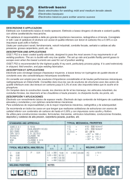
Esempi di collegamento
'1
: instalazionedi un s ngolor ve atorecon elettrovalvola
V N / A R1 6 5 9 0o e q u i v a e n t i
Examplesof connections
1: installation
of one,single
detector
w th V l\,4AR
16590
solenoidvalveor equva ent
2:Ìnstallazione
di piu rivelatorl
n para!eocon elettrovalvola 2:installation
of morethan one paralieldetectorwth
V I M A R1 6 5 9 0o e q u i v a l e n t i
VIN/AR16590solenoldvave or equlvalent
3r nstallazione
di un singolorivelatore
con elettrovalvola 3: installation
of one. singledetectorw th manualy,
a n a r m om a n u a l eN C 2 3 0 V - l 1 2 V - i I 2 V d . c . 1 0 A
r e s e t t a b es o l e n o lvda l v eN C 2 3 0 V - / 1 2 V - i 1 2 V d . c .
max su uscrtaa rel-ó
10 A max on reay output
,1:instalaz one dr un singoo rivelatore
con elettrovalvola 4: instaliation
of one, singe detectorwith manualy
a n a r m om a n u a l eN O 2 3 0 V - l l 2 V - l 1 2 V d . c . 1 0 A
r e s e t t a o lseo e n od v a l v eN O 2 3 0 V - / 1 2 V - ' / 1 2V d . c .
max su usota a relé
1OA max on relayoutput
Pour la connexionde l'électrovanneVIMAR 16590
ou d'électrovannesnormalementouvertes(NO)à
réarmementmanuel 12 V c.c. 13 W avec énergie
d'excitation ne dépassantpas 0,4 Joule, utilisezles
bornes 6 et 7 en enlevantla résistancede charge.
Pour la connexiond'électrovannesd'un autretype et
signalisationséventuellessupplémentaires
d'alarme
utilisezles bornes3-4-5 correspondantà des sorties
à relaisà contacl inverseurportée 10 A maxi et
n'enlevezpas la résistancede charge des bornes
6et7.
Connexions
. bornesL - N: alimentation
230 V- t10% 50-60Hz
. bornes6 - 7: connexionélectrovanne
VIIVAR16590
ou électrovanne
à réarmementmanuelNO 12 V d.c
13 W avecénergied excltationne dépassantpas
O . 1- 1 ù v ^v , a
JP
. bornes3 - 4 - 5: sortieà relas à contaciìnverseur
sanspotentiepour a connexonde sgnalìsations
-r'..|èmènlrr'a<
d :l-'mo
ot d'olortrn.,rnno
dlfférentde celleindiquéec -dessuslbornes3-4 s
normaenrentfermée;bornes4-5 si normalemenî
ouvene)
Toutes les électrovannesdoivent étre du type à
rearmementmanuel.
S ' d o a î p \ t o . d e e l e c t r o . a n îo
eL d e c r e s i s r a î c e
a L ' b o r a e s6 e l / î e s e . dI o d s c o - e . l o . a l e o_ a u n e
s al urnerade manlèrefixetands que la led verte1,
contrnuera
à clignoteren indlquantune défaillance.
Pl-s;eu'd
s e r e c l e u 'p
s e J . e - l e l r e n s l a t ' eos a n su a
mèmebàtiment(ocauxdifférents)
pour la commande
d'uneseuleélectrovanne.
Dans ce cas, l'alimentation
de chaque détecteurdoit ètre sur les bornes L et N
avec respect pour la polarisation(L avec L; N avec
N) et les sorties pour l'électrovannede chaque
détecteurdoivent étre connectéesen paralfèle,en
respectantla numérationdes bornes (6 avec 6; 7
avec 71.
I a O esop,e d^ gd7daîS uî localqLp'conqlre
ou
un détecteura été nstaié déterminera
I arretde
I a imentaton du gaz en fermantl'éiectrovanne,
tandis
que la signalsatlonoptique/ acoustiquedu détecteur
ayantenvoyél' mpulsionélectrque d'atrét nd querale
local ou la présencede gaz a eté détectée(voirexemple
f g u r e2 ) .
Exemples de connexion
1: nstallation
d'un détecteuravecélectrovanne
VIN/AR1
6590 ou équivaent
2: inslaiat on de plusieursdétecteursen parallee avec
électrovanne
VlN,4AR
16590 ou équva ents
3: nstalationd'un détecteuravecélectrovanne
à
r é a r m e m e nmt a n u eN
l C 2 3 A V - 1 1 2 V - 1 1 2 Vd . c .
10 A maxisur sortlepar relais
4: installallon
d un détecteuravecólectrovanne
à
r e a r r n e m em
n ta n u eN
l O2 3 A V - / 1 2 V - / 1 2 Yd . c .
10 A maxlsur sodiepar relars
L-
2
L
N
Eleltrovalvola NO 16590
NO solenoid valve 16590
Electrovanne NO 16590
Elettrovalvoa NO 16590
NO solenoid valve 16590
Eìectrovanne NO 16590
3
4
Resrstenza d carico
Fesìstìve oad
Resrstenza di carico
Resistve load
x
230V1 2 V -/ 1 2 Vd . c .
l0Amq
EÌettrovalvolaNC
NC solenod valve
Electrovanne NC
230V1 2 V -/ 1 2 Vd . c
10Ama
Messa in servizioe controllo di funzionamento
. control
areches a presente
nel' mpianto
Una
Installationand operatingcontrol
. checkthatthepantisfittedwitha gascut-out
e ettrova vo a di ntercettazìone del gas e che s a
regolarmente co legata
. c o l e g a r e l ' a i m e n t a z r o n e2 3 0 V - t l 0 o ó 5 0 6 0 H z
ar morsett L e N: i tre ed si accendono
.or''eî oo.aîedrento pet . rcd 2 s e. dopo Ln brcve
segnalesonoro, sr spengono per raccendersrsecondo
soieno d vaÌve and that t ls correctly connected
. c o n n e c t t h e 2 3 0 V - r l 0 % 5 0 - 6 0 H z v o l t a g et o t h e
terminas L and N: the three eds will come on togeÌhef
lor about 2 seconds, and, after a shod buzzing sgnal,
they will go out. After this. rhey !v ll iglìt up uccorilif g
J I
J
l, !
f_ up
J Ue
ilvcta.O
e.
A questo punto il rvelatore esegue una fase di
rerDo //a,, o-e (PBE BISCALDO de ld oJ ata or
c rca 60 s ne la qua e sono inlb t comandi
: uesta èsee
a ' e e t l o \ a \ o o e d a . o r z d r o r eq
segnalata dal lampegg o contemporaneo de ed
v e r d e . - ' e g a lo l
. trascorso ltempo di pre-riscaldoìl ed galo i si spegne,
nrentre il led verde .' comincia a lampeggiare
idamente per circa 3 min ad tndrcare che il
- atore funziona n modalità TEST ed e pronto per 1
controrlo di funzionamento. Durante questo ciclo di
3 minuti non sono attivi i ritardi di pre-allarme e di
"Uso
allarme (vedi lbretto
e l\,4anutenzione"),
ma il
. ò l A l O I s .n p r e 5 e î 1 é O e Q o : C j O ' O , a .d l l r v a
'allarrne
'ele'ttrovalvola
direttamente
ed il blocco del
. tenere a bombo etta Gas di test VlNilAR"0l899 vert cale
con a va vola verso l alto e l erogatore rlvo Ìo verso la
gnglrarnfenoredel nvelatore.ad una dlstanza di circa 10 cm
. azionare una sola volta 'erogatore monodose cal brato
per iberare ll gas di test: il rvelatore segnala l'allarme
azronando I ronzatore, accendendo il led rossoér e
comandando la ch usura della e eltrovalvola coliegata
c o n s e g n a e a i m p u l s r i p e i u t io g n i 2 O s s ! m o r s e t t l6
e 7 e commutazone del contatlo del relé d uscita
lrnorsett 3-4-5)
Al o spegnimento de led rosso A (fine delo stato dl
a arme), vene disattvato il ronzatore,commutato I
coftatto sui morsettt 3 ,1 5 e cessano gI mpu si a
'ììcrsetli 6 e 7.
Ad esìto posit vo del contro lo di funzronamento
D ' | S L J è e r o g d ? O ^ ed e g d > d g e f ' d o s L . i o r r o
nìanuale dell e ettrovaivola.
Nota
I corretto funzronamentode fve atore e sempre indicato
ca arÌìpegg o de ed verde . . Se i ed verde r rimane
costanlemenfe acceso o sp-.nto s gnifica che il rivelatore
non è piu funzionante.
to the code of the detector.
A t t h i s p o i î t . t h e d e t a (r o r r a r n è s o L l a l i n . î g p l ' a s e
(PRE-HEATING)of about 60 seconds during which
the commands to the solenoid valve and Ihe buzzer
are inhrbrted:th s phase is signalled by the green . r
and yellow ,L eds wh ch flash on and off together
. a t t h e e n d o f t h e p r e h e a t i n gp h a s e t h e y e l o w l e d A
wì | go out wh le the green led il-ìstarts flashing
quickly for about three minutes to ndicate that the
detector s running in TEST mode and that t s ready
for the operating check. During this 3-minute cycle
the pre-alarm and alarm delays are not active (see
'Us^
Jrd Varîlènaî.e bookel). bur l"e dere. o' r I
switch on the alarrn directy and ntetrupt the solenoid
va ve n the presence of test qas
. hold the "VlN/IAFtest gas' 01899 cyl nder in a vertlcal
position wth the vave towards the top and the nozzle
turned toward the lower grill of the detector, al a
distance of approx. 10 crn
. n,Òcc .l-'èqr-Òc rl, (a , .lih,r.cd nozzle once lo release
ti'e test gas: il-e dele.ror s gnal" aî ala'î b) switcl-,îg
^n
Ìho
h
r77or
ldhr,nn
I n
lhè,èd
lèr1 a
:nd
c-r
nn
-
command to c ose the connected solenoid valve with
r n rl<èc Òîà rano).orl c .". .O .eCOnd>On tefm ndls
6 and 7 and by commutating the output relay contact
(terminals3 4 5)
When the red led.6r goes out (end of the alarm state),
Ihe lxzzer is switched off, Ìhe contact on terminals 3-4-5
is comrnutated and the pulses to terminals 6 and 7 cease.
lf the operating check is successful, the gas supply will
breswitched on aga n by resettiÌrgthe solenoid va ve
manuary.
Note
When the detector is running correctly the green led t-ì
w ll always flash on and off.
f the green led i,l rerfains on without flashing or if t s
off this means that the detector is no longer working
properly
Mise en marche et contróle de fonctionnement
. vérlfÌer
la présencedansl'installat
on d'uneélectrovanne
d ìnterception
du gaz et sa connexon correcte
. connecter'alimentation
230 V- t 10%50-60 Hz aux
bornesL et N: lestroisledss allumenten méme
ten ps pendantenvrron2 secondeset. apresun bref
ù 9' id
duuuùil9uc.
c,'c)
) E,s 9l
ar -
r l, mó.l
dó
noJ\edu sui./antLn Lode propredJ delecleJr.
Pour60 secondesenviron,le détecteursuit une phase
d e l e m p o r s a t i o(.D F E C t A L t r F A GpEe) n d a n ta q - e l e
et sur e ronfleur
es commandessur l'électrovanne
soal Trè.dtes: cele phaseest nd qJee par le
crg'ìoterìeît sir-r-lta^e
des eds rerte et aLne
. apres a phasede préchauffage.
a led jaune1
s éteint,tands que la led verte --ìclignoterapidement
pendant envíron3 minutes pour indiquerque e
détecteurest en modaitéTESTet qu'l est prét pour
le contrólede fonctionnement.
Pendantce cycle de
3 minutes,les délais d'action de préalarmeet
d alarmene sont pas actifs (voir"Gude à 'Usage
^i
i
E^r,^,^^_\
s ú " / . c
l^À^,^/r^
. Y r P r c ) t r r u e u u 9 a u c
test,aclivedirectement'alarmeet fermel'électrovanne
. tenirà envlronl0 cm du déiecteurla cailouche
"Gaz test VllVlAR'
de
01899 en poston verlicale
a\ec >d volve er haLl et le d stflbLt.Lr d'rg-
vgr,
a grilleinférieure
. '.i'è sortr Lqe ceue do5oca ibreede ga7de resl: e
dé'tecteur
actionnelalarmepar le ronfleur,
allurnea led
rougeA et commandea fermeturede | électrovanne
c o r . e c t e pa L s g r a a n p r l s o r . s e t e p e ' a t lt o - t e Se s
20 secondessur es bornes6 et 7 et la commutaton
du contactde la sorte par reais lbornes3 4 5).
O . a r d l a e d o l g e c o e , î l ' r î d p I e r a td a r aT e ) . e
ronfleurest désactivé.e contactsur lesbornes3 4 5 est
c o n n L l e e - l e sr î p - l > o n sa L r {b o î è s 6 e t / c e s , e a t .
A
r rn
^,
r--i
^-
^.^r.^l^
ilrt-
^Òeirife
remettrele débitrégulierdu gaz en agissantsur le
réarmement
manue de I éectrovanne
Note
Le fonctionnement
correctdu détecteurest toujours
ndiquépar e clgnotementde a 1edverte l- .
S l a e d \ e d e e s r c o î s t a ' r î e n I a | . n . . o L e l en t e ,
le détecteurn'est plus en état de fonctionner.
Regoledi installazione
. instailazione
deveessereeffettuatan conformitàalle
n o r m eC E Iv g e n t i
o primadi operaresull'impianîo
toglieretensioneagendo
sull'nterruttoregenerale
. verificare
che la sezionedei conduttori di
alimentazionesia adeguataal carico alimentato
ed in ogni caso non inferiorea 1,5 mm'
. serrareaccuratamente
i conduttorinei morsetti,
possonoprovocare
in quantoserraggìimperfetti
suriscaldamenti
fino a temoeraturesufficientt
ad
nnescareun Incendro
Conformità normativa
Direttiva"8T", NormaUNI CEI70028;Direttiva"EMC",
N o r m eC E IE N 5 0 0 8 1 - 1C
, E IE N 5 0 0 8 2 - 1C
; ircolari
l\linisteriali
(N/lCA)n' 161892del
IndustraArtigianato
2 7 . 4 7 . 1 9 9 e4 n ' 1 6 2 4 7 3d e l2 4 . 1 2 . 1 9 9 4
NOTA
I']NSTALLAZIONE
DEL BIVELATORE
DI GAS NON
ESONERADALL'OSSERVANZA
DI TUTTELE REGOLE
RIGUARDANTI
LE CABATTERISTICHE,
L'INSTALLAZIONE
E I'USO DFGLIAPPARECCHÌ
A GAS,LA VENTILAZIONE
DEILOCALIE LO SCARJCO
DEIPRODOTTI
DELLA
COIVBUSTIONE
PRESCBITTI
DALLENORNIEUNI
ATTUATIVE
DELL'AFT,3 DELLALEGGE]OB3/71E
D A I. F D ' S P O S I Z , OD
\ I rL f C G E
Installation rules
. the installation
must be doneaccordingÌo in force
italianCEIspecifications
(orequivalent
rulesfor
electricalinstallations
of buildings)
. disconnectthe ma ns actingon the mainswitch
beforeoperatingon the system
. use the yellow/green
insulated
conductorsonlyfor
the connection10the earthingcircuit
. verityif the supply conductorscross-sectional
area is sufficientfor the feeded load, in any case
it shall never be less than 1,5 mm'
. clampfully,with care,the conductorsin the terminals;
fauty claî-p.nqScan caJSete.foe'aîLre1igg5rrgh
enoughfor a firersk
Règles d'installation
.l'installationdoit étreetfecluéeseionles normes
italiennes
CEIen vigueur(ou normeséquivalentes
pour les installalions
électriques
des bàtiments)
. couperI'alimentalon
en agissantsur I'interrupteur
généralavantd'intervenir
sur l'installation
o utiliserles càb'lesisolésde couleurjaune/verte
seulemenlpour la connexronau circuitde terre
. vérifìersl la section des conducteurs d'alimentation
est suffisante pour la charge alimentée,elle ne
doit quand mème jamais étre inférieureà 1,5 mm,
. serreries conducteursdans les bornesavecsoin;
un mauvaisserragepeut provoquerun échauffement
excessifavecrisqued'ncendie
Conformity to laws and standards
"LV"Directive,ltalian
standardUNICEI 70028;"EMC"
D r e c t i v es, t a n d a r dC
s E IE N 5 0 0 8 1 - 1C
, E E N5 0 0 8 2 - ' 1
Conformité aux normes
Directlve"BT', NormesitaliennesUNICEI70028;Duective
'EMC",Normes
CEIEN 50081'1, CEIEN 50082-1;
NOTE
THEINSTALLATION
OF THEGASDEIECTORDOES
NOTE(EN/PTFROÍVTHESTRICTOBSERVATION
OF
THEREQUIREMENTS
ON THECHARACTERISTICS,
THE
INSIALLATION
ANDTHE USEOF GASEQUIPIVENTS,
ON THE VENTILATION
OF THEAMBIENTAIRAND THE
E(HAUSTOF THE PRODUCTS
OF CON/BUSTION,
AS
PRESCBIBED
BY UNI-CIG
SECURITY
BULESANDBY
IHE IN FORCEPROVISIONS
OF THELAW,
NOTE
L'INSTALLATION
DU DETECTEUR
DE GM NE
DISPENSE
PAS D'OBSERVER
LESREGLESSUR LES
CARACTERISTIQUES,
L'INSTALLATION
EI L'USAGE
DESAPPAREILS
A GAZ, DE LA VENTILATION
DES
LOCAUXET DE LA DECHARGE
DESPRODUITS
I
LA COIVBUSTION,
COIVIVEPREVUPAR LES
NORIVESDE SECURITE
UNI-CIGEI PAR LES
DISPOSITION
DS
E L O IE N V I G U E U R .
Scaricare