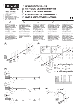
SAFEBEAM FOTOCELLULA - PHOTOCELL - PHOTOCELLULE PHOTOZELLE - FOTOCELULA SAFEBEAM I La fotocellula ad autoallineamento Safebeam, composta da un Trasmettitore ed un Ricevitore a raggi infrarossi modulati, è un dispositivo di sicurezza. L’oscuramento del fascio luminoso, provoca il cambiamento di stato del contatto elettrico sul Ricevitore. Alimentazione Assorbimento Portata max. IP Tempo rilevamento ostacolo 24VDC / 24VAC Tx= 20mA Rx= 30mA 20m 54 13mSec Tipo contatto e portata Tipo allineamento Angolo di autoallineamento Temperatura ambiente Installazione NC 60VA / 24W automatico +/- 7° (20 m) +/- 13,5° (5 m) -20°C / +55°C a parete GB The Safebeam self-aligning photocell is a safety device comprising modulated infrared Transmitter and Receiver. Breaking the path of the beam causes a switch in the status of the electric contact on the Receiver. Power supply Absorbtion Sensing range IP Obstacle detection time 24VDC / 24VAC Tx= 20mA Rx= 30mA 20m 54 13mSec Contact type and rating NC 60VA / 24W Type of alignment automatic Self-alignment angle +/- 7° (20 m) +/- 13,5° (5 m) Operating ambient temperature -20°C / +55°C Installation wall-mounting F La photocellule avec alignement automatique Safebeam, composée d’un Emetteur et d’un Récepteur à rayons infrarouges modulés, est un dispositif de sécurité. L’interruption du faisceau lumineux, provoque le changement d’état du contact électrique sur le Récepteur. Alimentation Absorption Portée max IP Temps détection obstacle 24VDC / 24VAC Tx= 20mA Rx= 30mA 20m 54 13mSec Type contacts et portée Type d’alignement Angle d’auto-alignement Température d’utilisation Installation NF 60VA / 24W automatique +/- 7° (20 m) +/- 13,5° (5 m) -20°C / +55°C en saillie D Die Photozelle „Safebeam“, die über eine Selbstausrichtungsfunktion verfügt, besteht aus einer Sende- und Empfangseinheit mit gemodelten Infrarotstrahlen und wird als Sicherheitsvorrichtung eingesetzt. Durch die Abdeckung des Lichtbündels wird eine Statusänderung des elektrischen Kontakts auf der Empfangseinheit verursacht. Versorgung Verbrauch Kapazität max. Schutzgrad IP Erfassungszeit Hindernis 24VDC / 24VAC Tx= 20mA Rx= 30mA 20m 54 13mSec Kontakttyp und Leistung NC 60VA / 24W Ausrichtung automatisch Winkelspanne der Selbstausrichtung +/- 7° (20 m) +/- 13,5° (5 m) Temperatur am Aufstellungsort -20°C / +55°C Installation Wandinstallation E La fotocélula de autoalineación Safebeam, compuesta por un Transmisor y un Receptor por rayos infrarrojos modulados, es un dispositivo de seguridad. Al obscurecerse el haz luminoso, cambia el estado del contacto eléctrico en el Receptor. Alimentación 24VDC / 24VAC Absorción Tx= 20mA Rx= 30mA Capacidad máx. 20m IP 54 Tiempo de detección obstáculo 13mSeg Tipo de contacto y capacidad NC 60VA / 24W Tipo de alineación automática Ángulo de autoalineación +/- 7° (20 m) +/- 13,5° (5 m) Temperatura ambiente -20°C / +55°C Instalación en pared 1 I AVVERTENZE •Attenzione! È importante per la sicurezza delle persone seguire attentamente tutta l’istruzione. Una errata installazione o un errato uso del prodotto può portare a gravi danni alle persone. •Leggere attentamente le istruzioni prima di iniziare l’installazione del prodotto e conservarle per riferimenti futuri. D HINWEISE •Achtung! Zur Gewährleistung der Sicherheit der Personen müssen unbedingt alle Anweisungen befolgt werden. werden. Die unsachgemäße Installation oder der unsachgemäße Gebrauch des Produkts kann zu schweren Personenschäden führen. •Vor der Installation des Produkts die Anleitung aufmerksam durchlesen. Die Anleitung ist sorgfältig aufzubewahren, damit sie auch zu einem späteren Zeitpunkt konsultiert werden kann. GB IMPORTANT NOTICE •Warning! In order to ensure personal safety, it is important that all instructions be carried out to the letter. Incorrect installation or use of product could cause serious personal injury. •Before attempting installation, read the instructions carefully and store in a safe place for future reference. E ADVERTENCIAS •Cuidado: Es importante para la seguridad de las personas seguir atentamente todas las instrucciones. Una instalación equivocada o un erróneo uso del producto puede ocasionar graves daños a las personas. •Leer atentamente las instrucciones antes de iniciar la instalación del producto y conservarlas para referencias futuras. F CONSIGNES •Attention ! Pour que la sécurité des personnes soit assurée, il est important de suivre scrupuleusement toutes les instructions. Une mauvaise installation ou une mauvaise utilisation du produit peut causer de graves dommages aux personnes. •Lisez attentivement les instructions avant de commencer l’installation du produit, et gardez-les pour pouvoir éventuellement vous y reporter par la suite. 2 I GB DICHIARAZIONE CE DI CONFORMITA’ Fabbricante: FAAC S.p.A. Indirizzo: Via Benini, 1 40069 - Zola Predosa BOLOGNA-ITALIA EC COMPLIANCE DECLARATION Manufacturer: FAAC S.p.A. Address: Via Benini, 1 40069 - Zola Predosa BOLOGNA - ITALY Declares that: The active optoelectronic safety device model SAFEBEAM Dichiara che: Il dispositivo di protezione attiva opto-elettronico mod. SAFEBEAM •complies with the essential safety requirements of the following directives : •è conforme ai requisiti essenziali di sicurezza delle seguenti direttive : 73/23/CEE e successiva modifica 93/68/CEE 89/336/CEE e successiva modifica 92/31/CEE e 93/68/CEE 73/23/EEC and subsequent amendment 93/68/EEC 89/336/EEC and subsequent amendment 92/31/EEC and 93/68/EEC Additional note: These products have undergone tests in a typical uniform configuration (all products manufactured by FAAC S.p.A.). Nota aggiuntiva: Questi prodotti sono stati sottoposti a test in una configurazione tipica omogenea (tutti prodotti di costruzione FAAC S.p.A.). Bologna, 1 January 2000 Managing Bologna, 01 gennaio 2000 L’Amministratore Delegato Director A. Bassi A. Bassi F D DECLARATION CE DE CONFORMITÉ EG-KONFORMITÄTSERKLÄRUNG Fabricant : FAAC S.p.A. Der Hersteller: FAAC S.p.A. Adresse : Anschrift: Via Benini, 1 40069 - Zola Predosa BOLOGNA-ITALIA Via Benini, 1 40069 - Zola Predosa BOLOGNE - ITALIE Déclare que: erklärt: le dispositif de protection active optoélectronique mod. SAFEBEAM die aktive optoelektronische Schutzeinrichtung Mod. SAFEBEAM •est conforme aux règles de sécurité visées par les directives suivantes: 73/23/CEE, modifiée 93/68/CEE 89/336/CEE, modifiée 92/31/CEE et 93/68/CEE •entspricht den wesentlichen Sicherheitsanforderungen folgender Richtlinien: 73/23/EWG und nachträglicher Änderung 93/68/EWG 89/336/EWG und nachträglicher Änderung 92/31/EWG sowie 93/68/EWG Remarque supplémentaire: Ces produits ont été soumis à un test dans une configuration typique homogène (tous les produits sont de fabrication FAAC S.p.A.). Zusatzbemerkung: Diese Produkte wurden in einer typischen und einheitlichen Konfiguration (Fabrikat der Produkte durchgehend FAAC S.p.A.) geprüft. Fait à Bologna, le 1 janvier 2000 L’Administrateur Bologna, den 01. Januar 2000 Délégué A. Bassi Der Geschäftsführer A. Bassi E DECLARACION CE DE CONFORMIDAD Fabricante: FAAC S.p.A. Dirección: Via Benini, 1 40069 - Zola Predosa BOLOGNA-ITALIA Declara que: El dispositivo de protección activa opto-electrónica mod. SAFEBEAM •cumple los requisitos esenciales de seguridad de las siguientes directivas: 73/23/CEE y sucesiva enmienda 93/68/CEE 89/336/CEE y sucesivas enmiendas 92/31/CEE y 93/68/CEE Nota accesoria: Los sistemas fueron probados en una configuración típica homogénea (todos productos fabricados por FAAC S.p.A.). Bologna, 1º de enero de 2000. El Administrador Delegado A. Bassi 3 efficiency, the Receiver and Transmitter should be properly aligned. IMPORTANT: Due to the self-alignment feature, it is not possible to install two pairs of SAFEBEAM on the same system. In such cases PHOTOBEAM should be used. Two types of installation are possible: - Wall with embedded tube (fig.1). - With outer tube/sheath (fig.2). •Carry out the work necessary for the electrical connections. •Fix the Safebeam enclosures using suitable screws and screw anchors. Ø 16 mm max. Ø 16 mm max. I 1. INSTALLAZIONE ÂPer un funzionamento ottimale, collocare il Ricevitore e il Trasmettitore allineati. ATTENZIONE: Non è possibile installare due coppie di SAFEBEAM sullo stesso impianto a causa della caratteristica di autoallineamento. In questi casi utilizzare in alternativa le PHOTOBEAM. Sono possibili due installazioni: - A parete con tubo ad incasso (fig.1). - A parete con tubo/guaina esterni (fig.2). •Eseguire le predisposizioni per i collegamenti elettrici. •Fissare i contenitori Safebeam utilizzando viti e tasselli idonei. GB 1. FITTING Â In order to ensure optimum working F 1. MONTAGE Â Pour un fonctionnement optimal, placez le Récepteur et l’Emetteur alignés. ATTENTION: Il est impossible d’installer deux paires de SAFEBEAM sur la même installation en raison de l’alignement automatique caractéristique. Le cas échéant, utiliser les PHOTOBEAM. Il existe deux types d’installation : - Au mur, à l’aide d’un tube à encastrement (fig.1). - Au mur, avec un tube/gaine externe (fig.2). •Effectuez les préparations nécessaires aux connexions électriques. •Fixez les conteneurs Safebeam au moyen de vis et de chevilles adéquates. D 1. MONTAGE Â Zur Gewährleistung des optimalen Betriebs Empfänger und Sender gefluchtet anordnen. ACHTUNG: aufgrund der Selbstausrichtungsfunktion kann nicht mehr als ein Paar der Vorrichtung „SAFEBEAM“ auf einer Anlage installiert werden. Sollte dies dennoch erforderlich sein, so sind als Alternative die Vorrichtungen „PHOTOBEAM“ zu montieren. Es sind zwei Arten von Installation möglich: -Wandmontage mit unter Putz verlegtem Installationsrohr (Abb. 1). -Wandmontage mit Installationsrohr/Kabel-mantel auf Putz (Abb. 2) •Die Vorbereitungen für den elektrischen Anschluß treffen. •die Behälter der Safebeam einschließlich der zugehörigen Dichtungen mit Hilfe geeigneter Schrauben und Dübel befestigen. E 1. MONTAJE ÂPara un óptimo funcionamiento, colocar el Receptor y el Transmisor en línea. ATENCIÓN: No se pueden instalar dos pares de SAFEBEAM en el mismo equipo, debido a la característica de autoalineación. En estos casos utilicen como alternativa las fotocélulas PHOTOBEAM. Hay dos tipos de instalación posibles: - En pared con tubo que se encaja (fig. 1). - En pared con tubo/vaina externos (fig. 2). •Realizar las operaciones previas para los enlaces eléctricos. •Sujetar los contenedores Safebeam utilizando tornillos y cuñas adecuadas. 4 DIMENSIONI - DIMENSIONS - DIMENSIONS ABMESSUNGEN - MEDIDAS I 2. COLLEGAMENTI ELETTRICI •Eseguire i collegamenti elettrici sulle morsettiere del Ricevitore (fig.4) e del Trasmettitore (fig.5) utilizzando il passacavo in dotazione. •Eseguire i cablaggi elettrici all’apparecchiatura elettronica di comando e ad altre eventuali fotocellule presenti nell’impianto. ÂFare riferimento agli schemi riportati nelle istruzioni delle apparecchiature per le diverse configurazioni. 37mm 26 m 105mm m GB 2. ELECTRICAL CONNECTIONS •Effect the electrical connections on terminal blocks of Receiver (fig.4) and Transmitter (fig.5) using the cable duct supplied. •Connect wiring to the electronic control unit and any other photocells present in the system. Â Refer to the diagrams contained in the electronic control unit instructions for details of the various configurations. F 2. CONNEXIONS ELECTRIQUES •Réaliser les connexions électriques sur les borniers du Récepteur (fig.4) et du Emetteur (fig.5) en utilisant le passe-câbles fourni. •Effectuer les câblages électriques à l’équipement électronique de commande et aux autres photocellules éventuellement présentes dans l’installation. ÂPour les différentes configurations, consulter les schémas figurant dans les instructions des appareils. DL2 RX DL1 2 3 4 2 3 4 5 NC COM - + D 2. ELEKTRISCHE ANSCHLÜSSE •Die elektrischen Anschlüsse werden auf den Klemmenleisten der Empfangs- (Abb.4) und der Sendeeinheit (Abb.5) unter Verwendung der im Lieferumfang enthaltenen Kabelführung ausgeführt. •Die Verdrahtung mit dem elektronischen Steuergerät und den ggf. installierten weiteren Lichtschranken der Anlage vornehmen. Â Für die verschiedenen Konfigurationen die Pläne in den Betriebsanleitungen der Geräte zu Rate ziehen. 5 TX E 2. ENLACES ELECTRICOS •Efectúen las conexiones eléctricas en las regletas de bornes del Receptor (fig.4) y del Transmisor (fig.5) utilizando la guía de cable en dotación. •Realizar los cableados eléctricos de la maquinaria electrónica de mando y de otras posibles fotocélulas presentes en la instalación. Â Hacer referencia a los esquemas que aparecen en las instrucciones de las maquinarias para las diferentes configuraciones. DL1 1 2 1 2 - + 5 I Vérifier l’alignement en contrôlant par transparence que la Led DL2 sur le Récepteur (fig. 4) est elle aussi allumée. 3. MESSA IN FUNZIONE Alimentare le fotocellule verificando l’accensione del Led DL1 sul Ricevitore (fig.4) e sul Trasmettitore (fig.5). Assemblare la Safebeam mediante i particolari a corredo (fig.6). Verificare l’allineamento controllando in trasparenza che anche il Led DL2 sul Ricevitore (fig. 4) sia acceso. GB 3. D START-UP Power up photocells and check that LED DL1 on the Receiver (fig.4) and Transmitter (fig.5) is lit. Assemble Safebeam using the components supplied (fig.6). Ensure correct alignment by checking against the light that LED DL2 on the Receiver (fig. 4) is also lit. F 3. INBETRIEBNAHME Spannung auf die Photozellen legen und die Einschaltung der LED-Diode DL1 auf der Empfangs- (Abb.4) und auf der Sendeeinheit (Abb.5) überprüfen. Die Vorrichtung „Safebeam“ unter Verwendung der im Lieferumfang enthaltenen Teile zusammenbauen (Abb.6). Die Ausrichtung überprüfen, indem anhand des Lichtstrahls kontrolliert wird, ob auch die LED-Diode DL2 auf der Empfängereinheit (Abb. 4) aufleuchtet. E 3. PUESTA EN FUNCIONAMIENTO Alimenten las fotocélulas comprobando que se encienda el indicador DL1 en el Receptor (fig.4) y en el Transmisor (fig.5). Instalen la fotocélula Safebeam utilizando las piezas suministradas en dotación (fig.6). Comprueben la alineación verificando en transparencia que el indicador DL2 en el Receptor (fig. 4) también esté encendido. 3. MISE EN FONCTION Alimenter les photocellules en vérifiant l’allumage de la Led DL1 sur le Récepteur (fig.4) et sur le Emetteur (fig.5). Assembler la Safebeam au moyen des pièces fournies (fig.6). 6 Le descrizioni e le illustrazioni del presente manuale non sono impegnative. La FAAC si riserva il diritto, lasciando inalterate le caratteristiche essenziali dell’apparecchiatura, di apportare in qualunque momento e senza impegnarsi ad aggiornare la presente pubblicazione, le modifiche che essa ritiene convenienti per miglioramenti tecnici o per qualsiasi altra esigenza di carattere costruttivo o commerciale. The descriptions and illustrations contained in the present manual are not binding. FAAC reserves the right, whilst leaving the main features of the equipments unaltered, to undertake any modifications it holds necessary for either technical or commercial reasons, at any time and without revising the present publication. Les descriptions et les illustrations du présent manuel sont fournies à titre indicatif. FAAC se réserve le droit d’apporter à tout moment les modifications qu’elle jugera utiles sur ce produit tout en conservant les caractéristiques essentielles, sans devoir pour autant mettre à jour cette publication. Die Beschreibungen und Abbildungen in vorliegendem Handbuch sind unverbindlich. FAAC behält sich das Recht vor, ohne die wesentlichen Eigenschaften dieses Gerätes zu verändern und ohne Verbindlichkeiten in Bezug auf die Neufassung der vorliegenden Anleitungen, technisch bzw. konstruktiv/kommerziell bedingte Verbesserungen vorzunehmen. Las descripciones y las ilustraciones de este manual no comportan compromiso alguno. FAAC se reserva el derecho, dejando inmutadas las características esenciales de los aparatos, de aportar, en cualquier momento y sin comprometerse a poner al día la presente publicación, todas las modificaciones que considere oportunas para el perfeccionamiento técnico o para cualquier otro tipo de exigencia de carácter constructivo o comercial. De beschrijvingen in deze handleiding zijn niet bindend. FAAC behoudt zich het recht voor op elk willekeurig moment de veranderingen aan te brengen die het bedrijf nuttig acht met het oog op technische verbeteringen of alle mogelijke andere productie- of commerciële eisen, waarbij de fundamentele eigenschappen van de apparaat gehandhaafd blijven, zonder zich daardoor te verplichten deze publicatie bij te werken. FAAC S.p.A. Via Benini, 1 40069 Zola Predosa (BO) - ITALIA Tel. 0039.051.61724 - Fax. 0039.051.758518 www.faac.it www.faacgroup.com 732988 - Rev. B
Scaricare