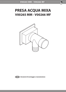
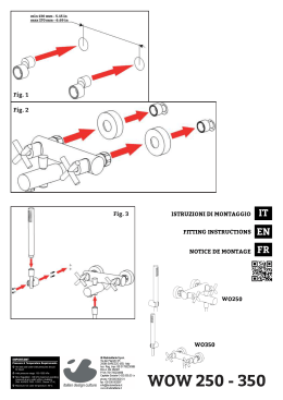
INSTALLATION AND USER’S MANUAL
SALIENT / SALIENT SLOW
Electromechanical actuators
for projecting up and over and sectional spring-loaded
comunello.com
ISTRUZIONI D’USO E DI INSTALLAZIONE
INSTALLATIONS-UND GEBRAUCHSANLEITUNG
INSTRUCIONS D’UTILISATION ET D’INSTALLATION
INSTRUCCIONES DE USO Y DE INSTALACION
ИНСТРУКЦИЯ ПО МОНТАЖУ
91300127 - Rev. 01 - 30.12.14
FIG. 1
FIG. 2
FIG. 3 A
FIG. 3 B
½H
H
100 mm
½H
FIG. 4
2
COMUNELLO ®Copyright 2013 - All right reserved
FIG. 5
FIG. 6 A
FIG. 6 B
~ 60 mm
~ 60 mm
FIG. 7
FIG. 8
COMUNELLO ®Copyright 2013 - All right reserved
3
FIG. 9
FIG. 10
FIG. 11
FIG. 12
FIG. 13
4
COMUNELLO ®Copyright 2013 - All right reserved
FIG. 14
FIG. 15
COMUNELLO ®Copyright 2013 - All right reserved
5
FIG. 16
FIG. 17
6
COMUNELLO ®Copyright 2013 - All right reserved
FIG. 18
1 2 3 4 5
MOT1 CLOSE
MOT1 COM
MOT1 OPEN
CN1
L N
OPEN
COMMON
(QUAD 230V 1M)
CLOSED
SALIENT + QUAD
END STOP OPEN
5
6
FCA
GND
END STOP CLOSED
FCC
COMMON
GND
LAMP+
FOTO+
LAMP
CN2
1
2
3
4
LAMP +24V
(SALIENT 230V)
1 2 3 4 5 6
MOT -
MOT +
LAMP -
LAMP +
BATT -
BATT +
CN1
CN2
5
6
7 8
9 10
CN3
(SALIENT 24V)
10 9 8 7 6 5 4 3 2 1
CN2
2° CH
1
2° CH
2
FOTO+
3
LAMP 24V 4W
4
+
(QUAD 230V HP)
1 2 3 4 5 6 7 8
CN1
(SALIENT 230V)
CN3
10 9 8 7 6 5 4 3 2 1
E1
+
+ 24 V
(QUAD 24V HP)
0V
MOT1 -
GND
M 1 ENC 1
END STOP CLOSED
MOT1 +
FC FA
END STOP OPEN
LAMP -
+
COMMON
LAMP +
E1
LAMP+
BATT -
GND
M 2 ENC 2
LAMP
BATT +
FC FA
F1
OPEN
5
GND
COMMON
MOT2 CLOSE
E1
CLOSED
MOT1 CLOSE
GND
M 1 ENC 1
END STOP OPEN
MOT2 COM
FC FA
END STOP CLOSED
MOT1 COM
+
COMMON
MOT2 OPEN
E1
LAMP+
LAMP 230V
GND
M 2 ENC 2
LAMP
MOT1 OPEN
FC FA
LAMP 230V
L N
+ 24 V
4
0V
F1
2 3
END STOP OPEN
(QUAD 24V 1M)
1
END STOP CLOSED
5
FCA
CN1
COMMON
FCC
GND
LAMP+
GND
LAMP
1
2
3
4
FOTO +
(SALIENT 24V)
FIG. 19
Vedere manuale di riferimento della centralina
See electronic control unit instructions
SALIENT
COMUNELLO ®Copyright 2013 - All right reserved
7
FIG. 20
2 SALIENT
CN1
MOT1 COM
MOT1 CLOSE
L N
MOT1 OPEN
1 2 3 4 5
M
CN2
OPEN
COMMON
CLOSED
GND
END STOP OPEN (N.C.)
END STOP OPEN
5
6
FCA
END STOP CLOSED
FCC
COMMON
GND
LAMP+
FOTO+
INTERNAL MOTOR 230V 50HZ
LAMP
1
2
3
4
LAMP +24V
END STOP CLOSE (N.C.)
(SALIENT 230V - WITH MAIN BOARD)
L N
10 9 8 7 6 5 4 3 2 1
CN3
FC FA
GND E1
+
FC FA GND
E1
CN2
2° CH
+
M 2 ENC 2 M 1 ENC 1
2° CH
FOTO+
OPEN
COMMON
CLOSED
END STOP OPEN
M
END STOP CLOSED
COMMON
GND
LAMP+
LAMP 24V 4W
1
2
3
4
5
LAMP
LAMP 230V
MOT1 OPEN
MOT1 COM
MOT1 CLOSE
MOT2 OPEN
MOT2 COM
MOT2 CLOSE
F1
1 2 3 4 5 6 7 8 9 10
LAMP 230V
CN1
(SALIENT 230V)
(N.C.) END STOP CLOSE MOTOR
INTERNAL MOTOR 230V 50HZ
(N.C.) END STOP OPEN MOTOR
(SALIENT 230V - WITH MAIN BOARD)
(SALIENT 230V)
CN1
1 2 3 4 5 6 7 8
CN3
10 9 8 7 6 5 4 3 2 1
FC FA
+
FC FA
GND E1
+
BATT +
BATT LAMP +
LAMP MOT1 +
MOT1 MOT2 +
MOT2 -
+ 24 V
COMUNELLO ®Copyright 2013 - All right reserved
0V
8
END STOP CLOSED
(SALIENT 24V - WITH MAIN BOARD)
(N.C.) END STOP OPEN MOTOR
END STOP OPEN
INTERNAL MOTOR 24V
COMMON
M
LAMP+
(N.C.) END STOP CLOSE MOTOR
LAMP
F1
GND E1
M 2 ENC 2 M 1 ENC 1
(SALIENT 24V)
FIG. 21
2 SALIENT + QUAD
L N
CN3
10 9 8 7 6 5 4 3 2 1
FC FA
GND E1
+
FC FA GND
E1
CN2
2° CH
FOTO+
OPEN
COMMON
CLOSED
END STOP OPEN
END STOP CLOSED
(SALIENT 230V)
COMMON
LAMP+
LAMP
OPEN
COMMON
CLOSED
END STOP OPEN
END STOP CLOSED
(QUAD 230V HP)
COMMON
GND
LAMP+
LAMP 24V 4W
LAMP
1
2
3
4
5
2° CH
+
M 2 ENC 2 M 1 ENC 1
LAMP 230V
F1
1 2 3 4 5 6 7 8 9 10
LAMP 230V
MOT1 OPEN
MOT1 COM
MOT1 CLOSE
MOT2 OPEN
MOT2 COM
MOT2 CLOSE
CN1
(SALIENT 230V)
1 2 3 4 5
MOT1 COM
MOT1 CLOSE
MOT1 OPEN
CN1
L N
OPEN
COMMON
CLOSED
END STOP OPEN
END STOP CLOSED
COMMON
LAMP+
LAMP
OPEN
(SALIENT 230V)
10 9 8 7 6 5 4 3 2 1
GND E1
+
FC FA
GND E1
+
+ 24 V
0V
END STOP CLOSED
END STOP OPEN
COMMON
(SALIENT 24V)
LAMP+
LAMP
+ 24 V
0V
END STOP CLOSED
END STOP OPEN
COMMON
(QUAD 24V HP)
FC FA
M 2 ENC 2 M 1 ENC 1
LAMP+
BATT +
BATT LAMP +
LAMP MOT1 +
MOT1 MOT2 +
MOT2 -
CN3
LAMP
F1
COMMON
(SALIENT 230V)
1 2 3 4 5 6 7 8
CN1
CLOSED
(QUAD 230V 1M)
END STOP OPEN
5
6
FCA
GND
END STOP CLOSED
FCC
COMMON
GND
LAMP+
FOTO+
LAMP
CN2
1
2
3
4
LAMP +24V
(SALIENT 24V)
COMUNELLO ®Copyright 2013 - All right reserved
9
FIG. 22
TABELLA CONNESSIONI CAVI AG01 - WIRES CONNECTION TABLE AG01
OVERHEAD DOOR (CU 24V 1M)
ID
Description
1
3
5A
5B
4
2
Main power supply
Flashing light
Photocell TX
Photocell RX
Key selector
Antenna
10
Cable type
FROR CEI 20-22
CEI EN 50267-2-1
Lenght (1m to 10m)
Lenght (10m to 20m)
2x1,0mm2
2x0,5mm2
2x0,5mm2
4x0,5mm2
3x0,5mm2
2x1,5mm2
2x1,0mm2
2x1,0mm2
4x1,0mm2
3x1,0mm2
RG58
COMUNELLO ®Copyright 2013 - All right reserved
max 20m
620
FIG. 23
197
140
140
COMUNELLO ®Copyright 2013 - All right reserved
11
ISTRUZIONI D’USO E DI INSTALLAZIONE
SALIENT
DICHIARAZIONE DI CONFORMITÁ CE
Il sottoscritto, sig. COMUNELLO LUCA rappresentante il seguente costruttore
F.lli COMUNELLO spa
Via Cassola 64, 36027 Rosà (VI) Italy
DICHIARA che l’apparecchiatura descritta in appresso:
Descrizione Modello Automazione elettromeccanica per portoni basculanti.
SALIENT
è conforme alle disposizioni legislative che traspongono le seguenti direttive:
• direttiva 2004/108 CE (Direttiva EMC)
• direttiva 2006/42/CE (Direttiva Macchine)
e che sono state applicate tutte le norme e/o specifiche tecniche di seguito indicate
EN61000-6-2 + EN61000-6-3
EN62233 :2008
EN301489-1 + EN301489-3 + EN300220-2
EN60335-2-103 :2003 + EN60335-1 :2002
EN13241-1 + EN12445 + EN12453
ed emendamenti successivi
Ultime due cifre dell’anno in cui è affissa la marcatura CE 14
Rosà (VI) – Italia
01-09-2014
Inoltre dichiara che non è consentito mettere in servizio il macchinario fino a che la macchina in cui sarà incorporata o di cui diverrà
componente sia stata identificata e ne sia stata dichiarata la conformità alle condizioni della Direttiva 2006/42/CE e alla legislazione
nazionale che la traspone.
Dr. LUCA COMUNELLO
Legale rappresentante della FRATELLI COMUNELLO s.p.a.
Fratelli Comunello S.p.A.
Azienda con Sistema Gestione Qualità certificato
UNI EN ISO 9001:2008.
(Certificato n° 50 100 11235 Rev. 01)
12
COMUNELLO ®Copyright 2013 - All right reserved
1
AVVERTENZE GENERALI
1.1 Avvertenze per la sicurezza
1.2 Avvertenze per l’installazione
1.3 Avvertenze per l’uso
2
MODELLI E DESCRIZIONE PRODOTTO
2.1 Descrizione
2.2
Installazione tipica
3
CARATTERISTICHE TECNICHE DEL PRODOTTO
4
INSTALLAZIONE
4.1 Verifiche preliminari
4.2 Limiti d’impiego
4.3 Lavori di predisposizione all’installazione
4.4 Installazione del motoriduttore mod. SALIENT
4.4.1Installazione
4.4.2 Installazione finecorsa
4.4.3 Sblocco manuale del motoriduttore
5
PREDISPOSIZIONE AI COLLEGAMENTI ELETTRICI
6COLLAUDO
7
MANUTENZIONE DEL PRODOTTO
8RICAMBI
9
SMALTIMENTO DEL PRODOTTO
10GARANZIA
1 AVVERTENZE
1.1 AVVERTENZE PER LA SICUREZZA
Il presente manuale di installazione è rivolto esclusivamente
a personale professionalmente competente. È necessario
leggere tutte le istruzioni prima di procedere all’installazione.
Tutto quello che non è espressamente previsto in queste
istruzioni non è permesso; usi non previsti potrebbero
essere fonte di danni al prodotto e mettere in pericolo
persone e cose. Il costruttore declina qualsiasi responsabilità
dall’inosservanza della buona tecnica nella costruzione dei
cancelli, nonché delle deformazioni che potrebbero verificarsi
durante l’uso. Conservare questo manuale anche per utilizzi
futuri. La progettazione, la fabbricazione dei dispositivi che
compongono SALIENT ed il presente manuale rispettano
pienamente la norma vigente. Considerando le situazioni
di rischio che possono verificarsi durante l’installazione
e l’uso di SALIENT e necessario che anche l’installazione
avvenga nel pieno rispetto di leggi, norme e regolamenti; in
particolare:
durante l’installazione evitare che liquidi possano penetrare
all’interno della centrale e di altri dispositivi aperti.
• Qualora sostanze liquide siano penetrate all’interno dei
dispositivi dell’automatismo, scollegare immediatamente
l’alimentazione elettrica e rivolgersi al servizio di assistenza;
l’uso di SALIENT in tali situazioni può causare situazioni di
pericolo.
• Non tenere qualsiasi componente di SALIENT vicino a
fonti di calore né esporlo a fiamme; tali azioni possono
danneggiarlo ed essere causa di malfunzionamenti,
incendio o situazioni di pericolo.
• Nel caso di lunghi periodi di inutilizzo, per evitare il rischio
di perdite di sostanze nocive dalla batteria opzionale è
preferibile estrarla e custodirla in luogo asciutto.
• Collegare la centrale solo ad una linea di alimentazione
elettrica dotata
di messa a terra di sicurezza.
• Tutte le operazioni che richiedono l’apertura dei gusci di
SALIENT devono avvenire con la centrale di comando
scollegata e dall’alimentazione elettrica; se il dispositivo
di sconnessione non è a vista apporvi un cartello:
“ATTENZIONE MANUTENZIONE IN CORSO”.
• Qualora si verifichino interventi di interruttori automatici o
di fusibili, prima di ripristinarli è necessario individuare ed
eliminare il guasto.
•Nel caso di guasto non risolvibile facendo uso delle
informazioni riportate nel presente manuale, interpellare il
servizio di assistenza.
2 MODELLI E DESCRIZIONE PRODOTTO
2.1 DESCRIZIONE
SALIENT è un attuatore elettromeccanico per portoni basculanti ad uso residenziale con
centrale integrata che consente di muovere il portone mediante pulsante, radiocomando
e, quando necessario, manualmente grazie all’apposito sblocco manuale in dotazione.
2.2 INSTALLAZIONE TIPICA
C
1.2 AVVERTENZE PER L’INSTALLAZIONE
•Prima di iniziare l’installazione verificare la necessità di
ulteriori dispositivi e materiali che possono servire a
completare l’automazione con SALIENT in base alla
specifica situazione d’impiego.
• L’automatismo non deve essere utilizzato prima di aver
messo in sicurezza la porta.
• Il materiale dell’imballaggio deve essere smaltito nel pieno
rispetto della normativa locale.
1.3 AVVERTENZE PER L’USO
•Non eseguire modifiche su nessuna parte se non
previste nel presente manuale. Operazioni di questo tipo
possono solo causare malfunzionamento. Il costruttore
declina ogni responsabilità per danni derivati da prodotti
modificati.
•Evitare che le parti dell’automatismo possano venir
immerse in acqua o in altre sostanze liquide. Anche
A
D
B
LEGENDA
AMOTORIDUTTORE
BFOTOCELLULE
CLAMPEGGIANTE
D SELETTORE A CHIAVE
3 CARATTERISTICHE TECNICHE
COMUNELLO ®Copyright 2013 - All right reserved
13
ITALIANO
INDICE
SALIENT
Alimentazione (se centrale)
Alimentazione motore
Potenza assorbita
Assorbimento
Coppia
Intermittenza di lavoro
Grado di protezione
Classe di isolamento
Temp. di funzionamento
Velocità
Peso
24
150 W
6,5 A
330 Nm
Uso intensivo
SALIENT SLOW
230 ~ 50Hz
230 ~
280 W
1,2 A
440 Nm
40%
230 ~
280 W
1,2 A
440 Nm
40%
IP24D
II
1 messa a terra
da -20°C a + 50°C
1,7 rpm
1,2 rpm
11,2 Kg
11,4 Kg
11,4 Kg
4 INSTALLAZIONE
4.1 VERIFICHE PRELIMINARI
Per un corretto funzionamento dell’automazione assicurarsi che:
• Tutti gli accessori siano adeguatamente dimensionati ed opportunamente manutentati.
• La porta, se lasciata libera in ogni posizione, non si muova da sola.
Il portone deve essere controbilanciato da molle o contrappesi.
• Che nella corsa del portone, sia in chiusura che in apertura, non ci siano punti di
maggiore attrito.
4.2 LIMITI D’IMPIEGO
Prima di eseguire l’installazione del motoriduttore, verificare che i suoi dati rientrino nei limiti
d’impiego nel capitolo 3 “Caratteristiche tecniche del prodotto”.
4.3 LAVORI DI PREDISPOSIZIONE ALL’INSTALLAZIONE
•
•
•
•
Estrarre l’attuatore dalla scatola.
Sbloccare il motore come illustrato nel paragrafo 4.4.3.
Togliere prima la maniglia e poi il carter come illustrato in FIG. 1.
ATTENZIONE! l’attuatore viene fornito non assemblato.
• Chiudere il coprischeda con le 4 viti.
• Collegare il filo giallo/verde (messa a terra) al capocorda ad occhiello già
avvitato al lato del foro passaggio cavi. (per i modelli di classe I).
6 COLLAUDO
Ogni singolo elemento dell’automatismo, ad esempio bordi sensibili, fotocellule, arresto di
emergenza, ecc. richiede una specifica fase di collaudo; per questi dispositivi si dovranno
eseguire le procedure riportate nei rispettivi manuali istruzioni. Per il collaudo di SALIENT
eseguire la seguente sequenza di operazioni:
• Verificare che sia stato rispettato rigorosamente tutto quanto previsto nel presente
manuale ed in particolare nel capitolo 1 “Avvertenze”.
• Utilizzando i dispositivi di comando o arresto previsti (selettore a chiave, pulsanti di
comando o trasmettitori radio), effettuare delle prove di apertura, chiusura ed arresto
del cancello e verificare che il comportamento corrisponda a quanto previsto.
• Verificare uno ad uno il corretto funzionamento di tutti i dispositivi di sicurezza presenti
nell’impianto (fotocellule, bordi sensibili, arresto di emergenza, ecc.).
7 MANUTENZIONE DEL PRODOTTO
La manutenzione deve essere effettuata regolarmente da parte di personale qualificato
secondo quanto previsto dalle leggi e normative vigenti. Per SALIENT è necessaria una
manutenzione programmata al massimo entro 6 mesi o 10.000 manovre dalla precedente
manutenzione.
• Scollegare qualsiasi fonte di alimentazione dal motore.
• Verificare e sotituire tutte le parti di movimento usurate.
• Verificare lo stato di deterioramento di tutte le parti dell’automazione.
8 RICAMBI
È possibile acquistare dei particolari di ricambio, in caso di tale necessità contattare
l’assistenza tecnica.
4.4 INSTALLAZIONE DEL MOTORIDUTTORE MOD. SALIENT
9SMALTIMENTO
4.4.1 INSTALLAZIONE:
• Fissare la piastra base al portone (FIG. 2) rispettando le quote nelle rispettive figure 3A,
3B, (basculante debordante). Basculante non debordante. Orientare la piastra come
in FIG. 2.
• Fissare il motore alla piastra mediante le viti e dadi in dotazione FIG. 4.
• Fissare le staffe di supporto laterale in asse con l’albero scanalato come illustrato in
FIG. 5.
• Fissare le staffe laterali per bracci come illustrato in FIG. 6A.
• Considerare le quote indicative della FIG. 6B.
• Fissare l’asta telescopica come illustrato in FIG. 7
• Tagliare il tubo di trasmissione a misura e forarlo come illustrato in FIG. 8.
• Assemblare il tubo come illustrato in FIG. 9.
• Nel caso di utilizzo di 2 attuatori laterali utilizzare l’asta telescopica apposita come
illustrato in FIG. 10.
• Nel caso sia necessario, utilizzare l’asta curva come illustrato nella FIG. 11.
Al termine della vita dell’automazione, assicuratevi che lo smantellamento sia eseguito da
personale qualificato e che i materiali vengano riciclati o smaltiti secondo le norme valide
a livello locale.
4.4.2 INSTALLAZIONE FINECORSA
Il finecorsa è di tipo elettronico. Per la regolazione procedere come segue:
• Portare in posizione di chiusura il portone FIG. 12.
• Ruotare la camma destra fino a far intervenire lo switch FIG. 13.
• Portare il cancello in posizione di completa apertura FIG. 14.
• Ruotare la camma sinistra fino a far intervenire lo switch FIG. 15.
4.4.3 SBLOCCO MANUALE
Per sbloccare il motore e consentire un movimento manuale del portone ruotare la
maniglia in senso antiorario di 180° FIG. 17.
5 PREDISPOSIZIONE AI COLLEGAMENTI
ELETTRICI
ATTENZIONE! Per il collegamento alla rete, utilizzare cavo multipolare
previsto da normativa vigente come da manuale della centrale.
• Svitare le 4 viti del coprischeda (FIG. 16).
• Aprire attentamente e scollegare il connettore della scheda led dalla scheda
elettronica.
• Rimuovere il coprischeda.
• Effettuare i collegamenti come illustrato nelle istruzioni delle relative centraline
elettroniche.
• Ricollegare il connettore della scheda led alla centralina elettronica.
14
COMUNELLO ®Copyright 2013 - All right reserved
10 GARANZIA
Fratelli Comunello SpA garantisce, a condizione del rispetto delle speciche prestazionali
indicate nei manuali di istruzione dei prodotti, il corretto funzionamento degli attuatori per
24 mesi dalla data di fabbricazione. Fratelli Comunello S.p.a. garantisce in via esclusiva,
e quindi con esclusione di domande risarcitorie formulate per equivalente, la riparazione
o sostituzione gratuita delle parti difettose che verranno riconosciute tali, secondo
l’insindacabile giudizio tecnico del personale di Fratelli Comunello SpA. Il materiale in
garanzia inviato alla sede della Fratelli Comunello SpA, dovrà essere spedito in porto
franco e verrà quindi rispedito in porto assegnato. Il materiale ritenuto difettoso ed inviato a
Fratelli Comunello S.p.a. rimarrà di proprietà di quest’ultima società.
- Il costo di manodopera necessario per le riparazioni e sostituzioni eseguite rimane a
carico dell’acquirente. Non viene riconosciuto alcun indennizzo per il periodo d’inoperatività
dell’impianto. L’intervento non prolunga la durata della garanzia. A pena di decadenza,
l’acquirente deve denunciare gli eventuali vizi e difetti dei prodotti, entro il termine di 8 (otto)
giorni da calcolarsi rispettivamente dalla data di scoperta dei vizi o dalla data di consegna
della merce. La denuncia dovrà essere fatta esclusivamente per iscritto. La garanzia non
comprende: Avarie o danni causati dal trasporto; avarie o danni causati da vizi dell’impianto
elettrico presente presso l’acquirente il prodotto e/o da trascuratezza, negligenza,
inadeguatezza, uso anomalo di tale impianto; avarie o danni dovuti a manomissioni
poste in essere da parte di personale non autorizzato o conseguenti allo scorretto uso/
installazione (a questo proposito, si consiglia una manutenzione del sistema almeno ogni
sei mesi) o all’impiego di pezzi di ricambio non originali; difetti causati da agenti chimici e/o
fenomeni atmosferici.
La garanzia non comprende il costo per materiale di consumo né quello per vizi presunti
o veriche di comodo.
Caratteristiche dei prodotti
I prodotti realizzati da Fratelli Comunello SpA sono soggetti a continue innovazioni e
miglioramenti; pertanto, le caratteristiche costruttive e l’immagine degli stessi, potranno
subire variazioni anche senza preavviso.
Foro competente
Poiché il contratto viene perfezionato mediante Conferma d’Ordine compilata in Rosà, in
caso di controversia legale di qualsiasi natura è applicabile il diritto italiano ed è competente
il Foro di Vicenza (VI).
INSTALLATION AND USER’S MANUAL
SALIENT / SALIENT SLOW
EC DECLARATION OF COMFORMITY:
The undersigned Mr. Luca Comunello, representing the following manufacturer,
ENGLISH
Fratelli COMUNELLO Spa
Via Cassola 64, 36027 Rosà (VI) – Italy
DECLARES that the equipment described below:
Description: Model: Electromechanical actuators for projecting up and over and sectional spring-loaded.
SALIENT
Is in compliance with the provisions set down in the following directives:
• 2004/108 EC Directive (EMC Directive)
• 2006/42/EC Directive (Machinery Directive)
and that all the rules and/or technical specifications shown below have been applied:
EN61000-6-2 + EN61000-6-3
EN62233 :2008
EN301489-1 + EN301489-3 + EN300220-2
EN60335-2-103 :2003 + EN60335-1 :2002
EN13241-1 + EN12445 + EN12453
and the following amendments.
Last two digits of the year in which the EC marking has been affixed
14
Rosà (VI) – Italia
01-09-2014
and he also declares that it is not allowed to commission the device until the machinery where it will be incorporated or whose it will
become a component will have been identified and will have been declared in compliance with the conditions of the 2006/42 EC Directive
and with the national legislation that transpose it.
Mr. Luca Comunello
Fratelli Comunello Legal Representative
Fratelli Comunello S.p.A.
Company with certified Quality Management System
UNI EN ISO 9001:2008.
(Certificate n° 50 100 11235 Rev. 01)
COMUNELLO ®Copyright 2013 - All right reserved
15
CONTENTS
1
GENERAL PRESCRIPTIONS
1.1 Safety prescriptions
1.2 Installation prescriptions
1.3 Operating prescriptions
2
MODELS AND PRODUCTS DESCRIPTION
2.1 Description
2.2
Typical installation
3
PRODUCT TECHNICAL SPECIFICATIONS
4
INSTALLATION
4.1 Preliminary checks
4.2 Operating limits
4.3 Preparatory work for installation
4.4 Installing the SALIENT operator
4.4.1Installation
4.4.2 Installation of limit stops and switches
4.4.3 Operator manual release
5
PREPARATION FOR ELECTRICAL CONNECTIONS
6TESTING
7
PRODUCT MAINTENANCE
8
SPARE PARTS
9
DISPOSAL OF THE PRODUCT
10WARRANTY
1 PRESCRIPTIONS
1.1 SAFETY PRESCRIPTIONS
This installation manual is addressed exclusively to
professionally skilled personnel.
Read all the instructions carefully before starting the
installation procedures. Any operations that are not
expressly set down in these instructions are to be
considered prohibited; improper use may result in
damage to the product and place persons and property
at risk.
The manufacturer declines all liability for failure to observe
best practices in gate construction and for any possible
deformation that may occur during use of the product.
Store this manual in a safe place for future reference.
The design and construction of the devices of which
model SALIENT is composed and this manual are in full
compliance with statutory legislation.
In consideration of potential hazards that may arise
during the installation and use of SALIENT, the installation
procedures must be carried out in full compliance with
the applicable laws, standards and regulations; namely:
malfunctions. The manufacturer declines all liability for
damage caused by unauthorized modifications.
•The parts of the automation system must never
be immersed in water or other liquids. During the
installation procedures ensure that no liquids penetrate
inside the control unit or other open devices.
• If liquids penetrate any parts of the automation system
disconnect the electrical power supply immediately
and consult Comunello technical service; the use of
SALIENT in such conditions may give rise to potentially
hazardous situations.
•Keep all parts of SALIENT away from heat sources
and open flames; exposure to heat or flames may
damage the devices and cause faults, fire, or
hazardous situations.
• When the equipment remains unused for a long time,
remove the optional battery and store it in a dry place
to avoid the risk of leakage of harmful substances.
•Connect the control unit exclusively to an electric
power supply line equipped with an efficient protective
earth conductor.
•Any operations that require the SALIENT operator
housing to be opened must be performed with
the control unit and the electrical power supply
disconnected; if the disconnect device is not clearly
visible from where you are working, attach a warning
notice to the effect: “WARNING - MAINTENANCE IN
PROGRESS”.
• In the case of tripping of circuit breakers or blowing of
fuses, find the fault and remedy it before resetting the
circuit breaker or changing the fuse.
• If the fault cannot be remedied using the information
given in this manual, consult technical service.
2 MODELS AND PRODUCTS DESCRIPTION
2.1 DESCRIPTION
SALIENT is an electromechanical operator for up-and-over doors in residential
settings, with built-in control unit that allows the door to be operated from a
pushbutton, remote, and whenever necessary, manually using the specific release
provided.
2.2 TYPICAL INSTALLATION
1.2 INSTALLATION PRESCRIPTIONS
• Before starting the installation procedures make sure
you have any additional devices and materials that may
be required to complete the automation system with
SALIENT in consideration of the specific application.
• The door opener must not be used until the door has
been made safe.
•Dispose of packaging materials in compliance with
local regulations.
C
A
D
B
1.3 OPERATING PRESCRIPTIONS
•No modifications can be made to any part of the
product unless specified in this manual. Unauthorized
modification of the product is likely to lead to
KEY
16
COMUNELLO ®Copyright 2013 - All right reserved
A OPERATOR WITH BUILT-IN CONTROL UNIT
BPHOTOCELLS
C FLASHING LIGHT
D KEY SELECTOR SWITCH
•
•
•
•
•
•
•
3 TECHNICAL SPECIFICATIONS
SALIENT
24
150 W
6,5 A
330 Nm
Intensive
SALIENT SLOW
230 ~ 50Hz
230 ~
280 W
1,2 A
440 Nm
40%
230 ~
280 W
1,2 A
440 Nm
40%
IP24D
II
1 (EARTH)
from -20°C to + 50°C
1,7 rpm
1,2 rpm
11,2 Kg
11,4 Kg
11,4 Kg
4 INSTALLATION
4.1 PRELIMINARY CHECKS
For correct operation of the automation system, make sure:
• all the accessories are suitably sized and properly maintained.
• when released in any position, the door does not move autonomously. The
door must be balanced by springs or counterweights.
• there are no points of friction throughout the entire opening or closing travel of
the door.
4.2 OPERATING LIMITS
6 COLLAUDO
Each part of the automation system, e.g. safety edges, photocells, emergency
stop, etc. must be tested; follow the procedures shown in the instruction manuals
supplied with the devices in question. Perform the following sequence of operations
for testing of SALIENT:
• Check that all the prescriptions in this manual have been followed scrupulously,
with special attention to the matters set down in chapter 1 “General
Prescriptions”;
• Using the supplied control or stopping devices (key selector switch, control
pushbuttons or radio transmitters), perform gate opening, closing and stopping
tests and make sure the gate responds correctly to the various commands.
• Check operation of all the system safety devices (photocells, safety edges,
emergency stop, etc.) one by one.
7 PRODUCT MAINTENANCE
Maintenance must be carried out at regular intervals by qualified personnel in
compliance with the provisions of statutory legislation and the regulations in force.
SALIENT must be serviced at least once every 6 months or after 10,000 operating
cycles since the last service.
• Disconnect the operator from all power supplies.
• Check all the moving parts and replace any worn parts.
• Check all parts of the automation system for signs of deterioration.
Before installing the operator, check that its specifications are within the operating
limits shown in the chapter “Product Technical Specifications”.
8 SPARE PARTS
4.3 PREPARATORY WORK FOR INSTALLATION
Spare parts can be purchased by contacting technical service.
•
•
•
•
9 DISPOSAL OF THE PRODUCT
Remove the operator from the box.
Release the operator as described in heading 4.4.3
First remove the handle and then the case as shown in FIG. 1.
IMPORTANT: the operator is supplied disassembled.
4.4 INSTALLING THE OPERATOR
4.4.1 INSTALLATION:
• Secure the baseplate to the door (FIG. 2) complying with the dimensions given
in FIG. 3A and FIG. 3B, (projecting door, non-projecting door). Orient the plate
as shown in FIG. 2
• Fix the operator to the plate with the supplied nuts and bolts FIG. 4
• Fix the side support brackets so that they are in line with the splined drive shaft
as shown in FIG. 5
• Secure the side brackets for the arms as shown in FIG. 6A
Consider the guideline dimensions given in FIG. 6B.
• Fix the telescopic rod as shown in FIG. 7
• Cut the drive tube to length and drill it as shown in FIG. 8
• Assemble the tube as shown in FIG. 9
• When using 2 lateral operators use the specific telescopic rod as shown in
figure 10
• If necessary, fit the curved rod as shown in figure 11.
4.4.2 INSTALLATION OF LIMIT SWITCHES
Travel limiting is performed electronically. To adjust the electronic limit switches
proceed as follows:
• Bring the door to its closed position FIG. 12.
• Rotate the rightcam until causing the switch to trip FIG. 13.
• Bring the door to its fully open position FIG. 14.
• Rotate the left cam until causing the switch to trip FIG. 15.
4.4.3 MANUAL RELEASE
To release the operator so that the door can be opened and closed manually, turn
the handle counter-clockwise through 180° FIG. 17.
5 PREPARATION FOR ELECTRICAL
CONNECTIONS
WARNING! To connect to the network, use a multipolar cable provided by
regulations by the book’s unit.
At the end of its useful life the automation system must be dismantled by qualified
personnel and the materials must be recycled or disposed of in compliance with
the local legislation in force.
10 WARRANTY
fmndjklsvnbdsjkl Fratelli Comunello SpA provides a warranty for 24 months for
the correct functioning of the actuators from the date of manufacture, provided
that the performance specications indicated in the product instruction manuals
are respected. Free of charge repair and replacement of components that are
found to be faulty according to the indisputable judgment of the company’s
technical staff shall be guaranteed at the sole discretion of Fratelli Comunello Spa,
and so excluding any claim for damages made by others. Warranty material shall
be returned to Fratelli Comunello S.p.a. headquarters carriage paid and will then
be shipped to the customer carriage unpaid. The material found to be faulty and
returned to Fratelli Comunello S.p.a. shall remain property of the Seller. Any cost
resulting from any work needed to repair the defect or to replace the material shall
be charged to the Buyer. No compensation shall be allowed for the period of
device inactivity. Work under warranty does not prolong the warranty period. The
defect of the product shall be reported by the Buyer within 8 (eight) days from its
discovery or from the date of delivery of the goods, under penalty of invalidation of
the warranty. Such claim shall be notied in writing.
Warranty does not cover:
Any product defect or damage that may have been incurred during transport;
any defect or damage arising from any fault and/or from neglect, inadequacy
and misuse of the electrical wiring in the Buyer’s property; any defect or damage
caused by any repairs carried out by non authorised personnel or by incorrect use/
installation (with reference to this, system maintenance is recommended every 6
months) or if not original spare parts are used; any defect caused by chemicals
or atmospheric conditions. The warranty does not cover any cost neither for
consumable materials nor for alleged defects or convenient surveys.
Product Features Fratelli Comunello SpA products are subjected to continue
changes and improvements; their technical features and image may therefore
change without previous notice.
Competent court
Since the contract of sale is conrmed by an Order Conrmation drawn up in Rosà,
any such dispute shall be settled by the laws of Italy and by the court of Vicenza (VI).
COMUNELLO ®Copyright 2013 - All right reserved
17
ENGLISH
Power supply
Operator power supply
Current input
Power consumption
Torque
Duty cycle
Protection rating
Insulation class
Working temperature
Speed
Weight
Unscrew the 4 screws of the electronic board cover (FIG. 16)
Open carefully and unplug the LED board connector from the electronic board
Remove the electronic board cover
Make the connections as shown in the figures 18-19-20-21
Plug the LED board connector back into the control unit
Close the electronic board cover and secure it with the 4 screws.
Connect the yellow/green wire (earth) to the terminal eye already present
alongside the cable inlet hole (for models of class I).
INSTALLATIONS-UND GEBRAUCHSANLEITUNG
SALIENT
CE-KONFORMITÄTSERKLÄRUNG
Der Unterzeichner, Herr COMUNELLO LUCA, der den folgenden Hersteller vertritt:
F.lli COMUNELLO spa
Via Cassola 64, 36027 Rosà (VI) Italy
RKLÄRT, dass die anbei beschriebene Ausrüstung:
Elektromechanische automatische Torantrieb.
SALIENT
Beschreibung Modell den Gesetzesbestimmungen entspricht, die folgende Richtlinien umsetzen:
• Richtlinie 2004/108/EG (EMV-Richtlinie)
• Richtlinie 2006/42/EG (Maschinenrichtlinie)
und dass alle folgenden Normen und/oder technischen Spezifikationen angewendet wurden:
EN61000-6-2 + EN61000-6-3
EN62233 :2008
EN301489-1 + EN301489-3 + EN300220-2
EN60335-2-103 :2003 + EN60335-1 :2002
EN13241-1 + EN12445 + EN12453
sowie ihre nachträglichen Änderungen.
Letzte zwei Ziffern des Jahres, in dem das CE-Zeichen angebracht wurde 14
Rosà (VI) – Italien
01-09-2014
Außerdem wird erklärt, dass es nicht erlaubt ist, die Automatisierung in Betrieb zu setzen, solange die Anlage, in die sie eingebaut wird
oder mit der sie zusammengebaut wird, identifiziert wurde und deren Konformität mit den Erfordernissen der Richtlinie 2006/42/EG und
der entsprechenden nationalen Gesetzgebung erklärt wurde.
Dr. LUCA COMUNELLO
Rechtsvertreter der Firma FRATELLI COMUNELLO s.p.a.
Fratelli Comunello S.p.A.
Unternehmen mit UNI EN ISO 9001:2008
zertifizierten Qualitätssystem
(Bescheinigung n° 50 100 11235 Rev. 01)
18
COMUNELLO ®Copyright 2013 - All right reserved
INHALTSVERZEICHNIS
1
ALLGEMEINE HINWEISE
1.1 Sicherheitshinweise
1.2 Installationshinweise
1.3 Gebrauchshinweise
2
MODELLE UND PRODUKTBESCHREIBUNGEN
2.1 Beschreibung
2.2
Typische Installation
3
TECHNISCHE EIGENSCHAFTEN DES PRODUKTS
4
INSTALLATION
4.1 Vorbereitende Überprüfungen
4.2 Einsatzgrenzen
4.3 Vorbereitungen vor der Installation
4.4 Installation des Getriebemotors Mod. SALIENT
4.4.1Installation
4.4.2 Installation des Endschalters
4.4.3 Manuelles Entriegeln des Getriebemotors
5
VORBEREITUNG AUF DIE ELEKTRISCHEN ANSCHLÜSSE
6PRÜFUNG
7
INSTANDHALTUNG DES PRODUKTS
8ERSATZTEILE
9
ENTSORGUNG DES PRODUKTS
10WARRANTY
1 HINWEISE
2 MODELLE UND PRODUKTBESCHREIBUNG
2.1 BESCHREIBUNG
SALIENT ist ein elektromechanischer Antrieb mit integrierter Steuerung für Schwingtore in
Wohnbereichen; er erlaubt die Bewegung der Tore anhand von Tastern, Funksteuerung
und notfalls manuell, dank der hierzu vorgesehenen manuellen Entriegelung.
2.2 TYPISCHE INSTALLATION
C
1.2 INSTALLATIONSHINWEISE
•Vor Beginn der Installation prüfen, ob zusätzliche
Vorrichtungen und Materialien notwendig sind, die je
nach der spezifischen Verwendung zur Komplettierung
der Automatisierung mit SALIENT dienen können.
• Der automatische Antrieb darf nicht verwendet werden,
solange die Sicherheitsmaßnahmen am Tor nicht
erfasst wurden
• Das Verpackungsmaterial ist unter voller Einhaltung der
örtlichen Vorschriften zu entsorgen.
1.3 GEBRAUCHSHINWEISE
•Es dürfen nirgendwo Änderungen durchgeführt
werden, sofern nicht in diesem Handbuch vorgesehen.
Arbeiten dieser Art können lediglich Betriebsstörungen
verursachen.
Der Hersteller übernimmt keine Verantwortung für
A
D
B
LEGENDE
A GETRIEBEMOTOR MIT INTEGRIERTER STEUERUNG
BFOTOZELLEN
CBLINKLEUCHTE
DSCHLÜSSELTASTER
COMUNELLO ®Copyright 2013 - All right reserved
19
DEUTSCH
1.1 SICHERHEITSHINWEISE
Dieses Installationshandbuch wendet sich ausschließlich
an professionell kompetentes Personal.
Alle Anleitungen sind vor der Installation durchzulesen.
Alle nicht ausdrücklich in dieser Anleitung enthaltenen
Vorgänge sind nicht erlaubt; nicht bestimmungsgemäße
Verwendungen könnten Produktschäden verursachen
und Personen und Gegenstände in Gefahr versetzen.
Der Hersteller übernimmt keine Verantwortung für die
Nichteinhaltung der Regeln der Technik bei der Fertigung
der Tore, sowie für Verformungen, die sich beim Gebrauch
ereignen könnten. Dieses Handbuch ist auch für
zukünftige Benutzungen aufzubewahren. Das Projekt, die
Fertigung der zu SALIENT gehörenden Vorrichtungen und
dieses Handbuch erfüllen in vollem Ausmaß die geltenden
Vorschriften.
Unter Berücksichtigung der Risikosituationen, die sich
während der Installation und dem Gebrauch von SALIENT
ereignen können, muss auch die Installation unter voller
Einhaltung der Gesetze, Vorschriften und Regeln erfolgen;
insbesondere:
Schäden, die von veränderten Produkten herführen.
• Es ist zu vermeiden, dass Teile des Antriebssystems in
Wasser oder andere flüssige Stoffe tauchen können.
Auch während der Installation ist zu vermeiden, dass
Flüssigkeiten in die Steuerung und andere offenen
Vorrichtungen eindringen können.
• Falls flüssige Stoffe in die Vorrichtungen der Automatik
eingedrungen sind, ist unverzüglich die Stromversorgung
abzutrennen und den Kundendienst von Comunello
zu Rate zu ziehen; eine Verwendung von SALIENT in
diesem Zustand kann Gefahrsituationen verursachen.
• Die Bestandteile von SALIENT dürfen keinen Hitzequellen
oder Flammen ausgesetzt werden; sie könnten
dadurch beschädigt werden und Betriebsstörungen,
Brände oder Gefahrsituationen verursachen.
•Bei längerem Stillstand sollte der eventuelle Akku
entfernt und an einem trockenen Ort aufbewahrt
werden, um das Risiko des Austretens schädlicher
Stoffe zu vermeiden.
•Die Steuerung darf nur an eine Stromleitung mit
Schutzerdung angeschlossen werden.
•Vor allen Vorgängen, die eine Öffnung der SALIENTGehäuse verlangen, muss die Steuerung erst von
der Stromversorgung abgetrennt werden; falls die
Abschaltvorrichtung nicht sichtbar ist, ist ein Schild
anzubringen: „ACHTUNG! IM WARTUNGSZUSTAND”.
• Falls Selbstabschalter oder Sicherungen ansprechen,
ist vor ihrer Rückstellung bzw. Instandsetzung der
Defekt zu erkennen und zu beseitigen.
• Im Falle von Defekten, die mit den in diesem Handbuch
enthaltenen Information nicht behoben werden können,
ist mit dem Kundendienst von Kontakt aufzunehmen.
TECHNISCHE EIGENSCHAFTEN
SALIENT
Speisung
Motorspeisung
Leistungsaufnahme
Aufnahme
Drehmoment
Einschaltdauer
Schutzgrad
Isolationsklasse
Betriebstemperatur
Laufzeit
Gewicht
SALIENT SLOW
230 ~ 50Hz
230 ~
24
150 W
6,5 A
330 Nm
Intensiv
230 ~
280 W
1,2 A
440 Nm
40%
280 W
1,2 A
440 Nm
40%
IP 24 D
II
1 (Erdung)
von -20°C bis + 50°C
1,7 rpm
11,2 Kg
1,2 rpm
11,4 Kg
11,4 Kg
4 INSTALLATION
4.1 VORBEREITENDE ÜBERPRÜFUNGEN
Für einen korrekten Betrieb des Antriebssystems ist folgendes zu prüfen:
• Alle Zubehöre müssen in geeigneter Weise bemessen und ordnungsgemäß
gewartet sein.
• Das Tor darf sich wenn freigelassen in keiner Position von alleine bewegen. Das Tor
muss durch Federn oder Gegengewichte ausgeglichen sein.
• Sowohl beim Schließen als auch beim Öffnen darf es am Laufweg entlang keine
stärkeren Reibstellen geben.
4.2 EINSATZGRENZEN
Vor der Installation des Getriebemotors prüfen, dass seine Daten innerhalb der
Grenzwerte laut Kapitel „Technische Eigenschaften des Produkts“ liegen.
4.3 VORBEREITUNGEN VOR DER INSTALLATION
•
•
•
•
Den Antrieb aus der Schachtel nehmen.
Den Motor wie im Abs. 4.4.3 dargestellt entriegeln.
Wie in der ABB. 1 dargestellt, zuerst den Griff und dann das Gehäuse abnehmen.
ACHTUNG! Der Antrieb wird im unmontierten Zustand geliefert.
4.4 INSTALLATION DES GETRIEBEMOTORS
4.4.1 INSTALLATION:
• Die Grundplatte am Tor befestigen (ABB. 2); dabei die Maße der ABB. 3A, ABB.
3B beachten (ausschwingendes Schwingtor, nicht ausschwingendes Schwingtor).
Die Platte gemäß ABB. 2 orientieren.
• Den Motor mit den beigestellten Schrauben und Muttern an der Platte befestigen,
ABB.4
• Die seitlichen Haltebügel gemäß ABB. 5 achsgerecht mit der Keilwelle befestigen
• Die seitlichen Armhaltebügel gemäß ABB. 6A befestigen
Die Richtmaße der ABB 6B berücksichtigen.
• Die Teleskopstange gemäß ABB. 7 befestigen
• Das Übertragungsrohr gemäß ABB. 8 zuschneiden und bohren
• Das Rohr gemäß ABB. 9 zusammenbauen
• Bei Verwendung von 2 seitlichen Antrieben ist die Teleskopstange wie in der ABB.
10 gezeigt zu verwenden
• Falls notwendig, die Stange wie in der ABB. 11 gezeigt gebogen verwenden.
4.4.2 INSTALLATION DES ENDSCHALTERS
Der Endschalter funktioniert elektronisch. Zur Einstellung folgende Schritte ausführen:
• Das Tor schließen, siehe ABB.12
• Den Recht Nocken drehen, bis der Switch ausgelöst wird, ABB. 13
• Das Tor komplett öffnen, ABB. 14
• Den links Nocken drehen, bis der Switch ausgelöst wird, ABB. 15
4.4.3 MANUELLES ENTRIEGELN
Um den Motor zu entriegeln und eine manuelle Torbewegung zu ermöglichen, den Griff
um 180° im Gegenuhrzeigersinn drehen, ABB. 17.
5
VORBEREITUNG
ANSCHLÜSSE
AUF
DIE
ELEKTRISCHEN
ACHTUNG! Um mit dem Netzwerk verbinden, ein mehrpoliges Kabel durch
Vorschriften des Buches Einheit vorgesehen.
• Die 4 Schrauben des Kartendeckels losschrauben (ABB. 16)
• Vorsichtig öffnen und den Verbinder der Led-Karte von der Elektronikkarte
abtrennen
• Den Kartendeckel entfernen
20
COMUNELLO ®Copyright 2013 - All right reserved
• Die Anschlüsse gemäß Abb. 18-19-20-21 fertigen
• Den Verbinder der Led-Karte wieder an der elektronischen Steuerung anschließen
• Den Kartendeckel mit den 4 Schrauben schließen
• Den gelb-grünen Leiter (Erdung) an den bereits an der Seite der
Kabeldurchführung
angeschraubten
Ringkabelschuh
anschließen.
(Für
die
Modelle
der
Klasse
I).
6 PRÜFUNG
Jedes einzelne Element des Antriebssystems, z.B. die Sicherheitsleisten, Fotozellen,
Notabschalter, usw., verlangt eine spezifische Prüfphase; an allen diesen Vorrichtungen
sind die in den jeweiligen Anleitungshandbüchern enthaltenen Prozeduren
durchzuführen. Bei der Prüfung von SALIENT sind die folgenden Arbeitsschritte
erforderlich:
• Prüfen, dass alle in diesem Handbuch und besonders im Kapitel „1 Hinweise“
enthaltenen Vorgaben strikt eingehalten wurden;
• Unter Verwendung der Bedienungs- oder Ausschaltvorrichtungen (Schlüsseltaster,
Bedienungstaster oder Funksender), AUF-STOP-ZU Versuche mit dem Tor
durchführen und das vorschriftsmäßige Verhalten prüfen.
•Alle Sicherheitsvorrichtungen der Anlage (Fotozellen, Sicherheitsleisten,
Notabschalter, usw.) einzeln nach ihrer korrekten Betriebsfähigkeit überprüfen.
7 INSTANDHALTUNG DES PRODUKTS
Qualifiziertes Personal muss regelmäßig die Instandhaltung nach den geltenden
Gesetzen und Normvorschriften durchführen. SALIENT verlangt eine programmierte
Instandhaltung nach maximal 6 Monaten oder 10.000 Manövern ab der letzten
Wartung.
• Alle Versorgungsquellen vom Motor abtrennen
• Alle Bewegungselemente überprüfen und abgenutzte Teile auswechseln
• Alle Bestandteile des Antriebssystems auf ihren Abnutzungszustand überprüfen.
8 ERSATZTEILE
Es besteht die Möglichkeit, Ersatzteile zu erwerben; notfalls ist hierzu mit dem
technischen Kundendienst von COMUNELLO Kontakt aufzunehmen.
9 ENTSORGUNG DES PRODUKTS
Nach Lebensende des Antriebssystems sicherstellen, dass die Abrüstung von
qualifiziertem Personal durchgeführt wird und die Materialien nach örtlich geltenden
Vorschriften rezykliert oder entsorgt werden.
10 WARRANTY
fmndjklsvnbdsjkl Fratelli Comunello SpA provides a warranty for 24 months for the
correct functioning of the actuators from the date of manufacture, provided that the
performance specications indicated in the product instruction manuals are respected.
Free of charge repair and replacement of components that are found to be faulty
according to the indisputable judgment of the company’s technical staff shall be
guaranteed at the sole discretion of Fratelli Comunello Spa, and so excluding any claim
for damages made by others. Warranty material shall be returned to Fratelli Comunello
S.p.a. headquarters carriage paid and will then be shipped to the customer carriage
unpaid. The material found to be faulty and returned to Fratelli Comunello S.p.a. shall
remain property of the Seller. Any cost resulting from any work needed to repair the
defect or to replace the material shall be charged to the Buyer. No compensation shall
be allowed for the period of device inactivity. Work under warranty does not prolong
the warranty period. The defect of the product shall be reported by the Buyer within 8
(eight) days from its discovery or from the date of delivery of the goods, under penalty
of invalidation of the warranty. Such claim shall be notied in writing.
Warranty does not cover:
Any product defect or damage that may have been incurred during transport; any
defect or damage arising from any fault and/or from neglect, inadequacy and misuse
of the electrical wiring in the Buyer’s property; any defect or damage caused by
any repairs carried out by non authorised personnel or by incorrect use/installation
(with reference to this, system maintenance is recommended every 6 months) or if
not original spare parts are used; any defect caused by chemicals or atmospheric
conditions. The warranty does not cover any cost neither for consumable materials nor
for alleged defects or convenient surveys.
Product Features Fratelli Comunello SpA products are subjected to continue changes
and improvements; their technical features and image may therefore change without
previous notice.
Competent court
Since the contract of sale is conrmed by an Order Conrmation drawn up in Rosà, any
such dispute shall be settled by the laws of Italy and by the court of Vicenza (VI).
INSTRUCIONS D’UTILISATION ET D’INSTALLATION
SALIENT
DÉCLARATION DE CONFORMITÉ CE
Le soussigné, M. COMUNELLO LUCA, représentant le suivant constructeur
F.lli COMUNELLO spa
Via Cassola 64, 36027 Rosà (VI) Italie
Déclare que l’appareil décrit ci-dessous:
Description
Automatisme électromécanique pour portails.
Modèle SALIENT
Est conforme aux dispositiones légales transposant les directives suivantes:
• Directive 2004/108 CE (Directive EMC)
• Directive 2006/42 CE (Directive Machines)
Et qui ont été soumis toutes les norms et /ou spécifications techniques ci-après indiquées:
EN61000-6-2 + EN61000-6-3
EN62233 :2008
EN301489-1 + EN301489-3 + EN30220-2
EN60335-2-103 :2003 + EN60335-1 :2002
EN13241-1 + EN12445 + EN12453
Et amendements ultérieurs
FRANÇAIS
Les deux derniers chiffres de l’année dans laquelle il a été apposé le marquage CE
14
Rosà (VI) – Italie
01-09-2014
Nous déclarons en outre que la machine ne pourra pas être mise en service avant identification et déclaration de conformité aux
conditions de la Directive 2006/42 CE et à la législation nationale la transposant de la machine à laquelle elle sera intégrée ou dont elle
deviendra partie intégrante.
Luca Comunello
Représentant légal de la société Fratelli Comunello
Fratelli Comunello S.p.A.
Enterprise avec Système de Management de la Qualité certifié
UNI EN ISO 9001:2008
(Certificat n° 50 100 11235 Rev. 01)
COMUNELLO ®Copyright 2013 - All right reserved
21
SOMMAIRE
1
AVERTISSEMENTS GÉNÉRAUX
1.1 Avertissements concernant la sécurité
1.2 Avertissements concernant l’installation
1.3 Avertissements concernant l’utilisation
2
MODÈLES ET DESCRIPTION PRODUITS
2.1 Description
2.2
Installation type
3
CARACTÉRISTIQUES TECHNIQUES DU PRODUIT
4
INSTALLATION
4.1 Contrôles préliminaires
4.2 Limites d’utilisation
4.3 Travaux préalables à l’installation
4.4 Installation de l’opérateur mod. SALIENT
4.4.1Installation
4.4.2 Installation fin de course
4.4.3 Débrayage manuel de l’opérateur
5
PRÉDISPOSITION AUX BRANCHEMENTS ÉLECTRIQUES
6ESSAI
7
ENTRETIEN
8
PIÈCES DÉTACHÉES
9ÉLIMINATION
10GARANTIE
1 AVERTISSEMENTS
1.1 AVERTISSEMENTS CONCERNANT LA
SÉCURITÉ
Ce manuel d’installation s’adresse exclusivement à un
personnel compétent.
Il est indispensable d’avoir lu toutes les instructions
avant de procéder à l’installation, Toutes les opérations
non expressément prévues dans ces instructions sont
interdites ; toute utilisation non prévue peut entraîner des
dommages matériels et des risques de blessures.
Le constructeur décline toute responsabilité en cas de
non-observation des règles de bonne technique dans
la construction des portails ou en cas de déformations
survenant durant l’utilisation. Conserver ce manuel pour
toute future consultation. La conception et la fabrication
des dispositifs composant SALIENT et ce manuel sont
rigoureusement conformes aux normes en vigueur.
Étant donné les situations de risques pouvant se présenter
durant l’installation et l’utilisation de SALIENT, l’installation
doit nécessairement être effectuée en stricte conformité
avec les lois, normes et réglementations ; en particulier:
•
Éviter toute immersion de composants de
l’automatisme dans l’eau ou dans d’autres liquides.
Durant l’installation, éviter également toute pénétration
de liquides à l’intérieur du coffret de commande et
d’autres dispositifs ouverts.
•En cas de pénétration d’un liquide à l’intérieur des
dispositifs de l’automatisme, sectionner immédiatement
l’alimentation électrique et s’adresser au service
d’assistance Comunello ; toute utilisation de SALIENT
dans une telle situation comporte des risques.
•Ne pas laisser les composants de SALIENT à
proximité de sources de chaleur et ne pas les exposer
à des flammes sous peine d’endommagement et de
dysfonctionnement, incendie ou situation de danger.
•En cas d’inutilisation prolongée, en vue d’éviter tout
risque de pertes de substances nocives de la batterie
en option, il est conseillé de retirer cette dernière et de
la conserver dans un endroit sec.
• Brancher uniquement le coffret de commande à une
ligne d’alimentation équipée d’une mise à la terre de
sécurité.
•Toutes les opérations exigeant l’ouverture du carter
de SALIENT doivent être effectuées avec le coffret de
commande débranché de l’alimentation électrique; si
le dispositif de déconnexion en est dépourvu, prévoir
un panneau: «ATTENTION ENTRETIEN EN COURS».
• En cas d’intervention d’interrupteurs automatiques ou
de fusibles, identifier et éliminer le problème avant de
les réarmer.
• En cas de panne ne pouvant être résolue au moyen
des informations fournies dans ce manuel, contacter le
service d’assistance COMUNELLO.
2 MODÈLES ET DESCRIPTION PRODUIT
2.1 DESCRIPTION
SALIENT est un opérateur électromécanique pour portails basculants à usage
résidentiel équipé d’une logique de commande intégrée permettant l’actionnement
du portail au moyen d’un bouton, d’une radiocommande et, si nécessaire, en mode
manuel grâce au débrayage manuel prévu de série.
2.2 2.2
INSTALLATION TYPE
1.2 AVERTISSEMENTS CONCERNANT
L’INSTALLATION
• Avant de procéder à l’installation, vérifier la nécessité
éventuelle d’autres dispositifs et matériels permettant
de compléter l’automatisme avec SALIENT en fonction
de l’utilisation prévue.
•Ne pas utiliser l’automatisme avant d’avoir placé le
portail en conditions de sécurité
•Éliminer le matériel d’emballage conformément aux
normes locales.
1.3 AVERTISSEMENTS CONCERNANT
L’UTILISATION
•
N’effectuer aucune modification sur quelque
composant que ce soit, sauf prévue dans ce manuel.
Ce type d’intervention est uniquement susceptible
d’entraîner des dysfonctionnements.
Le constructeur décline toute responsabilité en cas de
dommages entraînés par une modification du produit.
22
COMUNELLO ®Copyright 2013 - All right reserved
C
A
D
B
LÉGENDE
A OPÉRATEUR À LOGIQUE DE COMMANDE INTERNE
BPHOTOCELLULES
CCLIGNOTANT
D SÉLECTEUR À CLÉ
3 CARACTÉRISTIQUES TECHNIQUES
SALIENT
Alimentation
Alimentation moteur
Puissance absorbée
Absorption
Couple
Fonctionnement
intermittent
Indice de protection
Classe d'isolation
Temp. de fonctionnement
Vitesse
Poids
24
150 W
6,5 A
330 Nm
Intensif
SALIENT SLOW
230 ~ 50Hz
230 ~
280 W
1,2 A
440 Nm
40%
230 ~
280 W
1,2 A
440 Nm
40%
IP 24 D
II
1,7 rpm
11,2 Kg
1 (TERRE)
de -20°C à + 50°C
1,7 rpm
1,2 rpm
11,4 Kg
11,4 Kg
4INSTALLAZIONE
4.1 CONTRÔLES PRÉLIMINAIRES
Pour un fonctionnement correct de l’automatisme, vérifier les points suivants:
• Tous les accessoires ont été correctement dimensionnés et ont subi un entretien
en bonne et due forme.
• La porte ne se déplace pas seule si laissée libre, quelle que soit sa position. Le
portail est équilibré par des ressorts ou des contrepoids
• Le portail ne rencontre aucun point de friction important durant sa course, en
ouverture ou en fermeture.
• Remettre en place le connecteur de la carte LED de la carte électronique
• Fermer le couvercle carte au moyen des 4 vis
• Brancher le fil jaune/vert (mise à la terre) à la borne ronde déjà vissée sur
le côté de l’orifice de passage câbles (FIG. 20) (Pour les modèles de la
classe I).
6 ESSAI
Chaque élément de l’automatisme comme par exemple les bords sensibles, les
photocellules, l’arrêt d’urgence, etc., exige une phase spécifique d’essai; pour
ces dispositifs, effectuer les procédures figurant dans les manuels d’instruction
correspondants. Pour l’essai de SALIENT, effectuer la séquence d’opérations
suivante:
• Vérifier que toutes les indications de ce manuel sont rigoureusement respectées,
en particulier celles du chapitre 1 « Avertissements »;
• En utilisant les dispositifs de commande ou d’arrêt prévus (sélecteur à clé,
boutons de commande ou émetteurs radio), effectuer des essais d’ouverture,
de fermeture et d’arrêt du portail et vérifier que le comportement de ce dernier est
régulier;
• Vérifier le fonctionnement de tous les dispositifs de sécurité présents dans
l’installation (photocellules, bords sensibles, arrêt d’urgence, etc.).
7ENTRETIEN
4.2 LIMITES D’UTILISATION
L’entretien doit être effectué régulièrement par un personnel qualifié et conformément
aux lois et normes en vigueur. SALIENT exige un entretien programmé après une
période max. de 6 mois ou après 10 000 manœuvres effectuées depuis la dernière
intervention d’entretien.
• Débrancher toutes les sources d’alimentation du moteur
• Vérifier et remplacer tous les composants d’actionnements usés
• Vérifier l’état d’usure de tous les composants de l’automatisme
Avant d’installer l’opérateur, vérifier que ses caractéristiques sont comprises dans les
limites d’utilisation prévues dans le chapitre « Caractéristiques techniques du produit »
8 PIÈCES DÉTACHÉES
4.3 TRAVAUX PRÉALABLES À L’INSTALLATION
En cas de demande d’achat de pièces détachées, contacter l’assistance technique.
•
•
•
•
Sortir l’opérateur de sa boîte
Débrayer le moteur comme indiqué au par. 4.4.3
Retirer d’abord la poignée puis le carter, comme représenté à la FIG. 1.
ATTENTION: L’opérateur est livré non monté.
4.4 INSTALLATION DE L’OPÉRATEUR
4.4.2 INSTALLATION FIN DE COURSE
Le fin de course est de type électronique. Procéder au réglage comme suit:
• Placer le portail en position de fermeture FIG.12
• Tourner la came droit jusqu’à intervention du switch FIG. 13
• Placer le portail en position d’ouverture complète FIG. 14
• Tourner la came gauche jusqu’à intervention du switch FIG. 15.
4.4.3 DÉBRAYAGE MANUEL
Pour débrayer le moteur et permettre l’actionnement manuel du portail, tourner la
poignée dans le sens inverse des aiguilles d’une montre à 180° FIG. 17.
5
PRÉDISPOSITION
ÉLECTRIQUES
AUX
BRANCHEMENTS
ATTENTION! Pour se connecter au réseau, utiliser un câble multipolaire
prévu par la réglementation par l’unité du livre.
• Desserrer les 4 vis du couvercle carte (FIG. 16)
• Ouvrir avec précaution et détacher le connecteur de la carte LED de la carte
électronique
• Retirer le couvercle carte
• Effectuer les connexions comme indiqué dans les images 18-19-20-21
À la fin de la vie de l’automatisme, vérifier que le démantèlement est effectué par un
personnel qualifié et que les matériaux sont recyclés ou éliminés conformément aux
normes locales en vigueur.
10 GARANTIE
Fratelli Comunello S.p.A. garantie, sous réserve de conformité avec les performances
mentionnées dans les manuels d’instructions des produits, le bon fonctionnement
des actionneurs pendant 24 mois à compter de la date de fabrication. Fratelli
Comunello S.p.A. garantie exclusivement (elle exclue donc le remboursement du
montant équivalent au dommage) la réparation ou le remplacement gratuit des pièces
défectueuses qui seront reconnues comme telles, selon la discrétion des techniciens
Comunello. Le matériel sous garantie envoyé au siège de Fratelli Comunello
S.p.A. devra être envoyé franco de port et devra être retourné port dû. Le matériel
défectueux envoie à l’entreprise Fratelli Comunello S.p.A. restera de propriété de
Fratelli Comunello S.p.A.
Le cout de la main-d’oeuvre nécessaire pour les réparations et remplacements reste
à la charge de l’acheteur. Aucune indemnisation n’est reconnue pour toute la durée
d’inutilisation de l’installation. Les temps de réparation ne prolongent pas la durée de
la garantie.
Sous peine de déchéance, l’acheteur doit signaler les vices et les défauts des
produits dans les 8 (huit) jours à compter de la date de découverte des vices ou de
la date de livraison de la marchandise. La plainte doit être faite uniquement par écrit.
La garantie ne comprend pas :
Des pannes ou des dommages causes par le transport ; des pannes ou des
dommages causés par des défauts de l’installation électrique chez l’acheteur et/ou
par des omissions, des négligences, des inadéquations, l’utilisation inappropriée de
cette installation ; des pannes ou des dommages dus à des effractions de la part
de personnel non autorisé ou causées par l’utilisation/installation incorrectes (à ce
propos, on suggère un entretien su system tous les six mois au moins) ou à l’emploi
de pièces rechange non originales ; des défauts causes par des agents chimiques
ou par des phénomènes atmosphériques.
Cette garantie ne comprend pas le coût du matériel de consommation, ni de vices
présumés ou de vérications.
Caractéristiques des produits
Les caractéristiques des produits Fratelli Comunello S.p.A. sont susceptibles d’être
modiées et améliores à tout moment; donc, les caractéristiques de construction et
l’image du matériel peuvent souffrir des modications sans préavis.
Tribunal compétent Étant donné que le contrat est perfectionné à travers Conrmation
de Commande remplie à Rosà, pour tout contentieux
COMUNELLO ®Copyright 2013 - All right reserved
23
FRANÇAIS
4.4.1 INSTALLATION:
• Fixer la plaque de support au portail (FIG. 2) en respectant les valeurs indiquées sur
les respectives FIG 3A, FIG 3B, (basculant débordant, Basculant non débordant.
Orienter la plaque comme sur la FIG. 2
• Fixer le moteur à la plaque au moyen des vis et écrous fournis FIG.4
• Fixer les brides de support latéral dans l’axe de l’arbre rainuré comme représenté
à la FIG. 5
• Fixer les étriers latérales des bras comme représenté sur la FIG. 6A
Tenir compte des valeurs indicatives de la FIG. 6B.
• Fixer la tige télescopique comme représenté sur la FIG. 7
• Couper le tube de transmission à la dimension nécessaire et le percer comme
représenté sur la FIG. 8
• Assembler le tube comme représenté sur la FIG. 9
• En cas d’utilisation de 2 opérateurs latéraux, utiliser la tige télescopique prévue
comme représenté sur la FIG. 10
• Si nécessaire, utiliser la tige courbe comme représenté sur la FIG. 11
9 ÉLIMINATION DU PRODUIT
INSTRUCCIONES DE USO Y DE INSTALACION
SALIENT
DECLARACIÓN DE CONFORMIDAD CE
El abajo firmante, Señ. COMUNELLO LUCA, representante el siguiente fabbricante
F.lli COMUNELLO spa
Via Cassola 64, 36027 Rosà (VI) Italia
Declara que el automatismo en lo sucesivo descrito:
Descripción
Automatismo electromecánico para puertas.
Modelo
SALIENT
Es conforme a las disposiciones legales que transponen las seguientes directivas:
• Directiva 2004/108 CE (Directiva EMC)
• Directiva 2006/42 CE (Directiva Máquinas)
Y que han sido aplicadas todas las normas y /o especificaciones técnicas en lo sucesivo indicadas
EN61000-6-2 + EN61000-6-3
EN62233 :2008
EN301489-1 + EN301489-3 + EN30220-2
EN60335-2-103 :2003 + EN60335-1 :2002
EN13241-1 + EN12445 + EN12453
y enmiendas posteriores
Últimas dos cifras del año donse se fija el marcado CE
14
Rosà (VI) – Italia
01-09-2014
Asimismo declara que no está permitido poner en servicio la maquinaria hasta que la máquina donde esté incorporada o de la que
forme parte haya sido identificada y declarada de conformidad a las disposiciones de la Directiva 2006/42 CE y a la legislación nacional
que la transpone.
Luca Comunello
Representante Legal de Fratelli Comunello
Fratelli Comunello S.p.A.
Empresa con sistema de Gestión de Calidad certificado
UNI EN ISO 9001:2008
(Certificado n° 50 100 11235 Rev. 01)
24
COMUNELLO ®Copyright 2013 - All right reserved
ÍNDICE
1
ADVERTENCIAS GENERALES
1.1 Advertencias para la seguridad
1.2 Advertencias para la instalación
1.3 Advertencias para el uso
2
MODELOS Y DESCRIPCIÓN DE LOS PRODUCTOS
2.1 Descripción
2.2
Instalación típica
3
CARACTERÍSTICAS TÉCNICAS DEL PRODUCTO
4
INSTALACIÓN
4.1 Controles preliminares
4.2 Límites de utilización
4.3 Trabajos preparativos para la instalación
4.4 Instalación del motorreductor mod. SALIENT
4.4.1Instalación
4.4.2 Instalación de los finales de carrera
4.4.3 Desbloqueo manual del motorreductor
5
PREPARATIVOS PARA LAS CONEXIONES ELÉCTRICAS
6ENSAYO
7
MANTENIMIENTO DEL PRODUCTO
8
PIEZAS DE REPUESTO
9
ELIMINACIÓN DEL PRODUCTO
10GARANTÍA
1 ADVERTENCIAS
1.1 ADVERTENCIAS PARA LA SEGURIDAD
El presente manual de instalación está dirigido
exclusivamente
al
personal
profesionalmente
capacitado.
Antes de proceder con la instalación es necesario
leer todas las instrucciones. Todo lo que no esté
especificado en estas instrucciones no está permitido;
los usos no previstos podrían ser una fuente de daño
para el producto y ser peligroso para las personas y
bienes.
El fabricante declina toda responsabilidad por la falta
de aplicación de la buena ejecución en la construcción
de las puertas y de las deformaciones que pudieran
producirse durante su uso. Conserve este manual
para futuras consultas. El diseño, la fabricación de los
dispositivos que componen SALIENT y el presente
manual respetan por completo la normativa vigente.
Teniendo en cuenta las situaciones de riesgo que pueden
producirse durante la instalación y el uso de SALIENT,
es necesario que también la instalación se lleve a cabo
respetando las leyes, normas y reglamentos; a saber:
sumergidas en agua o en otros líquidos. Evite que
los líquidos puedan penetrar en el interior del cuadro
de control y de otros dispositivos abiertos incluso
durante la instalación.
•Si penetrara líquido en el interior de los dispositivos
del automatismo, desconecte inmediatamente la
alimentación eléctrica y póngase en contacto con el
servicio de asistencia Comunello; el uso de SALIENT
en tales situaciones puede provocar situaciones
peligrosas.
• No conserve ningún componente de SALIENT cerca
de fuentes de calor ni los exponga a las llamas porque
se podrían dañar y provocar fallos de funcionamiento,
incendio o situaciones peligrosas.
• En el caso de períodos prolongados de inactividad,
para evitar el riesgo de fugas de sustancias nocivas de
la batería opcional, es preferible extraerla y guardarla
en un lugar seco.
•Conecte el cuadro de control únicamente a una
línea de alimentación eléctrica con puesta a tierra de
seguridad.
• Todas las operaciones que requieren la apertura de las
cubiertas de SALIENT deben hacerse con el cuadro
de control desconectado de la alimentación eléctrica;
si el dispositivo de desconexión no estuviera a la vista,
aplique el siguiente cartel: “CUIDADO REALIZANDO
TAREAS DE MANTENIMIENTO”.
•Si los interruptores automáticos o los fusibles se
desconectaran, antes de restablecerlos es necesario
identificar y solucionar el fallo.
•Si no fuera posible solucionar el fallo utilizando las
informaciones indicadas en este manual, contacte
con el servicio de asistencia.
2 MODELOS Y DESCRIPCIÓN DEL PRODUCTO
2.1 DESCRIPCIÓN
SALIENT es un actuador electromecánico para portones basculantes para uso
residencial con centralita integrada que permite mover la puerta mediante un
pulsador, radiomando y manualmente cuando fuera necesario gracias al dispositivo
de desbloqueo manual suministrado.
2.2 INSTALACIÓN TÍPICA
1.2 ADVERTENCIAS PARA LA INSTALACIÓN
• Antes de iniciar la instalación, compruebe la necesidad
de dispositivos y materiales adicionales que pudieran
ser necesarios para completar la automatización con
SALIENT de acuerdo con las situación específica de
empleo.
•El automatismo no debe utilizarse antes de que la
puerta no sea segura.
• El material de embalaje debe eliminarse respetando la
normativa local vigente.
ESPAÑOL
1.3 ADVERTENCIAS PARA EL USO
•No realice modificaciones en ninguna pieza si no
estuviera previsto en este manual. Las operaciones de
este tipo pueden provocar fallos de funcionamiento.
El fabricante declina toda responsabilidad por daños
causados por productos modificados.
• Evite que las piezas del automatismo puedan quedar
C
A
D
B
LEYENDA
A MOTORREDUCTOR CON CENTRALITA INTERIOR
BFOTOCÉLULAS
C LUZ INTERMITENTE
D SELECTOR DE LLAVE
COMUNELLO ®Copyright 2013 - All right reserved
25
3 CARACTERÍSTICAS TÉCNICAS
SALIENT
Alimentación
Alimentación motor
Potencia absorbida
Absorción
Par
Intermitencia de funcionamiento
Grado de protección
Clase de aislamiento
Temp. de funcionamiento
Velocidad
Peso
SALIENT SLOW
230 ~ 50Hz
230 ~
230 ~
280 W
280 W
1,2 A
1,2 A
440 Nm
440 Nm
40%
40%
IP 24 D
II
1 (toma de tierra)
de -20°C a + 50°C
1,7 rpm
1,2 rpm
11,2 Kg
11,4 Kg
11,4 Kg
24
150 W
6,5 A
330 Nm
Intensivo
4INSTALACIÓN
4.1 CONTROLES PRELIMINARES
Para un funcionamiento correcto del automatismo, compruebe que:
• todos los accesorios tengan las dimensiones adecuadas y estén bien mantenidos;
• la puerta, al dejarla en cualquier posición, no se mueva por su cuenta; la puerta
debe estar compensada con muelles o contrapesos;
• controle que en la carrera de la puerta no haya puntos de mayor fricción durante
el cierre y la apertura.
• Conecte de nuevo el conector de la tarjeta LED al cuadro de control electrónico
• Cierre la cubierta de la tarjeta con los 4 tornillos
• Conecte el cable amarillo/verde (puesta a tierra) en el terminal enroscado
al lado del orificio de paso de los cables (FIG. 20) (Para los modelos de
la clase I).
6 ENSAYO
Cada elemento del automatismo, por ejemplo bandas sensibles, fotocélulas,
dispositivo de parada de emergencia, etc., requiere una fase de ensayo específica;
para dichos dispositivos se deberán realizar los procedimientos indicados en los
respectivos manuales de instrucción. Para el ensayo de SALIENT realice la siguiente
secuencia de operaciones:
• Compruebe que se haya respetado estrictamente todo lo previsto en este manual
y, en particular, en el capítulo 1 “Advertencias”.
• Utilizando los dispositivos de mando o de parada previstos (selector de llave,
pulsadores de mando o transmisores), realice las pruebas de apertura, cierre
y parada de la puerta y compruebe que el comportamiento corresponda con
cuanto previsto.
• Compruebe uno por uno el funcionamiento correcto de todos los dispositivos de
seguridad montados en el sistema (fotocélulas, bandas sensibles, dispositivos de
parada de emergencia, etc.).
7 MANTENIMIENTO DEL PRODUCTO
Antes de realizar la instalación del motorreductor, compruebe que sus datos estén
dentro de los límites de utilización indicados en el capítulo “Características técnicas
del producto”.
El mantenimiento debe ser realizado regularmente por personal calificado de acuerdo
con las leyes y normativas vigentes. SALIENT necesita un mantenimiento programado
al máximo dentro de 6 meses o 10.000 movimientos a partir del mantenimiento
anterior.
• Desconecte todas las fuentes de alimentación del motor.
• Compruebe y sustituya todas las piezas móviles desgastadas.
• Compruebe el desgaste de todas las piezas del automatismo.
4.3 TRABAJOS PREPARATIVOS PARA LA INSTALACIÓN
8 PIEZAS DE REPUESTO
4.2 LÍMITES DE UTILIZACIÓN
•
•
•
•
Extraiga el actuador de la caja.
Desbloquee el motor tal como se ilustra en el apartado 4.4.3.
Quite primero la manilla y luego la cubierta, tal como ilustrado en la figura 1.
Cuidado, el actuador se suministra sin ensamblar.
4.4 INSTALACIÓN DEL MOTORREDUCTOR
4.4.1 INSTALACIÓN:
• Fije la placa de base a la puerta (FIG. 2) respetando las medidas indicadas en las
figuras 3A, 3B, (basculante desbordante, basculante no desbordante). Oriente la
placa como se muestra en la FIG. 2.
• Fije el motor a la placa con los tornillos y tuercas suministrados FIG. 4.
• Fije las placas de soporte laterales alineadas con el eje acanalado, tal como se
muestra en la FIG. 5.
• Fije las placas laterales para los brazos, como se muestra en la figura 6A.
Tenga en cuenta las medidas indicativas de la FIG. 6B.
• Fije la varilla telescópica como se muestra en la FIG. 7.
• Corte el tubo de transmisión a medida y perfórelo como se muestra en la FIG. 8.
• Ensamble el tubo como ilustrado en la FIG. 9.
• Si se utilizaran 2 actuadores laterales, utilice la varilla telescópica tal como se
muestra en la FIG. 10.
• Si fuera necesario, utilice la varilla curva como se muestra en la FIG. 11.
4.4.2 INSTALACIÓN DE LOS FINALES DE CARRERA
El final de carrera es electrónico. Para la regulación siga estos pasos:
• Coloque la puerta en la posición de cierre FIG. 12.
• Gire la leva derecho hasta que se active el interruptor FIG. 13.
• Coloque la puerta en la posición de apertura máxima FIG. 14.
• Gire la leva izquierda hasta que se active el interruptor FIG. 15.
4.4.3 DESBLOQUEO MANUAL
Para desbloquear el motor y permitir un movimiento manual de la puerta, gire la manilla
180° en el sentido antihorario FIG. 17.
5
PREPARATIVOS
ELÉCTRICAS
PARA
LAS
CONEXIONES
¡ATENCIÓN! Para conectarse a la red, utilice un cable multipolar con la
reglamentación por la unidad del libro.
• Desenrosque los 4 tornillos de la cubierta de la tarjeta (FIG. 16)
• Abra la cubierta con cuidado y desconecte el conector de la tarjeta LED de la
tarjeta electrónica
• Extraiga la cubierta de la tarjeta
• Realice las conexiones tal como descrito en las figuras 18-19-20-21
26
COMUNELLO ®Copyright 2013 - All right reserved
Las piezas de repuesto están disponibles para la venta. Si fuera necesario comprar
piezas de repuesto, contacte con el servicio de asistencia técnica.
9 ELIMINACIÓN DEL PRODUCTO
Al final de la vida útil del automatismo, asegúrese de que el desguace sea realizado
por personal calificado y que los materiales sean reciclados o eliminados según las
normas locales vigentes.
10 GARANTÍA
Fratelli Comunello SPA garantiza, con sujeción al cumplimiento de las especicaciones
de rendimiento que guran en los manuales de instrucciones de los productos,
el buen funcionamiento de los actuadores durante 24 meses desde la fecha de
fabricacion. Fratelli Comunello SPA garantiza en exclusiva, y por lo tanto la exclusion
de las reclamaciones por daños y perjuicios equivalente, a la reparación o reemplazo
de piezas defectuosas que serán reconocidas como tales, de acuerdo a la discreción
del personal técnico de Comunello Fratelli SpA. El material en garantia deben enviarse
a la sede de Fratelli Comunello SPA en porte pagado y sera devuelto a portes debido.
El material considerado defectuoso y enviado a Fratelli Comunello SPA seguirá siendo
propiedad de dicha empresa
El costo de la mano de obra necesaria para las reparaciones y sustituciones
realizadas es sólo del comprador. No tiene derecho a ninguna compensación por el
período de tiempo de inactividad de la instalacion. La intervención no extende el plazo
de duración de la garantía.
Bajo pena de caducidad, el comprador debe informar de cualquier fallo o defecto
de los productos, dentro de los 8 (ocho) días para ser calculados, respectivamente,
desde la fecha del descubrimiento de los defectos o la fecha de entrega del material.
El informe deberá realizarse únicamente por escrito La garantia no incluye:
Avérias o daños causados por el transporte; avérias o daños causados por vicios
de la instalacion eléctrico presente en el comprador y / o descuido, negligencia, uso
inadecuado, anormal de esta installacion; avéria o daño debido a la manipulación
por parte de personal no autorizado o que resulten del uso / instalación inadecuados
(en este sentido, se recomienda un mantenimiento del sistema por lo menos cada
seis meses) o al empleo de piezas de repuesto no originales; los defectos causados
por agentes químicos o fenómenos atmosféricos. La garantia no cubre el costo del
material de consumo ni por supuestos defectos o las vericaciones a su comodidad.
Caracteristicas de los productos Los productos fabricados por Fratelli SpA Comunello
están sujetos a continuas mejoras e innovaciones, por lo que las características
constructivas y la imagen de los mismos, pueden sufrir variaciones incluso sin aviso
previo Tribunal competente Ya que el contrato es perfeccionado mediante
Conrmación de Pedido
cumplimentada en Rosà, por cualquier tipo de controversia legal se aplicarà el
derecho italiano y sera competente el Tribunal de Vicenza (VI).
ИНСТРУКЦИЯ ПО МОНТАЖУ
SALIENT
ДЕКЛАРАЦИЯ О СООТВЕТСТВИИ CE
Нижеподписавшийся г. COMUNELLO LUCA, представитель производителя
F.lli COMUNELLO spa
Via Cassola 64, 36027 Rosà (VI) Italy
ЗАЯВЛЯЕТ, что описанное здесь оборудование:
Описание
Модель
Электромеханическая автоматизация опрокидывающихся дверей.
SALIENT
соответствует законодательным положениям, передающим содержание следующих директив:
• Директива 2004/108/CE (Директива по ЭМС)
• Директива 2006/42/CE (Директива по машинам)
и что были применены все нормы и/или технические спецификации, перечисленные далее
EN61000-6-2 + EN61000-6-3
EN62233 :2008
EN301489-1 + EN301489-3 + EN300220-2
EN60335-2-103 :2003 + EN60335-1 :2002
EN13241-1 + EN12445 + EN12453
и последующие дополнения
Последние две цифры года, когда была присвоена маркировка CE 14
г. Rosà (Vicenza) – Италия
01-09-2014
Также заявляет, что пуск в эксплуатацию машинного оборудования не разрешается до тех пор, пока машинное
оборудование, в которое оно встраивается или частью которого оно является, не будет идентифицировано или не
будет объявлено соответствующим положениям Директивы 2006/42 CE и национальному законодательству страны,
принявшей директиву.
Доктор LUCA COMUNELLO
Официальный представитель фирмы FRATELLI COMUNELLO s.p.a.
Fratelli Comunello S.p.A.
Компания с сертифицированной системой менеджмента качества
РУССКИЙ
UNI EN ISO 9001:2008
(цертифицат n° 50 100 11235 Rev. 01)
COMUNELLO ®Copyright 2013 - All right reserved
27
УКАЗАТЕЛЬ
1
1.1 1.2 1.3 2
2.1 2.2
3
4
4.1 4.2 4.3 4.4 4.4.1
4.4.2
4.4.3 5
6
7
8
9
10
ОБЩИЕ ПРЕДУПРЕЖДЕНИЯ
Предупреждения по безопасности
Предупреждения по монтажу
Предупреждения по эксплуатации
МОДЕЛИ И ОПИСАНИЕ ИЗДЕЛИЙ
Описание
Типичный монтаж
ТЕХНИЧЕСКИЕ ХАРАКТЕРИСТИКИ ИЗДЕЛИЯ
МОНТАЖ
Предварительные проверки
Пределы применения
Подготовка к монтажу
Монтаж мотор-редуктора мод. SALIENT
Монтаж
Монтаж концевого выключателя
Ручная разблокировка мотор-редуктора
ПОДГОТОВКА ДЛЯ ЭЛЕКТРИЧЕСКИХ СОЕДИНЕНИЙ
ИСПЫТАНИЯ
ТЕХОБСЛУЖИВАНИЕ ИЗДЕЛИЯ
ЗАПАСНЫЕ ЧАСТИ
ВЫВОЗ В ОТХОДЫ ИЗДЕЛИЯ
ГАРАНТИЯ
1 ПРЕДУПРЕЖДЕНИЯ
1.1 ПРЕДУПРЕЖДЕНИЯ ПО БЕЗОПАСНОСТИ
Настоящее руководство по монтажу предназначено
исключительно для профессионального компетентного
персонала.
Необходимо прочитать все инструкции перед
тем, как приступать к монтажу. Все то, что не
предусмотрено в настоящих инструкциях, не разрешено;
непредусмотренное использование может стать
причиной повреждений изделия и источником опасности
для людей и предметов.
Производитель снимает с себя какую-либо
ответственность в случае несоблюдения инструкций
при строительстве ворот, а также в случае деформаций,
которые могут возникнуть во время их использования.
Храните настоящее руководство для будущего
использования.
Проектирование,
изготовление
устройств, составляющих SALIENT и настоящее
руководство полностью соответствуют действующим
нормам.
С учетом ситуаций риска, которые могут создаваться во
время монтажа и использования SALIENT, необходимо,
чтобы монтаж выполнялся при полном соблюдении всех
законов, норм и правил; в частности:
связанную с измененными изделиями.
• Избегайте погружения в воду или другие жидкости
частей, отвечающих за автоматизацию. Во время
монтажа следует избегать проникновения жидкостей
внутрь центральной станции и других открытых
устройств.
• Если жидкости проникнут внутрь автоматических
устройств, немедленно отключите электропитание
и обращайтесь в центр техсервиса Comunello;
применение SALIENT в таких ситуациях может
создавать опасные ситуации.
• Не храните какие-либо части SALIENT рядом с
источниками нагрева и рядом с пламенем; эти
действия могут повредить изделие и стать причиной
неисправностей, пожара или опасных ситуаций.
• В случае длительных периодов простоя, чтобы
избежать риска утечек вредных веществ из
дополнительного аккумулятора, рекомендуется
вынуть его и хранить в сухом месте.
• Соедините центральную станцию только с линией
электропитания, оборудованной безопасной системой
заземления.
• Все операции, требующие открытия корпуса
SALIENT, должны выполняться, когда центральная
станция управления была отсоединена от источника
электропитания; если устройство разъединения
располагается незаметно, нужно поместить плакат:
”ВНИМАНИЕ, ИДЕТ ТЕХОБСЛУЖИВАНИЕ”.
• Если произойдет срабатывание автоматических
выключателей или предохранителей, перед их
восстановлением необходимо найти и устранить
неисправность.
• В случае неустранимых неисправностей, применяя
информацию, указанную в настоящем руководстве,
нужно обращаться в центр техсервиса.
2 МОДЕЛИ И ОПИСАНИЕ ИЗДЕЛИЙ
2.1 ОПИСАНИЕ
SALIENT - это электромеханический привод для распашных ворот, устанавливаемых
в жилых комплексах, с встроенной станцией управления, позволяющей передвигать
ворота при помощи кнопки, пульта радиоуправления, и, когда это необходимо,
вручную, при помощи специального ключа в комплекте.
2.2 ТИПИЧНЫЙ МОНТАЖ
1.2 ПРЕДУПРЕЖДЕНИЯ ПО МОНТАЖУ
• Перед тем, как приступить к монтажу, убедитесь в
наличии нужных инструментов и материалов, которые
могут потребоваться для завершения автоматизации
с использованием SALIENT, в соответствии с
конкретной ситуацией для использования.
• Автоматизм не должен использоваться, до тех пор,
пока ворота не будут безопасными
• Материал упаковки должен выбрасываться при
полном соблюдении местного законодательства.
C
A
D
B
1.3 ПРЕДУПРЕЖДЕНИЯ ПО ЭКСПЛУАТАЦИИ
• Не выполняйте модификации частей, не
предусмотренные в настоящем руководстве.
Эти действия могут привести к возникновению
неисправностей.
Производитель снимает с себя любую ответственность,
28
COMUNELLO ®Copyright 2013 - All right reserved
УСЛОВНЫЕ ОБОЗНАЧЕНИЯ
A
B
C
D
МОТОР-РЕДУКТОР С ВНУТРЕННЕЙ ЦЕНТРАЛЬНОЙ СТАНЦИЕЙ
ФОТОЭЛЕМЕНТЫ ПРИ ОТКРЫТИИ
МИГАЮЩАЯ ЛАМПА
КЛЮЧ-СЕЛЕКТОР
3 ТЕХНИЧЕСКИЕ ХАРАКТЕРИСТИКИ
SALIENT
Питание
Питание
двигателя
Потребляемая
мощность
Потребление
Момент
Прерывание
работы
Степень защиты
Класс изоляции
24 В пост.
тока
150 W
6,5 A
330 Nm
Интенсивная
Температура
работы
Скорость
Вес
4
II
SALIENT SLOW
230 В пер. тока 50Hz
230 В пер.
230 В пер. тока
тока
280 W
280 W
1,2 A
440 Nm
40%
1,2 A
440 Nm
40%
IP24D
1 (заземление)
от -20°C до + 50°C
1,7 об./мин.
11,2 Kg
11,4 Kg
1,2 rpm
11,4 Kg
МОНТАЖ
4.1 ПРЕДВАРИТЕЛЬНЫЕ ПОВЕРКИ
Для правильной работы автоматизации нужно убедиться, что:
• Все принадлежности имеют соответствующие размеры и находятся в
хорошем состоянии.
• Ворота, если они оставлены свободными, не передвигаются
самостоятельно. Ворота должны быть уравновешены пружинами или
противовесами.
• Проверьте, что вдоль пути движения ворот, как при закрытии, так и при
открытии, нет точек сильного трения.
4.2 ПРЕДЕЛЫ ПРИМЕНЕНИЯ
Перед выполнением монтажа мотор-редуктора нужно проверить, что его
характеристики соответствуют характеристикам, указанным в пределах
применения в Главе “Технические характеристики изделия”.
4.3 ПОДГОТОВКА К МОНТАЖУ
•
•
•
•
Выньте привод из коробки
Заблокируйте двигатель, как указано в параграфе 4.4.3
Снимите сначала ручку, и затем картер, как показано на РИС. 1
ВНИМАНИЕ, привод поставляется не собранным.
4.4 МОНТАЖ МОТОР-РЕДУКТОРА
4.4.1 МОНТАЖ:
• Прикрепите плиту основания к воротам (РИС. 2), соблюдая размеры,
указанные на РИС. 3A,3B, ( опрокидывающаяся переходящая через борт,
опрокидывающаяся не переходящая через борт). Ориентируйте плиту,
как показано на РИС. 2.
• Прикрепите двигатель к плите при помощи винтов и гаек в комплекте;
(РИС. 4)
• Прикрепите кронштейны боковой опоры по оси с рифленым валом, как
показано на РИС. 5
• Прикрепите боковые кронштейны для плеч, как показано на РИС. 6A
Учитывайте размеры, приведенные на РИС. 6B.
• Прикрепите раздвижной стержень, как показано на РИС. 7
• Отрежьте трубу передачи по размеру и просверлите ее, как показано на
РИС. 8
• Соберите трубу, как показано на РИС. 9
• В случае применения 2 боковых приводов, используйте телескопический
стержень, как показано на РИС. 10
• В том случае, если нужно, используйте изогнутый стержень, как показано
на РИС. 11.
4.4.3 РУЧНАЯ РАЗБЛОКИРОВКА
Для разблокировки двигателя и ручного движения ворот поверните ручку
против часовой стрелки на 180° РИС. 17.
5 Подготовка для электрических соединений
ВНИМАНИЕ! Для подключения к сети, используйте многополярного
6 ИСПЫТАНИЯ
Каждый элемент автоматизма, например чувствительные кромки,
фотоэлементы, аварийный останов, и т. д., требует специальных испытаний.
Для данных устройств нужно выполнить процедуры, приведенные в
соответствующих рабочих руководствах. Для испытаний SALIENT выполните
приведенную далее последовательность операций:
• Проверьте строгое выполнение всего предусмотренного в настоящем
руководстве, и, в особенности, в главе “1 Предупреждения”;
• Используя предусмотренные устройства для управления или останова
(ключ-селектор, кнопки управления или радиопередатчик), выполните
пробное открытие, закрытие и останов ворот, а также проверьте
поведение ворот, которое должно соответствовать предусмотренному.
• Проверьте работу каждого устройства безопасности, имеющегося на
установке (фотоэлементы, чувствительные кромки, аварийный останов
и т. д.).
7 ТЕХОБСЛУЖИВАНИЕ ИЗДЕЛИЯ
Необходимо регулярно проводить техобслуживание, привлекая для этого
квалифицированный персонал в соответствии с действующими нормативами
и законодательством. SALIENT нуждается в плановом техобслуживании раз
в 6 месяцев или спустя 10 000 маневров после последнего техобслуживания.
• Отсоедините любой источник питания двигателя
• Проверьте и замените все изношенные части в движении
• Проверьте состояние износа всех частей автоматизации
8 ЗАПАСНЫЕ ЧАСТИ
Можно приобрести запасные части, в случае необходимости обращайтесь
в службу техсервиса.
9 ВЫВОЗ В ОТХОДЫ ИЗДЕЛИЯ
В конце срока службы системы автоматизации нужно вывезти ее в
отходы, с привлечением квалифицированного персонала. Материалы
должны повторно утилизироваться или выбрасываться в соответствии с
действующими местными правилами.
10 ГАРАНТИЯ
Гарантия на правильное функционирование приводов компании Fratelli
Comunello S.p.a составляет 24 месяцев с даты изготовления, при соблюдении
инструкций по монтажу и эксплуатации указанных в данном руководстве.
Fratelli Comunello S.p.a. гарантирует ремонт или замену дефектных деталей
(эквивалентные размеры компенсации не обеспечиваются), после анализа
специалистов компании Fratelli Comunello SpA и только при их подтверждении
дефекта изготовления. Расходы на транспорт товара (с покупателя до
компании Фрателли Комунелло и с Фрателии Комунелло до покупателя)
возлагаются на покупателя. Дефектный товар возвращен Fratelli Comunello
SpA принадлежает компании Комунелло. Стоимость выполнения ремонта и
замены дефектных товаров возлагается на покупателя. Не выплачивается
компенсация за период, в течение которого привод не работает. Ремонт или
замена дефектных товаров не отложит срок гарантии.
Покупатель должен сообщить поставщику, на сновании письменного
заявления, дефектность товаров не позднее, чем через 8 дней с даты
обнаружения дефекта или доставки товаров. Гарантия не действует в
следующих случаях: гарантия не покрывает любые повреждения изделий,
произошедшие при транспортировке или вследствие неисправности
электроустановки у покупателя, человеческой халатности и небрежности,
нарушения правила эксплуатации электроутсановки, несанкционированной
разборки, ремонта или модификации, неправильного использования
(мы советуем проводить техническое обслуживание 1 раз в 6 месяцев),
использования неоригинальных запчастей; воздействия атмосферных
агентов или химических агентов.
Гарантия не покрывает стоимость потребительских материалов,
предполагаемых дефектов или необъективных проверок.
Хатактеристики изделия Fratelli Comunello SpA постоянно улучшает свои
изделия, поэтому технические характеристики и внешний вид изделий могут
быть изменены производителем, даже без предупреждения. Арбитраж Все
споры, которые могут возникнуть, считаютя в компетенции суда Vicenza (VI) и
будут урегулированы на основе итальянского законодательства.
COMUNELLO ®Copyright 2013 - All right reserved
29
РУССКИЙ
4.4.2 МОНТАЖ КОНЦЕВОГО ВЫКЛЮЧАТЕЛЯ:
Концевой выключатель электронного типа. Для регулирования действуйте,
как указано далее:
• Поместите ворота в положение закрытия РИС.12
• Поворачивайте верхний кулачок до тех пор, пока не сработает
выключатель РИС.13
• Поместите ворота в положение полного открытия РИС.14
• Поворачивайте нижний кулачок до тех пор, пока не сработает
выключатель РИС.15.
кабеля, входящего в нормативно-правовыми актами блоком книги.
• Отвинтите 4 винта крышки платы (РИС. 16)
• Осторожно откройте и отсоедините соединитель платы индикатора от
электронной платы
• Снимите крышку платы
• Выполните соединения, как показано в инструкциях 18-19-20-21
• Соедините соединитель платы индикатора с электронным блоком
• Закройте крышку платы при помощи 4 винтов
• Соедините желто-зеленый провод (заземление) с кабельным
наконечником, уже привинченным со стороны отверстия
прокладки кабелей (Для моделей класса I).
NOTES
30
COMUNELLO ®Copyright 2013 - All right reserved
NOTES
COMUNELLO ®Copyright 2013 - All right reserved
31
FRATELLI COMUNELLO S.P.A.
AUTOMATION GATE DIVISION
Via Cassola, 64 - C.P. 79
36027 Rosà, Vicenza, Italy
Tel. +39 0424 585111 Fax +39 0424 533417
[email protected] www.comunello.com
Scaricare