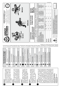
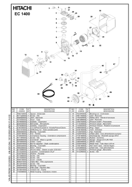
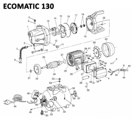
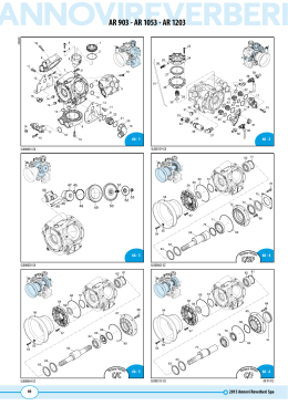
I
E
D
F
GARANZIA
I nostri prodotti sono garantiti per mesi
12 dalla consegna. La Ditta si assume la
responsabilità per tutti quei particolari
che presentassero difetti di materiale o di
lavorazione. Non è riconosciuta la garanzia
per cattiva manutenzione, anormale
impiego e per quelle parti non costruite
dalla Ditta. Le riparazioni dovranno essere
effettuate presso la fabbrica o da personale
autorizzato. Nello stesso istante in cui i
prodotti saranno manomessi da terzi, ogni
garanzia sarà ritenuta scaduta. Per ogni
verifica i prodotti dovranno essere inviati in
Porto Franco. Nel caso di effettiva necessità
di sostituzione di particolari sarà addebitato
il solo costo della mano d’opera. Per il vostro
fabbisogno di ricambi chiedete sempre
ricambi originali. In caso diverso non sarà
riconosciuta alcuna garanzia.
Numero per ordini telefonici:
(+39) 059.414.411
Numero per ordini con fax:
(+39) 059.253.505
GARANTÍA
Nuestros productos están garantizados
por 12 meses desde la fecha de la entrega.
Ninguna garantía será reconocida por malo
entretenimiento o por uso incorrecto de
los productos. Pidan siempre repuestos
originales. En caso contrario no se
reconocerá ninguna garantía.
GARANTIE
Die Firma gewährt eine Garantie von 12
Monaten, gerechnet vom Lieferdatum.
Zweck-fremder
Einsatz
und/oder
nachlässige Wartung schließen jede
Garantie aus. Im Bedarfsfall immer OriginalErsatzteile von der Firma anfordern.
Anderenfalls kann keine Garantie gewährt
werden.
GARANTIE
Nos produits sont garantis pour 12 mois
à partir de la date de livraison. Aucune
garantie ne sera reconnue, suite au
mauvais entretien ou emploi anormal des
produits. Pour tous vos besoins de pièces de
rechange, demandez toujours les rechanges
originaux. Au contraire, aucune garantie ne
sera reconnue.
Our products are guaranteed for a period
of 12 months after the date of delivery.
Warranty will not be acknowledged if the
products are not used according to the
manufacturer’s instruction or are badly
maintained. Always ask for original Spareparts, otherwise warranty will not be
acknowledged.
GB WARRANTY
Lubrificare con GRASSO Molykote G807
Lubricate with Molykote G807 GREASE
Avvitare con Loctite 5331 (Bianca)
Screw down with Loctite 5331 (White)
Lubrificare con GRASSO Molykote PG54
Lubricate with Molykote PG54 GREASE
Lubrificare con GRASSO Molykote 1000
Lubricate with Molykote 1000 GREASE
Lubrificare con GRASSO P40
Lubricate with P40 GREASE
Coppia serraggio Tolleranza +0/-10% Nm
Tightening torque tolerance +0/-10% Nm
Lubrificare con OLIO MOTORE
Lubricate with ENGINE OIL
Lubrificare con GRASSO MINERALE
Lubricate with MINERAL GREASE
Montare con PRESSA
Assemble with PRESS
Montare a caldo con RISCALDATORE
Assemble hot with HEATER
Avvitare con Loxeal 83-21 Frenafiletti FORTE (Verde)
Screw down with Loxeal 83-21 STRONG (Green)
thread sealer
Avvitare con Loxeal 55-14 Frenafiletti MEDIO (Rosso)
Screw down with Loxeal 55-14 MEDIUM (Red) thread
sealer
Avvitare con Loxeal 24-18 Frenafiletti DEBOLE (Porpora)
Screw down with Loxeal 24-18 WEAK
(Purple) thread sealer
Incollare con Loctite 454
Glue with Loctite 454
Spruzzare un velo di Molykote D-321R Spray
Spray on a light coat of Molykote D-321R
Sigillare con Loxeal 59-10
Seal with Loxeal 59-10
Sigillare con Arexons Mastice
Seal with Arexons Filler
Sigillare con Arexons MOTORSIL D
Seal with Arexons MOTORSIL D
Incollare con Biadesivo acrilico VHB-3M 4945
Glue with VHB-3M 4945 acrylic biadhesive
Avvitare con Loctite 2701 Frenafiletti FORTE (Verde)
Screw down with Loxeal 83-21 STRONG (Green)
thread sealer
Prescrizioni per Montaggio
Prescription for Assembly
Grupos de mando
Gruppi comando
GI 40
RM 40
Member of
GI 40
RM 40
AT E N Ç Ã O :
ATTENZIONE:
AT TENTION:
ACHTUNG:
AT E N C I Ó N :
AT TENTION:
80
80
l/min
21,1
21,1
gpm (US)
OUTPUT
DÉBIT
LEISTUNG
CAUDAL
PORTATA
40
40
bar
580
580
psi
PRESSURE
PRESSION
DRUCK
PRESIÓN
PRESSIONE
2 (+1)
2 (+1)
N. VALVES
N. ROBINETS
N. VENTILEN
N. ROBINETS
N. RUBINETTI
This manual must be read before beginning installation of the unit.
Ce livret doit être lu avant d’installer et d’employer le produit.
Das vorliegende Handbuch ist vor der Installation und dem Gebrauch des Produkts aufmerksam zu lesen.
Este manual debe ser leído antes de proceder a la instalación Y uso del producto.
Este manual deve ser lido antes de proceder à la instalação e ao uso do producto.
Il presente libretto va letto prima di procedere all’installazione ed uso del prodotto.
CONTROL UNITS
GROUPES DE COMMANDE
BEDIENUNGSARMATUREN
GRUPOS DE MANDO
GRUPPI COMANDO
1,6
1,6
kg
WEIGHT
POIDS
GEWICHT
PESO
PESO
TECHNICAL DATA / DONNÉES TECHNIQUES / TECHNISCHE ANGABEN
CARACTERÍSTICAS TÉCNICAS / CARACTERÍSTICAS TÉCNICAS / CARATTERISTICHE TECNICHE
Remote Control
Groupes de commande
Separate Bedienungsarmaturen
Via M.L.King,3 - 41122 Modena (Italy)
Tel. (+39) 059.414.411 - Telefax (+39) 059.253.505
E - Mail Italia: [email protected]
E - Mail export: [email protected]
ANNOVI REVERBERI S.p.A.
cod. 99371-HR
Characteristics and descriptions are not binding. -Données descriptions et illustrations n’ engagement pas le constructeur. - Angaben, Beschreibungen, und illustrationen sind nicht
verbindlich. - Noticias y ilustraciones no son empeñativas. - Os dados, descrições e ilustrações são fornecidos a título informativo e não comprometem o fabricante. - Dati, descrizioni ed
illustrazioni sono forniti a titolo indicativo e non impegativo.
Ver
sione-Version
22
18
23
32
21
17
24
37
Ver
sione-Version
19
18
8
20
38
25
33
30
6
16
14
36
28
13
12
15
31
11
10
7
AR 503 - AR 713 - AR 813
5
1
6
42
41
36
3
39
4
2
43
39
3
ione-Version
Vers
39
2-1
SL000113-GY
Pos
1
2
3
4
5
6
7
8
10
1
12
13
14
15
16
17
18
19
20
21
22
23
24
25
28
30
31
32
33
36
37
38
39
41
42
43
Cod.
620220
130171
130491
390270
450110
550350
550545
180370
320420
110121
110120
110122
320433
320511
390140
390141
550460
550440
320410
320480
320460
320470
320490
320450
320440
110190
230120
320406
450145
550450
110130
160660
880830
1923
180101
110131
1040790
1150580
130492
Descrizione
Description
Gruppo comando
Control unit
Tappo
3/8” G
Plug
3/8” G - 1/2” G M-M DX Cock
Rubinetto
Dado
M8
Nut
Sede
Seat
Guarnizione OR
Ø 23,81X2,62
O-ring
Manometro
Pressure gauge
Vite
TE M8x25
Screw
Molla
Spring
Pastiglia
Plug
Pastiglia
Plug
Pastiglia
Plug
Funghetto completo
Stem
Guarnizione OR
Ø 37,8x4
O-ring
Guarnizione
Gasket
Guarnizione
Gasket
Curva
Ø 18
Elbow
1/2” G - 3/4 G M-M Fitting
Raccordo
Castello valvola
Body valve
Perno
Hub pin
Forcella
Fork
Leva
Lever
Supporto
Support
Piattello
Wobble plate
Ghiera
Ring nut
Molla
Spring
Piattello
Wobble plate
Staffa
Bracket
Flangia
Flange
Girello
3/4” G
Ring nut
Girello
1/2”
Ring nut
Vite
TE M8x35
Screw
Guarnizione OR
Ø 15,54x2,62
O-ring
Kit valvola regolazione
Guarnizione OR
Girello
Girello
Portagomma
Rubinetto
Valve kit adjustment
Ø 17,5x2
1/2”
3/4”G
Ø 13
O-ring
Ring nut
Ring nut
Hose tail
3/8” G - 1/2” G M-M SX Cock
Non compreso nel GI 40 - No part of GI 40
Q.ty
1
1
2
2
1
2
1
2
1
1
1
1
1
1
1
1
1
1
1
2
1
1
1
1
1
1
1
1
1
1
1
2
2
1
1
3
1
1
1
Note
C20
sp_gi40.pdf
628650
GI 40
C20
0-80 bar
C20
Vulkolan
Gomma
Viton
Viton
KIT 1921
Pastiglie gomma
Buna valve seats
C10
KIT 1922
KIT 1925
Pastiglie Vulkolan
Vulkolan valve seats
Pronto intervento
Maintenance repair
Pos.
Q.ty
Pos.
Q.ty
Pos.
Q.ty
11
5
11
5
5
10
11
12
13
14
1
1
1
1
1
1
Pos.
Q.ty
1158600
RM 40
AR 503 - AR 713
AR 813
AR 30-50
AR 503 - AR 713
AR 813
30
31
6
13
35
50
51
1
2
3
13
47
34
35
34
35
13
34
48
34
49
49
13
34
36
48
4
47
42
32
29
36
5
4
28
39
44
43
4
10 11
41
12 13 14
18
15
45
16
46
9
AR 503 - AR 713
AR 813
26
39
16 17
39
26
20
22
21
40
27
23
24
3-1
38
37
Pos
1
2
3
4
5
6
9
10
11
12
13
14
15
16
17
18
20
21
22
23
24
26
27
28
29
30
31
32
34
35
36
37
38
39
40
41
42
43
Cod.
550460
800343
800342
550450
390180
550545
1151010
1040690
1150520
680560
1040640
1040630
1040631
880830
1040621
1150560
1150600
1150540
1150510
780330
1150530
394760
1150550
1150570
130491
130171
1150500
1150590
390311
180431
1040770
1040790
1150580
1040760
480550
1150650
110131
1150660
130492
1040950
550370
Descrizione
Description
Curva
Ø 18
Elbow
Portagomma
Ø 20
Hose tail
Portagomma
Ø 16
Hose tail
Girello
3/4” G
Ring nut
Guarnizione OR
Ø 18,72x2,62
O-ring
Manometro
Pressure gauge
Isometrico
Manometro
Pressure gauge
Forcella
Fork
Sede
Seat
Vite
TCEI M6x16
Screw
Valvola
Valve
Membrana
Diaphragm
Membrana
Diaphragm
Guarnizione OR
Ø 15,54x2,62
O-ring
Pistone
Piston
Distanziale
Spacer
Anello
Ring
Perno
Hub pin
Corpo
superiore
Body
Vite
TCEI M6x20
Screw
Ghiera
Ring nut
Molla
Spring
Manopola
Knob
Ghiera
Ring nut
3/8” G - 1/2” G M-M DX Cock
Rubinetto
Tappo
3/8” G
Plug
Corpo valvola
Valve body
Staffa
Bracket
Rondella
Washer
Vite
TE M8x16
Screw
Raccordo
Fitting
Girello
3/4”G
Ring nut
Portagomma
Ø 13
Hose tail
Raccordo
3/4” G M
Fitting
Anello
seeger Øe 12
Ring
Vite
TCTC M3x60
Screw
Girello
1/2”
Ring nut
Distanziale
Spacer
3/8” G - 1/2” G M-M SX Cock
Rubinetto
Copiglia
Split pin
Curva
Ø 25
Elbow
Q.ty
1
1
1
1
4
1
1
1
1
1
1
1
1
4
1
1
2
1
1
4
1
1
1
1
2
1
1
1
2
2
1
2
2
1
1
1
3
1
1
1
1
Note
Optional
Optional
0-80 bar
0-50-80bar
sp_rm40.pdf
UN000493-GF
Pos Cod.
Descrizione
44 550242 Girello
1” G
45 550350 Guarnizione OR
Ø 23,81X2,62
46 800720 Raccordo
3/4” G - 1” G F-M
47 960160 Guarnizione OR
Ø 17,86x2,62
48 1040810 Portagomma
49 1040800 Ghiera
50 110130 Girello
1/2”
51 450145 Flangia
Inox C10
Inox
Desmopan
NBR
Description
Ring nut
O-ring
Fitting
O-ring
Hose tail
Ring nut
Ring nut
Flange
Q.ty
Note
1
1
1
2
2
2
1
1
Non compreso nel RM 40 - No part of RM 40
Compreso nella pompa - Part of pump
C10
KIT 1988
KIT 1989
OR
O-Rings
C20
C5
Pos.
Q.ty
4
13
2
4
Pos.
Pronto intervento
Maintenance repair
Q.ty
Pos.
Q.ty
Pos.
Q.ty
4
6
9
11
12
13
15
17
21
22
2
1
1
1
1
4
1
1
1
1
23
24
37
38
40
42
1
1
1
1
1
1
F
DESCRIPTION ET MODE D’UTILISATION
L’unité de commande réglé la pression d’utilisation dans la distribution du liquide d’arrosage. Les chiffres rappelés dans le texte correspondent aux repères sur l’éclaté.
GB
DESCRIPTION AND USE
The control unit is designed for regulating working pressure in the
distribution of sprayed liquids. Numbers in the text refer to the
exploded view of the product.
MONTAGE SUR LA POMPE
1.Lubrifier et monter les joints toriques sur le corps de la pompe en
plaçant ce dernier dans le conduit de refoulement de la pompe.
2.Raccorder le retour directement à la citerne, sans étranglements.
3.Raccorder les tuyaux HP aux robinets en sortie.
INSTRUCTIONS DE SÉCURITÉ
Conserver ce manuel avec le plus grand soin. Lire et respecter les
instructions de sécurité ci-dessous:
• Ne pas utiliser le produit avec des fluides inflammables ou ayant
des caractéristiques incompatibles avec le fonctionnement correct du produit lui-même.
• L’installation du produit doit être effectuée par un personnel
qualifié.
MODE D’UTILISATION POUR GI 40
1.Suivre les instructions de fonctionnement de la pompe.
2.Contrôler les fuites éventuelles du circuit hydraulique à la hauteur
des jonctions et des raccords, en faisant circuler de l’eau.
3.Régler la pression par l’engagement du tirant (21) dans l’une des
quatre encoches jusqu’à trouver la bonne pression d’utilisation.
Pour modifier légèrement la pression, agir sur le plateau de réglage
(22).
4.Laver l’unité de commande entièrement à l’eau après le travail. Veiller à éliminer toute stagnation de produits agressifs.
MODE D’UTILISATION POUR RM 40
1.Suivre les instructions de fonctionnement de la pompe.
2.Contrôler les fuites éventuelles du circuit hydraulique à la hauteur
des jonctions et des raccords, en faisant circuler de l’eau.
3.La rotation à droite de l’accoupleur frontal (21) commande le retour
(ou décharge) rapide au réservoir. Vice versa, sa rotation à gauche
alimente les sorties vers les utilisations.
4.La poignée (23) règle la pression d’utilisation: une rotation dans le sens
des aiguilles d’une montre augmente la pression (+); une rotation
dans le sens contraire diminue la pression (-).
5.Laver l’unité de commande entièrement à l’eau après le travail. Veiller à éliminer toute stagnation de produits agressifs.
MONTAGE A DISTANCE
1.Monter solidement la bride.
2.Lubrifier et monter les joints toriques sur le corps de la pompe en
plaçant ce dernier dans la fixation.
3.Assembler les raccords rapides au tube HP de raccordement avec la
pompe, puis brancher au refoulement de la pompe.
4.Raccorder la décharge directement à la citerne, sans étranglements.
5.Raccorder les tuyaux HP aux robinets en sortie.
INSTALLATION ON PUMP
1.Lubricate and install the O-rings on the body and attach the
body to the pump outlet line.
2.Connect the drain port to the tank directly without intermediate flow restriction elements.
3.Connect the high pressure hoses to the outlet valves.
REMOTE INSTALLATION
1.Firmly secure the mounting bracket.
2.Lubricate and install the O-rings on the body and fit the latter to
the coupling.
3.Connect the quick couplings to the high pressure line from the
pump and then connect to the pump outlet.
4.Connect the drain to the tank directly, without flow restriction
elements.
5.Connect the high pressure hoses to the outlet valves.
USE FOR RM 40
1.Refer to the pump user handbook.
2.Check for possible leaks in the hydraulic circuit from connections and unions by circulating water through the system.
3.Rapid drain to tank is commanded by turning the front coupling
(21) to the right. Turn the coupling to the left to connect the
outlets port to the users.
4.Use knob (23) to regulate working pressure: turn clockwise to
increase pressure (+), counter clockwise to decrease (-).
5.When you finish work flush the control unit with water to remove any internal deposits of aggressive products.
USE FOR GI 40
1.Refer to the pump user handbook.
2.Check for possible leaks in the hydraulic circuit from connections and unions by circulating water through the system.
3.Fit the connecting rod (21) in each of the four notches until you
identify the one that gives the desired working pressure. If the
pressure must be altered only slightly, use the adjustment plate
(22).
4.When you finish work flush the control unit with water to remove any internal deposits of aggressive products.
SAFETY INSTRUCTIONS
This manual must be stored carefully. Read and follow the following safety instructions:
• Do not use the unit with flammable liquids, or liquids with
characteristics not compatible with the correct functioning of
the unit.
• The installation of the unit must be carried out by qualified staff.
D
BESCHREIBUNG UND GEBRAUCH
Das Steueraggregat dient zur Einstellung des Betriebsdruckes bei
der Verteilung des Sprühmediums. Die in Klammern angegebenen
Zahlen beziehen sich auf die Explosionszeichnung des Produkts.
PUMPENMONTAGE
1.Die O-Ringe schmieren und an den Körper anbringen, danach
den Körper druckseitig an die Pumpe anschließen.
2.Die Abflußleitung direkt, ohne Drosselstellen, an den Tank anschließen.
3.Die Hochdruckleitungen an die Auslaßventile anschließen.
FERNMONTAGE
1.Den Bügel fest anbringen.
2.Die O-Ringe schmieren und an den Körper anbringen, danach
den Körper in den Anschluß stecken.
3.Die Schnellanschlüsse an die Hochdruckleitung zum Pumpenanschluß anbringen, danach druckseitig an die Pumpe anschließen.
4.Die Abflußleitung direkt, ohne Drosselstellen, an den Tank anschließen.
5.Die Hochdruckleitungen an die Auslaßventile anschließen.
GEBRAUCH FÜR RM 40
1.Siehe Betriebsanleitung der Pumpe.
2.Durch Wasserzirkulation überprüfen, ob im Hydraulikkreis an
den Anschlüssen bzw. Verbindungen Leckstellen bemerkbar
sind.
3.Bei Rechtsdrehung des Frontelements (21) wird der Schnellablaß in den Tank freigegeben, bei Linksdrehung werden die
Verbraucher versorgt.
4.Durch den Handgriff (23) läßt sich der Betriebsdruck einstellen.
Beim Drehen im Uhrzeigersinn wird der Druck erhöht (+), beim
Drehen gegen den Uhrzeigersinn verringert (-).
5.Nach dem Betrieb ist das Steueraggregat mit Wasser auszuspülen, um Rückstände aggressiver Produkte zu entfernen.
GEBRAUCH FÜR GI 40
1.Siehe Betriebsanleitung der Pumpe.
2.Durch Wasserzirkulation überprüfen, ob im Hydraulikkreis an
den Anschlüssen bzw. Verbindungen Leckstellen bemerkbar
sind.
3.Zur Druckregelung den Zugbolzen (21) in eine der vier Kerben
bis zum Erreichen des vorschriftsmäßigen Betriebsdruckes
stecken. Für die Feineinstellung des Druckes ist die Regelplatte
(22).
4.Nach dem Betrieb ist das Steueraggregat mit Wasser auszuspülen, um Rückstände aggressiver Produkte zu entfernen.
SICHERHEITSANLEITUNGEN
Vorliegendes Handbuch sorgfältig aufbewahren und folgende
Sicherheitsanleitungen aufmerksam lesen und beachten:
• Produkt nicht mit entzündbaren oder sonstigen Flüssigkeiten
verwenden, deren Eigenschaften mit einem einwandfreien
Betrieb des Produkts nicht vereinbar sind.
• Die Produktinstallation ist von qualifiziertem Fachpersonal vorzunehmen.
DESCRIZIONE E MODO D’USO
Il gruppo comando serve per la regolazione della pressione di
lavoro nella distribuzione del liquido per irrorazione. I richiami
numerici fanno riferimento al disegno esploso del prodotto.
I
DESCRIPCIÓN Y MODO DE USO
El grupo de mando sirve para regular la presión de trabajo en
la distribución de líquido para pulverización. Las indicaciones
numéricas se refieren al gráfico de despiece del producto.
MODALITÀ D’USO PER GI 40
1.Fare riferimento alle istruzioni operative della pompa.
2.Controllare facendo circolare acqua, eventuali perdite del circuito idraulico nelle giunzioni e nei raccordi.
3.Regolare la pressione mediante inserimento del tirante (21) in
una delle quattro tacche, fino a trovare la giusta pressione di
lavoro. Occorrendo variarla di poco, agire sul piattello registro
(22).
4.Lavare il gruppo comando internamente con acqua dopo il
lavoro, togliendo eventuali ristagni di prodotti aggressivi.
E
MONTAJE SOBRE LA BOMBA
1.Lubricar y montar las juntas tóricas sobre el cuerpo, introduciendo este último en el conducto de impulsión de la bomba.
2.Conectar directamente la descarga a la cisterna, sin producir
obstrucciones.
3.Conectar los tubos de alta presión a los grifos en salida.
MONTAJE A DISTANCIA
1.Montar el soporte firmemente.
2.Lubricar y montar las juntas tóricas sobre el cuerpo, introduciendo este último en la conexión.
3.Ensamblar los rácores rápidos al tubo de alta presión de conexión con la bomba y, luego, conectar al conducto de impulsión
de la bomba.
4.Conectar directamente la descarga a la cisterna, sin producir
obstrucciones.
5.Conectar los tubos de alta presión a los grifos en salida.
MODO DE USO PARA RM 40
1.Remitirse a las instrucciones operativas de la bomba.
2.Controlar, haciendo circular el agua, que no haya pérdidas ni
en las juntas y ni en los rácores del circuito hidráulico.
3.Girando el frontal (21) hacia la derecha, se manda la descarga
rápida en el depósito. Viceversa, girándolo a la izquierda, se
alimentan las salidas.
4.Mediante la perilla (23) se regula la presión de trabajo: girándola en el sentido de las manecillas del reloj, aumenta la presión (+), y en sentido contrario al de las manecillas del reloj,
disminuye (-).
5.Después del trabajo, lavar internamente con agua el grupo de
mando y quitar eventuales restos de productos agresivos.
MODO DE USO PARA GI 40
1.Remitirse a las instrucciones operativas de la bomba.
2.Controlar, haciendo circular el agua, que no haya pérdidas ni
en las juntas y ni en los rácores del circuito hidráulico.
3.Regular la presión mediante la inserción del espárrago (21) en
una da las cuatro ranuras, hasta encontrar la presión de trabajo correcta. Si se quiere variar ligeramente, actuar sobre el
disco de registro (22).
4.Después del trabajo, lavar internamente con agua el grupo de
mando y quitar eventuales restos de productos agresivos.
ISTRUZIONI PER LA SICUREZZA
È necessario conservare con cura il presente manuale, leggere e
rispettare le seguenti istruzioni per la sicurezza:
• Non utilizzare il prodotto con fluidi infiammabili o aventi caratteristiche non compatibili con il corretto funzionamento del
prodotto stesso.
• L'installazione del prodotto deve essere effettuata da personale
qualificato.
MODALITÀ D’USO PER RM 40
1.Fare riferimento alle istruzioni operative della pompa.
2.Controllare facendo circolare acqua, eventuali perdite del circuito idraulico nelle giunzioni e nei raccordi.
3.Ruotando a destra il frontale (21) si comanda lo scarico rapido
in serbatoio. Viceversa ruotandolo a sinistra si alimentano le
uscite agli utilizzi.
4.Mediante la manopola (23) si regola la pressione di lavoro:
in senso orario aumenta la pressione (+), in senso antiorario
diminuisce (-).
5.Lavare il gruppo comando internamente con acqua dopo il
lavoro, togliendo eventuali ristagni di prodotti aggressivi.
MONTAGGIO SULLA POMPA
1.Lubrificate e montate gli OR sul corpo, inserendo quest’ultimo
nel condotto di mandata della pompa.
2.Collegare lo scarico alla cisterna, senza strozzature, direttamente.
3.Collegare i tubi alta pressione ai rubinetti in uscita.
MONTAGGIO A DISTANZA
1.Montare saldamente la staffa.
2.Lubrificate e montate gli OR sul corpo, inserendo quest’ultimo
nell’attacco.
3.Assemblare i raccordi al tubo alta pressione di collegamento
con la pompa, quindi collegare alla mandata della pompa.
4.Collegare lo scarico alla cisterna, senza strozzature, direttamente.
5.Collegare i tubi alta pressione ai rubinetti in uscita.
INSTRUCCIONES PARA LA SEGURIDAD
Es necesario conservar con cuidado el presente manual, leer y
respetar las siguientes instrucciones para la seguridad:
• No utilizar el producto con fluidos inflamables o que tengan
características no compatibles con el correcto funcionamiento
del producto.
• La instalación del producto debe ser efectuada por personal
especializado.
Scaricare