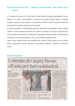
HIGHWAY
Brevettato - Patented
EP 2 642 028 A1
BARRIERA AUTOMATICA AD USO SUPER INTENSIVO PER PARCHEGGI E PASSAGGI AUTOSTRADALI
AUTOMATIC BARRIER FOR SUPER INTESIVE USE ON PARKINGS AND HIGHWAYS TOLL STATIONS
DESTRA
RIGHT
SINISTRA
LEFT
Operatore
Operator
Alimentazione
Power Supply
Lunghezza max asta
Max. boom lenght
Tempo di movimento
Operating time
min 1 s in apre
min 1,5 s in chiude
HIGHWAY DX
230V/50-60Hz
HIGHWAY SX
Servizio
Service
min 1 s in opening
min 1,5 s in closing
2÷3m
con rallentamenti attivati
with active slow speed in
approaching
ITALIANO pag. 04 / ENGLISH page 17
1
Codice
Code
AA50600
100%
AA50605
I
G
B
ISTRUZIONI DI SICUREZZA IMPORTANTI
PER L’INSTALLAZIONE
IMPORTANT SAFETY INSTRUCTIONS
FOR THE INSTALLATION
- ATTENZIONE PER LA SICUREZZA DELLE PERSONE É IMPORTANTE CHE VENGANO
SEGUITE TUTTE LE ISTRUZIONI
- ATTENTION FOR THE SAFETY OF THE PEOPLE IT IS IMPORTANT TO FOLLOW ALL THE
INSTRUCTIONS.
Barriera per gestione traffico veicolare non soggetta a EN12453
Barriera per gestione traffico veicolare non soggetta a EN12453
FOLLOW ALL INSTALLATION INSTRUCTIONS
SEGUIRE TUTTE LE ISTRUZIONI DI INSTALLAZIONE
1° - Questo libretto d’istruzioni è rivolto esclusivamente a del personale
specializzato che sia a conoscenza dei criteri costruttivi e dei dispositivi di
protezione contro gli infortuni per i cancelli, le porte e i portoni motorizzati
(attenersi alle norme e alle leggi vigenti).
2° - L’installatore dovrà rilasciare all’utente finale un libretto di istruzioni in accordo
alla EN 12635.
3° - Il cablaggio dei vari componenti elettrici esterni all’operatore (ad esempio
fotocellule, lampeggianti, ecc.) deve essere effettuato secondo la EN 60204-1.
4° - L’eventuale montaggio di una pulsantiera per il comando manuale del movimento
deve essere fatto posizionando la pulsantiera in modo che chi la aziona non si trovi
in posizione pericolosa; inoltre si dovrà fare in modo che sia ridotto il rischio di
azionamento accidentale dei pulsanti.
5° - Tenete i comandi dell’automatismo (pulsantiera, telecomando etc.) fuori dalla
portata dei bambini. I comandi devono essere posti ad un’altezza minima di 1,5 m
dal suolo e fuori dal raggio d’azione delle parti mobili.
6° - Prima di eseguire qualsiasi operazione di installazione, regolazione, manutenzione
dell’impianto, togliere la tensione agendo sull’apposito interruttore magnetotermico
collegato a monte dello stesso.
1° - This handbook is exclusively addressed to the specialized personnel who
knows the constructive criteria and the protection devices against the accidents
for motorized gates, doors and main doors (follow the standards and the laws in
force).
2° - The installer will have to issue to the final user a handbook in accordance with
the EN 12635.
3° - The wiring harness of the different electric components external to the operator
(for example photoelectric cells, flashlights etc.) must be carried out according to
the EN 60204-1.
4° - The possible assembly of a keyboard for the manual control of the movement must
be done by positioning the keyboard so that the person operating it does not find
himself in a dangerous position; moreover, the risk of accidental activation of the
buttons must be reduced.
5° - Keep the automatism controls (push-button panel, remote control etc.) out of the
children way. The controls must be placed at a minimum height of 1,5m from the
ground and outside the range of the mobile parts.
6° - Before carrying out any installation, regulation or maintenance operation of the
system, take off the voltage by operating on the special magnetothermic switch
connected upstream it.
LA DITTA RIB NON ACCETTA NESSUNA RESPONSABILITÀ per eventuali danni provocati
dalla mancata osservanza nell’installazione delle norme di sicurezza e delle leggi
attualmente in vigore.
THE RIB COMPANY DOES NOT ACCEPT ANY RESPONSIBILITY for possible damages
caused by the non observance during the installation of the safety standards and of the
laws in force at present.
CONSERVARE CON CURA QUESTE ISTRUZIONI
KEEP THESE INSTRUCTIONS WITH CARE
1° - Se non é previsto nella centralina elettrica, installare a monte della medesima
un’interruttore di tipo magnetotermico (onnipolare con apertura minima dei contatti
pari a 3 mm) che riporti un marchio di conformità alle normative internazionali.
Tale dispositivo deve essere protetto contro la richiusura accidentale (ad esempio
installandolo dentro quadro chiuso a chiave).
2° - Per la sezione ed il tipo dei cavi la RIB consiglia di utilizzare un cavo di tipo
H05RN-F con sezione minima di 1,5 mm2 e comunque di attenersi alla norma IEC
364 e alle norme di installazione vigenti nel proprio Paese.
1° - If it is not forecast in the electric gearcase, install a switch of magnetothermic type
upstream, (omni polar with minimum port of the contacts of 3 mm) with a check of
conformity to the international standards. Such devise must be protected against
the accidental lockup (for example by installing inside a locked board).
2° - For the section and the type of the cables, RIB advices to use a cable of the
H05RN-F type with minimum section of 1,5 sqmm and, in any case, to keep to
the IEC 364 standard and to the installation standards in force in your country.
N.B.: É obbligatoria la messa a terra dell’impianto
I dati descritti nel presente manuale sono puramente indicativi.
RIB si riserva di modificarli in qualsiasi momento.
Realizzare l’impianto in ottemperanza alle norme ed alle leggi vigenti.
N.B.: The system must be grounded
Data described by this manual are only Indicative and RIB reserves to modify them at
any time. Install the system complying with current standards and regulations.
2
I
G
B
1. Sistema motorizzato di riaggancio asta
2. Motoriduttore ventilato con servizio 100%
3. Molla bilanciamento asta
4. PLC
5. Inverter
6. Interruttore Generale
7. Sensori di prossimità
8. Fermi meccanici
3
1. Motorized system to re-engage the boom
2. Fan-cooled operator with service 100%
3. Boom balancing spring
4. PLC
5. Inverter
6. Main Power Switch
7. Proximity sensors
8. Mechanical stoppers
I
LAYOUT IMPIANTO
CARATTERISTICHE TECNICHE
con bande catarifrangenti.
- Freno elettronico in accostamento in apertura e chiusura.
- Dotata di centrale PLC ed Inverter per mantenimento della posizione di chiusura e gestione
del movimento dell’asta.
- Motoriduttore reversibile ad uso intensivo utilizzato per movimentare aste lunghe fino a 3 m.
- Il gruppo riduttore è lubrificato in bagno d’olio e non richiede manutenzione.
- La centrale PLC permette il collegamento di sensori magnetici, comandi separati apre/
chiude, fotocellule, chiusura automatica disattivabile da interruttore, ecc.
- La barriera è dotata di controllore logico, inverter, finecorsa elettrici di prossimità e finecorsa
meccanici.
- Sensori di prossimità per cambio velocità, finecorsa e rilevamento sgancio asta a seguito
di urto.
- HIGHWAY è la prima barriera al mondo dotata di asta con snodo motorizzato per il
riaggancio automatico dell’asta a seguito di urto violento (brevetto n° EP2642028).
- Sgancio dell’asta nel senso di marcia senza rimbalzo di ritorno e con asta in grado di
assorbire l’impatto (per asta in carbonio).
- Tempo di apertura/chiusura regolabile da 0,8 s a 6,3 s.
- È dotata di molla di bilanciamento testata per 5.000.000 di cicli.
- Grado di protezione IP54.
- HIGHWAY è trifase a 220V con servizio 100% per controllo traffico veicolare nei punti di
pedaggio autostradali e per i grandi parcheggi.
- Manutenzione eseguibile ogni 2.000.000 di cicli.
- Struttura in acciaio protetta con trattamento di cataforesi e verniciatura termoindurente
- In mancanza di corrente l’asta si solleva automaticamente senza intervento da parte del
personale.
N.B. È obbligatorio uniformare le caratteristiche dell’impianto alle norme e leggi vigenti.
- L’asta può essere in Carbonio con mousse per assorbimento urti e copertura protettiva Ø80
HIGHWAY
CARATTERISTICHE TECNICHE
Lunghezza max asta
DX Cod.AA50600
SX Cod.AA50605
2m
Carbonio
Cod. ACG8620
Gruppo molla
2,5 m
Carbonio
Cod. ACG8621
3m
Carbonio
Cod. ACG8622
ROSSA (CTC1392)
Tempo di apertura di default
GIALLA (CTC1399)
1,2 s apre / 1,7 s chiude *
Alimentazione e frequenza
230V 50-60 Hz
Potenza motore max
460 W
Assorbimento motore max
2A
Coppia max sull’albero porta asta
86 Nm
Cicli normativi
- 1s/1s
Servizio
100%
Peso max
kg 55 senza imballo, molla, mozzo e asta
Temperatura di lavoro
-10 + 55 °C
IP 54
Grado di protezione
** Gruppo riarmo automatico
SI
Mozzo per riarmo
NO
NO
ACG8627
Assorbimento in stand by 230V 50 Hz
0,35 A
0,6 A
1,2 A
Assorbimento in riarmo 230V 50/60 Hz
1,8 A
2,0 A
Assorbimento in stand by 230V 60 Hz
Assorbimento in lavoro 230V 60 Hz
NO
ACG4020DX - ACG4020SX
Mozzo per aste in Alluminio
Assorbimento in lavoro 230V 50 Hz
3 m Ø=80
Alluminio
Cod. ACG8501
1,8 A
-
0,5 A
0,8 A
1,4 A
2,0 A
2,0 A
* Questi sono i tempi rilevati con asta in carbonio da 2m, impostazione di fabbrica della frequenza dell’inverter e rallentamenti del movimento dell’asta in accostamento attivati.
** Il gruppo di riarmo automatico è applicabile solo a aste in Carbonio. È un dispositivo motorizzato (230Vac) controllato da un sensore che rileva lo sgancio dell’asta.
4
I
HIGHWAY con asta in carbonio
Misure in mm
HIGHWAY con asta in alluminio
Misure in mm
5
I
INSTALLAZIONE HIGHWAY
FISSAGGIO
- Cementare la piastra di fissaggio (cod. ACG8110) nella posizione ritenuta ideale.
- Aprire lo sportello utilizzando la chiave in dotazione (Fig. 1-2-3).
1
2
- Procedere al fissaggio della HIGHWAY utilizzando i dadi, le rondelle in dotazione e una
chiave esagonale n° 19.
3
TARATURA MOLLA ROSSA
Molla fornita e montata nella barriera regolata per asta in
carbonio 2 m (cod. ACG8620)
- Con lo sportello aperto svitare le 3 viti che fissano il quadro elettronico, quindi posizionatela
a lato come da figura 4.
4
5
6
7
8
9
- Togliere il coperchio svitando i due dadi a farfalla posizionati all’interno della colonna sotto
il supporto motore nel vano del quadro elettronico (Fig. 5-6).
- Svitare e togliere il controdado (Fig.7).
- Avvitare il dado con chiave a cricca da 22, come da TABELLA TARATURA MOLLE
sottostante in base all’asta utilizzata (Fig. 8-9-10-11-12).
ATTENZIONE: in caso di utilizzo di aste in alluminio sostituire la molla ROSSA con
la molla GIALLA.
- Rimontare il quadro elettronico (Fig. 13).
6
I
TABELLA TARATURA MOLLE
ASTA
TIPO DI MOLLA
2 m Carbonio Cod. ACG8620
2,5 m Carbonio Cod. ACG8621
323 mm
ROSSA
307 mm
GIALLA
307 mm
293 mm
M
3 m Carbonio Cod. ACG8622
3 m Alluminio Ø=80 Cod. ACG8501
MISURA M
(Fig. 14)
14
7
10
11
12
13
I
MONTAGGIO MOZZO E ASTA
MOZZO A SGANCIO CON RIARMO AUTOMATICO PER ASTE IN
CARBONIO (Fig. 15)
- Prendere la linguetta ad incastro 8x7x20 ed inseritela nella sede dell’albero porta mozzo
(Fig. 16-17).
- Montare il mozzo sull’albero in corrispondenza dello spacco con linguetta bloccandolo con
2 viti TCEI 10x70 inox, 4 rondella 10x20 inox e 2 dadi M10 autobloccanti (Fig.18-19-20).
ATTENZIONE: Il serraggio delle viti deve essere eseguito in modo alternato così
che il mozzo risulti parallelo rispetto all’albero porta mozzo.
15
16
17
18
22
- Togliere i tappi di protezione ai connettori posti sul fianco della colonna (Fig. 21-22).
- Collegare il connettore del sensore di sgancio asta (Fig. 23).
- Collegare il connettore del motore 2 di riarmo asta (Fig. 24-25).
19
20
21
23
24
25
MONTAGGIO ASTA IN CARBONIO
- Controllare che la superficie scoperta dell’asta sia ben pulita e
che all’estremità sia presente il sistema di tenuta (Fig. 26).
- Inserire la parte scoperta dell’asta nel mozzo porta asta (Fig.
27) prestando attenzione ad inserire il tappo posto
all’estremità dell’asta in carbonio orientato correttamente
rispetto alla bussola in nylon situata sul mozzo di
riaggancio (Fig. 28).
27
- Raggiunto il fondo ruotare l’asta in modo che il sistema di tenuta
posto all’estremità si innesti (Fig. 29).
ATTENZIONE: la cerniera della copertura d’asta deve
rimanere dalla parte del movimento dell’asta (Fig. 30).
26
29
28
8
30
I
- Portare manualmente l’asta in posizione orizzontale.
- Tirare con chiave a brugola n° 5 le 2 viti di tenuta asta (Fig. 31-32).
- Montare la protezione utilizzando le rondelle e viti in dotazione (Fig. 33-34-35-36-3738-39).
31
32
36
33
34
35
37
38
39
- Rilasciare l’asta verificando che si alzi fino al raggiungimento della completa apertura.
In caso l’asta non si alzi, verificare il corretto tiraggio della molla (Fig. 40-41) come
riportato nell’apposita TABELLA TARATURA MOLLE.
40
41
42
43
46
47
MONTAGGIO MOZZI PER ASTE IN ALLUMINIO
- Prendere la linguetta ad incastro 8x7x20 ed inserirla nella sede dell’albero porta mozzo
(Fig. 44-45).
- Montare il mozzo sull’albero in corrispondenza dello spacco con linguetta bloccandolo con
2 viti TCEI 10x70 inox, 4 rondelle 10x20 inox e 2 dadi M10 autobloccanti (Fig. 46-47).
ATTENZIONE: Non serrare a fondo solo una delle due viti.
Il serraggio delle viti deve essere eseguito in modo alternato così che il mozzo
risulti fissato parallelo rispetto all’albero porta mozzo.
44
45
9
I
MONTAGGIO ASTA Ø 80
- Dopo aver montato il mozzo, montare il cavallotto di tenuta asta Ø80 avvitando parzialmente
le viti composta da:
n° 4 viti TCEI 8 x 20 inox n° 4 rondelle piane 8 x 16 inox n° 4 rondelle grower da 8 mm
(Fig. 54).
- Inserire l’asta ø 80 nel cavallotto (Fig. 55) facendo rimanere la parte del profilo dove
vengono fissati gli accessori parallela e frontale al pavimento (Fig. 56).
54
55
56
57
58
59
- Serrare a fondo le viti (Fig. 57).
- Portare manualmente l’asta in posizione orizzontale.
- Rilasciare l’asta verificando che si alzi fino al raggiungimento della completa apertura.
In caso l’asta non si alzi, verificare il corretto tiraggio della molla (Fig. 58-59) come
riportato nell’apposita TABELLA TARATURA MOLLE.
10
I
REGOLAZIONE FINECORSA ELETTRICI
Posizionare i finecorsa elettrici rispettando le misure indicate in tabella facendo riferimento al disegno sottostante.
Dopo aver regolato e fissato i finecorsa 3 e 4, posizionare i finecorsa 1 e 2 a contatto con i rispettivi finecorsa 3 e 4.
MISURA A
finecorsa 3 di rallentamento in apertura
MISURA C
finecorsa 4 di rallentamento in chiusura
2 m Carbonio cod. ACG8620
32 mm
34 mm
2,5 m Carbonio cod. ACG8621
37 mm
35 mm
3 m Carbonio cod. ACG8622
42 mm
37 mm
3 m Alluminio Ø 80 cod. ACG8501
49 mm
40 mm
ASTA
11
I
COLLEGAMENTI ELETTRICI
CLB
R2
R1
IG
A1
PLC
INV
C1
CLA
IG
Interruttore generale 16 A
R1
Rele’ comando M2 - velocita’ lenta riaggancio asta
R2
Rele’ comando M2 di riaggancio asta
C1
Condensatore 4 µF per M2
A1
Alimentatore 24Vdc 2,5A
PLC
Controllore logico per gestione comandi e sicurezze
INV
Inverter pilotaggio M1
CLA
Morsettiera comandi e segnalazioni
CLB
Morsettiera finecorsa e sicurezze
12
I
MORSETTIERA COMANDI E SEGNALAZIONI - CLA
CLA
APRE CHIUDE ECATTCA ASTA ASTA
ALTA BASSA
CAT
230 Vac
ASTA
SGANCIATA
SEGNALAZIONI POSIZIONI ASTA
MORSETTO
DESCRIZIONE
NOTE AGGIUNTIVE
1
Comune comandi
2
Comando apre
3
Comune comandi
4
Comando chiude
5
Comune per ECAT e TCA
6
ECAT = contatto per l’esclusione della chiusura immediata dopo il transito tramite
Se il contatto è chiuso si esclude la chiusura immediata dopo il transito.
interruttore esterno.
7
TCA = contatto per abilitare il tempo di chiusura automatica tramite interruttore
Se il contatto è chiuso si abilita la chiusura dopo un tempo di 10 secondi
esterno.
8
9
10
11
12
13
Contatto normalmente aperto NO
Contatto normalmente aperto NO
Segnalazione stato barriera aperta
Contatto normalmente aperto che si chiude a barriera aperta
Segnalazione stato barriera chiusa
Contatto normalmente aperto che si chiude a barriera chiusa
Segnalazione stato asta sganciata
Contatto normalmente aperto che si chiude con asta sganciata
14
Comune opzione comandi
15
CAT = contatto per chiusura immediata dopo il transito
Contatto NC* che si apre al transito, per esempio tramite una fotocellula che rileva
il passaggio.
Collegamenti di terra
N-F
Alimentazione di rete 230Vac 50/60 hz
* È possibile richiedere il contatto NO.
13
I
MORSETTIERA FINECORSA E SICUREZZE - CLB
TX
RX
CONTATTO NC
FOTOCELLULE
INTERRUTTORE
SPORTELLO
BARRIERA
JUMP
ALIMENTAZIONE
24Vdc PER
FOTOCELLULE
MORSETTO
16
DESCRIZIONE
NOTE AGGIUNTIVE
+ 24V per alimentazione finecorsa di fine apertura e rallentamento in apertura
Filo marrone
17
- 24V per alimentazione finecorsa di fine apertura e rallentamento in apertura
Filo blu
18
Contatto finecorsa di rallentamento in apertura
Filo nero
19
Contatto finecorsa di fine apertura
Filo nero
20
+ 24V per alimentazione finecorsa di fine chiusura e rallentamento in chiusura
Filo marrone
21
- 24V per alimentazione finecorsa di fine chiusura e rallentamento in chiusura
Filo blu
22
Contatto finecorsa di rallentamento in chiusura
Filo nero
23
Contatto finecorsa di fine chiusura
Filo nero
24
+ 24V per alimentazione finecorsa asta sganciata o per alimentazione e contatto
comune di eventuale fotocellula esterna
Filo 2 - sensore asta sganciata
25
- 24V per alimentazione finecorsa asta sganciata o per eventuale alimentazione
Filo 3 - sensore asta sganciata
fotocellula esterna
26
Contatto asta sganciata
Filo 1 - sensore asta sganciata
27
Contatto nc fotocellula
Tramite fotocellula esterna opzionale
Contatto pulsante/interruttore di sicurezza sportello barriera
Contatto nc che si apre a sportello aperto. Il personale abilitato può attivare
manualmente l’interruttore tirando verso l’esterno il suo perno in plastica.
Previsione per esclusione comandi esterni (morsetti 1-2-3-4)
Tramite interruttore a chiave (opzionale)
28
29
30
31
32
A disposizione
33
A disposizione
Collegamento di terra M2
34
Collegamento riarmo attivo M2
Filo 1 M2 di riarmo asta
35
Collegamento comune M2
Filo 2 M2 di riarmo asta
36
Collegamento passivo M2
Filo 3 M2 di riarmo asta
14
I
ATTENZIONE: Se HIGHWAY non monta il mozzo con riarmo automatico togliere i relè 1 e 2.
Il finecorsa di sgancio asta non è presente quindi fate un ponte tra i morsetti
24 e 26.
PULSANTE DI APERTURA
Consente l’apertura a barriera chiusa.
Durante la chiusura, se premuto, inverte immediatamente il movimento in apertura.
Questo ingresso puo’ essere utilizzato anche per comandi di apertura tramite sensori a spira
magnetica.
PULSANTE DI CHIUSURA
Consente la chiusura a barriera aperta.
Durante l’apertura, se premuto, memorizza il comando dato e a fine apertura la barriera si
richiude immediatamente.
FUNZIONAMENTO FOTOCELLULE
Alimentazione 24Vdc ai morsetti 24 (+) e 25 (-).
Il contatto NC deve essere collegato ai morsetti 24 e 27.
Se impegnate a sbarra chiusa, l’apertura viene comunque consentita.
Se impegnate durante la chiusura fanno riaprire la barriera immediatamente.
Se impegnate a sbarra aperta, non consentono la chiusura.
A sbarra aperta e chiusura automatica attivata, se impegnate rinnovano il tempo di attesa della
chiusura automatica.
TEMPO DI ATTESA CHIUSURA AUTOMATICA (TCA)
Può essere attivato tramite interruttore esterno o ponticello a filo tra i morsetti 5 e 7.
Se sbarra aperta, il tempo si rinnova ogni qual volta si transiti davanti alle fotocellule.
Il tempo programmato di default è 10 s.
È possibile richiedere la procedura per regolare un tempo diverso (max 120 s) .
SGANCIO ASTA A BARRIERA CHIUSA
Questa l’operazione automatica di ripristino:
HIGHWAY apre a bassa velocità raggiungendo la totale apertura.
Dopo 1 secondo il motore M2 viene azionato per riagganciare l’asta.
2 Secondi dopo l’avvenuto riaggancio dell’asta, HIGHWAY chiude con velocità standard.
SGANCIO AD ASTA APERTA
Questa l’operazione automatica di ripristino: dopo 2 secondi con asta sganciata, viene
comandato il riaggancio.
L’asta poi rimane aperta.
TEMPO DI FUNZIONAMENTO MOTORE M2 PER RIAGGANCIO
Normalmente il tempo impiegato per riagganciare l’asta è di circa 3 s, tuttavia se esistono
impedimenti, il tempo si allunga automaticamente fino a massimo 10 s.
Se entro 10 s l’asta non ha raggiunto il finecorsa che segnala il riaggancio, il motore M2 si
ferma e il dispositivo di riaggancio rimane in attesa di un comando di apertura o chiusura per
ripetere l’operazione di riaggancio dell’asta.
La chiusura della barriera avviene solo se l’asta si trova in posizione verticale e correttamente
riagganciata (sensore di sgancio impegnato).
INTERRUTTORE DI SICUREZZA APERTURA SPORTELLO BARRIERA
L’apertura dello sportello attiva l’interruttore di sicurezza che toglie tensione al programmatore
logico, quindi tutte le funzioni sono bloccate.
Per eseguire verifiche funzionali e/o controlli da parte del personale autorizzato è necessario
attivare l’interruttore estraendo il perno plastico fino allo scatto.
Rimontando lo sportello, il perno dell’interruttore si riposizionerà riattivando la sicurezza.
CHIUSURA DA AVVENUTO TRANSITO (CAT)
Collegando il contatto NC di una fotocellula ai morsetti 14-15, a transito avvenuto viene
comandata l’immediata chiusura della barriera.
Durante la chiusura se si apre il contatto della fotocellula (per il passaggio di un nuovo veicolo)
si avrà una immediata inversione in apertura con successiva chiusura alla richiusura del
contatto (transito del veicolo completato).
È possibile escludere questa funzione aprendo il contatto dell’interruttore o togliendo il
ponticello a filo collegato ai morsetti 5-6 (ECAT).
15
16
INTERRUTTORE SPORTELLO
ALIMENTAZIONE
230 VAC
N F
I.G.
16 A
29
28
31
30
+
+
MAN/AUT
0
1
-
-
0
2
1
I1
17
2
APRE
24VDC
2,5 A
16
I2
LSSO
0
18
LSO
CHIUDE
I4
I5
LSSC
3
0
4
8
MILLENIUM 3 CD20
I3
4
3
9
I6
5
20
10
IB
21
14
IC
12
CHIUSA
6
15
11
0
LS SGANCIATA
6
ID
7
IE
7
5
TCA
0
SGANCIATA
13
0
22
IF
8
IG
23
FINECORSA
ASTA CHIUSA 2
SEGNALE COMUNE
SEGNALE APRE
SEGNALE CHIUDE
SEGNALE VELOCITA ALTA
SEGNALE MANTENIMENTO COPPIA
CONTROLLO POSIZIONE ASTA
APERTA
0
19
LSC
FINECORSA
RALLENTAMENTO
IN CHIUSURA 4
CAT
FINECORSA
ASTA APERTA 1
ECAT
FINECORSA
RALLENTAMENTO
IN APERTURA 3
PHOTO NC
33
32
24
R1
26
MAN/AUT NON
COLLEGATO
25
FINECORSA
ASTA SGANCIATA 5
27
PHOTO
RX
U
T1
T2
T3
T4
T5
T6
F
W
3 PHASE
M1
V
INVERTER
B1
B2
B3
B4
B5
B6
B7
PHOTO
TX
N
34
1 PHASE
M2
35
µF
36
R2
I
OPTIONAL
Per i collegamenti ed i dati tecnici degli accessori attenersi ai relativi libretti di istruzione.
MOZZO
per asta Ø 80 mm
cod. ACG8548G
PIASTRA DI FISSAGGIO
RADIO RICEVITORI AD AUTOAPPRENDIMENTO
Piastra di fissaggio da interrare
cod. ACG8110
RX433/A
RX433/A 2CH
TELECOMANDO SUN
SUN 2CH
SUN CLONE 2CH
cod. ACG6052
cod. ACG6056
supereterodina con morsettiera
supereterodina bicanale con morsettiera
cod. ACG5056
cod. ACG5052
SENSORE A SPIRA MAGNETICA
SUN 4CH
SUN CLONE 4CH
Per apertura con automezzi
monocanale - 230 Vac
monocanale - 12÷24 Vac/dc
bicanale - 12÷24 Vac/dc
cod. ACG6054
cod. ACG6058
NOVA - NOVA WIRELESS
FOTOCELLULE NOVA - portata 25 m
cod. ACG8046
FOTOCELLULE NOVA WIRELESS - portata 25 m - durata batterie 3 anni
cod. ACG8047
COPPIA DI COLONNINE per NOVA
cod. ACG8039
17
cod. ACG9060
cod. ACG9063
cod. ACG9064
G
B
SYSTEM LAYOUT
TECHNICAL CHARACTERISTICS
- Electronic brake in combination during opening and closing.
- Equipped with PLC control unit and inverter for maintaining the closed position and boom
movement management.
- Reversible gearmotor for intensive use used to move long booms up to 3 m.
- The maintenance unit is lubricated by oil bath and requires no maintenance.
- The barrier is equipped with a logic controller, inverter, electric proximity limit switches and
mechanical stops.
- HIGHWAY is the first barrier in the world equipped with a boom with a motorized joint for
automatic release of the boom following a violent impact (patent No. EP2642028).
- Opening/closing time can be adjusted from 0.8s to 6.3s.
- The PLC control unit allows you to connect magnetic sensors, open/close separate controls,
photocells, automatic closing that can be deactivated by switch, etc.
- Proximity sensor for transmission speed, limit switch and detection of boom uncoupling
following an impact.
- Boom uncoupling in the operating direction without return rebound and with a boom that
can absorb the impact (for carbon boom).
- IP54 degree of protection.
- It is equipped with a balancing spring, tested for 5,000,000 cycles.
- HIGHWAY is three-phase 220V with 100% service to control vehicular traffic at highway toll
stations and large parking lots.
- In the absence of current, the boom will lift automatically without any staff intervention.
- The boom can be made of Carbon with foam for shock absorption and a Ø80 protective
cover with reflective strips.
- Average time from use without maintenance 15,000 hours.
- Steel structure protected by cataphoresis treatment and thermoset coating
N.B. It is obligatory to standardize the characteristics of the system to the rules and laws
in force.
HIGHWAY
TECHNICAL CHARACTERISTICS
Lunghezza max asta
DX Cod.AA50600
SX Cod.AA50605
2m
Carbon
Code ACG8620
Max. boom length
2,5 m
Carbon
Code ACG8621
3m
Carbon
Code ACG8622
RED (CTC1392)
Spring unit
YELLOW (CTC1399)
1,2 s open / 1,7 s close *
Default opening time
230V 50-60 Hz
Power supply and frequency
460 W
Max. motor power
2A
Max. motor absorption
86 Nm
Max. torque on the boom holder shaft
- 1s/1s
Regulatory Cycles
100%
Service
kg 55 without box, spring, hub and boom
Max. Weight
-10 + 55 °C
IP 54
Work temperature
Protection rating
YES
** Automatic reset unit
NO
NO
ACG8627
Aluminium Hub for boom
0,35 A
0,6 A
1,2 A
Power consumption while working 230V 50 Hz
1,8 A
2,0 A
Power consumption in reset 230V 50/60 Hz
Power consumption in stand-by 230V 60 Hz
NO
ACG4020DX - ACG4020SX
Hub for reset
Power consumption in stand-by 230V 50 Hz
3 m Ø=80
Aluminum
Code ACG8501
1,8 A
-
0,5 A
0,8 A
1,4 A
2,0 A
Power consumption while working 230V 60 Hz
* These are the times detected with a 2m carbon boom, factory setting of inverter frequency and slow downs of the movement of the boom enabled in combination.
** The automatic reset unit is only applicable to carbon booms.
It is a motorized device (230Vac) controlled by a sensor that detects the release of the boom.
18
2,0 A
G
B
HIGHWAY with carbon boom
Measurements in mm
HIGHWAY with aluminium boom
Measurements in mm
19
G
B
HIGHWAY INSTALLATION
FASTENING
- Cement the fastening plate (code ACG8110) in the position deemed ideal.
- Open the door using the key supplied (Fig. 1-2-3).
1
2
- Proceed to fastening the HIGHWAY using nuts, washers and a hex wrench No. 19.
3
RED SPRING CALIBRATION
Spring supplied and assembled in the barrier adjusted for 2 m
carbon boom (code ACG8620)
- With the door open, unscrew the 3 screws that secure the electronic panel, then position
it at the side, as shown in figure 4.
4
5
6
7
8
9
- Remove the cover by loosening the two butterfly nuts positioned inside the column under
the motor support in the compartment of the electronic panel (Fig. 5-6).
- Unscrew and remove the lock nut (Fig. 7).
- Tighten the nut with a 22 ratchet wrench, as per the SPRING CALIBRATION TABLE below
according to the boom used (Fig. 8-9-10-11-12).
CAUTION: If using aluminium booms, replace the RED spring with the YELLOW spring.
- Reassemble the electronic panel (Fig. 13).
20
G
B
SPRING CALIBRATION TABLE
BOOM
SPRING TYPE
2 m Carbon Code ACG8620
2,5 m Carbon Code ACG8621
323 mm
RED
307 mm
3 m Carbon Code ACG8622
293 mm
YELLOW
307 mm
M
3 m Aluminum Ø=80 Code ACG8501
M
(Pict. 14)
14
21
10
11
12
13
G
B
HUB AND BOOM ASSEMBLY
UNCOUPLING HUB WITH AUTOMATIC RESET FOR CARBON BOOMS
(Fig. 15)
- Take the 8x7x20 latch and insert it into the seat of the hub holder shaft (Fig. 16-17).
- Assemble the hub on the shaft in the correspondence with the latch, locking it with 2
stainless steel 10x70 TCEI screws, 4 stainless steel 10x20 washers and 2 M10 selflocking nuts (Fig.18-19-20).
15
16
17
18
22
CAUTION: The screws must be tightened alternately so that the hub is parallel with
respect to the hub holder shaft.
- Remove the protective plugs to the connectors located on the side of the column (Fig.
21-22).
- Connect the boom uncoupling sensor connector (Fig. 23).
- Connect the connector of motor 2 of the boom reset (Fig. 24-25).
19
20
21
23
24
25
CARBON ROD ASSEMBLY
- Check that the exposed surface of the boom auction is thoroughly
cleaned and that the sealing system is present at the end (Fig. 26).
system located at the end locks in (Fig. 29).
CAUTION: The hinge of the boom cover must remain on the
side of the movement of the boom (Fig. 30).
- Insert the exposed part of the boom into the boom holder hub
(Fig. 27) being careful to insert the plug at the end of the
boom, properly oriented in relation to the nylon bushing
located on the release hub (Fig. 28).
26
- Once the bottom is reached, rotate the boom so that the sealing
27
29
28
22
30
G
B
- Manually bring the boom to a horizontal position.
- Pull the 2 holding screws of the boom with Allen key No. 5 (Fig. 31-32).
- Assemble the protection using the washers and screws provided (Fig. 33-34-35-36-3738-39).
31
32
36
33
34
35
37
38
39
- Release the boom, checking that it rises until it reaches complete opening. If the boom does
not rise, check the correct pulling in the spring (Fig. 40-41) as shown in the appropriate
SPRING CALIBRATION TABLE.
40
41
42
43
46
47
ASSEMBLY OF ALUMINIUM HUB FOR BOOM
- Take the 8x7x20 latch and insert it into the seat of the hub holder shaft (Fig. 44-45).
- Assemble the hub on the shaft in the correspondence with the latch, locking it with 2
stainless steel 10x70 TCEI screws, 4 stainless steel 10x20 washers and 2 M10 selflocking nuts (Fig. 46-47).
CAUTION: Do not tighten to the bottom only one of the two screws.
The screws must be tightened alternately so that the hub is parallel with respect to
the hub holder shaft.
44
45
23
G
B
BOOM ASSEMBLY Ø 80
- After assembling the hub, assemble the boom seal jumper 80, by partially screwing the
screws composed of:
No.4 stainless steel 8 x 20 TCEI screws, No.4 stainless steel 8 x 16 flat washers No. 4
grower washers 8 mm (Fig. 54).
- Insert the boom Ø80 into the jumper (Fig. 55) making the part of the profile remain
where the accessories are fixed parallel and to front of the floor (Fig. 56).
54
55
56
57
58
59
- Tighten the screws to the floor (Fig. 57).
- Manually bring the boom to a horizontal position.
- Release the boom, checking that it rises until it reaches complete opening.
If the boom does not rise, check the correct pulling in the spring (Fig. 58-59) as shown in the
appropriate SPRING CALIBRATION TABLE.
24
G
B
ELECTRICAL LIMIT SWITCH ADJUSTMENT
Position the electrical limit switch, respecting the measurements shown in the table, making reference to the drawing below.
After adjusting and fastening limit switches 3 and 4, position limit switches 1 and 2 in contact with the respective limit switches 3 and 4.
MEASUREMENT A
limit switch 3 to slow down during opening
MEASUREMENT C
limit switch 4 to slow down during closing
2 m Carbon code ACG8620
32 mm
34 mm
2.5 m Carbon code ACG8621
37 mm
35 mm
3 m Carbon code ACG8622
42 mm
37 mm
3 m Aluminium Ø80 code ACG8501
49 mm
40 mm
BOOM
25
G
B
ELECTRICAL CONNECTIONS
CLB
R2
R1
IG
A1
PLC
INV
C1
CLA
IG
Mains power switch 16 A
R1
M2 command relay - speed slow release
R1
M2 command relay for boom release
C1
Capacitor 4 µF for M2
A1
24Vdc Power Supply 2.5A
PLC
Logic controller for management and safety commands
INV
M1 Inverter drive
CLA
Controls and signals terminal board
CLB
Safety limit and safety terminal block
26
G
B
CONTROLS AND SIGNALS TERMINAL BOARD - CLA
CLA
OPENCLOSE ECATTCA BOOM BOOM
UP DOWN
CAT
230 Vac
BOOM
DISENGAGED
BOOM POSITIONS SIGNALISATIONS
TERMINAL
DESCRIPTION
ADDITIONAL NOTES
1
Common commands
2
Command opens
3
Common commands
4
Command closes
5
Common to ECAT and TCA
6
ECAT = Contact for exclusion of the immediate closing after transit through the
external switch.
If the contact is closed, it exclude the immediate closure after transit.
7
TCA = contact to enable the automatic closing time via an external switch.
If the contact is closed, it enables the lock after a time of 10 seconds
Report of open barrier state
Contact normally open that closes with the barrier open
Report of closed barrier state
Contact normally open that closes with the barrier closed
Report of release boom state
Contact normally open that closes with the barrier closed
8
9
10
11
12
13
14
Common commands option
15
CAT = contact for immediate closure after transit
Normally open contact NO
Normally open contact NO
NC* contact that opens upon transit, for example by means of a photocell that detects
the passage.
Ground connections
N-F
Power supply 230Vac 50/60 Hz
It is possible to request the contact NO.
27
G
B
SAFETY LIMIT AND SAFETY TERMINAL BLOCK - CLB
TX
RX
PHOTOBEAMS
NC CONTACT
BARRIER COVER
SAFE SERVICE
INTERRUPTOR
JUMP
24Vdc
POWER SUPPLY
FOR PHOTOBEAMS
MORSETTO
16
DESCRIZIONE
NOTE AGGIUNTIVE
+ 24V for limit switch power supply at the end of opening and slow down in opening
Brown wire
17
- 24V for limit switch power supply at the end of opening and slow down in opening
Blue wire
18
Slowdown limit switch Contact in opening
Black wire
19
Slowdown limit switch Contact in opening
Black wire
20
+ 24V for limit switch power supply at the end of closing and slow down in closing
Brown wire
21
- 24V for limit switch power supply at the end of closing and slow down in closing
Blue wire
22
Slowdown limit switch Contact in closing
Black wire
23
Slowdown limit switch Contact in closing
Black wire
24
+ 24V for released boom limit switch power supply or for power supply and common
Wire 2 - Released boom sensor
contact of any external photocell
25
- 24V for released boom limit switch power supply or for any external photocell power
supply
Wire 3 - Released boom sensor
26
Released boom sensor
Wire 1 - Released boomsensor
27
Photocell NC contact
By means of optional external photocell
Barrier door button contact/safety switch
NC contact that opens with the door is open. The qualified personnel can manually
activate the switch by pulling its plastic pin outwards.
Forecast for excluding external commands (terminals 1-2-3-4)
by means of a key switch (optional)
28
29
30
31
32
Available
33
Available
M2 Ground connection
34
M2 active reset connection
Wire 1 M2 of boom reset
35
M2 common connection
Wire 2 M2 of boom reset
36
M2 passive connection
Wire 3 M2 of boom reset
28
G
B
CAUTION : If HIGHWAY does not assemble the hub with automatic reset, remove relay 1 and
2. The boom uncoupling limit switch is therefore not present, make a link between
terminals 24 and 26.
OPENING BUTTON
Allows opening with the barrier is closed.
During the closing, when pressed, it immediately reverses the opening movement.
This entry can also be used for opening commands via a magnetic loop sensors.
CLOSING BUTTON
Allows closing with the barrier open.
During opening, when pressed, it stores the command given and at the end of opening, the
barrier closes immediately.
PHOTOCELLS OPERATION
24Vdc power supply to terminals 24 (+) and 25 (-).
The NC contact must be connected to terminals 24 and 27.
If engaged with the bar closed, the opening is still allowed.
If engaged during closing, they make reopen the barrier immediately.
If engaged with the bar open, they do not allow closing.
With the bar open and closing automatically activated, if engaged they renew the automatic
closing waiting time.
AUTOMATIC CLOSING WAITING TIME (TCA)
It can be activated via external switch or wire jumper between terminals 5 and 7.
If the bar is open, the time is renewed whenever it crosses in front of the photocells.
The default programmed time is 10 s.
It is possible to perform the procedure to set a different time (Max 120 s).
BOOM UNCOUPLING WITH THE BARRIER CLOSED
This is the automatic reset operation:
HIGHWAY opens at low speeds, reaching full opening.
After 1 second motor M2 is driven to hang the boom.
2 Seconds after happened hook of the boom, HIGHWAY closes with speed standard.
UNCOUPLING WITH THE BOOM OPEN
This is the automatic reset operation: after 2 seconds with the boom uncoupled, the release
is commanded.
The boom then remains open.
M2 MOTOR OPERATING TIME FOR RECOUPLING
Normally, the time taken to recouple the boom is about 3 s, however, if there are impediments,
the time is automatically extended up to a maximum time of 10 s.
If within 10 s the boom has not reached the limit switch that signals the release, the M2 motor
stops and the uncoupling device waits for an open or close command to repeat the release
operation of the boom auction.
The closing of the barrier takes place only if the boom is found in the vertical position and
correctly released (uncoupling sensor engaged).
BARRIER DOOR OPEN SAFETY SWITCH
The opening of the door activates the safety switch that cuts the power to the logic controller,
then all functions are blocked.
To perform functional tests and/or inspections by authorized staff, it is necessary to activate
the switch by pulling out the plastic pin until it clicks.
When reassembling the door, the pin of the switch will reposition itself, reactivating the safety.
CLOSING FROM A TRANSIT (CAT)
By connecting the NC contact of a photocell to terminals 14-15, the transit commands the
immediate closure of the barrier.
During closing, if the photocell contact opens (for the passage of a new vehicle) there will be an
immediate reversal in opening with subsequent closing at the re-closing of the contact (transit
of the completed vehicle).
It is possible to exclude this function by opening the contact of the switch or removing the wire
jumper connected to terminals 5-6 (ECAT).
29
30
ALIMENTATION
230 VAC
N F
I.G.
16 A
29
28
31
30
+
+
MAN/AUT
0
1
-
-
0
2
1
I1
17
OPEN
2
I2
LSSO
0
18
LSO
CLOSE
I4
I5
LSSC
3
0
4
8
MILLENIUM 3 CD20
I3
4
3
9
I6
5
OPEN
0
19
LSC
SWITCH DOOR
24VDC
2,5 A
16
20
11
0
IC
6
15
14
21
12
6
ID
13
0
22
7
IE
7
5
TCA
0
IF
8
IG
23
LIMIT SWITCH
CLOSE 2
COMMON SIGNAL
OPEN SIGNAL
CLOSE SIGNAL
FAST SPEED SIGNAL
MAINTAINING TORQUE SIGNAL
CLOSE
DISLOCATED
REPORT BOOM
10
IB
LS DISLOCATED
LIMIT SWITCH
SLOW CLOSE 4
CAT
LIMIT SWITCH
OPEN 1
ECAT
LIMIT SWITCH
SLOW OPEN 3
PHOTO NC
33
32
24
R1
26
MAN/AUT NOT
CONNECTED
25
LIMIT SWITCH
DISLOCATED 5
27
PHOTO
RX
U
T1
T2
T3
T4
T5
T6
F
W
3 PHASE
M1
V
INVERTER
B1
B2
B3
B4
B5
B6
B7
PHOTO
TX
N
34
1 PHASE
M2
35
µF
36
R2
G
B
ACCESSORIES
For the connections and the technical data of the optional equipments follow the relevant handbooks.
FIXING HUB
for Ø 80 mm boom arm
code ACG8548G
BASE PLATE
CODE LEARNIG SYSTEM RADIORECEIVERS
Base plate.
code ACG8110
RX433/A
super eterodyne with terminal block
RX433/A 2CH super eterodyne, 2 channel and terminal block
RADIO TRANSMITTER SUN
SUN 2CH
SUN CLONE 2CH
cod. ACG6052
cod. ACG6056
code ACG5056
code ACG5052
METALLIC MASS DETECTOR
SUN 4CH
SUN CLONE 4CH
to open with vehicles
1 channel - 230 Vac
1 channel - 12÷24 Vac/dc
2 channels - 12÷24 Vac/dc
cod. ACG6054
cod. ACG6058
NOVA - NOVA WIRELESS
PHOTOCELLS NOVA - range 25 m
code ACG8046
PHOTOCELLS NOVA WIRELESS - range 25 m - 3 years batteries life code ACG8047
PAIR OF COLUMNS for NOVA
code ACG8039
31
code ACG9060
code ACG9063
code ACG9064
REGISTRO DI MANUTENZIONE
MAINTENANCE LOG
Il presente registro di manutenzione contiene i riferimenti tecnici e le registrazioni delle attività di installazione, manutenzione, riparazione e modifica svolte, e dovrà essere reso disponibile per eventuali ispezioni da parte di organismi autorizzati.
This maintenance log contains the technical references and records of installation works, maintenance, repairs and modifications, and must be made available for inspection purposes to authorised bodies.
ASSISTENZA TECNICA
TECHNICAL ASSISTANCE
CLIENTE
CUSTOMER
NOME, INDIRIZZO, TELEFONO - NAME, ADDRESS, TELEPHONE NUMBER
NOME, INDIRIZZO, TELEFONO - NAME, ADDRESS, TELEPHONE NUMBER
MATERIALE INSTALLATO
INSTALLED MATERIAL
Data
Date
Descrizione dell’intervento (installazione, avviamento, verifica delle sicurezze, riparazioni, modifiche)
Description of the operation (installation, start-up, adjustement, safety device check, repair, modifications)
32
Firma del tecnico
Technician’s signature
Firma del cliente
Customer’s signature
®
automatismi per cancelli
automatic entry systems
R.I.B. S.r.l.
25014 Castenedolo - Brescia - Italy
Via Matteotti, 162
Tel. ++39.030.2135811
Fax ++39.030.21358279 - 21358278
www.ribind.it - [email protected]
DICHIARAZIONE DI CONFORMITÁ
DECLARATION OF COMPLIANCE
Dichiariamo sotto la nostra responsabilità che l’operatore HIGHWAY è conforme alle seguenti norme e Direttive:
We declare under our responsibility that HIGHWAY operator is conform to the following standards:
EN 55014-1
EN 55014-2
EN 60335-1
EN 60335-2-103
2012
2009
2013
2010
EN 61000-3-2
EN 61000-3-3
EN 61000-6-1
EN 61000-6-2
2011
2009
2007
2006
EN 61000-6-3
EN 61000-6-4
2012
2012
Inoltre permette un’installazione a Norme
You can also install according to the following rules :
EN 13241-1 2004
Come richiesto dalle seguenti Direttive
As is provided by the following Directives
2006/95/CE
2004/108/CE
Il presente prodotto non può funzionare in modo indipendente ed è destinato ad essere incorporato in un impianto costituito da ulteriori elementi. Rientra
perciò nell’Art. 6 paragrafo 2 della Direttiva 2006/42/CE (Macchine) e successive modifiche, per cui segnaliamo il divieto di messa in servizio prima
che l’impianto sia stato dichiarato conforme alle disposizioni della Direttiva.
This product can not work alone and was designed to be fitted into a system made up of various other elements. Hence, it falls within Article 6, Paragraph
2 of the EC-Directive 2006/42 (Machines) and following modifications, to which respect we point out the ban on its putting into service before being
found compliant with what is provided by the Directive.
Legal Representative
(Rasconi Antonio)
33
ACG4020DX MOZZO RIAG.RAPIDO DX HIGHWAY
Codice
Denominazione Particolare
CME8219
SEMIGUSCIO INF. HIGHWAY
DRL66X18I
BA04021
GR.MOTORE RIARMO HIGHWAY
CME8220
CONTROFLANGIA HIGHWAY
DRL8X17I
ROND. PIANA 8.4X17X1.6 INOX
BA04024
GR.SGANCIO FINECORSA HIGHWAY
CME8222
BUSSOLA FISS.ASTA CARBON HGWY
DTB10X70I
VITE TCEI 10X70 INOX UNI 5931
BA04025
GRUPPO ALBERO RIARMO HIGHWAY
CME8223
BLOCCHETTO AGGANCIO ASTA HGWY
DTB6X16I
VITE TCEI 6X16 INOX
BA04030
CONFEZIONE VITERIA RIAG.RAPIDO
CME8224
TASSELLO ELASTICO FERMO ASTA H
DTB6X25I
VITE TCEI 6X25 INOX
CCA1681
SUPPORTO SNODO HIGHWAY
CME8230
BUSSOLA ANT.SNODO HIGHWAY
DTB6X30I
VITE TCEI 6X30 INOX UNI 5931
CCA1682
PIASTRINA MICRO SOND. HIGHWAY
CSU211
SUPPORTO LAM.STAMP.KLM PFL+205
DTB6X60I
VITE TCEI 6X60 INOX UNI 5931
CCA1683
CARTER SNODO HGWY
CTC1012
CHIAVETTA 20 7 8
DTB6X90I
VITE TCEI M6X90 UNI 5931 INOX
CCA1684
CARTER X PG BARRIERA HIGHWAY
CTC1214I
SPINA CIL.8X32 INOX
DTB8X45I
VITE TCEI 8X45 INOX 5931
CCM6205
CUSC. MOT. 6205ZZ 15 52 25
CTC1396
MOLLA AMMORTIZZATORE HIGHWAY
DTC4X20I
VITE TC.CR. 4X20 INOX
CEL1109
PRESS.+GHI.PG9 LCP09G+LCL09G
CVA1711
SACCHETTO CM 15X40 25MY
DTC6X10I
VITE TC.CR. 6X10 INOX 7687
CEL1731
SENSORE SGANCIO HIGHWAY
CVA2285
MOLLA GAS RAYFLEX 8X20X600-80N
DTE6X12I
VITE TE 6X12 INOX UNI 5739
CEL1736
GUAINA SPIRAL.PLIOSPIRE PA6 BK
DDD10MA
DADO AUTOB. 10MA ALTO
DTE8X25I
VITE TE 8X25 INOX
CEL1739
CONNETT.3POLI MASCHIO 8/7 PHOE
DDD8MAI
DADO AUTOB. 8MA INOX-DIN 982
DTR8X20I
VITE TTQST 8X20 INOX UNI 5732
CEL1740
CONNETTORE 4POLI MASCHIO 8/7 P
DDDB8MAI
DADO AUTOB. 8MA BASSO INOX 985
CME8218
SEMIGUSCIO SUP. HIGHWAY
DRL10X20I
ROND. PIANA 10X20 INOX
34
ROND. PIANA 6,6X18X2 INOX
DST10X70I
DTR8X20I
CCA1676
CCA1672
CSU211
CCA1686
CME8229
CME8214
GRB1001
CME8212
CVA2286
DRL8X17I
DDDB8MAI
CCA1670
CTC1015
CTC1012
CME8211
CCA1671
DRL6X24Z
CVA1406
DDFM6
CTC1398
CME8210
BA04027
DDD10MAI
DRL10X20I
CME8216
CVA2287
CEL1642
CEL1738
CTC1399
CTC1392
CME8217
DDD5MA
CCA1675
CEL1716
CEL1377
CEL1633
CEL1634
CME8234
DTC4X8Z
DRL4X16Z
DRL15X28Z CEL1723
DDMM14
CEL1722
CEL1635
CEL1643
CEL1636
CEL1741
CEL1737
CCA1687
CME8213
CEL1494
CCA1685
CEL1733
DRL5X10Z
DTC5X15Z
CVA1141
CVA1025
CCA1677
CCA1674
CCA1678
CEL1716
Codice
Denominazione Particolare
CEL1717
R* CAP.G.LO CMGF-M6 POI CEL142
CTC1399
MOLLA BIL. GIALLA ASTA ALLUMINIO
BA04027
TAMPONE FERMO MECCANICO
CEL1721
ZOCCOLO VITE - FD9472SMA
CVA1025
CILIND.SELETT.16 2251NK1RI4RLI
CCA1670
SUPPORTO RIDUT. RAL9005
CEL1722
C40A 1P+N C 16A 4,5KA - SNA9N1
CVA1141
TAPPO SERR.CARTER SUPER ART951
CCA1671
PIATTINO X FINECORSA
CEL1723
RELE’INNESTO2SC 24VCC 10A - FD
CVA1406
GHIERA KM 5 ECO S/R50 ZIN/NIC
CCA1672
SUPPORTO LATO ASTA RAL905
CEL1733
MICRO 3 POSIZ.OMRON D2D2100-
CVA2286
CATENA 2/1’X16/5’ ISO NR08B1-
CCA1674
PROTEZ.INTERNA PANNELLO
CEL1737
CONNETT.3POLI FEM 8/7 PHOENIX
CVA2287
MAGLIA GIUNZ.CATENA 2/1’X16/5’
CCA1675
COLONNA BARRIERA
CEL1738
CONNETT.4POLI FEM 8/7 PHOENIX
DDD10MAI
DADO AUTOB. 10MA INOX ALTO
CCA1676
COPERCHIO BARRIERA
CEL1741
TAPPO PHX 8-7 NERO PA1410604-6
DDDB8MAI
DADO AUTOB. 8MA BASSO INOX 985
CCA1677
PANNELLO BARRIERA
CME8210
ALBERO TRAINO SALDATO
DDFM6
DADO FARFALLA M6X25X14DFA 0600
CCA1678
SUPPORTO COMANDI
CME8211
DISTANZIALE LATO FINECORSA
DDMM14
DADO 14MA MEDIO UNI 5588
CCA1685
LEVETTA SERRATURA
CME8212
CAMMA X MOLLA Z25
DRL10X20I
ROND. PIANA 10X20 INOX
CCA1686
SUPPORTO FERMO MECCANICO
CME8213
TIRANTE MOLLA BILANCIAMENTO
DRL15X28Z
RONDELLA PIANA 15X28X6592 2,5
CEL1377
COND.4MF 450V CON CAVETTO
CME8214
DISTANZIALE FERMO MECCANICO
DRL4X16Z
ROND. PIANA 4.3X16X1.5
CEL1494
PRESSACAVO LCM20G M20x1,5
CME8216
PIATTELLO SUPERIORE MOLLA BIL.
DRL5X10Z
ROND. PIANA 5X10 ZINCATE
CEL1633
PLC CROUZET KILLENIUM 3SMARTCD
CME8217
PIATTELLO INFERIORE MOLLA BIL.
DRL6X24Z
ROND. PIANA 6X24 zincata
CEL1634
SENS.IND.IFM M12X1 PNPNOIF6001
CME8229
DISTANZIALE X ALBERO SALDATO
DRL8X17I
ROND. PIANA 8.4X17X1.6 INOX
CEL1635
ALIMENTATORE GAV SPD 24601B 60
CSU211
SUPPORTO LAM.STAMP.KLM PFL+205
DST10X70I
GRANO M10X70 INOX UNI 5923
CEL1636
INVERT.LEROY SOMER SKA12000025
CTC1012
CHIAVETTA 20 7 8
DTC4X8Z
VITE TC.CR. 4X8 UNI 7687
CEL1642
GUIDA CAVI ADES.310915 ELEKTRO
CTC1015
CHIAVETTA 35 7 8
DTC5X15Z
VITE TC.CR. 5X15 UNI 7687
CEL1643
GUARNIZIONE COPR.SPIG.DX2C 140
CTC1392
MOLLA BIL. ROSSA ASTA CARBONIO
DTR8X20I
VITE TTQST 8X20 INOX UNI 5732
CEL1716
GUIDA SUPP.TS35X1/7,5F OMEGA-W
CTC1398
ROSETTA DI SICUREZZA MB5
GRB1001
GR.RID.BON.A2 10 UH3-51 25 S05
35
HIGHWAY
COMPONENTI DA SOSTITUIRE OGNI 2.000.000 DI CICLI
COMPONENTS TO CHANGE EVERY 2.000.000 CYCLES
GRUPPO RICAMBIO HGW-2ML DX
GRUPPO RICAMBIO HGW-2ML SX
Questo prodotto è stato completamente progettato e costruito in Italia · Ce produit a été complètement développé et fabriqué en Italie · This product has been
completely developed and built in Italy · Dieses Produkt wurde komplett in Italien entwickelt und hergestellt · Artìculo totalmente proyectado y producido en Italia
®
automatismi per cancelli
automatic entry systems
25014 CASTENEDOLO (BS) - ITALY
Via Matteotti, 162
Tel. +39.030.2135811
Fax +39.030.21358279
www.ribind.it - [email protected]
Cod. CVA2258 - 01042014 - Rev. 01
BA03240DX
BA03240SX
Scarica