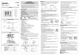
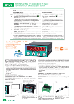
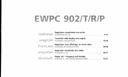
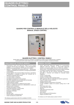
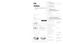
V3IS00646-012 Mod. THALOS 1 Vemer S.p.A. *'FMUSF#- r7JB$BNQ-POD 5FMr'BY FNBJMJOGP!WFNFSJUXFCTJUFXXXWFNFSJU 2 Manuale d’Uso TERMOSTATI ELETTRONICI TOUCH SCREEN Leggere attentamente tutte le istruzioni Serie di termostati elettronici da parete con touch screen adatti alla regolazione della temperatura sia in riscaldamento che in condizionamento, che svolgono azioni di tipo 1B e destinati ad operare in ambienti con grado di inquinamento 2 e categoria di sovratensione III (EN 60730-1). tThalos con alimentazione a batteria e display retroilluminato monocolore, dispongono di un ingresso per collegare un contatto esterno con il quale ridurre il setpoint impostato di 3 °C. tThalos 230 con alimentazione da rete elettrica, dispongono di un display retroilluminato multicolore rosso-verde-blu il quale varia la tonalità in base allo scostamento tra la temperatura misurata e quella impostata come setpoint. DIMENSIONI Codice VE432100 VE433900 VE432100 VE433900 Modello Thalos Bianco Thalos Nero Thalos 230 Bianco Thalos 230 Nero Descrizione Termostato touchscreen a batterie con ingresso digitale Termostato touchscreen a batterie con ingresso digitale Termostato touchscreen 230V con display multicolore Termostato touchscreen 230V con display multicolore 6 FUNZIONAMENTO Durante il normale funzionamento il termostato visualizza il valore della temperatura rilevata e l’eventuale intervento del relè è segnalato dal simbolo riscaldamento) o dal simbolo (modalità condizionamento). Modifica setpoint Segnalazione batterie scariche 3 SCHEMI DI COLLEGAMENTO 1) Thalos 230 2) NA NC L COM N 3) 4) 230Va 5) 6) Thalos CONTATTO ESTERNO COM NC con contatto esterno chiuso: Setpoint = Setpoint impostato - 3°C 4 LEGENDA Campo “Temperatura ambiente” Campo “Spento” Campo “Attivazione - Riscaldamento” Campo “Attivazione - Condizionamento” Tasto “▼” Decrementa il campo selezionato Tasto “▲” Incrementa il campo selezionato Attenzione: i tasti sono attivi solo se lo strumento è agganciato alla base a muro. 5 t t t t t t t t t t t t t t t t Normale funzionamento "MJNFOUB[JPOF5IBMPT oCBUUFSJFBMDBMJOFEB7UJQP""" oBVUPOPNJBBOOP oJOEJDB[JPOFCBUUFSJFTDBSJDIF "MJNFOUB[JPOF5IBMPT o7BD )[ oDPOTVNPNBTTJNP7"7BD *OTUBMMB[JPOFBQBSFUFPBDPQFSUVSBEFMMBTDBUPMB .PSTFUUJFSB5IBMPT oNPSTFUUJQFSDBWJEBNN2 per relè di uscita bistabile 5A / 250 Vac oNPSTFUUJQFSDBWJEBNN2 per ingresso digitale (riduzione setpoint di 3°C) .PSTFUUJFSB5IBMPT oNPSTFUUJQFSDBWJEBNN2 per relè di uscita monostabile 5A / 250 Vac oNPSTFUUJQFSDBWJEBNN2 per alimentazione .PEBMJUËEJGVO[JPOBNFOUPFTUBUFJOWFSOPTQFOUPDPOBOUJHFMP #MPDDPUBTUJFSBDPOQBTTXPSE 5JQPEJSFHPMB[JPOF oPOPGGDPOEJGGFSFO[JBMFJNQPTUBCJMF¡$ oQSPQPS[JPOBMF1DPOCBOEB¡$¡$ FQFSJPEPNJOVUJ oQSPQPS[JPOBMF1DPOCBOEB¡$¡$ FQFSJPEPNJOVUJ 1SFDJTJPOFEJNJTVSB¡$ 3JTPMV[JPOFUFNQFSBUVSBNJTVSBUB¡$ 3BOHFJNQPTUB[JPOFTFUQPJOU¡$¡$ 5FNQFSBUVSBEJGVO[JPOBNFOUP¡$¡$ 5FNQFSBUVSBEJJNNBHB[[JOBNFOUP¡$¡$ 6NJEJUËEJGVO[JPOBNFOUPOPODPOEFOTBOUF (SBEPEJQSPUF[JPOF*1 *TPMBNFOUPSJOGPS[BUPUSBQBSUJBDDFTTJCJMJGSPOUBMF FUVUUJHMJBMUSJNPSTFUUJ Si verifica nel caso di guasto alla sonda. In questo caso il Thalos attiva il ricevitore per 10 minuti ogni 4 ore (se la temperatura di antigelo Toff è attiva) Reset Valori di fabbrica 3 sec. Sganciare e riagganciare il termostato dalla base (modelli a batterie) oppure togliere e ridare alimentazione (modelli a 230V). Tenere premuti i tasti per almeno 3 secondi durante il lampeggio della tastiera. Programmazione avanzata Per accedere al menù Programmazione avanzata tenere premuti contemporaneamente per 5 secondi i tasti e finchè compare PR. Vengono proposti in successione le voci del menù. Per ognuna viene visualizzata la sigla identificativa seguita dal lampeggio del relativo valore. 6TBSFJUBTUJ e per modificare il valore. Il passaggio al parametro sucDFTTJWPBWWJFOFUSBTDPSTJTFDPOEJTFO[BMBQSFTTJPOFEJBMDVOUBTUP6OB volta impostati tutti i parametri viene visualizzata la scritta END e il termostato torna al normale funzionamento salvando le modifiche apportate. 5 sec. Massimo setpoint impostabile - KI E’ il valore massimo impostabile come setpoint. Valori impostabili: L0¡$ Thalos Modalità di funzionamento - E-I se collegato alla caldaia (riscaldamento) se collegato a un impianto di condizionamento Gestione retroilluminazione tModelli a batterie Nei modelli con alimentazione a batterie la retroilluminazione è normalmente spenta e si accende (di colore blu) qualora si entri nei menù: modifica setpoint, programmazione avanzata, inserimento pin. tModelli a 230V Nei modelli con alimentazione a 230Vac la retroilluminazione è normalmente accesa e sarà: oCMVTFMBUFNQFSBUVSBNJTVSBUBÒJOGFSJPSFBMTFUQPJOUEJBMNFOP 0,5°C oppure se ci si trova all’interno dei menù modifica setpoint, programmazione avanzata o inserimento pin. oWFSEFTFMBEJGGFSFO[BUSBMBUFNQFSBUVSBNJTVSBUBFTFUQPJOUÒNJOPSFEJ 0,5°C o se il termostato è in funzionamento spento oSPTTPTFMBUFNQFSBUVSBNJTVSBUBÒTVQFSJPSFBMTFUQPJOUEJBMNFOP¡$ Thalos Temperatura di antigelo - Toff Temperatura minima mantenuta con Thalos spento (vedi riquadro «Spegnimento»). 7BMPSJJNQPTUBCJMJ¡$PQQVSFGVO[JPOFFTDMVTB Tipo di regolazione - REG - (solo in riscaldamento) 0 = on/off con differenziale impostabile P8 = proporzionale con banda 0,8°C e periodo 8 minuti P15 = proporzionale con banda 1,5°C e periodo 15 minuti Differenziale - d0.3 - (solo per regolazione on/off) Differenziale (o isteresi) per la regolazione della temperatura. 7BMPSJJNQPTUBCJMJ¡$ Spegnimento retroilluminazione Qualora l’installazione lo renda opportuno (ad esempio in camere da letto) è possibile spegnere la retroilluminazione. In questa condizione il termostato continua a funzionare normalmente e la retroilluminazione si accende quando si entra nei menù modifica setpoint, programmazione avanzata, inserimento pin. 3 sec. 3 sec. Thalos 1 Thalos 2 21°C 25°C 2°C 35°C (riscaldamento) 6°C On /Off 0,3°C - - - (disattivata) I modelli con alimentazione a batterie dispongono di un ingresso al quale collegare un contatto esterno (vedi schemi di collegamento). Con contatto chiuso, il setpoint viene ridotto di 3°C rispetto a quanto impostato. Thalos accoppiando dapprima i dentini posti sul lato superiore. 1 Setpoint riscaldamento Setpoint raffrescamento Minimo setpoint impostabile - L0 Massimo setpoint impostabile - Xi Modalità di funzionamento Temperatura di antigelo Tipo di regolazione Differenziale Password Riduzione notturna (solo per modelli a batterie) Minimo setpoint impostabile - L0 E’ il valore minimo impostabile come setpoint. 7BMPSJJNQPTUBCJMJ¡$ Solo per modelli alimentati a batterie: inserire Agganciare il termostato alla base, le batterie nel relativo vano posto sul retro del termostato, rispettando la polarità riportata. Si verifica per i seguenti valori di temperatura misurata: t < 0°C t >50°C 3 sec. Thalos viti in dotazione. Sostituire le batterie appena possibile! Smaltire le batterie negli appositi contenitori della raccolta differenziata. Messaggi di errore Nota: In riscaldamento (inverno), il Thalos se spento, regola secondo la temperatura di antigelo Toff, al fine di prevenire congelamenti dell’impianto. Toff può assumere valori da 1 a 10°C oppure essere esclusa; in questo caso non è garantita alcuna temperatura minima. t*UFSNPTUBUJEFMMBTFSJF5IBMPTTPOPQSPHFUUBUJQFSMJOTUBMMB[JPOFEBQBSFUF*OBMUFSOBUJWBQPTTPOPFTTFSFJOTUBMMBUJBDPQFSUVSBEFMMBTDBUPMB t*OTUBMMBSFJMUFSNPTUBUPBEVOBMUF[[BEJDJSDBNEBMQBWJNFOUPBMSJQBSPEBMMJSSBHHJBNFOUPEJSFUUPMPOUBOPEBQPSUFGJOFTUSFGPOUJEJDBMPSFQPTJ[JPOJDPOFDDFTTPPUPUBMF mancanza di aerazione. sul retro della base, come mostrato nel riquadro “schemi di collegamento”. Normale funzionamento riscaldamento acceso ( ) 3 sec. Thalos Fissare la base a muro utilizzando le Modifica della temperatura desiderata (setpoint), per incrementare per decrementare Spegnimento INSTALLAZIONE Collegare i cavi alla morsettiera posta 3 sec. F premere CARATTERISTICHE TECNICHE NA 19.8 19.9 ... oppure AVVERTENZE DI SICUREZZA Durante l’installazione ed il funzionamento del prodotto è necessario rispettare le seguenti indicazioni: Lo strumento deve essere installato da persona qualificata rispettando scrupolosamente gli schemi di collegamento. Non alimentare o collegare lo strumento se qualche parte di esso risulta danneggiata. Dopo l’installazione deve essere garantita la inacessibilità ai morsetti di collegamento senza l’uso di appositi utensili. Lo strumento deve essere installato e messo in funzione in conformità con la normativa vigente in materia di impianti elettrici. Prima di accedere ai morsetti di collegamento verificare che i conduttori non siano in tensione. Nell’impianto elettrico a monte dello strumento deve essere installato un dispositivo di protezione contro le sovracorrenti (solo per modelli Thalos 230). (modalità Password per blocco tastiera - PAS Impostare un valore tra 001 e 999 per attivare il blocco tastiera. Impostare “---” per disattivare il blocco. Se il blocco tastiera è attivo, premendo un tasto compare LoC e viene richiesta la password. Se è inserita correttamente la tastiera è sbloccata per i successivi 30 secondi. NORME DI RIFERIMENTO La conformità con le Direttive Comunitarie: 2006/95/CE (Bassa Tensione) 2004/108/CE (Compatibilità Elettromagnetica) è dichiarata in riferimento alle seguenti Norme Armonizzate: t$&*&/ V3IS00646-012 Mod. THALOS 1 Vemer S.p.A. *'FMUSF#- r7JB$BNQ-POD 5FMr'BY FNBJMJOGP!WFNFSJUXFCTJUFXXXWFNFSJU 2 User Manual ELECTRONIC TOUCH SCREEN THERMOSTATS Read all instructions carefully Serie of wall mounting touch screen thermostats for temperature control both in heating and cooling. They perform actions of type 1B and are intended for operating in environments Pollution Degree 2 and Overvoltage Category III (EN60730-1). tThalos battery powered models have a monochrome backlit display and an input where it is possible to connect an external contact suitable to reduce the setpoint of 3°C. tThalos 230 AC-powered models have a multicolour backlit display: red, green and blue. The colour changes according to the gap between the measured temperature and the programmed setpoint. DIMENSIONS Code VE432100 VE433900 VE432100 VE433900 Model Thalos Bianco Thalos Nero Thalos 230 Bianco Thalos 230 Nero Description Touchscreen thermostat batteries with digital input Touchscreen thermostat batteries with digital input Touchscreen thermostat 230V with multicolor display Touchscreen thermostat 230V with multicolor display 6 OPERATION During the standard operation the thermostat displays the detected temperature value and the relay status is identified by the symbol Setpoint modification 3 WIRING DIAGRAMS 1) Thalos 230 N NC 4) COM NA L 2) 3) 230Va 5) 6) Thalos NA NC COM EXTERNAL CONTACT With external contact closed: Setpoint = Setpoint programmed - 3°C 4 LEGEND “Environment temperature” Field “Off” Field “Heating activation” Field “Cooling activation” Field Key “▼” decreases the selected field Key “▲” increases the selected field Attention: the keys are active only if the instrument is installed on wall-mounted base. 5 t t t t t t t t t t t t t t t t Normal operation 1PXFSTVQQMZ5IBMPT oBMLBMJOFCBUUFSJFT7"""UZQF oCBUUFSZMJGFNPOUIT oCBUUFSZDIBSHFMFWFMJOEJDBUJPO 1PXFSTVQQMZ5IBMPT o7BD )[ oNBYBCTPSQUJPO7"7BD 8BMMNPVOUJOHPSUPDPWFSBHFUISFFNPEVMFJOCVJMUCPY 5FSNJOBMT5IBMPT oUFSNJOBMTGPSNN2 cable section for bistable output relay 5A / 250Vac oUFSNJOBMTGPSNN2 cable section for digital input (3°C setpoint reduction) 5FSNJOBMT5IBMPT oUFSNJOBMTGPSNN2 cable section for monostable output relay 5A / 250Vac oUFSNJOBMTGPSNN2 cable section for power supply 0QFSBUJOHNPEFTVNNFSXJOUFSPGGXJUIBOUJGSFF[FPQFSBUJOHNPEF 1BTTXPSEQSPUFDUFEMPDLLFZQBE 3FHVMBUJPOUZQF oPOPGGXJUITFUUBCMFEJGGFSFOUJBM¡$ o1QSPQPSUJPOBMXJUI¡$CBOE¡$ BOEQFSJPENJOVUFT o1QSPQPSUJPOBMXJUI¡$CBOE¡$ BOEQFSJPENJOVUFT .FBTVSFNFOUQSFDJTJPO¡$ .FBTVSFNFOUUFNQFSBUVSFSFTPMVUJPO¡$ 4FUUBCMFTFUQPJOUSBOHF¡$¡$ 0QFSBUJOHUFNQFSBUVSF¡$¡$ 4UPSBHFUFNQFSBUVSF¡$¡$ 0QFSBUJOHIVNJEJUZOPODPOEFOTJOH %FHSFFPGQSPUFDUJPO*1 *OTVMBUJPOSFJOGPSDFEBNPOHBDDFTTJCMFQBSUTGSPOUBM BOEBMMPUIFSUFSNJOBMT screws supplied. batteries into the battery compartment on the back of the thermostat, respecting the indicated polarity. Occurs for the following values of measured temperature: t < 0°C t >50°C 3 sec. Occurs in case of probe failure. In this case the Thalos activates the receiver for 10 minutes every 4 hours (if the antifreeze temperature Toff is active) Note: in heating mode (winter), if the Thalos is off, it regulates the antifreeze Toff temperature in order to prevent freezing of the system. Toff can have values from 1 to 10° C or be excluded; in this case any minimum temperature is guaranteed. Reset Default values press 6OIPPLBOESFIPPLUIFUIFSNPTUBUGSPNUIFCBTFCBUUFSZNPEFMT PSSFNPWFBOESFTUPSFQPXFS7NPEFMT Press the keys for at least 3 seconds during the flashing. Advanced programming To enter menu Advanced programming keep simultaneously pressed for 5 seconds the keys and until PR will appear. The items of the menu are displayed in succession. For each item is EJTQMBZFEBOJEFOUJUZCSFWJBUJPOBOEJUTSFMBUJWFCMJOLJOHWBMVF6TFUIF keys and to modify the blinking value. After 3 seconds without touching the keys there is the passage to the following parameter. The writing END will appear when all parameters are set and the thermostat returns successively in standard mode saving the effected modifications. 5 sec. Maximum settable setpoint - KI It’s the maximum value settable as setpoint. Settable values: L0¡$ Thalos Operating mode - E-I if connected to the boiler (heating) if connected to a cooling system Backlighting management tBattery models In the battery power supply models the display backlighting is normally OFF and it is enabled (blue color) entering menu: setpoint modification, advanced programming, pin enter. tModels 230V In the 230V~ power supply models the display backlighting is normally ON and it will be: oCMVFJGUIFNFBTVSFEUFNQFSBUVSFJTMPXFSUIBOUIFTFUQPJOUBUMFBTUPG 0.5 °C or if you are in the menu setpoint modification, advanced programming or pin enter oHSFFOJGUIFHBQCFUXFFOUIFNFBTVSFEUFNQFSBUVSFBOEUIFTFUQPJOUJT lower than 0.5 °C or if the thermostat is in off mode oSFEJGUIFNFBTVSFEUFNQFSBUVSFJTIJHIFSUIBOUIFTFUQPJOUBUMFBTUPG¡$ Thalos at first mating teeth on the higher side. Antifreeze temperature - Toff Minimum temperature maintained with Thalos off (see box «Switch off»). 4FUUBCMFWBMVFT¡$PSFYDMVEFEGVODUJPO Regulation type - REG - (only in heating) 0 = on/off with settable differential P8 = proportional with band 0.8°C and period 8 minutes P15 = proportional with band 1.5°C and period 15 minutes Differential - d0.3 - (only for on/off regulation) Differential (or hysteresis) for temperature regulation 4FUUBCMFWBMVFT¡$ Backlighting switching OFF If not desired the backlighting function can be disabled (for example in bedrooms). Then the thermostat continues its standard operation and the backlight is enabled entering menu: setpoint modification, advanced programming, pin enter. 3 sec. 3 sec. Thalos 1 Thalos 2 21°C 25°C 2°C 35°C (heating) 6°C On /Off 0.3°C - - - (desabled) The battery models have got an input to whom to connect an external contact (see wiring diagrams). 8JUIDMPTFEDPOUBDUUIFTFUQPJOUJTSFEVDFECZ¡$UIBOUIFTFUPOF Thalos Attach the thermostat to the base, 1 )FBUJOHTFUQPJOU Cooling setpoint Minimum settable setpoint - L0 Maximum settable setpoint - Xi Operating mode Antifreeze temperature 3FHVMBUJPOUZQF Differential Password Night reduction temperature (only for battery models) Minimum settable setpoint - L0 It’s the minimum value settable as setpoint. 4FUUBCMFWBMVFT¡$ Thalos on back of the base, as shown in the “wiring diagrams”. 3FQMBDFUIFCBUUFSJFTBTTPPO as possible! Dispose of the batteries in the appropriate recycling containers. Error messages 3 sec. t5IBMPTTFSJFTUIFSNPTUBUTBSFEFTJHOFEGPSXBMMNPVOUJOHJOTUBMMBUJPO"MUFSOBUJWFMZUIFZDBOCFJOTUBMMFEUPDPWFSUIFUISFFNPEVMFJOCVJMUCPY t*OTUBMMUIFUIFSNPTUBUBUBIFJHIUPGBCPVUNBCPWFUIFGMPPSBXBZGSPNEJSFDUTVOMJHIUBXBZGSPNEPPSTXJOEPXTIFBUTPVSDFTMPDBUJPOTXJUIFYDFTTPSUPUBMMBDLPG ventilation. For battery power supply model only: insert the Normal operation heating on ( ) Modification of the desired temperature (setpoint), to increase to decrease Switch off Thalos Fix the base on the wall using the 3 sec. F INSTALLATION Connect the wires to the terminal block 19.8 19.9 ... 3 sec. TECHNICAL SPECIFICATIONS (cooling). Depleted batteries signal or SAFETY WARNINGS During product installation and operation it is necessary to observe the following instructions: The instrument must be installed by a qualified person, in strict compliance with the connection diagrams. Do not power or connect the instrument if any part of it is damaged. After installation, inaccessibility to the connection terminals without appropriate tools must be guaranteed. The instrument must be installed and activated in compliance with current electric systems standards. Before accessing the connection terminals, verify that the leads are not live. In the electrical system of the building where the instrument must be installed, a switch and a protection device from the overcurrents must be present (for Thalos 230 models only). (heating) or Password for keypad lock - PAS Set a value between 001 and 999 to activate the keypad lock. Set “---” to disable the lock. If the keypad lock is active, pressing one key LoC appears and the password is required. If it’s properly inserted the keyboard is unlocked for the next 30 seconds. REFERENCE STANDARDS Compliance with Community Directives: 2006/95/EC (Low voltage) 2004/108/EC (E.M.C.) is declared in reference to the harmonized standard: t&/
Scaricare