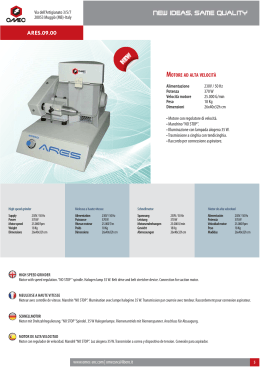
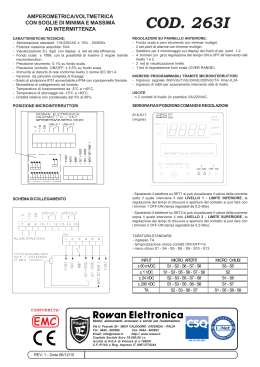
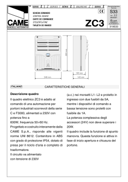
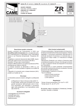
SERIE
Z | Z
SERIES
/
Z |
SÉRIE
Z |
BAUREIHE
SERIE
Z
Documentazione
Tecnica
S19
SCHEDA COMANDO
CONTROL BOARD
CARTE DE COMMANDE
STEUERPLATINE
TARJETA DE MANDO
rev.
1.3
02/2001
ZBX7
CANCELLI AUTOMATICI
© CAME
CANCELLI
AUTOMATICI
319S19
F U S .A C C E S S O R I1 A
F U S IB IL I
O N
1
T .C .A .
2
3
4
1
2
A F
L IN E A 5 A
3
4
5
6
7
8
9
1 0
A P .P A R Z .
Q U A D R O C O M A N D O
Z B X 7
ITALIANO
CARATTERISTICHE GENERALI
Descrizione scheda
Sicurezza
La scheda comando ZBX7 è adatta
al comando di automazioni scorrevoli alimentati a 230V monofase
della serie BX-A/BX-B.
La scheda va inserita e fissata nel
contenitore porta-schede del
motoriduttore (vedi descrizione
montaggio a pag.12), ed alimentata
con una tensione di 230V (a.c.) nei
morsetti L1 e L2.
É protetta in ingresso con due
fusibili da 5A, mentre i dispositivi di
comando a bassa tensione (24V)
sono protetti con fusibile da 1A.
La potenza complessiva degli accessori (24V) non deve superare i
20W.
Le fotocellule possono essere
collegate e predisposte per:
- Riapertura in fase di chiusura (2C1), le fotocellule rilevando un
ostacolo durante la fase di chiusura
del cancello, provocano l'inversione
di marcia fino alla completa apertura;
- Stop parziale, arresto del cancello
se in movimento con conseguente
predisposizione alla chiusura automatica (2-C3);
- Stop totale (1-2), arresto del cancello con l'esclusione del ciclo di
chiusura automatica, per riprendere
il movimento del cancello, agire
sulla pulsantiera o sul radiocomando;
-1-
ENGLISH
GENERAL CHARACTERISTICS
Description of control panel
The ZBX7 control board is used as a
remote control for BX-A/BX-B series
230V single-phase automated sliding
gates.
The board is introduced and fixed in
place in the gearmotor's circuit board
holder (see assembly description on
page 12), at 230V (a.c.) in terminals L1
and L2.
The inlet is protected with two 5A fuses,
while the low voltage (24V) control
devices are protected with a 1A fuse.
The accessorie's total capacity (24V)
should not exceed 20W.
Safety
Photocells can be connected to obtain:
- Re-opening during closure (2-C1), if
the photocells identify an obstacle while
the gate is closing, they will reverse the
direction of movement until the gate is
completely open;
- Partial stop, shutdown of moving gate,
with activation of an automatic closing
cycle (2-C3);
- Total stop (1-2), shutdown of gate
movement without automatic closing; a
pushbutton or radio remote control must
be actuated to resume movement).
N.B: If an NC safety contact (2-C1, 2C3, 1-2) is opened, the LED (pag.14
-n°10) will flash to indicate this fact;
-4-
-Obstacle presence detection. When the
motor is stopped (gate is closed, open
or half-open after an emercency stop
command), the transmitter and the
control pushbutton will be deactivated if
an obstacle is detected by one of the
safety devices (for example, the
photocells);
Accessories which can be connected
to this unit
- Item. 001B4336 optical reader, detects
obstacles during the gate's movement;
during the opening phase, the gate
stops and then begins a closing
movement after the automatic closure
count, whilst during closure the direction
of movement is inverted.
Warning: during closure, if obstacles are
detected three times consecutively, the
gate will remain open and automatic
closure will be discontinued. To resume
the gate's movement, use the pushbutton panel or the remote control;
- Cycle lamp. The lamp which lights the
manoeuvring zone: it remains lit from
the moment the doors begin to open
until they are completely closed
(including the time required for the
automatic closure). In case automatic
closure is not enabled, the lamp remains
lit only during movement.
The function of the cycle lamp is
obtained in output W-E1 only if dip
switch numbers: 1 “automatic closing”
and No. 6 “detect obstacle presence”
are set to ON (see page 16).
Other functions
- Automatic closing. The automatic
closing timer is automatically activated
at the end of the opening cycle. The
preset, adjustable automatic closing
time is automatically interrupted by the
activation of any safety system, and is
deactivated after a STOP command or
in case of power failure;
- Partial opening. Gate opening for
passage on foot is activated by
connecting to the 2-3P terminal blocks
and it can be adjusted by the AP.PARZ.
trimmer. By using this function,
automatic closure varies as follows:
1) Dip 1 ON - Automatic closure
activated.
-after a partial opening, the closure time
does depend on any adjustment of the
TCA trimmer.
2) Dip 1 OFF - Automatic closure
deactivated.
- If the TCA trimmer is set to the
minimum, after a partial opening,
automatic closure counting does not
begin;
- If the TCA trimmer is set to the
maximum, after a partial opening,
closing time is set to 8 seconds.
- "Operator present". Gate operates only
when the pushbutton is held down (the
radio remote control system is
deactivated);
- Slowing at the limit switch.
Only works with the optical reader on.
After every opening and closing of the
safety door or after restoring the
voltage, the slowing function is active
from the 2nd command onwards.
- Pre-flashing. After an opening or
closing command, the flasher connected
to the W-E1 flashes for 5 seconds
before beginning the procedure;
- Closing command. Function of closing
the gate only, with a wireless control
device connected to contact 2-7, set dip
1 to ON (4-way module), see page 22;
- Opening command. Function of
opening the gate only, with a wireless
control device connected to contact 23P, set dip 2 to ON (4-way module), see
page 22;
-Type of command:
-Open-stop-close-stop by button and
transmitter;
-Open-close by button and transmitter;
-Open only by transmitter.
Adjiustments
- Automatic closure time;
- Partial opening time.
FUNCTION AVAIABLE ONLY FOR GATES
WEIGHING UP TO
300 KG, OTHERWISE IT
MUST BE DISACTIVATED
The gate slows down before the
opening or closing movement is
completed.
IMPORTANT: Shut off the mains power
before servicing the inside of the unit.
-5-
DESCRIZIONE DI MONTAGGIO - ASSEMBLY DESCRIPTION - DESCRIPTION DU MONTAGE
MONTAGEANLEITUNG - DESCRIPTIÓN DEL MONTAJE
ITALIANO
-Aprire lo sportello accesso sblocco, allentare
la vite del coperchio quadro comando e levarlo (1).
-Rimuovere il copri-scheda dalla piastra di
supporto quadro comando (2).
-Agganciare e fissare la scheda ZBX7 nella
piastra di supporto quadro comando con le viti
predisposte (3).
-Riposizionare il supporto copri-schede (4).
-Procedere al collegamento elettrico, fissare il
coperchio del quadro comando e chiudere lo
sportello accesso blocco (5).
1
ENGLISH
-Open the release access door, loosen the
screws of the control panel cover and lift it (1).
-Remove the circuit board cover from the
control panel support plate (2).
-Hook and fix the ZBX7 board to the control
panel support plate with the appropriate screws
(3).
-Reposition the circuit board cover support
(4).
-Proceed with the electric connection, replace
the control panel cover and close the release
access door (5).
FRANÇAIS
-Ouvrir le volet d'accès au déblocage,
desserrer la vis du couvercle de l'armoire de
commande et l'enlever (1).
-Enlever le protège-carte de la plaque qui
soutient l'armoire de commande (2).
-12-
2
-Accrocher et fixer la carte ZBX7 dans la
plaque qui soutient l'armoire de commande
avec les vis prévues à cet effet (3).
-Remettre le support protège-cartes (4).
-Effectuer le branchement électrique, fixer le
couvercle de l'armoire de commande et
refermer le volet d'accès au blocage (5).
3
DEUTSCH
-Öffnen Sie die Klappe, die Zugriff auf die
Schalttafel gibt. Lösen Sie die Schrauben von
der Abdeckung der Schalttafel und nehmen
Sie die Abdeckung ab (1).
-Nehmen Sie die Kartenabdeckung von der
Halterungsplatte der Schalttafel ab (2).
-Stecken Sie die Karte ZBX7 in die
Halterungsplatte der Schalttafel und befestigen
Sie die mit den entsprechenden Schrauben
(3).
-Bringen Sie die Kartenabdeckung wieder an
(4).
-Führen Sie den Stromanschluß durch.
Bringen Sie dann die Abdeckung wieder auf
der Schalttafel an und schließen Sie die Klappe
wieder (5).
4
ESPANIOL
-Abra la puerta de acceso al desbloqueo,
afloje el tornillo de la tapa del cuadro de
mando y quítelo (1).
-Quite el cubretarjeta de la placa de soporte
del cuadro de mando (2).
-Enganche y fije la tarjeta ZBX7 a la placa de
soporte del cuadro de mando, con los tornillos
suministrados (3).
-Vuelva a colocar el soporte cubretaryeta (4).
-Realice la conexión eléctrica, fije la tapa del
cuadro de mando y cierre la puerta de acceso
al desbloqueo (5).
5
-13-
SCHEDA BASE - MOTHERBOARD - CARTE BASE - GRUNDPLATINE - TARJETA BASE
1
3
L IN E A 5 A
8
7
1
11
T .C .A .
2
3
4
1
4
Q U A D R O C O M A N D O
Z B X 7
ITALIANO
1
2
3
4
5
6
7
8
9
10
11
-14-
2
3
4
5
6
7
8
9
1 0
10
A P .P A R Z .
6
9
11
O N
A F
2
F U S .A C C E S S O R I1 A
F U S IB IL I
5
11
COMPONENTI PRINCIPALI
Morsettiere di collegamento
Fusibili di linea 5A
Fusibile accessori 1A
Pulsanti di memorizzazione codice radio
Trimmer di regolazione apertura parziale
Trimmer di regolazione tempo di chiusura automatica
Selettore funzioni a 4 dip (vedi pag.22)
Selettore funzioni a 10 dip (vedi pag.19)
Innesto scheda radiofrequenza (vedi tabella)
LED segnalazione
Asolature per fissaggio scheda
ENGLISH
1
2
3
4
5
6
7
8
9
10
11
Terminal block for external conections
Line fuse, 5A
Fuse on accessory power line, 1A
Radio-code save buttons
Trimmer for adjustment operating time
Trimmer for adjustment automatic closing
4-dip function switch (see pag.22)
10-dip function switch (see pag.19)
Socket AF radiofrequency board (see table)
Signal LED
Grooves for board positioning
FRANÇAIS
1
2
3
4
5
6
7
8
9
10
11
HAUPTKOMPONENTEN
AnschlußKlemmenleiste
Hauptsicherung 5A
Zubehör-Sicherung 1A
Knöpfe zum Abspeicher der Radiocodes
Trimmer zur Einstellung Laufzeit
Trimmer zur Einstellung der Schließautomatik
Wählschalter für Funktionen mit 4 Dip (sehen S.22)
Wählschalter für Funktionen mit 10 Dip (sehen S.19)
Steckanschluß Funkfrequenze-Platine AF (sehen Tabelle)
LED Kontrolleuchte zur Anzeige
Lochung für die Befestigung der Karte
ESPANOL
1
2
3
4
5
6
7
8
9
10
11
PRINCIPAUX COMPOSANTS
Plaque à bornes de connexion
Fusible de ligne 5A
Fusible accessoires 1A
Boutons-poussoir mémorisation code radio
Trimmer de réglage temps de fonctionnement
Trimmer de réglage fermeture automatique
Selecteur de fonctions à 4 interrupteurs à positions multiples (voir pag.22)
Selecteur de fonctions à 10 interrupteurs à positions multiples (voir pag.19)
Branchement carte radiofréquence AF (voir tableau)
LED de signalisation
Fentes pour fixer la carte
DEUTSCH
1
2
3
4
5
6
7
8
9
10
11
MAIN COMPONENTES
PRINCIPALES COMPONENTES
Caja de bornes para las conexiónes
Fusible de línea 5A
Fusible accesorios 1A
Teclas de memorización del código radio
Trimmer de regulación tiempo trabajo
Trimmer de regulación tiempo cierre automático
Selector de funciones con 4 dip (vedas pág.22)
Selector de funciones con 10 dip (vedas pág.19)
Conexión tarjeta radiofrecuencia AF (vedas tabla)
LED de señal
Perforaciones para fijación de la tarjeta
-15-
COLLEGAMENTI ELETTRICI - ELECTRICAL CONNECTIONS - BRANCHEMENTS ÉLECTRIQUES
ELEKRISCHE ANSCHLÜSSE - CONEXIONES ELÉCTRICAS
L1 L2
L1
L2
U
W
V
U V W E1 10 11 1
2 3P 7 C1 C3
E D
FA FC F B1 B2
Alimentazione 230V (a.c.)
230V (a.c.) power input
Alimentation 230V (c.a.)
Stromversorgung 230V (Wechselstrom)
Alimentación 230V (a.c.)
Motore monofase 230V (a.c.)
230V (a.c.) single-phase motor
Moteur monophasé 230V (c.a.)
Einphasenmotor 230V (Wechselstrom)
Motor monofásico 230V (a.c.)
Uscita 230V (a.c.) in movimento
(es.lampeggiatore - max. 25W)
230V (a.c.) output in motion
(e.g. flashing light - max. 25W)
Sortie 230V (c.a.) en mouvement
(ex. branchement clignotant - max. 25W)
Ausgang 230V (Wechselstrom) in Bewegung
(z.B. Blinker-Anschluß - max. 25W)
Salida de 230V (a.c.) en movimento
(p.ej. lámpara intermitente - max. 25W)
U V W E1
W
E1
Uscita 230V (a.c.) lampada ciclo - max. 60W
230V (a.c.) max.60W - cycle lamp
Sortie 230V (c.a.) lampe cycle - max. 60W
Ausgang 230V (Wechselstrom)
Betriebszyklus-Anzeigeleuchte - max.60W
Salida de 230V (a.c.) lámpara ciclo - max.60W
ON
1 2 3
-16-
4
5 6
7
8
9 10
U V W E1
10
11
1
2
2
3P
2
7
11
FC
11
FA
Alimentazione accessori 24V (a.c.) max. 20W
24V (a.c.)Powering accessories (max 20W)
Alimentation accessoires 24V (c.a.) max. 20W
Zubehörspeisung 24V (Wechselstrom) max. 20W
Alimentación accesoios 24V (a.c.) max. 20W
Pulsante stop (N.C.)
Pushbutton stop (N.C.)
Bouton-poussoir arrêt (N.F.)
Stop-Taste (N.C.)
Pulsador de stop (N.C.)
Pulsante per apertura parziale (N.O.)
Button (N.O.) for partial opening
Bouton-poussoir (N.O.) pour ouverture partial
Taste (Arbeitskontakt) für TeilÖffnung
Pulsador (N.O.) para apertura parcial
Contatto radio e/o pulsante per comando
(vedi dip pag.19-22)
Contact radio and/or button for control
(see dip pag.19-22)
Contact radio et/ou poussoir pour commande
(voir dip pag.19-22)
Funkkontakt und/oder Taste Steuerart
(sehen Dip Seite 19-22)
Contacto radio y/o pulsador para mando
(vedas dip pág.19-22)
Lampada spia (24V-3W max.) "cancello aperto"
(24V-3W max.) "gate-opened" signal lamp
Lampe-témoin (24V-3W max.) "portail ouverture"
Signallampe (24V-3W max.) "Tor Öffnen"
Lámpara indicadora (24V-3W max.) "puerta abierta"
Lampada spia (24V-3W max.) "cancello chiuso"
(24V-3W max.) "gate-closed" signal lamp
Lampe-témoin (24V-3W max.) "portail fermeture"
Signallampe (24V-3W max.) "Tor Schließen"
Lámpara indicadora (24V-3W max.) "puerta cierre"
-17-
2
C1
2
C3
B1
B2
F
FA
F
FC
Contatto (N.C.) di «riapertura durante la chiusura»
Contact (N.C.) for «re-opening during the closing»
Contact (N.F.) de «réouverture pendant la fermeture»
Kontakt (Ruhekontakt) «Wiederöffnen beim Schliessen»
Contacto (N.C.) para la «apertura en la fase de cierre»
Contatto (N.C.) di «stop parziale»
Contact (N.C.) for «partial stop»
Contact (N.F.) de «stop partiel»
Kontakt (Ruhekontakt) «Teilstop»
Contacto (N.C.) para la «parada parcial»
Uscita contatto (N.O.) Portata contatto: 5A - 24V d.c.
Contact output (N.O.) Resistive load: 5A - 24V d.c.
Sortie contact (N.O.) Portée contact: 5A - 24V c.c.
Ausgang Arbeitskontakt Stromfestigkeit: 5A-24V Gleichstrom
Salida contacto (N.O.) Carga resistiva: 5A - 24V d.c.
Collegamento finecorsa apre
Connection limit switch opens
Connexion fin de course ouverture
Anschluß Endschallter Öffnung
Conexión fin de carrera apertura
Collegamento finecorsa chiude
Connection limit switch closes
Connexion fin de course fermeture
Anschluß Endschallter Schließung
Conexión fin de carrera cierre
Collegamento antenna
Antenna connection
Connexion antenne
Antennenanschluß
Conexión antena
-18-
SELEZIONI FUNZIONI - SELECTION OF FUNCTIONS - SÉLECTION FONCTIONS
FUNKTIONSWAHL- SELECCIÓN DE LAS FUNCIONES
FUS. ACCESSORI 1A
DIP-SWITCH 10 VIE / 10-WAY DIP-SWITCH / DIP-SWITCH 10 VOIES
ZEHNWEG-DIP-SWITCH / DIP-SWITCH 10 VÍAS
ON
ON
1 2 3 4
5 6
7 8 9 10
1
2
3
4
5
6
7
8
9 10
ON
OFF
ITALIANO
1 ON
2 ON
Chiusura automatica attivata; (1 OFF - disattivata)
"Apre-stop-chiude-stop" con pulsante (2-7) e radiocomando (scheda AF
inserita) attivata;
2 OFF "Apre-chiude" con pulsante (2-7) e radiocomando (scheda AF inserita)
attivata;
3 ON "Sola apertura" con radiocomando (scheda AF inserita) attivata;
(3 OFF - disattivata)
4 OFF "Uomo presente" (esclude il funzionamento del radiocomando) disattivata;
(4 ON - attivata)
5 ON Prelampeggio attivato; (5 OFF - disattivato)
6 ON Rilevazione di presenza ostacolo attivata; (6 OFF - disattivata)
7 OFF Riapertura in fase di chiusura attivata; con dispositivo di sicurezza collegato
ai morsetti 2-C1, (se non viene utilizzato il dispositivo, selezionare il dip in
ON)
8 OFF Stop parziale attivata; con dispositivo di sicurezza collegato ai morsetti 2-C3,
(se non viene utilizzato il dispositivo, selezionare il dip in ON)
9 OFF Stop totale attivata con dispositivo di sicurezza collegato ai morsetti 1-2, (se
non viene utilizzato il dispositivo, selezionare il dip in ON)
10 OFF Rallentamenti a finecorsa attivati (solo per cancelli fino a 300 Kg); con
lettore ottico installato (10 ON- disattivati)
NOTA: le selezioni vanno eseguite a motore fermo in posizione di chiusura.
-19-
ENGLISH
1 ON
Automatic closure activated;
(1 OFF-deactivated)
2 ON "Open-stop-close-stop" with
button (2-7) and radio control
(AF board inserted) activated;
2 OFF "Open-close" with button (2-7)
and radio control (AF board
inserted) activated;
3 ON "Only opening" with radio control
(AF board inserted) activated;
(3 OFF-deactivated)
4 OFF "Operator present" operation
(radio remote control is
deactivated when function is
selected) deactivated;
(4 ON -activated)
5 ON Pre-flashing activated;
(5 OFF-deactivated)
6 ON Obstacle detection device
activated; (6 OFF-deactivated)
7 OFF Re-opening in closing phase
activated; connect the safety
device on terminals 2-C1, (if not
used, set the dip-switch to ON)
8 OFF Partial stop activated; connect
the safety device on terminals 2C3, (if not used, set the
dip-switch to ON)
9 OFF Total stop activated; connect
the safety device on terminals 12, (if not used, set the dip-switch
to ON)
10 OFF Limit switch slowing activated
(only for gates weighing up to
300 kg); connect the optical
reader (10 ON-deactivated)
NOTE: the selections should be carried
out with the motor off in the closed
position.
-20-
FRANÇAIS
1 ON
Fermeture automatique activée;
(1 OFF-désactivée)
2 ON "Ouvre-stop-ferme-stop" avec
bouton (2-7) et commande-radio
(carte AF insérée) activée;
2 OFF "Ouvre-ferme" avec bouton (2-7)
et commande-radio (carte AF
insérée) activée;
3 ON "Soulement ouverture" avec
commande-radio (carte AF
insérée) activée;
(3 OFF-désactivée)
4 OFF "Homme mort" (exclut la fonction
radiocommande) désactivée;
(4 ON-activée)
5 ON Preclignotement activée;
(5 OFF-désactivée)
6 ON Dispositif de détection d'obstacle
activée; (6 OFF-désactivée)
7 OFF Réouverture en phase de
fermeture activée; relier le
dispositif de sécuritè aux bornes
2-C1; (s'il n'est pas utilisé,
positionner l'interrupteur à
positions multiples sur ON)
8 OFF Stop partiel activée; relier le
dispositif de sécurite aux bornes
2-C3, (s'il n'est pas utilisé,
positionner l'interrupteur à
positions multiples sur ON)
9 OFF Stop total activée relier le
dispositif de sécurite aux bornes
1-2, (s'il n'est pas utilisé,
positionner l'interrupteur à
positions multiples sur ON)
10 OFF Ralentissement en fin de
course activée (uniquement
pour portails jusqu'à 300 Kg);
relier lecteur optique (10 ONdésactivée)
NOTE: les sélections doivent être
effectuées en position de fermeture
quand le moteur est arrête.
FUS. ACCESSORI 1A
DIP-SWITCH 4 VIE / 4-WAY DIP-SWITCH / DIP-SWITCH 4 VOIES
VIERWEG-DIP-SWITCH / DIP-SWITCH 4 VÍAS
1
1 2 3 4
ITALIANO
1 ON "Sola chiusura" con dispositivo di comando collegato sul contatto 2-7
attivata;
1 OFF "Apre-chiude" con dispositivo di comando collegato su 2-7 (vedi dip 2 del
selettore funzioni a 10 vie) attivata;
2 ON "Sola apertura" con dispositivo di comando collegato sul contatto 2-3P
attivata;
2 OFF Apertura parziale attivata;
3 OFF Lettore ottico attivato; art. 001B4336
installato (3ON - disattivato);
4 ON Non connesso
NOTA: le selezioni vanno eseguite a
motore fermo in posizione di chiusura.
FRANÇAIS
1 ON "Uniquement fermeture" avec dispositif
de commande branché sur le contact
2-7 activée;
1 OFF "Ouvre-ferme" avec dispositif de
commande branché sur le contact 2-7
(voir commutateur à bascule 2 du
sélecteur des fonctions à 10 voies)
activée;
2 ON "Uniquement ouverture" avec dispositif
de commande branché sur le contact
2-3-P activée;
2 OFF Ouverture partielle activée;
3 OFF Lecteur optique activée; art. 001B4336
branché (3ON - dèsactivée);
4 ON Non connecté
NOTE:les sélections doivent être effectuées
en position de fermeture quand le moteur est
arrête.
-22-
2
3
4
ON
OFF
ENGLISH
1 ON "Closing only" with a wireless control
device connected to the 2-7 contact
activated;
1 OFF "Open-close" with a wireless control
device connected to the 2-7 contact
(see the 10-way function selector dip 2)
activated;
2 ON "Opening only" with a wireless control
device connected to the 2-3P contact
activated;
2 OFF Partial opening activated;
3 OFF Optical reader activated; item.
001B4336 connected (3ON desactivated);
4 ON Not connected
NOTE:the selections should be carried out with
the motor off in the closed position.
DEUTSCH
1 ON "Nur Schlißen" mit an Kontakt 2-7
angeschlossener Steuervorrichtung
aktiviert;
1 OFF "Öffnen-Schließen" mit an Kontakt 2-7
angeschlossener Steuervorrichtung
aktiviert (siehe Dip-Schalter 2 vom 10Weg Funktionswählschalter);
2 ON "Nur Öffnen" mit an Kontakt 2-3P
angeschlossener Steuervorrichtung
aktiviert;
2 OFF Teilweises Öffnen aktiviert;
3 OFF Optischer Leser aktiviert; art. 001B4336
angeschlossener (3ON - deaktiviert);
4 ON nicht angeschlossen
HINWEIS:Die Schalter nur bei abgeschaltetem
Motor und geschlossenem Tor betätigen.
ESPANOL
1 ON "Sólo cierre" con dispositivo de mando conectado en el contacto 2-7 activo;
1 OFF "Abrir-cerrar" con dispositivo de mando conectado en 2-7 (véase dip 2 del
selector de funciones de 10 vías) activo;
2 ON "Sólo apertura" con dispositivo de mando conectado en el contacto 2-3P activo;
2 OFF Apertura parcial activo;
3 OFF Lector óptico activo; art. 001B4336 conectado (3ON - desactivado);
4 ON No conectado
NOTA: las selecciones se realizan con el motor parado en posición de cierre.
REGOLAZIONI - ADJUSTMENTS - RÉGLAGES - EINSTELLUNGEN - REGULACIONES
ITALIANO
FUS. ACCESSORI 1A
T .C .A .
T.C.A.
A P .P A R Z .
AP.PARZ.
REGOLAZIONE TRIMMERS
TRIMMERS ADJUSTMENT
RÉGLAGE TRIMMERS
EINTELLUNG TRIMMERS
Trimmer T.C.A. = Regolazione tempo
di chiusura automatica da un minimo di
0 secondi a un massimo di 120 secondi.
Trimmer AP.PARZ. = Regolazione di
apertura parziale da un minimo di 0
secondi a un massimo di 16 secondi.
REGULACIÓN TRIMMERS
ENGLISH
Trimmer T.C.A. = Adjusts automatic
closing time from a minimum of 0
seconds to a maximum of 120 seconds.
Trimmer AP.PARZ. = Adjusts partial
opening from a minimum of 0 seconds
to a maximum of 16 seconds.
DEUTSCH
Trimmer T.C.A. = Timer, auf dem die
Verzögerung für das automatische
Schließen mit mindestens 0 Sekunden
und höchstens 120 Sekunden
eingestellt werden kann.
Trimmer AP.PARZ. = Timer, auf dem
die Verzögerung für das Teilöffnung mit
mindestens 0 Sekunden und höchstens
16 Sekunden eingestellt werden kann.
FRANÇAIS
Trimmer T.C.A. = Réglage du temps de
fermeture automatique d'un minimum de
0 secondes à un maximun de 120
secondes.
Trimmer AP.PARZ. = Réglage d'ouverture partial d'un minimum de 0
secondes à un maximun de 16
secondes.
ESPANOL
Trimmer T.C.A. = Regulación del
tiempo de cierre automático, desde un
mínimo de 0 segundos hasta un
máximo de 120 segundos.
Trimmer AP.PARZ. = Regulación de
apertura parcial, desde un mínimo de 0
segundos hasta un máximo de 16
segundos.
-23-
COLLEGAMENTO PER 2 MOTORI ABBINATI - CONNECTIONS FOR 2 COMBINED MOTORS
CONNEXIONS POUR 2 MOTEURS ACCOUPLÉS
ANSCHLUSSE FÜR 2 PARALLELGESCHALTETEN MOTOREN - CONEXIÓN PARA 2 MOTORES ACOPLADOS
A
B
1
Nel caso d'installazione di due motori
abbinati, procedere nel seguente modo:
- Coordinare il senso di marcia dei
motoriduttori "A" e "B", modificando la
rotazione del motore "B" (vedi collegamento finecorsa);
- Assicurarsi che sia inserito il ricevitore
radio (AF) sul quadro del motore "A" (1);
- Su entrambi i quadri devono essere
fatte le stesse regolazioni e funzioni (2);
- Eseguire i collegamenti elettrici tra le
morsettiere del quadro "A" e "B" come
da «Fig. A»;
- Il pulsante di apertura parziale (2-3P)
va collegato sulla morsettiera del quadro
del motore interessato;
-24-
C .A .
SCHED
A BASE MO
TORE "A"
SCHEDA
MOT
MOTOR "A" MOTHERBOARD
CAR
TE DE BASE MO
TEUR "A"
CARTE
MOTEUR
BASISKARTE MOTOR "A"
TARJET
A BASE MO
TOR «A»
ARJETA
MOT
A
FUS. ACCESSORI 1A
2
1 2 3 4
REGOLAZIONI
SETTING
RÉGLA
GES
RÉGLAGES
EINSTELLUNGEN
REGULA
CIONES
REGULACIONES
B
FUNZIONI
FUNCTIONS
FONCTIONS
FUNKTIONEN
FUNCIONES
FUS. ACCESSORI 1A
N.B. Per comandare le automazioni con
l'utilizzo del radiocomando occorre,
memorizzare il codice del trasmettitore
sul canale CH2 della scheda base del
motore "A" (vedi programmazione
radiocomando). Dopo aver memorizzato
il codice, collegare i contatti B1-B2 con
2-7. Il comando di apertura sarà di tipo
«apre-chiude», «apre-stop-chiude-stop»
o «solo apertura», secondo la disposizione dei dip 2-3, selezionati su entrambe le schede.
SCHED
A RADIOFREQUENZA "AF"
SCHEDA
"AF" RADIO FREQUENCY BOARD
CAR
TE FREQUENCE RADIO "AF"
CARTE
RADIOFREQUENZKARTE «AF»
TARJET
A RADIOFRECUENCIA
ARJETA
A F 4 3 S /S M
ITALIANO
1 2 3 4
ENGLISH
In case two combined motors are installed, proceed in the following manner:
- Coordinate the direction of the "A" and "B" gearmotors, modifying the rotation of
motor "B" (see limitswitch setting);
- Make sure that the (AF) radio receiver is connected to the motor "A" control panel
(1);
- The same settings and functions must be made on both control panels (2).
- Make the necessary electric connections between the terminal boards of the "A"
and "B" panels as in «Fig. A»;
- The partial aperture button (2-3P) should be connected to the terminal board of the
corresponding motor control panel;
N.B. To control the automatic gate with the wireless control, it is first necessary to
memorise the transmitter code on channel CH2 of the motor "A" motherboard (see
programming remote control). After memorising the code, connect contacts B1-B2
with 2-7. The opening command will be of type «open-close», «open-stop-closestop» or «open only», depending on the dip 2-3 settings, selected on both boards.
FRANÇAIS
Pour installer deux moteurs accouplés, procéder comme suit:
- Coordonner le sens de marche des motoréducteurs "A" et "B" en modifiant la
rotation du moteur "B" (voir programmation interrupteur de fin de course);
- Contrôler si le récepteur radio (AF) est branché sur le carte de base du moteur "A"
(1);
- Les mêmes réglages et fonctions doivent être effectués sur les deux tableaux (2).
- Effectuer les branchements électriques entre les plaques à borne du tableau "A" et
"B", comme indiqué sur la «Fig. A»;
- Brancher le bouton d’ouverture partielle (2-3P) à la plaque à bornes du tableau du
moteur intéressé;
N.B. Pour commander les automatismes à l'aide de la radiocommande, mémoriser le
code de l'émetteur sur le canal CH2 de la carte de base du moteur "A" (voir
programmation commande radio). Après avoir mémorisé le code, brancher les
contacts B1-B2 à 2-7. La commande d'ouverture sera du type «ouvre-ferme», «ouvrearrêt-ferme-arrêt» ou «uniquement ouverture», selon la disposition des commutateurs
à bascule 2-3 sélectionnés sur les deux cartes.
-25-
FIG. A
ABB. A
Morsettiera del quadro motore «A»
Terminal board of the "A" motor control panel
Plaque à bornes du tableau du moteur «A»
Klemmbrett der Schalttafel vom Motor «A»
Tablero de bornes del cuadro motor «A»
10 11 1 2 3P 7 C1 C3
B1 B2
Morsettiera del quadro motore «B»
Terminal board of the "B" motor control panel
Plaque à bornes du tableau du moteur «B»
Klemmbrett der Schalttafel vom Motor «B»
Tablero de bornes del cuadro motor «B»
10 11 1 2 3P 7 C1 C3
(1-2)
(2-7)
(2-3P)
(2-C 1)
(2-C 3)
-27-
COLLEGAMENTO FINECORSA - LIMIT SWITCH CONNECTIONS - BRANCHEMENT DE COURSE
ENDAUSSCHALTER-ANSCHLUSS - CONEXION FINAL DE CARRERA
ITALIANO
Gruppo motore-finecorsa già collegati per montaggio a sinistra vista interna.
Per eventuale montaggio a destra:
- invertire FA-FC dei finecorsa sulla morsettiera;
- invertire le fasi U-V del motore sulla morsettiera.
ENGLISH
The motor and limit switch unit are wired at the factory for mounting on the left-hand
side of the gate (as seen from the inside). If right-hand installation is desired:
- invert limit switch connections FA-FC on the terminal block;
- invert motor phase connections U-V on the terminal block.
FRANÇAIS
Groupe moteur-fins de course déjà branchés pour le montage à gauche - vue de
l'intérieur.
Pour un éventuel montage à droite:
- inverser FA-FC des fins de course sur la plaque à bornes;
- inverser les phases U-V du moteur sur la plaque à bornes.
DEUTSCH
Das Motor-Anschlag-Aggregat schon für die Montage auf der linken Seite
angeschlossen, interne Ansicht.
Für eine eventuelle Montage auf der rechten Seite:
- die Öffnungs- und Schließungsphasen auf dem Klemmbrett invertieren;
- die U-V Phasen des Motors auf dem Klemmen tauschen.
ESPANOL
Grupo motor-fin de carrera ya conectados para el montaje a la izquierda vista interior.
Para el eventual montaje a la derecha:
- invertir FA-FC de los fines de carrera en el cuadro de bornes;
- invertir las fases U-V del motor en el cuadro de bornes.
NC
NC
F
U W V
Gruppo finecorsa
Limit switch unit
Groupe fins de course
Anschlag-Gruppe
Grupo fin de carrera
-28-
Motore monofase 230V
230V single-phase motor
Moteur monophasé 230V
Einphasiger Motor 230V
Motor monofásico de 230V
FC
F
U W V
COM
COM
M
FA
NC
FC
NC
FA
M
Motore monofase 230V
Gruppo finecorsa
Limit switch unit
230V single-phase motor
Groupe fins de course Moteur monophasé 230V
Einphasiger Motor 230V
Anschlag-Gruppe
Grupo fin de carrera Motor monofásico de 230V
LIMITATORE DI COPPIA MOTORE / MOTOR TORQUE LIMITER / LIMITEUR DE COUPLE MOTEUR
DREHMOMENTBEGRENZER DES MOTORS /LIMITADOR DE PAR MOTOR
ITALIANO
L2T 1
2 3 4 L1T
0 12 24
Per variare la coppia motrice, spostare il
faston indicato (con filo di colore nero)
su una delle 4 posizioni; 1 min. - 4 max
ENGLISH
To vary the motor torque, move the
indicated faston to one of the four
positions: 1=min, 4=max
FRANÇAIS
L1T L2T CT
0 12 24
FUS.ACCESSORI 1A
Pour varier le couple du moteur,
déplacer le connecteur indiqué sur l'une
des 4 positions; 1 min. - 4 max.
DEUTSCH
Zur Änderung des Motor-Drehmoments
den angegebenen Faston auf eine der 4
Stellungen positionieren: 1 min. - 4 max.
ESPANIOL
Para variar el par motor, desplazar el
faston indicado hasta una de las 4
posiciones; 1 mín. - 4 máx.
-29-
NOTE - NOTE - NOTE - HINWEIS - NOTA
ASSISTENZA T ECNICA
NUMERO VERDE
800 295830
CANCELLI AUTOMATICI
SISTEMA QUALITÀ
CERTIFICATO
WEB
www.came.it
E-MAIL
[email protected]
CAME CANCELLI AUTOMATICI S.P.A.
DOSSON DI C ASIER (TREVISO)
(+39) 0422
(+39) 0422 490944
CAME LOMBARDIA S.R.L.___COLOGNO M. (MI)
(+39) 02 26708293
(+39) 02 25490288
CAME SUD S.R.L. _________________NAPOLI
(+39) 081 752445
(+39) 081 7529109
CAME (AMERICA) L.L.C._________MIAMI (FL)
(+1) 305 5930227
(+1) 305 5939823
CAME AUTOMATISMOS S.A_________MADRID
(+34) 091 5285009
(+34) 091 4685442
CAME BELGIUM____________LESSINES
(+32) 068 333014
(+32) 068 338019
CAME FRANCE S.A.___NANTERRE CEDEX (PARIS)
(+33) 01 46130505
(+33) 01 46130500
CAME GMBH____K ORNTAL BEI (STUTTGART)
(+49) 07 11839590
(+49) 07 118395925
CAME GMBH________S EEFELD BEI (BERLIN)
(+49) 03 33988390
(+49) 03 339885508
CAME PL SP.ZO.O_________WARSZAWA
(+48) 022 8699933
(+48) 022 6399933
CAME UNITED KINGDOM LTD___NOTTINGHAM
(+44) 01159 387200
(+44) 01159 382694
Scaricare