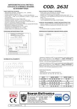
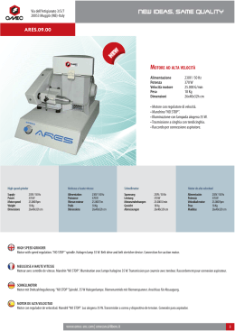
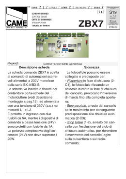
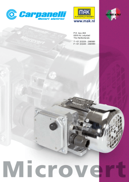
SERIE
Z | Z
SERIES
/
SÉRIE
Z |
BAUREIHE
Z |
SERIE
Z
Documentazione
Tecnica
S33
SCHEDA COMANDO
CONTROL BOARD
CARTE DE COMMANDE
STEUERPLATINE
TARJETA DE MANDO
rev.
2.2
09/2001
ZC3
319S33
320 mm
CANCELLI AUTOMATICI
©
CAME
CANCELLI
AUTOMATICI
120 mm
240 mm
ITALIANO
145 mm
CARATTERISTICHE GENERALI
Descrizione quadro
Il quadro elettrico ZC3 è adatto al
comando di una automazione per
portoni industriali scorrevoli della serie
C e F3000, alimentati a 230V con
potenza fino a
600W, frequenza 50÷60 Hz.
Progettato e costruito interamente dalla
CAME S.p.A., risponde alle vigenti
norme UNI 8612. Contenitore in ABS
con grado di protezione IP54, dotato di
presa per il riciclo d’aria e completo di
trasformatore.
Il circuito va alimentato
con tensione di 230V
(a.c.) nei morsetti L1- L2 e protetto in
ingresso con due fusibili da 5A,
mentre i dispositivi di comando a
bassa tensione sono protetti con
fusibile da 1A.
La potenza complessiva degli
accessori (24V) non deve superare i
20W.
Il quadro include la funzione di spunto
manovra. Questa funzione si attiva in
fase di inizio apertura e chiusura del
portone.
ENGLISH
GENERAL CHARACTERISTICS
Description of control panel
The ZC3 electric panel is suitable for
controlling the automation of series C
and F3000, 230V sliding industrial
gates, with up to 600W power and 5060 Hz frequency.
Wholly designed and built by CAME
S.p.A., it meets UNI 8612 regulations
in force. ABS Case with an IP54 protective level, with air recycling inlet and
transformer.
The circuit requires 230V (a.c.) at terminal blocks L1- L2 and the inlet is protected with two 5A fuses, whilst the low
voltage command devices are protected by a 1A fuse.
The accessories’ total wattage (24V)
must not exceed 20W.
The panel includes a manoeuvre pickup function. This function is activated
during the initial phase of the gate’s
opening and closing.
Safety
Photocells can be connected to obtain:
- Re-opening during closure (2-C1), if
the photocells identify an obstacle
while the gate is closing, they will
reverse the direction of movement until
the gate is completely open;
- Re-closing during opening (2-CX, see
dip n°8 to OFF - 9 to OFF), if the
photocells identify an obstacle while
-4-
the gate is opening, they will reverse
the direction of movement until the
gate is completely close;
- Partial stop, shutdown of moving
gate, with activation of an automatic
closing cycle (2-CX, dip n°8 OFF - 9
ON);
- Total stop (1-2), shutdown of gate
movement without automatic closing; a
pushbutton or radio remote control
must be actuated to resume
movement.
N.B: If an NC safety contact (2-C1, 2CX, 1-2) is opened, the LED (pag.12
-n°8) will flash to indicate this fact;
- Obstacle presence detection. When
the motor is stopped (gate is closed,
open or half-open after an emergency
stop command), the transmitter and
the control pushbutton will be
deactivated if an obstacle is detected
by one of the safety devices (for
example, the photocells);
- Safety test function. The control unit
will now check the safety system every
time an opening or closing command is
given (see p.18).
Accessories which can be
connected to this unit
- Cycle lamp. The lamp which lights the
manoeuvring zone: it remains lit from
the moment the doors begin to open
until they are completely closed
(including the time required for the
automatic closure). In case automatic
closure is not enabled, the lamp
remains lit only during movement (EEX, dip n°16 OFF - 17 ON);
-Courtesy Light. A light that illuminates
the manoeuvring zone; after an opening command, the light remains on for
a fixed time of 5 minutes and 30 seconds (E-EX, dip n°16 ON - 17 OFF);
- Open gate pilot lamp. It is a light that
indicates the sliding gate’s open
position and turns off when the gate
activates the closing end-stop.
Other functions
- Automatic closing. The automatic
closing timer is automatically activated
at the end of the opening cycle. The
preset, adjustable automatic closing
time is automatically interrupted by the
activation of any safety system, and is
deactivated after a STOP command or
in case of power failure;
-Partial opening. Opening of the gate to
allow for foot traffic; activated by
connecting to terminals 2-3P and
adjusted with the AP-PARZ. trimmer.
With this function, the automatic
closing can vary in the following way:
1) Dip 12 set to ON: after a partial
opening, the time for automatic closing
functions independently of the adjust-
ment of the TCA trimmer and of the position of Dip 1; it is set at 8 seconds.
2) Dip 12 set to OFF: after a partial
opening, the time for automatic closing
is adjustable only if Dip 1 is set to ON.
- "Operator present". Gate operates
only when the pushbutton is held down
(the radio remote control system is
deactivated);
- Pre-flashing. After an opening or
closing command, the flasher
connected to the W-E flashes for 5
seconds before beginning the procedure;
-Type of command:
-Open-stop-close-stop by button and
transmitter;
-Open-close by button and transmitter;
-Open only by transmitter.
Adjiustments
- Operating time;
- Automatic closure time;
- Partial opening time.
Caution! Disconnect the unit
from the main power lines before
carrying out any operation inside the
unit.
-5-
SCHEDA BASE - MOTHERBOARD - CARTE BASE - GRUNDPLATINE - TARJETA BASE
12
2
12
24
3
4
Nota: collegare i fili neri che
fuoriescono dalla scheda sui
connettori del condensatore.
SPUNTO
FRENO
1
0
6
5
T.L.
3
7
T.C .A.
8
9
AP.PAR Z.
FUS.ACC ESSORI 1A
1
10
ON
ON
4
2
3
4
5
6
7
8
9
10
11 12 13 14 15 16 17 18 19 20
11
AF
QUADRO COMANDO
ZC3
FUS.LINEA5A
2
ITALIANO
1
2
3
4
5
6
7
8
9
10
11
12
-12-
1
NB: connect the black wires coming
out of the board to the condenser’s
connectors.
Note: connecter les fils noirs qui
sortent de la carte sur les
connecteurs du condensateur.
Hinweis: Die schwarzen Kabel, die
von der Karte wegführen, an die
Verbinder am Kondensator
anschließen.
Nota: conectar los hilos negros
que salen de la tarjeta en los
conectores del condensador.
COMPONENTI PRINCIPALI
Morsettiere di collegamento
Fusibili di linea 5A
Fusibile accessori 1A
LED segnalazione tensione presente a 24V
Trimmer di regolazione tempo lavoro
Trimmer di regolazione tempo di chiusura automatica
Trimmer di regolazione apertura parziale
LED segnalazione
Pulsanti memorizzazione codice
Selettore funzioni (vedi pag.20)
Innesto scheda radiofrequenza (vedi tabella)
Limitatore di coppia motore (vedi pagina 16)
ENGLISH
1
2
3
4
5
6
7
8
9
10
11
12
Terminal block for external conections
Line fuses, 5A
Fuse on accessory power line, 1A
24V power-supply signalling LED
Trimmer for adjustment operating time
Trimmer for adjustment automatic closing
Trimmer for adjustment partial opening
Signal LED
Radio-code save buttons
20-Dip function switch (see pag.20)
Socket AF radiofrequency board (see table)
Motor torque limiter (see page 16)
FRANÇAIS
1
2
3
4
5
6
7
8
9
10
11
12
HAUPTKOMPONENTEN
AnschlußKlemmenleiste
Hauptsicherungen 5A
Zubehör-Sicherung 1A
LED Kontrolleuchte für Stromversorgung mit 24V
Trimmer zur Einstellung Laufzeit
Trimmer zur Einstellung der Schließautomatik
Trimmer zur Einstellung Teilöffnung
LED Kontrolleuchte zur Anzeige
Knöpfe zum Abspeicher der Radiocodes
Wählschalter für Funktionen mit 20 Dip (sehen S.20)
Steckanschluß Funkfrequenze-Platine AF (sehen Tabelle)
Drehmomentbegrenzer des Motors (sehen Seite 16)
ESPANOL
1
2
3
4
5
6
7
8
9
10
11
12
PRINCIPAUX COMPOSANTS
Plaque à bornes de connexion
Fusibles de ligne 5A
Fusible accessoires 1A
LED de signalisation alimentation à 24V
Trimmer de réglage temps de fonctionnement
Trimmer de réglage fermeture automatique
Trimmer de réglage temps ouverture partielle
LED de signalisation
Boutons-poussoir mémorisation code radio
Selecteur de fonctions à 20 interrupteurs à positions multiples (voir pag.20)
Branchement carte radiofréquence AF (voir tableau)
Limiteur de couple moteur (voir pag.16)
DEUTSCH
1
2
3
4
5
6
7
8
9
10
11
12
MAIN COMPONENTES
PRINCIPALES COMPONENTES
Caja de bornes para las conexiónes
Fusibles de línea 5A
Fusible accesorios 1A
Indicador luminoso de alimentación de 24V
Trimmer de regulación tiempo trabajo
Trimmer de regulación tiempo cierre automático
Trimmer de regulación tiempo apertura parcial
LED de señal
Teclas de memorización del código radio
Selector de funciones con 20 dip (vedas pág.20)
Conexión tarjeta radiofrecuencia AF (vedas tabla)
Limitador de par motor (vedas pág.16)
-13-
COLLEGAMENTI ELETTRICI - ELECTRICAL CONNECTIONS - BRANCHEMENTS ÉLECTRIQUES
ELEKRISCHE ANSCHLÜSSE - CONEXIONES ELÉCTRICAS
L1 L2 U V W E EX 10 11 TS 1 2 3 3P 4 5 7
Alimentazione 230V (a.c.)
230V (a.c.) power input
Alimentation 230V (c.a.)
Stromversorgung 230V (Wechselstrom)
Alimentación 230V (a.c.)
L1
L2
U
W
V
W
E
E
EX
10
11
-14-
2 C1CXFCFA F B1B2
M
Motore monofase 230V (a.c.) max. 600 W
230V (a.c.) single-phase motor max. 600 W
Moteur monophasé 230V (c.a.) max.600 W
Einphasenmotor 230V (Wechselstrom) max. 600 W
Motor monofásico 230V (a.c.) max. 600 W
Uscita 230V (a.c.) in movimento
(es.lampeggiatore - max. 25W)
230V (a.c.) output in motion
(e.g. flashing light - max. 25W)
Sortie 230V (c.a.) en mouvement
(ex. branchement clignotant - max. 25W)
Ausgang 230V (Wechselstrom) in Bewegung
(z.B. Blinker-Anschluß - max. 25W)
Salida de 230V (a.c.) en movimento
(p.ej. conexión lámpara intermitente - max. 25W)
Uscita 230V (a.c.)
lampada ciclo - max. 60W
Output 230V (a.c.)
max.60W - cycle lamp
Sortie 230V (c.a.)
lampe cycle - max. 60W
Ausgang 230V (Wechselstrom)
Betriebszyklus-Anzeigeleuchte - max.60W
Salida de 230V (a.c.)
lámpara ciclo - max.60W
Uscita 230V (a.c.)
lampada cortesia - max. 60W
Output 230V (a.c.)
max.60W - courtesy lamp
Sortie 230V (c.a.)
lampe d’éclairage - max. 60W
Ausgang 230V (Wechselstrom)
Torbeleuchtung - max.60W
Salida de 230V (a.c.)
lámpara cortesía - max.60W
U V W E EX
16 OFF - 17 ON
ON
11 12 13 14 15 16 17 18 19 20
U V W E EX
16 ON - 17 OFF
ON
11 12 13 14 15 16 17 18 19 20
Alimentazione accessori 24V (a.c.) max. 20W
24V (a.c.)Powering accessories (max 20W)
Alimentation accessoires 24V (c.a.) max. 20W
Zubehörspeisung 24V (Wechselstrom) max. 20W
Alimentación accesoios 24V (a.c.) max. 20W
10
5
1
2
2
3
2
3P
2
4
2
7
2
CX
Lampada spia (24V-3W max.) "portone aperto"
(24V-3W max.) "gate-opened" signal lamp
Lampe-témoin (24V-3W max.) "portail ouverture"
Signallampe (24V-3W max.) "Tor Öffnen"
Lámpara indicadora (24V-3W max.) "puerta abierta"
Pulsante stop (N.C.)
Pushbutton stop (N.C.)
Bouton-poussoir arrêt (N.F.)
Stop-Taste (Ruhekontakt)
Pulsador de stop (N.C.)
Pulsante di apertura (N.O.)
Pushbutton opens (N.O.)
Bouton-poussoir de ouverture (N.O.)
Taste (Arbeitskontakt) für Öffnen
Pulsador de apertura (N.O.)
Pulsante per apertura parziale (N.O.)
Button (N.O.) for partial opening
Bouton-poussoir (N.O.) pour ouverture partial
Taste (Arbeitskontakt) für TeilÖffnung
Pulsador (N.O.) para apertura parcial
Pulsante di chiusura (N.O.)
Pushbutton closes (N.O.)
Bouton-poussoir de ouverture (N.O.)
Taste (Arbeitskontakt) für Schließen
Pulsador de cierre (N.O.)
Contatto radio e/o pulsante per comando (vedi dip p.20)
Contact radio and/or button for control (see dip pag.20)
Contact radio et/ou poussoir pour commande (dip p.20)
Funkkontakt und/oder Taste Steuerart (sehen Dip S.20)
Contacto radio y/o pulsador para mando (vedas dip p.20)
Contatto (N.C.) di «richiusura durante la apertura»
Contact (N.C.) for «re-closing during the opening»
Contact (N.F.) de «réfermeture pendant la ouverture»
Kontakt (Ruhekontakt) «erneutes Schließen beim Öffnen»
Contacto (N.C.) para la «recierre
8 OFF - 9 OFF
en la fase de apertura»
ON
Contatto (N.C.) di «stop parziale»
Contact (N.C.) for «partial stop»
Contact (N.F.) de «stop partiel»
Kontakt (Ruhekontakt) «Teilstop»
Contacto (N.C.) para la «parada parcial»
1
2
3
4
5
6
7
8
9
10
2
3
4
5
6
7
8
9
10
ON
1
8 OFF - 9 ON
2
C1
Contatto (N.C.) di «riapertura durante la chiusura»
Contact (N.C.) for «re-opening during the closing»
Contact (N.F.) de «réouverture pendant la fermeture»
Kontakt (Ruhekontakt) «Wiederöffnen beim Schliessen»
Contacto (N.C.) para la «apertura en la fase de cierre»
-15-
Collegamento finecorsa chiude
Connection limit switch closes
Connexion fin de course fermeture
Anschluß Endschallter Schließen
Conexión fin de carrera cierre
F
FC
Collegamento finecorsa apertura
Connection limit switch opens
Connexion fin de course ouverture
Anschluß Endschallter Öffnen
Conexión fin de carrera apertura
F
FA
Uscita contatto (N.O.) Portata contatto: 5A - 24V d.c.
Contact output (N.O.) Resistive load: 5A - 24V d.c.
Sortie contact (N.O.) Portée contact: 5A - 24V c.c.
Ausgang Arbeitskontakt Stromfestigkeit: 5A-24V Gleichstrom
Salida contacto (N.O.) Carga resistiva: 5A - 24V d.c.
B1
B2
Collegamento antenna
Antenna connection
Connexion antenne
Antennenanschluß
Conexión antena
LIMITATORE DI COPPIA MOTORE / MOTOR TORQUE LIMITER / LIMITEUR DE COUPLE MOTEUR
DREHMOMENTBEGRENZER DES MOTORS /LIMITADOR DE PAR MOTOR
Per variare la
coppia motrice, spostare il
faston indicato
(con filo di
colore nero) su
una delle 4
posizioni; 1
min. - 4 max
To vary the
motor torque,
move the
indicated faston
to one of the
four positions:
1=min, 4=max
Pour varier le
couple du
moteur,
déplacer le
connecteur
indiqué sur
l'une des 4
positions; 1
min. - 4 max.
Zur Änderung
des MotorDrehmoments
den angegebenen Faston auf
eine der 4
Stellungen
positionieren: 1
min. - 4 max.
1
0
1
2
3
0
12
24
4
L1T
3
24
4
L 1T
SPUNTO
L2T
2
12
SPUNTO
L 2T
Para variar el
par motor,
desplazar el
faston
indicado hasta
una de las 4
posiciones; 1
mín. - 4 máx.
T.L.
T.C .A.
AP.PARZ.
FUS.ACCESSORI 1A
ON
1
ON
2
3
4
5
6
7
8
9 10
11 12 13 14 15 16 17 18 19 20
AF
QUADRO COMAN DO
FUS.LINEA5A
L1T L2T CT VS
-16-
24 12 0
ZC3
ISTRUZIONI MONTAGGIO QUADRO S4340 - ASSEMBLY INSTRUCTIONS S4340 PANEL
INSTRUCTIONS MONTAGE ARMOIRE S4340
MONTAGEANWEISUNGEN SCHALTTAFEL S4340 - INSTRUCCIONES MONTAJE CUADRO S4340
!!
1
Assemblare le cerniere a pressione
Assemble the hinges by pressure
Assembler les charnières à pression
Setzen Sie die Druckscharniere zusammen.
Ensamblar las bisagras a presión
2
295 mm
Inserire le cerniere nella scatola (sul lato
destro o sinistro a scelta) e fermarle con le
viti e le rondelle in dotazione
Insert the hinges (on the right or left side,
according to choice) and secure using the
screws and washers supplied
15 mm~
Placer les charnières (du côté droit ou
gauche au choix) et les fixer avec les vis et
les rondelles fournies de série
Setzen Sie die Scharniere ein (je nach
Wunsch auf der rechten oder linken Seite)
und befestigen Sie sie mit den mitgelieferten
scorrono per ruotare
Schrauben und Unterlegscheiben
they must slide in order to turn
elles glissent pour tourner
Introducir las bisagras (en el lado izquierdo o
laufen zum Drehen
derecho, a placer) y fijarlas con los tornillos
deslizan para girar
y las arandelas suministradas a tal efecto
215 mm
3
Posizionare e fissare la scatola del
quadro
Position and secure the control
panel housing
Placer et fixer la boîte de l'armoire
Plazieren Sie das Gehäuse der
Schalttafel und befestigen Sie es.
Colocar y sujetar la caja del cuadro
4
Inserire a scatto il coperchio sulle cerniere,
chiuderlo e fissarlo con le viti in dotazione
Snap the cover onto the hinges and secure
using the screws supplied.
Assembler par encliquetage le couvercle sur
les charnières et fixer le couvercle avec les vis
fournies de série
Lassen Sie den Deckel in den Scharnieren
einrasten und befestigen Sie ihn mit den
mitgelieferten Schrauben.
Introducir la tapa en las bisagras hasta oír un
chasquido y fijar la tapa con los tornillos
suministrados a tal efecto.
-17-
TEST FUNZIONAMENTO FOTOCELLULE - PHOTOCELL FUNCTION TEST
TEST FONCTIONNEMENT PHOTOCELLULES
TEST FÜR DAS FUNKTIONIEREN DER LICHTSCHRANKEN - TEST FUNCIONAMIENTO FOTOCELULAS
FIG. 1
ABB. 1
FIG. 2
ABB. 2
Rx
FUSIBILE 200mA
C.
-
N.C.
+
N.O.
+
10
+
«DOC»
10 11 TS 1 2 3 3P 4 5 7
«DIR»
2
TX
C
NC
-
TX
TX
2
-
10 11 TS 1 2 3 3P 4 5 7
ITALIANO
ENGLISH
Consente alla centralina di verificare l'efficienza dei dispositivi di
sicurezza (fotocellule) dopo ogni
comando di apertura o di chiusura.
Un'eventuale anomalia delle
fotocellule è identificata con un
lampeggio del led sul quadro comando, di conseguenza annulla
qualsiasi funzione del
radiocomando e dei pulsanti.
Collegamento elettrico per il funzionamento del test di sicurezza.
I trasmettitori e i ricevitori delle
fotocellule devono essere collegati
come illustrati nelle fig.1 e fig.2.
- selezionare il dip 13 in ON per
attivare il funzionamento del test.
IMPORTANTE: Quando si esegue la
funzione test di sicurezza, VERIFICARE che NON CI SIANO PONTI tra
i contatti 2-CX, 2-C1 e, se non
utilizzati, escluderli tramite dip 7 e 8.
It allows the gearcase to check the
efficiency of the safety devices
(photoelectric cells) after each
command to open or close. Any
anomaly of the photoelectric cells is
identified with a flash of the LED on the
control panel; therefore all functions of
the remote control and buttons are
cancelled.
Electrical connection for safety-test
functioning.
The transmitters and the receivers of
the photoelectric cells must be
connected as illustrated in figs.1 and 2.
- move dip switch 13 to ON, which will
activate the test function.
IMPORTANT: When the safety test
function is performed, check that there
are no jumpers between contacts 2CX, 2-C1 and, if not being used,
exclude them using dip switches 7 and
8.
-18-
SELEZIONI FUNZIONI - SELECTION OF FUNCTIONS - SÉLECTION FONCTIONS
FUNKTIONSWAHL- SELECCIÓN DE LAS FUNCIONES
DIP-SWITCHES (1-10)
T.L.
T.C. A.
AP .PARZ.
FUS .ACCE SSORI 1A
ON
1
ON
2
3
4
5
6
7
8
9 10
11 12 13 14 15 16 17 18 19 20
AF
QUAD RO COMAN DO
ZC3
FUS .LINEA 5A
ON
OFF
ON
1
2
3
4
5
6
7
8
9
10
ITALIANO
1 ON
2 ON
Chiusura automatica attivata; (1OFF - disattivata)
"Apre-stop-chiude-stop" con pulsante (2-7) e radiocomando (scheda AF
inserita) attivata;
2 OFF "Apre-chiude" con pulsante (2-7) e radiocomando (scheda AF inserita) attiv.;
3 ON "Sola apertura" con radiocomando (scheda AF inserita) attivata; (3OFF disattivata)
4 OFF "Uomo presente" (esclude il funzionamento del radiocomando) disattivata;
(4ON - attivata)
5 ON Prelampeggio attivato; (5OFF - disattivato)
6 ON Rilevazione di presenza ostacolo attivata; (6OFF - disattivata)
7 OFF Riapertura in fase di chiusura attivata; con dispositivo di sicurezza collegato
ai morsetti 2-C1, (se non viene utilizzato il dispositivo, selezionare il dip in ON)
8 OFF-9 OFF
Richiusura in fase di apertura attivata; con dispositivo di sicurezza
collegato ai morsetti 2-CX;
8 OFF-9 ON
Stop parziale attivata; con dispositivo di sicurezza collegato ai
morsetti 2-CX;
(se non vengono utilizzati i dispositivi su 2-CX, posizionare il dip 8 in ON)
10OFF Stop totale attivato con pulsante collegato ai morsetti 1-2, (se non viene
utilizzato, selezionare il dip in ON)
-20-
ENGLISH
1 ON
2 ON
Automatic closure activated; (1OFF-deactivated)
"Open-stop-close-stop" with button (2-7) and radio control (AF board inserted)
activated;
2 OFF "Open-close" with button (2-7) and radio control (AF board inserted) activated;
3 ON "Only opening" with radio control (AF board inserted) activated; (3OFFdeactivated)
4 OFF "Operator present" (radio remote control is deactivated when function is
selected) deactivated; (4ON -activated)
5 ON Pre-flashing activated; (5OFF-deactivated)
6 ON Obstacle detection device activated; (6OFF-deactivated)
7 OFF Re-opening in closing phase activated; connect the safety device on terminals
2-C1, (if not used, set the dip-switch to ON)
8 OFF-9 OFF Re-closing activated; connect the safety device on terminals 2-CX,
8 OFF-9 ON Partial stop activated; connect the safety device on terminals 2-CX,
(if the devices on the 2-CX terminals are not used, set Dip 8 to ON)
10OFF Total stop activated; connect the safety device on terminals 1-2, (if not used,
set the dip-switch to ON)
FRANÇAIS
1 ON
2 ON
Fermeture automatique activée; (1OFF-désactivée)
"Ouvre-stop-ferme-stop" avec bouton (2-7) et commande-radio (carte AF
insérée) activée;
2 OFF "Ouvre-ferme" avec bouton (2-7) et commande-radio (carte AF insérée)
activée;
3 ON "Soulement ouverture" avec commande-radio (carte AF insérée) activée;
(3OFF-désactivée)
4 OFF "Homme mort" (exclut la fonction radiocommande) désactivée; (4ON-activée)
5 ON Preclignotement activée; (5OFF-désactivée)
6 ON Dispositif de détection d'obstacle activée; (6OFF-désactivée)
7 OFF Réouverture en phase de fermeture activée; relier le dispositif de sécuritè
aux bornes 2-C1; (s'il n'est pas utilisé, positionner l'interrupteur à positions
multiples sur ON)
8 OFF-9 OFF
Réfermeture en phase de ouverture activée; relier le dispositif de
sécuritè aux bornes 2-CX;
8 OFF-9 ON
Stop partiel activée; relier le dispositif de sécurite aux bornes 2-CX;
(si les dispositifs sur 2-CX ne sont pas utilisés, positionner le dip 8 sur ON)
10OFF Stop total activée relier le dispositif de sécurite aux bornes 1-2, (s'il n'est pas
utilisé, positionner l'interrupteur à positions multiples sur ON)
-21-
DIP-SWITCHES (11-20)
T.L.
T.C. A.
AP .PARZ.
FUS .ACCE SSORI 1A
ON
1
ON
2
3
4
5
6
7
8
9 10
11 12 13 14 15 16 17 18 19 20
AF
QUAD RO COMAN DO
FUS .LINEA 5A
ZC3
ON
11 12 13 14 15 16 17 18 19 20
ON
OFF
ITALIANO
11
Non utlizzato, tenere il dip in posizione «OFF»
12 ON Apertura parziale attivata; (la chiusura automatica è fissa a 8”)
12 OFFApertura parziale attivata; (la chiusura automatica è regolabile mediante
trimmer, se inserita)
13 ON Test di sicurezza per la verifica dell’efficenza delle fotocellule (vedi pagina 18)
attivata; (13 OFF-disattivata)
14
Non utlizzato, tenere il dip in posizione «OFF»
15
Non utlizzato, tenere il dip in posizione «OFF»
16 ON Lampada di cortesia attivata; (16 OFF-disattivata)
17 ON Lampada di ciclo attivata; (17 OFF-disattivata)
18
Non utlizzato, tenere il dip in posizione «OFF»
19
Non utlizzato, tenere il dip in posizione «OFF»
20
Non utlizzato, tenere il dip in posizione «OFF»
ENGLISH
11
Not used, keep the dip in position "OFF"
12 ON Partial opening (automatic closing is fixed at 8 seconds) activated;
12 OFFPartial opening (automatic closing is adjusted with the trimmer, if inserted)
activated;
13 ON Activates safety test that checks the photocells proper operation (see pag.18)
activated; (13OFF-disabled)
14
Not used, keep the dip in position "OFF"
15
Not used, keep the dip in position "OFF"
16 ON Courtesy light function activated; (16OFF-disabled)
17 ON Lamp cycle function activated; (17OFF-disabled)
18
Not used, keep the dip in position "OFF"
19
Not used, keep the dip in position "OFF"
20
Not used, keep the dip in position "OFF"
-23-
REGOLAZIONI - ADJUSTMENTS - RÉGLAGES - EINSTELLUNGEN - REGULACIONES
ITALIANO
REGOLAZIONE TRIMMERS
TRIMMERS ADJUSTMENT
RÉGLAGE TRIMMERS
EINTELLUNG TRIMMERS
REGULACIÓN TRIMMERS
T.L.
T.C.A.
AP.PARZ.
T.L.
T.C. A.
AP .PARZ.
FUS .ACCE SSORI 1A
ON
1
ON
2
3
4
5
6
7
8
9 10
11 12 13 14 15 16 17 18 19 20
AF
QUAD RO COMAN DO
FUS .LINEA 5A
ZC3
Trimmer T.L. = Regolazione tempo
di lavoro da un minimo di 10 secondi a un massimo di 150 secondi.
Trimmer T.C.A. = Regolazione
tempo di chiusura automatica da un
minimo di 0 secondi a un massimo
di 120 sec.
Trimmer AP.PARZ. = Regolazione di
apertura parziale da un minimo di 0
secondi a un massimo di 16 secondi.
ENGLISH
FRANÇAIS
Trimmer T.L. = Adjusts of operating
time from a minimum of 10 seconds to
a maximum of 150 seconds.
Trimmer T.C.A. = Adjusts automatic
closing time from a minimum of 0
seconds to a maximum of 120
seconds.
Trimmer AP.PARZ. = Adjusts partial
opening from a minimum of 0 seconds
to a maximum of 16 seconds.
Trimmer T.L. = Réglage du temps de
fonctionnement d’un minimum de
10 secondes à un maximun de 150
secondes.
Trimmer T.C.A. = Réglage du temps
de fermeture automatique d'un
minimum de 0 secondes à un
maximun de 120 secondes.
Trimmer AP.PARZ. = Réglage d'ouverture partial d'un minimum de 0
secondes à un maximun de 16 sec.
DEUTSCH
ESPANOL
Trimmer T.L. = Laufzeit mit
mindestens 10. Sekunden und
höchstens 150 Sekunden eingestellt
werden kann.
Trimmer T.C.A. = Timer, auf dem die
Verzögerung für das automatische
Schließen mit mindestens 0 Sekunden
und höchstens 120 Sekunden
eingestellt werden kann.
Trimmer AP.PARZ. = Timer, auf dem
die Verzögerung für das Teilöffnung
mit mindestens 0 Sekunden und
höchstens 16 Sekunden eingestellt
werden kann.
Trimmer T.L. = Regulación tiempo
de trabajo, desde un mínimo de 10
segundos hasta un máximo de 150
segundos.
Trimmer T.C.A. = Regulación del
tiempo de cierre automático, desde
un mínimo de 0 segundos hasta un
máximo de 120 segundos.
Trimmer AP.PARZ. = Regulación de
apertura parcial, desde un mínimo
de 0 segundos hasta un máximo de
16 segundos.
-25-
COLLEGAMENTO PER 2 MOTORI ABBINATI - CONNECTIONS FOR 2 COMBINED MOTORS
CONNEXIONS POUR 2 MOTEURS ACCOUPLÉS
ANSCHLUSSE FÜR 2 PARALLELGESCHALTETEN MOTOREN - CONEXIÓN PARA 2 MOTORES ACOPLADOS
ITALIANO
Nel caso di installazione di due motori
abbinati, procedere nel seguente modo:
1) Coordinare il senso di marcia dei
motoriduttori "A" e "B", modificando la
rotazione del motore "B" ed eventuale
collegamento del gruppo finecorsa;
2) Assicurarsi che sia inserito il ricevitore
radio (AF) sul quadro del motore "A";
3) Su entrambi i quadri devono essere
fatte le stesse regolazioni e funzioni;
4) Il pulsante di apertura parziale (2-3P)
va collegato sulla morsettiera del quadro
del motore interessato;
5) Eseguire i collegamenti elettrici tra le
morsettiere del quadro "A" e "B" come da
«Fig. A».
N.B. Per comandare le automazioni con
l'utilizzo del radiocomando occorre,
memorizzare il codice del trasmettitore
sul canale CH2 della scheda base del
motore "A" (vedi programmazione del
radiocomando a pagina 26). Dopo la
memorizzazione del codice, collegare i
contatti B1-B2 sui contatti 2-7. Il comando di apertura su 2-7 è a seconda della
selezione effettuata sui dip 2-3 selezionati su entrambe le schede (vedi
«fig.B»).
1
A
2
Scheda radiofrequenza “AF”
"AF" Radio frequency board
Carte frequence radio "AF"
Radiofrequenzkarte «AF»
Tarjeta radiofrecuencia «AF»
ENGLISH
In case two combined motors are installed, proceed in the following manner:
1) Co-ordinate the direction of the “A”
and “B” reduction gears, modifying “B”
gear’s rotation and the possible
connection of the end-stop set.
2) Make sure that the (AF) radio receiver
is connected to the motor "A" control
panel;
3) The same settings and functions must
be made on both control panels;
4) The partial aperture button (2-3P)
should be connected to the terminal
board of the corresponding motor control
-26-
B
AF
Scheda base del motore "A"
"A" Motor main board
Carte de base du moteur "A"
Basiskarte vom Motor "A"
Tarjeta base del motor «A»
panel;
5) Make the necessary electric connections between the terminal boards of
the "A" and "B" panels as in «Fig. A»;
N.B. In order to control the automation
with the remote control, it is necessary
to memorize the transmitter’s code on
channel CH2 of motor "A’s" motherboard
(see radio remote control on page 26).
B1-B2 exit control is obtained after
memorization. After that, connect the
B1-B2 exit on circuits 2-7 to get control
according to the selection made on dip
switch 2-3 on both panels (see «fig. B»).
3
Scheda base del motore "A"
"A" Motor main board
Carte de base du moteur "A"
Basiskarte vom Motor "A"
Tarjeta base del motor «A»
T.L.
1
2
3
4
5
6
7
T.L.
8
9
11
10
T.C.A.
12 13 14 15 16 17 18 19 20
AP.PARZ.
ON
ON
1
AP.PARZ.
ON
ON
FRANÇAIS
Pour installer deux moteurs accouplés,
procéder comme suit:
1) Coordonner le sens de marche des
motoréducteurs "A" et "B" en modifiant la
rotation du moteur "B" et le branchement
éventuel du groupe des interrupteurs de
fin de course;
2) Contrôler si le récepteur radio (AF) est
branché sur le tableau du moteur "A";
3)Les mêmes réglages et fonctions
doivent être effectués sur les deux
tableaux.
4) Brancher le bouton d’ouverture
partielle (2-3P) à la plaque à bornes du
tableau du moteur intéressé;
5) Effectuer les branchements électriques entre les plaques à borne du
tableau "A" et "B", comme indiqué sur la
«Fig. A»;
N.B.: Pour commander les automations
à l'aide de la radiocommande,
mémoriser le code de l'émetteur sur le
canal CH2 de la carte de base du
moteur "A" (voir radiocommande page
26). Après la mémorisation, on obtient la
commande à la sortie sur B1-B2.
Brancher ensuite la sortie B1-B2 sur le
contacts 2-7 pour obtenir la commande
selon la sélection effectuée
sur les commutateurs dip 2-3 sur les
deux cartes (voir «fig. B»).
T.C.A.
2
3
4
5
6
7
8
9
10
11
12 13 14 15 16 17 18 19 20
Scheda base del motore "B"
"B" Motor main board
Carte de base du moteur "B"
Basiskarte vom Motor "B"
Tarjeta base del motor «B»
4
Pulsante (N.O.) «Apertura parziale»
«Partial opening» button (N.O.)
Bouton-poussoir (N.O.) «Ouverture partial»
Taste (Arbeitskontakt) «Teilöffnung»
Pulsador (N.O.) «Apertura parcial»
10 11 TS 1 2 3 3P 4 5 7
-27-
5
«Fig.A»
«Abb.A»
Morsettiera del quadro motore «A»
Terminal board of the "A" motor control panel
Plaque à bornes du tableau du moteur «A»
Klemmbrett der Schalttafel vom Motor «A»
Tablero de bornes del cuadro motor «A»
10 11 TS 1 2 3 3P 4 5 7
2 C1 CX FC FA F B1 B2
Morsettiera del quadro motore «B»
Terminal board of the "B" motor control panel
Plaque à bornes du tableau du moteur «B»
Klemmbrett der Schalttafel vom Motor «B»
Tablero de bornes del cuadro motor «B»
10 11 TS 1 2 3 3P 4 5 7
2 C1 CX FC FA F B1 B2
(1-2)
(2-3)
(2-4)
(2-7)
(2-C1)
(2-CX)
«Fig.B»
«Abb.B»
Morsettiera del quadro motore «A»
Terminal board of the "A" motor control panel
Plaque à bornes du tableau du moteur «A»
Klemmbrett der Schalttafel vom Motor «A»
Tablero de bornes del cuadro motor «A»
10 11 TS 1 2 3 3P 4 5 7
2 C1 CX FC FA F B1 B2
Morsettiera del quadro motore «B»
Terminal board of the "B" motor control panel
Plaque à bornes du tableau du moteur «B»
Klemmbrett der Schalttafel vom Motor «B»
Tablero de bornes del cuadro motor «B»
10 11 TS 1 2 3 3P 4 5 7
2 C1 CX FC FA F B1 B2
(1-2)
(2-3)
(2-4)
(2-7)
(2-C1)
(2-CX)
-29-
Scaricare