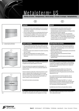
L8542054
Rev. 01/07/03
MOTORE ELETTROMECCANICO PER PORTE BASCULANTI
ELECTROMECHANICAL MOTOR FOR OVERHEAD DOORS
ELEKTROMECHANISCHER MOTOR FÜR SCHWINGTORE
MOTEUR ÉLECTROMÉCANIQUE POUR PORTES BASCULANTES
MOTOR ELECTROMECÁNICO PARA PUERTAS BASCULANTES
SILNIK ELEKTRYCZNO MECHANICZNY DO BRAM UCHYLNYYCH
ZED
Libro istruzioni e catalogo ricambi
Operating instructions and spare parts catalogue
Betriebsanleitung und Ersatzteilliste
Livret d’instructions et catalogue des pieces de rechange
Manual de instrucciones y catálogo de recambios
Książeczka z instrukcjami i katalog części wymiennych
UNIONE NAZIONALE COSTRUTTORI
AUTOMATISMI PER CANCELLI, PORTE,
SERRANDE ED AFFINI
Dichiarazione CE di conformità per macchine
(Direttiva 89/392 CE, Allegato II, parte B)
Divieto di messa in servizio
Fabbricante: Automatismi Benincà S.r.l.
Indirizzo: Via Capitello, 45 - 36066 Sandrigo (VI) - Italia
Dichiara che: lʼautomazione per porte basculanti modello ZED.
• è costruito per essere incorporato in una macchina o per essere assemblato con altri macchinari per costituire una macchina considerata dalla Direttiva 89/392 CE, come modificata;
• non è dunque conforme in tutti i punti alle disposizioni di questa Direttiva;
• è conforme alle condizioni delle seguenti altre Direttive CE:
Direttiva bassa tensione 73/23/CEE, 93/68/CEE.
Direttiva compatibilità elettromagnetica 89/336/CEE, 93/68/CEE.
e che:
• sono state applicate le seguenti (parti/clausole di) norme armonizzate:
EN 61000-6-3, EN 61000-6-1, EN 60335-1.
e inoltre dichiara che non è consentito mettere in servizio il macchinario fino a che la macchina in cui sarà incorporato o di cui diverrà
componente sia stata identificata e ne sia stata dichiarata la conformità alle condizioni della Direttiva 89/392 CE e alla legislazione
nazionale che la traspone, vale a dire fino a che il macchinario di cui alla presente dichiarazione non formi un complesso unico con
la macchina finale.
Benincà Luigi, Responsabile legale.
Sandrigo, 01/07/2004.
Declaration by the manufacturer
(Directive 89/392/EEC, Art. 4.2 and Annex II, sub B)
Divieto di messa in servizio
Manufacturer: Automatismi Benincà S.r.l.
Address: Via Capitello, 45 - 36066 Sandrigo (VI) - Italia
Herewith declares that: the operator for overhead doors model ZED.
• is intended to be incorpored into machinery or to be assembled with other machinery to constitute machinery covered by Directive
89/392 EEC, as amended;
• does therefore not in every respect comply with the provisions of this Directive;
• does comply with the provisions of the following other EEC Directives:
Direttiva bassa tensione 73/23/CEE, 93/68/CEE.
Direttiva compatibilità elettromagnetica 89/336/CEE, 93/68/CEE.
and that:
• the following (parts/clauses of) harmonized standards have been applied:
EN 61000-6-3, EN 61000-6-1, EN 60335-1.
and furthermore declares that it is not allowed to put the machinery into service until the machinery into which it is to be incorporated
or of which it is to be a component has been found and declared to be in conformity with the provisions of Directive 89/392/EEC and
with national implementing legislation, i.e. as a whole, including the machinery referred to in this declaration.
Benincà Luigi, Responsabile legale.
Sandrigo, 01/07/2004.
2
Herstellerklärung
(gemäß EG-Richtlinie 89/392/EWG, Artikel 4.2 und Anhang II, sub B.)
Verbot der Inbetriebnahme
Hersteller: Automatismi Benincà S.r.l.
Adresse: Via Capitello, 45 - 36066 Sandrigo (VI) - Italia
erklärt hiermit, daß: Automatisierung für Schwingtore Modell ZED.
• vorgesehen ist zum Einbau in eine Maschine oder mit anderen Maschinen zu einer Maschine im Sinne der Richtlinie 89/392/EWG,
inklusive deren Änderunge, zusammengefügt werden soll;
• aus diesem Grunde nicht in allen Teilen den Bestimmungen dieser Richtlinie entspricht;
• den Bestimmungen der folgenden anderen EG-Richtlinien entspricht:
Direttiva bassa tensione 73/23/CEE, 93/68/CEE.
Direttiva compatibilità elettromagnetica 89/336/CEE, 93/68/CEE.
und daß:
• folgende harmonisierte Normen (oder Teile/Klauseln hieraus) zur Anwendung gelangten:
EN 61000-6-3, EN 61000-6-1, EN 60335-1.
und erklärt des weiteren daß die Inbetriebnahme solange untersagt ist, bis die Maschine oder Anlage, in welche diese Maschine
eingebaut wird oder von welcher sie eine Komponente dasteilt, als Ganzes (d.h. inklusive der Maschine, für welche diese Erklärung
ausgesteilt wurde) den Bestimmungen der Richtlinie 89/392/EWG sowie dem entsprechenden nationalen Reschtserlaß zur Umsetzung
der Richtlinie in nationales Recht entspricht, und die entsprechende Konformitätserklärung ausgestellt ist.
Benincà Luigi, Responsabile legale.
Sandrigo, 01/07/2004.
Declaration du fabricant
(Directive 89/392/CEE, Article 4.2 et Annex II, Chapitre B)
Interdiction de mise en service
Fabricant: Automatismi Benincà S.r.l.
Adresse: Via Capitello, 45 - 36066 Sandrigo (VI) - Italia
Déclaire ci-apres que: lʼautomatisme pour portes basculantes modèle ZED.
• est prévue pour être incorporée dans une machine ou être assemblée avec dʼautres machines pour consituer une machine couverte
par la directive 89/392/CEE, modifiée;
• nʼest donc pas conforme en tout point aux dispositions de cette directive;
• est conforme aux dispositions des directives CEE suivantes:
Direttiva bassa tensione 73/23/CEE, 93/68/CEE.
Direttiva compatibilità elettromagnetica 89/336/CEE, 93/68/CEE.
et que:
• les (parties/paragraphes) suivants des normes harmonisées ont été appliquées:
EN 61000-6-3, EN 61000-6-1, EN 60335-1.
et déclare par ailleurs quʼil est interdit de mettre la machine en service avant que la machine dans laquelle elle sera incorporée ou
dont elle constitue une parte ait été considerée et declarée conforme aux dispositions de la Directive 89/392/CEE et aux législations
nationales la transposant, cʼest-à-dire formant un ensemble incluant la machine concernée par la présente déclaration.
Benincà Luigi, Responsabile legale.
Sandrigo, 01/07/2004.
3
Declaración CE de conformidad para maquinas
(Directiva 89/392 CE, Apartado II, parte B)
Prohibición de puesta en servicio
Fabricante: Automatismi Benincà S.r.l.
Dirección: Via Capitello, 45 - 36066 Sandrigo (VI) - Italy
Declara que: la automatización para puertas basculantes modelo ZED.
•
está construída para ser incorporada en una máquina o para ser ensamblada con otras maquinarias para construir una máquina
considerada por la Directiva 89/392 CE, como modificada;
• no es, por consiguiente, conforme en todos los puntos a la posiciones de esta Directiva;
• es conforme a las condiciones de las siguientes otras Directivas CE:
Directiva de la baja tensión 73/23/CEE, 93/68/CEE.
Directiva de compatibilidad electromagnética 89/336/CEE, 93/68/CEE
y que
• han sido aplicadas las siguientes (partes/claúsulas de) normas armonizadas:
EN 61000-6-3, EN 61000-6-1, EN 60335-1.
además declara que no ha permitido poner en servicio la maquinaria hasta que la máquina en la cual será incorporada o de la cual
resultará componente esté identificada y no sea declarada la conformidad a las condiciones de la Directiva 89/392 CE y a la legislación
nacional que le corresponda, vale decir, hasta que la maquinaria correspondiente a la presente declaración no forme un conjunto único
con la máquina final.
Benincà Luigi, Responsable legal.
Sandrigo, 01/07/2004.
Deklaracja UE o zgodności z normami dla maszyn
(Wytyczna 89/392 UE, Załącznik II, Część B)
Zakaz użytkowania
Producent: Automatismi Benincà S.r.l.
Adres: Via Capitello, 45 - 36066 Sandrigo (VI) - Italia
Oświadcza że: Automatyzm do bram uchylnych model ZED.
• został opracowany z myślą o wbudowaniu go do maszyny lub zmontowania z innymi urządzeniami w celu skonstruowania maszyny
uznanej przez Wytyczną 89/392 UE, za zmodyfikowaną;
• nie jest więc zgodny we wszystkich punktach z Wytyczną;
• jest natomiast zgodny z wymogami innych, poniżej wyszczególnionych, Wytycznych UE:
Wytyczna o niskim napięciu 73/23/EWG i 93/68/EWG
Wytyczna o zdolności współdziałania elektromagnetycznego 89/336/EWG, 93/68/EWG.
i że:
• zastosowane zostały następujące normy (ich klauzule/części) standard:
EN 61000-6-3, EN 61000-6-1, EN 60335-1.
ponadto oświadcza, że zabronione jest stosowanie automatyzmu do czasu kiedy maszyna, do której ma być wbudowany lub stanowić
jej element składowy, nie uzyska świadectwa identyfikacyjnego oraz świadectwa orzekającego jej zgodność z wymogami Wytycznej
89/392 UE oraz z przepisami obowiązującymi w kraju sprowadzającym urządzenie, a więc do czasu kiedy automatyzm stanowiący
przedmiot niniejszego oświadczenia nie stanie się częścią składową urządzenia gotowego.
Benincà Luigi, Radca prawny
Sandrigo, 01/07/2004.
4
Dati tecnici
Technical data
Technische Daten
Donnees technique
Datos técnicos
Dane techniczne
ZED
Alimentazione
Power supply
Speisung
Alimentation
Alimentación
Napięcie zasilania
Assorbimento.
Consumption
Stromaufnahme
Absorption
Consumo
Pobór prądu
Potenza nominale
Power
Leistung
Puissance
Potencia
Pobór mocy
Coppia nominale
Torque
Drehmoment
Couple
Par
Moment obrotowy
Intermittenza lavoro
Jogging
Betriebsschaltung
Intermittence travail
Intermitencia operación
Przerywacz pracy
30%
Tempo apertura
Operating time
Betätigungszeit
Temps manoeuvre
Tiempo maniobra
Czas posuwu skrzydła
≈10s
Grado di protezione
IP class
IP Grad
Degré IP
Índice IP
Stopień IP
IP40*
Interv. termoprotez.
Thermal switch trig.
Temperaturschutzschalter Interv. protect. therm.
Interv. termoprotección
Działanie termowył.
130°C
Betriebstemperatur
Temp. fonctionnement
Temp. funcionamiento
Temperatura działania
Condensatore
Capacitor
Kondensator
Condensateur
Condensador
Kondensator
Rumorosità
Noise level
Geräuschentwicklung
Bruit
Ruido
Max. halas
Lubrificazione
Lubrication
Schmierung
Lubrification
Lubrificación
Smarowanie
Peso
Weight
Gewicht
Poids
Peso
Ciężar
Temp. funzionamento Operat. temperature
230Vac (50Hz)
0,85A
170W
480Nm
-20°C/+40°C
9µF
<70dB
AGIP GRLP1
10 kg
Disponibile versione IP44 - Available version IP44 - Vorhandene Version IP44 - Disponible version IP44 - Disponible versión IP44
100
Dimensioni d’ingombro
Overall dimensions
Abmessungen
Dimensions d’encombrement
Dimensiones exteriores
Wymiary gabarytowe
30
390
1250 (AU.125)
1950 (AU.20)
630
630
240
65
176
137
5
A
Braccio del basculante
Arm of the tilting mechanism
Arm des Schwingtors
Bras de la porte basculante
Brazo de la puerta basculante
Ramię bramy uchylnej
10
0
R
Fig.1
Curare l’allineamento dei due motori.
Take care to align the two motors.
Die beiden Motoren sorgfältig miteinander fluchten.
Veiller à l’alignement des deux moteurs.
Prestar atención a la alineación de los dos motores.
Ustawianie na osi dwóch siłowników.
L
n
Mi
m
0m
22
100
L/2
100
R
R
Installazione motore singolo centrale
Installation of a single central motor
Installation eines einzelnen, zentralen Motors
Installation moteur unique central
Instalación de un motor central
Instalacja jednopunktowa z jednym siłownikiem w centralnym
miejscu bramy
Fig.2
6
Installazione laterale di 2 motori per basculante con portina.
Side installations of 2 motors for an overhead door with small door.
Seitliche Installation von 2 Motoren für ein Schwingtor mit Fußgängertür.
Installation latérale de 2 moteurs pour porte basculante avec porte
piéton incorporée.
Instalación lateral de 2 motores para basculante con puerta.
Instalacja dwupunktowa z 2 siłownikami umieszczonymi po jednym na
obu bokach bramy uchylnej posiadającej drzwi wejściowe.
Fig.3
P
Fissare con n° 4 viti autofilettanti Ø4.8 o con viti M5 o con rivetti Ø4.8.
Secure with 4 self-tapping screws Ø4.8 or with M5 screws or with rivets Ø4.8.
Mit 4 selbstschneidenden Schrauben Ø4.8, mit Schrauben M5 oder Nieten
Ø4.8 befestigen.
Fixer avec n° 4 vis autotaraudeuses Ø 4,8 ou avec vis M5 ou avec rivets Ø
4,8.
Fijar con 4 tornillos de autorrosca Ø4.8 o con tornillos M5 o con remaches Ø4.8.
Mocować za pomocą 4 śrub samogwintujących o Ø 4.8, śrub M5 lub naciętych gwoździ
dwułebkowych o Ø 4.8.
Saldare su tutto il contorno
Weld all round the border
Entlang der gesamten Außenlinie schweißen
Souder sur tout le pourtour
Soldar en todo el contorno
Spawać na całym konturze
Braccio diritto
Straight arm
Gerader Arm
Bras droit
Brazo recto
Ramię proste
Braccio curvo
Curved arm
Gebogener Arm
Bras courbe
Brazo curvo
Ramię zakrzywione
B
Fig.4
100
100
Mettere a livello
Set level
Gerade ausrichten
Mettre de niveau
Nivelar
Wypoziomowanie
S
Regolare per ottenere il parallelismo del tubo con la porta basculante
Regulate to obtain parallel positioning of the tube with respect to the overhead
door
So regulieren, dass ein perfekter Parallelismus des Rohrs mit dem Schwingtor
erhalten wird.
Régler pour obtenir le parallélisme du tube avec la porte basculante
Regular para que el tubo esté paralelo a la puerta basculante
Regulować do momentu równoległego ustawienia rurki z bramą uchyln
Fig.5
T
R
Fig.6
7
Tagliare
Cut
Schneiden
Couper
Cortar
Odciąć
P
10
Piatto del braccio diritto
Flat part of the straight arm
Teller des geraden Arms
Plat du bras droit
Plato del brazo recto
Listwa prowadnicza ramienia prostego
T
Saldare su tutto il contorno
Weld all round the border
Entlang der gesamten Außenlinie schweißen
Souder sur tout le pourtour
Soldar en todo el contorno
Spawać na całym konturze
Fig.7
P
Tubo del braccio diritto
Tube of the straight arm
Rohr des geraden Arms
Tube du bras droit
Tubo del brazo recto
Rurka ramienia prostego
10
Tagliare
Cut
Schneiden
Couper
Cortar
Odciąć
Fig.8
8
2H
1/
0
10
2H
1/
Fig.9
Per evitare che sporga, il motore può essere montato con la lampada di
cortesia verso il basso.
To prevent it protruding, the motor must be fitted with the courtesy light
pointing downwards.
Damit der Motor nicht übersteht, kann er so montiert werden, dass die
Notbeleuchtung nach unten zeigt.
Pour éviter qu’il dépasse, le moteur peut être monté avec l’éclairage
automatique vers le bas
Para que el motor no sobresalga, se puede montar con la lámpara de cortesía
hacia abajo.
By zapobiec wychylaniu się siłownika, można go montować z lampą tylną
skierowaną do dołu.
2/3 H
H
1/3 H
120
Max 1200
La quota 100 sulle porte basculanti normali diventa 120
dallo snodo del telo basculante all’asse motore.
The height 100 on normal overhead doors becomes 120
from the articulation of the tilting sheet to the motor axis.
Die Quote 100 an normalen Schwingtoren wird zu 120 ab
dem Gelenkteil des Schwingtorblatts bis zur Motorachse.
La hauteur 100 sur les portes basculantes normales
devient 120 de l’articulation du tablier basculant à
l’axe moteur.
La cota 100 en las puertas basculantes normales será de
120 desde la articulación del panel basculante hasta el
eje del motor.
Poziom odpowiadający liczbie 100 w przypadku bram
uchylnych zwyczajnych dochodzi do 120, odległość od
przegubu pancerza uchylnego do wału silnika.
Fig.10
9
Funzionamento Automatico
Automatic operation
Automatikbetrieb
Fonctionnement automatique
Funcionamiento automático
Funkcjonowanie automatyczne
Fig.11
Sblocco per manovra manuale
Release for manual manoeuvring
Entriegelung zur manuellen Bedienung
Déblocage pour manœuvre manuelle
Desbloqueo para maniobra manual
Rozsprzęglanie dla manewru ręcznego
K
C
G
L
K
G
S
Registro
Register
Register
Vis de réglage
Tornillo de regulación
Rejestr
Registro
Register
Register
Vis de réglage
Tornillo de regulación
Rejestr
Morsetto
Clamp
Klammer
Serre-câble
Terminal
Zacisk
Maniglia con piastra
Handle with plate
Handgriff mit platte
Poignée avec plaque
Manilla con placa
Uchwyt z płytą
Rosetta 9x24 UNI 6593
Washer 9x24 UNI 6593
Scheibe 9x24 UNI 6593
Rondelle 9x24 UNI 6593
Arandela 9x24 UNI 6593
Podkładka 9x24 UNI 6593
Rosetta per M8 DIN 6798E
Washer M8 DIN 6798E
Scheibe M8 DIN 6798E
Rondelle M8 DIN 6798E
Arandela para M8 DIN 6798E
Podkładka dla M8 DIN 6798E
Vite M8x10 UNI 5739
Screw M8x10 UNI 5739
Schraube M8x10 UNI 5739
Vis M8x10 UNI 5739
Tornillo M8x10 UNI 5739
Sruba M8x10 UNI 5739
Fig.12
10
S
Maniglia con piastra
Handle with plate
Handgriff mit platte
Poignée avec plaque
Manilla con placa
Uchwyt z płytą
Morsetto
Clamp
Klammer
Serre-câble
Terminal
Zacisk
S
G
52
Ø
P
8
ø 16mm
27
Fig.13
S
R
ø 7mm
Fig.14
P
A
45°
Fig.15
11
A
G
Posticipa.
Delay.
Verlangsamt.
Retarde.
Retrasa.
Opóźnia.
Anticipa.
Anticipate.
Beschleunigt.
Anticipe.
Anticipa.
Przyspiesza.
Fig.16
ZED
Pos.
12
Denominazione - Description - Bezeichnung - Dénomination - Denominación - Określenie
Cod.
1
Contenitore
centrale
Control unit
container
Gehäuse für
Steuerzentrale
Coffret logique de
commande
Caja de la central
Obudowa centralki
9686103
2
Centrale
Control unit
Steuerzentrale
Logique de commande
Central
Centralka
9686104
3
Trasformatore
Transformer
Transformator
Transformateur
Transformador
Transformator
9686124
4
Lampadina
Light
Lampe
Lampe
Lámpara
Lampka
9686125
5
Pulsante Nero
Black button
Schwarze Taste
Bouton-poussoir noir
Pulsador negro
Przycisk Czarny
9686151
6
Pulsante Rosso
Red button
Rote Taste
Bouton-poussoir rouge
Pulsador rojo
Przycisk Czerwony
9686152
7
Guarnizione
Gasket
Dichtung
Joint
Junta
Uszczelka
9686153
8
Condensatore
Condenser
Kondensator
Condensateur
Condensador
Kondensator
9686154
9
Pignone
Pinion
Ritzel
Pignon
Piñón
Koło zębate
9686011
10
Albero uscita
Output shaft
Abtriebswelle
Arbre sortie
Eje de salida
Wał wyjściowy
9686009
11
Pignone
Pinion
Ritzel
Pignon
Piñón
Wał napędowy
9686170
12
Albero motore
Motor shaft
Motorwelle
Arbre moteur
Eje del motor
Wał silnika
9686168
13
Calotta Motore
Motor cap
Motorkalotte
Calotte Moteur
Cuerpo del motor
Pokrywa Silnika
9686155
14
14
Carter SX
Carter DX
Casing SX
Casing DX
Gehäuse SX
Gehäuse DX
Carter SX
Carter DX
Cárter SX
Cárter DX
Karter SX
Karter DX
9686156
9686368
15
Maniglia sblocco
Release handle
Entriegelungshebel
Poignée déblocage
Manilla de desbloqueo
Klamka pokrętna odblok.
9686157
16
Camme FC
Limit stop cams
Endschalternocken
Cames FC
Álabes FC
Krańcówki Krzywki
9686158
17
17a
Finecorsa
Finecorsa IP44
Limit stop
IP44 Limit stop
Endschalter
Endschalter IP44
Fins de course
Fins de course IP44
Fines de carrera
Fines de carrera IP44
Krańcówka
Krańcówka IP44
9686292
9686260
4
2
5
1
6
3
8
9
10
7
17
14
11
16
12
13
15
13
Introduzione
Ci congratuliamo con Voi per aver scelto il motoriduttore ZED.
Tutti gli articoli della vasta gamma Benincà sono il frutto di una ventennale esperienza nel settore degli automatismi e
di una continua ricerca di nuovi materiali e di tecnologie all’avanguardia.
Proprio per questo, oggi siamo in grado di offrire dei prodotti estremamente affidabili che, grazie alla loro potenza,
efficacia e durata, soddisfano pienamente le esigenze dell’utente finale.
Tutti i nostri prodotti vengono costruiti in conformità alle normative vigenti e sono coperti da garanzia.
Inoltre, una polizza R. C. prodotti stipulata con primaria compagnia assicurativa copre eventuali danni a cose o persone
causati da difetti di fabbricazione.
1. Notizie generali
Per un buon funzionamento dell’automazione in oggetto, la porta basculante deve rispondere alle seguenti caratteristiche:
- buona robustezza e rigidità
- buona equilibratura
- buona scorrevolezza delle guide.
In ogni caso l’apertura e la chiusura manuali devono potersi eseguire con facilità.
2. Caratteristiche generali
ZED è un’automazione per porte basculanti a contrappesi, a montaggio centrale o laterale.
Compatto e lineare, il motoriduttore ZED si adatta a qualsiasi tipo di porta basculante.
ZED oltre a garantire il massimo dell’affidabilità, offre un movimento continuo, regolare e silenzioso. L’applicazione è
di facile esecuzione e può avvenire mediante viti o saldatura.
L’irreversibilità del motoriduttore assicura la chiusura della porta senza l’impiego di elettroserrature.
In caso di mancanza di corrente lo sblocco avviene mediante la semplice rotazione di una manopola situata sul
motoriduttore..
3. Accessori indispensabili per il montaggio
-
Braccio dritto AU.D oppure braccio curvo AU.C.
Coppia di tubi L 1500 mm con bussola e staffe AU.45Z (solo per montaggio centrale).
Bussola calettata AU.45B (solo per montaggio laterale).
4. Accessori supplementari
-
-
Tubo L 150 mm con bussola e staffa (per montaggio laterale) AU.45T.
Braccio dritto con bussola saldata AU.D45 (evita la saldatura in opera della bussola AU.45B al braccio AU.D).
AU.45L bussola di collegamento tra il motoriduttore ed il tubo di torsione senza saldatura (spinata) completo con
tubo di torsione L 2000 mm.
N.B.: Questo accessorio unito al AU.D45 ed al AU.G45 permette l’installazione completa senza effettuare alcuna
saldatura.
Innesto con staffa AU.G45 (permette il collegamento del braccio AU.D45 al tubo AU.45Z senza saldature).
Sblocco da esterno con chiave personalizzata ZED.E.
Sblocco dainterno/esterno a maniglia con chiave personalizzata ZED.SE.
ZED.MS sblocco a filo.
5. Messa in posa dell’automatismo
5.1 Prefazione
L’automazione con un solo motore a montaggio centrale è consigliabile per porte basculanti di area inferiore od uguale
a 12 m2; per dimensioni superiori o per basculanti con portina utilizzare n° 2 motori laterali.
5.2 Operazione n° 1
Individuato l’asse di rotazione della porta basculante A, determinare l’asse R passante inferiormente alla distanza di
100 mm (fig. 1); questo è l’asse dell’albero scanalato uscente dal motoriduttore.
Ancorare quindi la piastra del motoriduttore alla porta seguendo le indicazioni delle figg. 2 e 3.
5.3 Operazione n° 2 (fig. 4).
Fissare la piastrina P sul montante o sul traverso superiore della basculante oppure a muro a fianco del braccio della
porta. (In ogni caso il braccio B deve essere sistemato tra il montante ed il braccio della porta basculante; se questo
spazio è insufficiente utilizzare il braccio curvo art. AU.C che permette di lavorare in asse con il braccio della porta
basculante).
5.4 Operazione n° 3 (fig. 6).
Fissare provvisoriamente la staffa S con il tubo T infilato sia in quest’ultima che nell’albero scanalato del
motoriduttore.
14
Rilevare la misura del tubo T in modo che sia allineato al braccio B.
Tagliare quindi il tubo a misura.
Fissare ora la staffa S mediante viti o rivetti avendo cura di mettere in bolla il tubo T.
Quest’ultimo deve anche essere parallelo al telo della basculante; a tal proposito usufruire della regolazione di cui fig.
5.
5.5 Operazione n° 4
Portare la porta basculante in apertura e tagliare i due componenti del braccio dritto secondo le indicazioni delle figg.
7 e 8.
Saldare poi il piatto del braccio al tubo T (fig. 7) oppure utilizzare il braccio AU.D45.
Infilare il piatto nel tubo e quindi fissare quest’ultimo al piatto P mediante vite M10 e dado autobloccante (in dotazione).
5.6 Operazione n° 5
Se necessario riequilibrare la porta aumentando i contrappesi o il tiro delle molle in modo che le manovre manuali
risultino facili da compiere.
6. Applicazioni particolari
Oltre alle normali porte basculanti (a contrappeso e guide verticali), ZED consente di automatizzare:
6.1 Porte a guide orizzontali e verticali fig. 9 (l’installazione risulta analoga a quella descritta al punto 5).
6.2 Porte basculanti snodate (fig. 10). Per l’installazione seguire il punto 5 integrato con le indicazioni di fig.10.
6.3 Porte basculanti a molla (per il montaggio seguire le indicazioni del punto 5).
N.B.: Per poter essere automatizzate queste porte devono però essere a guida verticale.
7. Manovra manuale
La manovra manuale della porta basculante è realizzabile in diversi modi:
7.1 Sblocco interno a maniglia (fig. 11).
• Ruotare di 90° la manopola di sblocco come indicato in Fig.11
• L'automazione è così disinserita. E' ora possibile aprire/chiudere manualmente l'anta.
• Per ripristinare il funzionamento automatico, riportare la la manopola di sblocco nella posizione iniziale.
7.2 Sblocco a filo art. ZED.MS (fig. 12-13).
Nota: Lo sblocco a filo può essere installato con la guaina a sinistra o a destra dell'attuatore, a seconda della
posizione della maniglia di apertura della porta. In fig.12 sono illustrate entrambe le installazioni.
E' necessario praticare un piccolo foro per il passagio della guaina, le quote di foratura, valide per entrambi i lati
del carter sono indicate in fig.13.
• Infilare il cavo di acciaio C sulla leva L.
• Passare la guaina G con il capocorda K fino a mandarla in battuta sul corpo carter del motore.
(Nel caso di guaina a destra il cavo viene inserito dalla parte opposta e il capocorda K va in battuta sulla leva L)
• Fissare il cavo di acciaio C nella maniglia con il morsetto come indicato in fig. 12.
• Fissare la staffa S.
• Mettere in tensione il cavo utilizzando la vite di registro.
• Ruotare la maniglia per sbloccare.
• Ruotando nuovamente la maniglia, la prima manovra ripristinerà il normale funzionamento.
7.3 Sblocco esterno con chiave personalizzata ZED.E (fig. 14).
• Fissare il perno P, al perno di sblocco S utilizzando l’apposito grano G, come indicato in figura 14.
• In asse con il perno di sblocco S realizzare un foro di circa 16mm di diametro.
• Utilizzando la piastrina R come dima di foratura realizzare i due fori laterali ø 7 mm per le viti di fissaggio.
• Fissare la piastrina alla porta.
7.4 Sblocco interno/esterno a maniglia con chiave personalizzata ZED.SE (Fig.15)
• Fissare la piastrina P prima di montare l'attuatore, in posizione 45° come indicato in Fig.15.
• Provedere al montaggio dello sblocco tagliando l'astina A a misura.
8. Regolazione dei finecorsa (fig. 16)
ZED dispone di finecorsa incorporati sia per l’apertura che per la chiusura, per la regolazione agire come segue:
•
Svitare la vite V e togliere il carter C.
•
Allentare il grano G.
•
Ritardare o anticipare l’intervento del finecorsa ruotando la camma A e serrare moderatamente il grano G.
ATTENZIONE
La polizza RC prodotti, che risponde di eventuali danni a cose o persone causati da difetti di fabbricazione, richiede la
conformità dell’impianto alle normative vigenti e l’utilizzo di accessori originali Benincà.
15
Introduction
We congratulate you for choosing the ZED gear motor.
All the items in the vast Benincà range are the fruit of twenty years of experience in the sector of automatisms and of
a continuous search for new materials and state-of-the-art technologies.
For this very reason, today we are able to offer extremely reliable products which, thanks to their power, efficiency and
long life, fully satisfy the demands of the end user.
All our products are made in conformity with the regulations in force and are covered by guarantee.
Moreover, a TPL policy stipulated with a leading insurance company covers any damage to persons or things caused
by manufacturing defects.
1. General information
For good operation of this automation, the overhead door must possess the following characteristics:
- good robustness and rigidity
- good balancing
- good sliding of the guides.
In any case, it must be possible to perform manual opening and closing with ease.
2. General characteristics
ZED is an automation for overhead doors with counterweights, for central or side assembly.
Compact and linear, the ZED gear motor adapts to any type of overhead door.
As well as guaranteeing maximum reliability, ZED offers a continuous, regular and silent movement.
It is easy to fit using screws or welding.
The gear motor is irreversible which ensures that the door can be closed without the use of electric locks.
In the event of a power cut the door may be released by simply turning a knob on the gear motor.
3. Indispensable accessories for assembly
-
Straight arm AU.D or curved arm AU.C.
Pair of tubes L 1500 mm with bush and brackets AU.45Z (only for central assembly).
Keyed-on bush AU.45B (only for side assembly).
4. Additional accessories
-
-
Tube L 150 mm with bush and bracket (for side assembly) AU.45T.
Straight arm with welded bush AU.D45 (avoids on-site welding of the bush AU.45B to the arm AU.D).
AU.45L connecting bush between the gear motor and the torque tube without welding (with a dowel) complete
with torque tube L 2000 mm.
N.B.: Together with the AU.D45 and the AU.G45, this accessory allows complete installation without making any
welds.
Coupling with bracket AU.G45 (allows the connection of the arm AU.D45 to the tube AU.45Z without welds).
External release with customized key ZED.E.
Release from inside/outside by means of a handle with customized key ZED.SE.
ZED.MS wire release.
5. Installing the automatism
5.1 Preface
The automation with only one motor and central assembly is recommended for overhead doors with an area less than
or equal to 12 m2; for larger dimensions or for overhead doors with a built-in small door use 2 side motors.
5.2 Operation n° 1
After identifying the axis of rotation of the overhead door A, determine the axis R passing through the bottom at a distance of 100 mm (fig. 1); this is the axis of the splined shaft that comes out of the gear motor.
Then anchor the plate of the gear motor to the door following the indications in figs. 2 and 3.
5.3 Operation n° 2 (fig. 4).
Fix the plate P onto the upright or the upper cross member of the overhead door or onto the wall next to the arm of the
door. (In any case the arm B must be positioned between the upright and the arm of the overhead door; if this space is
insufficient, use the curved arm art. AU.C which allows you to work in axis with the arm of the overhead door.
5.4 Operation n° 3 (fig. 6).
Provisionally fix the bracket S with the tube T, inserted both into the bracket and into the splined shaft of the gear motor.
Measure the tube T so that it is aligned with the arm B.
Then cut the tube to size.
Now fix the bracket S with screws or rivets, taking care to set the tube T absolutely level.
16
The tube must also be parallel to the sheet of the overhead door; to ensure this, regulate as shown in fig. 5.
5.5 Operation n° 4
Bring the overhead door into open position and cut the two components of the straight arm following the indications
in figs. 7 and 8.
Then weld the flat part of the arm to the tube T (fig. 7) or use the arm AU.D45.
Insert the flat part in the tube and then fix the latter to the flat part P with a screw M10 and self-locking nut (provided).
5.6 Operation n° 5
If necessary rebalance the door by increasing the counterweights or the pull of the springs so that manual manoeuvres
can be performed easily.
6. Particular applications
As well as ordinary overhead doors (with counterweight and vertical guides), ZED can be used for the automated operation of:
6.1 Doors with horizontal and vertical guides, fig. 9 (the installation is similar to that described in point 5).
6.2 Articulated overhead doors (fig. 10). For installation follow point 5 integrated with the indications in fig.10.
6.3 Overhead doors with a spring (for installation follow the indications in point 5).
N.B.: In order to be automated these doors must have a vertical guide.
7. Manual manoeuvre
The manual manoeuvre of the overhead door may be achieved in various ways:
7.1 Internal release of the handle (fig. 11).
•
Turn the release knob by 90° as indicated in Fig.11
•
In this way the automation is deactivated. It is now possible to open/close the door by hand.
•
To restore automatic operation, return the release knob to its initial position.
7.2 Wire release art. ZED.MS (fig. 12-13).
Note: The wire release may be installed with the sheath on the left or the right of the actuator, depending on the
position of the handle for opening the door. Fig. 12 shows both installations.
It is necessary to make a small hole for the sheath to pass through; the drilling measurements, valid for both sides
of the casing, are indicated in fig.13.
•
Fit the steel cable C onto the lever L.
•
Pass the sheath G with the cable terminal K until it rests against the motor casing body.
(If the sheath is on the right the cable is inserted from the opposite side and the cable terminal K rests against the
lever L)
•
Fix the steel cable C in the handle with the terminal as indicated in fig. 12.
•
Fix the bracket S.
•
Tighten the cable using the registering screw.
•
Turn the handle to release it.
•
When the handle is turned again, the first manoeuvre will restore normal operation.
7.3 External release with customised key ZED.E (fig. 14).
•
Fix the pin P to the release pin S using the special dowel G, as indicated in figure 14.
•
On axis with the release pin S, make a hole with a diameter of about 16mm.
•
Using the plate R as a drilling template, make the two holes at the sides ø 7 mm for the fixing screws.
•
Fix the plate to the door.
7.4 Release from inside/outside by means of a handle with customized key ZED.SE (Fig.15)
• Fix the plate P before fitting the actuator, in position 45° as indicated in Fig.15.
• Assemble the release mechanism, cutting the rod A to size.
8. Regulation of the limit stops (fig. 16)
ZED has built-in limit stops both for opening and for closing; to regulate them, proceed as follows:
•
Unscrew the screw V and remove the casing C.
•
Slacken the dowel G.
•
Delay or anticipate the intervention of the limit stop by rotating the cam A and moderately tighten the dowel G.
ATTENTION
The TPL policy on the products, which covers any damage to persons or things caused by manufacturing defects,
requires that the system comply with the regulations in force and that authentic Benincà accessories be used.
17
Einführung
Wir beglückwünschen Sie zum Kauf des Getriebemotors ZED.
Alle Artikel des reichen Benincà-Angebots sind das Ergebnis einer zwanzigjährigen Erfahrung auf dem Gebiet der Automatisierung und der ständigen Erforschung neuer Materialien und moderner Technologien.
Eben darum sind wir heute in der Lage, extrem zuverlässige Produkte anzubieten, die dank ihrer Leistungsfähigkeit, Effizienz
und Haltbarkeit alle Anforderungen des Endverbrauchers voll erfüllen.
Alle unsere Produkte werden in Konformität mit den einschlägigen Normen konstruiert und sind mit einer Garantie ausgestattet.
Daneben gewährleistet eine Produkthaftpflichtversicherung bei einer führenden Versicherungsagentur die Deckung eventueller
Sach- oder Personenschäden, die durch Fabrikationsfehler entstehen können.
1. Allgemeine Hinweise
Für die einwandfreie Funktion der Automatisierung muss das Schwingtor folgende Merkmale aufweisen:
- gute Robustheit und Steifigkeit
- gute Auswuchtung
- gutes Gleitvermögen der Führungen.
Die manuelle Bedienung für Öffnen und Schließen muss in jedem Fall problemlos sein.
2. Allgemeine Merkmale
ZED ist eine Automatisierung für Schwingtore mit Gegengewicht mit seitlicher oder zentraler Montage.
Der kompakte, lineare Getriebemotor ZED eignet sich für jeden Schwingtortyp.
ZED garantiert nicht nur für maximale Zuverlässigkeit, sondern bietet eine kontinuierliche, flüssige und geräuschlose Bewegung. ZED ist einfach anzubringen und kann angeschraubt oder angeschweißt werden.
Die Nichtumkehrbarkeit des Getriebemotors sorgt für den zuverlässigen Verschluss des Tors, ohne Einsatz von Elektroschlössern.
Im Falle eines Stromausfalls erfolgt die Entriegelung einfach durch Verstellen des Drehknopfs am Getriebemotor.
3. Zur Montage notwendiges Zubehör
-
Gerader Arm AU.D, oder gebogener Arm AU.C.
Paar Rohre L 1500 mm mit Buchse und Bügel AU.45Z (nur für zentrale Montage).
Aufgezogene Buchse AU.45B (nur für seitliche Montage).
4. Optionales Zubehör
-
-
Rohr L 150 mm mit Buchse und Bügel (für seitliche Montage) AU.45T.
Gerader Arm mit geschweißter Buchse AU.D45 (dadurch wird das Anschweißen der Buchse AU.45B an den Arm AU.D
vor Ort vermieden).
AU.45L Verbindungsbuchse zwischen Getriebemotor und Torsionsstab, ohne Schweißen (verdübelt), komplett mit
Torsionsstab L 2000 mm.
NB: Dieses Zubehör ermöglicht in Verbindung mit AU.D45 und AU.G45 die vollständige Installation, ganz ohne Schweißungen.
Kupplungsstück mit Bügel AU.G45 (ermöglicht die Verbindung des Arms AU.D45 mit dem Rohr AU.45Z, ohne Schweißungen).
Entriegelung von außen mittels personalisiertes Schlüssels ZED.E.
Griff-Entriegelung von innen/außen mit personalisiertem Schlüssel ZED.SE.
ZED.MS Kabel-Entriegelung
5. Installation der Torautomatisierung
5.1 Vorwort
Die Torautomatisierung mit nur einem, mittig montierten Motor empfiehlt sich für Schwingtore mit einer Fläche bis 12 m2; während für größere Tore oder für Schwingtore mit Durchgangstür vorzugsweise zwei seitliche Motoren zu verwenden sind.
5.2 Operation 1
Die Drehachse des Schwingtors A ausmachen und die Achse R bestimmen, die mit einem Abstand von 100 mm (Abb. 1) unter
A verläuft; dies ist die Keilwelle, die aus dem Getriebemotor austritt.
Nun die Platte des Getriebemotors gemäß der Anweisungen der Abb. 2 und 3 am Tor verankern.
5.3 Operation 2 (Abb. 4).
Das Plättchen P am Ständer oder am oberen Querträger des Schwingtors, oder aber an der Wand, seitlich des Torarms
befestigen. (Der Arm B muss in jedem Fall zwischen Ständer und Arm des Schwingtors angebracht werden; wenn nicht genügend Platz zur Verfügung steht, einfach den gebogenen Arm Art. AU.C verwenden, der das axial zum Arm des Schwingtors
ausgerichtete Arbeiten ermöglicht).
5.4 Operation 3 (Abb. 6).
Den Bügel S provisorisch befestigen, wobei das Rohr T sowohl an diesem, als auch an der Keilwelle des Getriebemotors
18
eingesteckt sein muss.
Das Maß des Rohrs T aufnehmen, so dass es mit dem Arm B gefluchtet wird.
Jetzt das Rohr zuschneiden.
Nun den Bügel S mit Schrauben oder Nieten befestigen, wobei das Rohr T gerade auszurichten ist.
Das Rohr muss auch parallel zum Schwingtorblatt stehen; zu diesem Zweck die Einstellung der Abb. 5 nutzen.
5.5 Operation 4
Das Schwingtor öffnen und die beiden Teile des geraden Arms gemäß der Anweisungen der Abb. 7 und 8 zuschneiden.
Dann den Teller des Arms am Rohr T anschweißen (Abb. 7), oder den Arm AU.D45 verwenden.
Den Teller in das Rohr einführen und letzteres mittels Schraube M10 und selbstsperrender Mutter (mitgeliefert) am Teller P
befestigen.
5.6 Operation 5
Falls erforderlich das Tor erneut auswuchten, indem die Gegengewichte vermehrt oder der Zug der Federn verstärkt wird, so
dass die manuelle Bedienung einfach auszuführen ist.
6. Sonderanwendungen
Neben normalen Schwingtoren (mit Gegengewichten und vertikalen Führungen) ermöglicht ZED die Automatisierung der
folgenden Tore:
6.1 Tore mit horizontalen und vertikalen Führungen Abb. 9 (die Installation ist wie die unter Punkt 5 beschriebene).
6.2 Gelenk-Schwingtore (Abb. 10). Für die Installation den Punkt 5 und die Anweisungen der Abb.10 befolgen.
6.3 Schwingtore mit Feder (für die Installation die Anweisungen des Punkts 5 befolgen).
NB: Derlei Tore müssen jedoch vertikale Führungen haben, damit sie automatisiert werden können.
7. Manuelle Bedienung
Die manuelle Bedienung der Schwingtore ist auf verschiedene Arten möglich:
7.1 Entriegelung von Innen mit Griff (Abb. 11).
•
Den Entriegelungsknauf um 90° drehen, wie in der Abb.11 gezeigt.
•
Damit ist die Automatisierung ausgeschlossen und das Tor kann von Hand geöffnet und geschlossen werden.
•
Um den Automatikbetrieb wieder herzustellen, den Entriegelungsknauf auf die Ausgangsposition zurückstellen.
7.2 Kabel-Entriegelung Art. ZED.MS (Abb. 12-13).
Hinweis: Die Kabel-Entriegelung kann mit Hülle links oder rechts vom Trieb installiert werden, je nach Position des
Torgriffs. In der Abb.12 sind beide Installationsmöglichkeiten aufgezeigt.
Dazu muss ein kleines Bohrloch für den Durchgang der Hülle ausgeführt werden. Die Bohrquoten, die für beide Seiten
des Gehäuses gelten, sind in der Abb.13 angegeben.
•
Das Stahlkabel C am Hebel L einführen.
•
Die Hülle G mit dem Kabelschuh K bis zum Anschlag am Körper des Motorgehäuses durchführen.
(Bei Hülle an der rechten Seite wird das Kabel an der entgegengesetzten Seite eingeführt und der Anschlag des Kabelschuhs K ist der Hebel L).
•
Den Bügel S befestigen.
•
Das Stahlkabel C mit der Klemme am Griff befestigen, wie in der Abb. 12 gezeigt.
•
Das Kabel mit Hilfe der Stellschraube spannen.
•
Den Griff drehen, um zu entriegeln.
•
Den Griff erneut drehen, das erste Manöver stellt den normalen Betrieb wieder her.
7.3 Äußere Entriegelung mit personalisiertem Schlüssel ZED.E (Abb. 14).
•
Den Bolzen P mit dem speziellen Stift G am Entriegelungsbolzen S befestigen, wie in der Abbildung 14 gezeigt.
•
Axial zum Entriegelungsbolzen S ein Bohrloch mit zirka 16 mm Durchmesser erstellen.
•
Unter Verwendung des Plättchens R als Bohrschablone die beiden seitlichen Löcher mit ø 7 mm für die Befestigungsschrauben erstellen.
•
Das Plättchen am Tor befestigen.
7.4 Innere/äußere Griff-Entriegelung mit personalisiertem Schlüssel ZED.SE (Abb.15)
• Das Plättchen P befestigen, bevor der Trieb in einer 45°-Position installiert wird, wie in der Abb.15 gezeigt.
• Nun die Entriegelung montieren, indem der Stab A maßgenau zugeschnitten wird.
8. Einstellen der Endschalter (Abb. 16)
ZED ist mit eingebauten Endschaltern für Öffnen und Schließen ausgestattet, die wie folgt eingestellt werden:
•
Die Schraube V aufschrauben und das Gehäuse C ausbauen.
•
Den Stift G lockern.
•
Das Auslösen des Endschalters vor- oder nachverlegen, indem der Nocken A verstellt wird, und den Stift G mäßig
festziehen.
ACHTUNG
Die Produkthaftpflichtpolice, die eventuelle Sach- oder Personenschäden deckt, die durch Fabrikationsfehler entstehen
können, setzt die Konformität der Anlage mit den einschlägigen Vorschriften und die Verwendung von Originalzubehör von
Benincà voraus.
19
Introduction
Nous vous félicitons d’avoir choisi l’opérateur ZED.
Tous les articles de la vaste gamme Benincà sont le fruit de vingt ans d’expérience dans le secteur des automatismes
et d’une recherche continue de nouveaux matériaux et de technologies à l’avant-garde.
C’est justement pourquoi nous sommes aujourd’hui en mesure d’offrir des produits extrêmement fiables qui, grâce à
leur puissance, à leur efficacité et à leur durée, satisfont pleinement les exigences de l’utilisateur final.
Tous nos produits sont construits en conformité avec les normes en vigueur et sont couverts par une garantie.
De plus, une assurance R.C. produits stipulée avec une compagnie de premier plan couvre les éventuels dommages
aux choses ou aux personnes causés par des défauts de fabrication.
1. Généralités
Pour un bon fonctionnement de l’automatisme en question, la porte basculante doit satisfaire les caractéristiques
suivantes :
- bonne robustesse et rigidité
- bon équilibrage
- bon coulissement des rails de guidage.
Dans tous les cas, l’ouverture et la fermeture manuelles doivent pouvoir s’effectuer facilement.
2. Caractéristiques générales
ZED est un automatisme pour portes basculantes à contrepoids, à montage central ou latéral.
Compact et linéaire, l’opérateur ZED s’adapte à n’importe quel type de porte basculante.
ZED, en plus de garantir le maximum de la fiabilité, offre un mouvement continu, régulier et silencieux. L’application est
facile à exécuter et peut se faire au moyen de vis ou par soudage.
L’irréversibilité de l’opérateur assure la fermeture de la porte sans nécessité de serrure électrique.
En cas d’interruption du courant, le déblocage s’effectue par simple rotation d’une poignée située sur l’opérateur.
3. Accessoires indispensables pour le montage
-
Bras droit AU.D ou bras courbe AU.C.
Paire de tubes L 1500 mm avec douille et pattes AU.45Z (uniquement pour montage central).
Douille sertie AU.45B (uniquement pour montage latéral).
4. Accessoires supplémentaires
-
-
Tube L 150 mm avec douille et patte (pour montage latéral) AU.45T.
Bras droit avec douille soudée AU.D45 (évite de devoir souder la douille AU.45B au bras AU.D sur la porte basculante).
AU.45L douille de liaison entre l’opérateur et le tube de torsion sans soudure (bloquée par cheville) avec tube de
torsion L 2000 mm.
N.B.: Cet accessoire associé au AU.D45 et au AU.G45 permet l’installation complète sans effectuer aucune soudure.
Raccord avec patte AU.G45 (permet le raccord du bras AU.D45 au tube AU.45Z sans soudures).
Déblocage de l’extérieur avec clé personnalisée ZED.E.
Déblocage de l’intérieur/extérieur à poignée avec clé personnalisée ZED.SE.
ZED.MS déblocage par câble.
5. Mise en place de l’automatisme
5.1 Avant-propos
L’automatisation avec un seul moteur à montage central est adapté à des portes basculantes d’une surface inférieure
ou égale à 12 m²; en cas de dimensions supérieures ou de tablier basculant avec porte piéton incorporée utiliser n° 2
moteurs latéraux.
5.2 Opération n° 1
Après avoir identifié l’axe de rotation de la porte basculante A, déterminer l’axe R passant en dessous à la distance de
100 mm (fig. 1); c’est l’axe de l’arbre cannelé sortant de l’opérateur.
Fixer ensuite la plaque de l’opérateur à la porte en suivant les indications des fig. 2 et 3.
5.3 Opération n° 2 (fig. 4).
Fixer la platine P sur le montant ou sur la traverse supérieure de la porte basculante ou bien au mur à côté du bras de
la porte. (Dans tous les cas, le bras B doit être placé entre le montant et le bras de la porte basculante ; si cet espace
est insuffisant, utiliser le bras courbe art. AU.C qui permet un fonctionnement dans le même axe que le bras de la porte
basculante).
5.4 Opération n° 3 (fig. 6).
Fixer provisoirement la patte S avec le tube T enfilé dans cette dernière et dans l’arbre cannelé de l’opérateur.
20
Prendre la mesure du tube T de manière qu’il soit aligné avec le bras B.
Couper ensuite le tube à la dimension mesurée.
Fixer la patte S avec des vis ou des rivets en veillant à mettre de niveau le tube T.
Ce dernier doit être parallèle également au tablier de la porte basculante ; utiliser pour cela le réglage décrit dans la
fig. 5.
5.5 Opération n° 4
Ouvrir la porte basculante et couper les deux composants du bras droit suivant les indications des fig. 7 et 8.
Souder ensuite le plat du bras au tube T (fig. 7) ou bien utiliser le bras AU.D45.
Enfiler le plat dans le tube puis fixer celui-ci au plat P avec une vis M10 et un écrou indesserrable (inclus dans la fourniture).
5.6 Opération n° 5
Si nécessaire, rééquilibrer la porte en augmentant les contrepoids ou la traction exercée par les ressorts de manière
que les manœuvres manuelles soient plus faciles à accomplir.
6. Applications particulières
En plus des portes basculantes normales (avec contrepoids et rails verticaux), ZED permet d’automatiser :
6.1 Portes à rails horizontaux ou verticaux fig. 9 (l’installation est analogue à celle qui est décrite au point 5).
6.2 Portes basculantes articulées (fig. 10). Pour l’installation, suivre le point 5 complété par les indications de la
fig.10.
6.3 Portes basculantes à ressort (pour le montage suivre les indications du point 5).
N.B.: Pour pouvoir être automatisées, ces portes doivent être avec rail vertical.
7. Manœuvre manuelle
La manœuvre manuelle de la porte basculante est réalisable de différentes manières :
7.1 Déblocage interne à poignée (fig. 11).
• Tourner de 90° la poignée de déblocage comme l’indique la Fig.11
• L’automatisme est ainsi désactivé. Il est maintenant possible d’ouvrir et de fermer manuellement la porte.
• Pour rétablir le fonctionnement automatique, remettre la poignée de déblocage dans la position initiale.
7.2 Déblocage par câble art. ZED.MS (fig. 12-13).
Note: le déblocage par câble peut être installé avec la gaine à gauche ou à droite de l’opérateur, suivant la position
de la poignée d’ouverture de la porte. La fig.12 illustre les deux types d’installations.
Il faut faire un petit trou pour le passage de la gaine, les positions du perçage, valables pour les deux côtés du
carter sont indiqués dans la fig.13.
• Enfiler le câble en acier C sur le levier L.
• Passer la gaine G avec l’extrémité K de manière à ce qu’elle aille toucher le corps du carter du moteur.
(Dans le cas de gaine à droite, le câble est inséré de l’autre côté et l’extrémité K va toucher le levier L)
• Fixer le câble en acier C dans la poignée avec le serre-câble comme l’indique la fig. 12.
• Fixer la patte S.
• Tendre le câble en utilisant la vis de réglage.
• Tourner la poignée pour débloquer.
• En tournant de nouveau la poignée, la première manœuvre rétablira le fonctionnement normal.
7.3 Déblocage extérieur avec clé personnalisée ZED.E (fig. 14).
• Fixer le pivot P au pivot de déblocage S en utilisant le goujon G, comme l’indique la figure 14.
• Dans l’axe avec le pivot de déblocage S faire un trou d’environ 16 mm de diamètre.
• Utilisant la platine R comme gabarit de perçage, faire deux trous latéraux ø 7 mm pour les vis de fixation.
• Fixer la platine à la porte.
7.4 Déblocage intérieur/extérieur à poignée avec clé personnalisée ZED.SE (Fig.15)
• Fixer la platine P avant de monter l’opérateur, à 45° comme l’indique la Fig.15.
• Monter le dispositif de déblocage en coupant la tige A à la bonne dimension.
8. Réglage des fins de course (fig. 16)
ZED dispose de fins de course incorporés tant pour l’ouverture que pour la fermeture ; pour leur réglage, procéder de
la façon suivante :
•
Dévisser la vis V et enlever le carter C.
•
Desserrer le goujon G.
•
Retarder ou anticiper l’intervention du fin de course en tournant la came A et serrer modérément le goujon G.
ATTENTION
L’assurance R.C. produits, qui répond des éventuels dommages aux choses ou aux personnes causés par des défauts
de fabrication est subordonnée à la conformité de l’installation aux normes en vigueur et l’utilisation d’accessoires
originaux Benincà.
21
Introducción
Les felicitamos por su elección del motorreductor ZED.
Todos los artículos de la extensa gama Benincà son el resultado de la experiencia conseguida en veinte años de actividad en el sector de automatizaciones, conjugada a una constante investigación de nuevos materiales y tecnologías
a la vanguardia.
Y gracias a ello, hoy estamos capacitados para ofertarles productos sumamente fiables que, gracias a su potencia,
eficacia y duración, cumplen plenamente las exigencias del usuario final.
Todos nuestros productos se fabrican en observancia a las normativas vigentes y están cubiertos con garantía.
Asimismo, la póliza RC productos estipulada con una de las más acreditadas compañía de seguros, cubre los daños
tanto a cosas como a personas debidos a defectos de fabricación.
1. Noticias generales
Para un buen funcionamiento de la automatización en objeto, la puerta basculante debe tener las siguientes características:
- buena solidez y rigidez
- buen equilibrado
- buen deslizamiento de las guías.
De cualquier modo, la apertura y el cierre manuales se deberán poder realizar con facilidad.
2. Características generales
ZED es una automatización para puertas basculantes de contrapesas, de montaje central o lateral.
Compacto y lineal, el motorreductor ZED se adapta a todo tipo de puerta basculante.
Además de garantizar máxima fiabilidad, ZED ofrece un movimiento continuo, regular y silencioso. Es fácil de aplicar,
tanto con tornillos como a través de soldadura.
La irreversibilidad del motorreductor asegura el cierre de la puerta sin emplear electrocerraduras.
En caso de fallo de suministro de la corriente eléctrica, la puerta se desbloquea girando simplemente el pomo puesto
en el motorreductor.
3. Accesorios imprescindibles para el montaje
-
Brazo recto AU.D o brazo curvo AU.C.
Par de tubos L 1500 mm con casquillo y estribos AU.45Z (solo para montaje central).
Casquillo ensamblado AU.45B (sólo para montaje lateral).
4. Accesorios suplementarios
-
Tubo L 150 mm con casquillo y estribo (para montaje lateral) AU.45T.
Brazo recto con casquillo soldado AU.D45 (evita soldar el casquillo AU.45B al brazo AU.D durante la colocación).
AU.45L casquillo de acoplamiento entre el motorreductor y el tubo de torsión sin soldadura (unión por pasadores)
provisto de tubo de torsión L 2000 mm.
N.B.: Este accesorio, junto al AU.D45 y al AU.G45 permite la instalación completa sin soldaduras.
Acoplamiento con estribo AU.G45 (permite el acoplamiento del brazo AU.D45 al tubo AU.45Z sin soldaduras).
Desbloqueo desde el exterior con llave personalizada ZED.Y.
Desbloqueo desde el interior /exterior de manilla con llave personalizada ZED.SE.
ZED.MS desbloqueo con cable.
5. Colocación de la automatización
5.1 Introducción
La automatización con un sólo motor de montaje central es aconsejada para puertas basculantes de área inferior o
igual a 12 m2; para tamaños mayores o para basculantes con puerta utilizar 2 motores laterales.
5.2 Operación n° 1
Identificado el eje de rotación de la puerta basculante A, determinar el eje R que pasa por abajo, a una distancia de
100 mm (fig. 1); este es el eje del árbol ranurado que sale del motorreductor.
Luego anclar la placa del motorreductor en la puerta según las indicaciones de las figs. 2 y 3.
5.3 Operación n° 2 (fig. 4).
Fijar la placa P en el montante o en el travesaño superior de la puerta basculante, o bien en la pared al lado del brazo
de la puerta. (De cualquier modo, el brazo B estará colocado entre el montante y el brazo de la puerta basculante;
de ser insuficiente este espacio, utilizar el brazo curvo art. AU.C que permite trabajar en eje con el brazo de la puerta
basculante).
5.4 Operación n° 3 (fig. 6).
Fijar el estribo S en el tubo T de forma provisional, y que está introducido en éste y en el árbol ranurado del motorreductor.
22
Medir el tubo T, de forma que esté alineado con el brazo B.
Cortar ahora el tubo a medida.
Fijar ahora el estribo S con los tornillos o remaches, teniendo cuidado de nivelar el tubo T.
Asimismo, el tubo estará paralelo al panel de la basculante, y para ello utilizar la regulación indicada en la fig. 5.
5.5 Operación n° 4
Poner la puerta basculante en posición de apertura y cortar los dos componentes del brazo recto siguiendo las indicaciones de las figs. 7 y 8.
Luego soldar la placa del brazo al tubo T (fig. 7) o utilizar el brazo AU.D45.
Introducir la placa en el tubo y fijar éste en la placa P con el tornillo M10 y la tuerca de seguridad (en equipamiento).
5.6 Operación n° 5
De ser necesario, reequilibrar la puerta aumentando los contrapesos o la tensión de los muelles, a fin de que las maniobras manuales resulten fáciles.
6. Aplicaciones particulares
Además de las normales puertas basculantes (de contrapeso y guías verticales), con ZED se automatizan:
6.1 Puertas de guías horizontales y verticales fig. 9 (se instalan de forma análoga a la descrita en el punto 5).
6.2 Puertas basculantes articuladas (fig. 10). Para la instalación seguir el punto 5 integrado con las indicaciones de
la fig.10.
6.3 Puertas basculantes de muelle (para el montaje seguir las indicaciones del punto 5).
N.B.: Se podrán automatizar estas puertas a condición de que sean de guía vertical.
7. Maniobra manual
La maniobra manual de la puerta basculante se ejecuta de varias maneras:
7.1 Desbloqueo interno de manilla (fig. 11).
• Girar 90° el pomo de desbloqueo como se indica en la fig.11
• Ahora la automatización está deshabilitada y es posible abrir/cerrar la puerta de forma manual.
• Para restablecer el funcionamiento automático, poner el pomo de desbloqueo en posición original.
7.2 Desbloqueo con cable art. ZED.MS (fig. 12-13).
Nota: El desbloqueo con cable se puede instalar con la vaina a la izquierda o a la derecha del actuador, según
la posición de la manilla de apertura de la puerta. En la fig.12 se ilustran las dos instalaciones.
Es necesario realizar un pequeño orificio para pasar la vaina, las medidas del orificio, válidas para los dos lados
del cárter, aparecen en la fig.13.
• Meter el cable de acero C en la palanca L.
• Pasar la vaina G con el terminal del cable K hasta el fondo del cárter del motor.
(en el caso de vaina a la derecha, el cable se mete por la parte contraria y el terminal del cable K va hasta el
fondo de la palanca L)
• Fijar el cable de acero C en la manilla con el borne como aparece en la fig. 12.
• Fijar el estribo S.
• Tensar el cable a través del tornillo de regulación.
• Girar la manilla para el desbloqueo.
• Girar la manilla otra vez, la primera maniobra restablecerá el funcionamiento normal.
7.3 Desbloqueo exterior con llave personalizada ZED.E (fig. 14).
• Fijar el perno P en el perno de desbloqueo S utilizando el correspondiente tornillo sin cabeza G, como aparece
en la figura 14.
• En eje con el perno de desbloqueo S realizar un orificio de aprox. 16 mm de diámetro.
• Sirviéndose de la placa R como plantilla de taladro, realizar los dos orificios laterales ø 7 mm para los tornillos
de fijación.
• Fijar la placa en la puerta.
7.4 Desbloqueo interior/exterior de manilla con llave personalizada ZED.SE (Fig.15)
• Antes de montar el actuador, fijar la placa P en posición 45° como se indica en la fig.15.
• Montar el desbloqueo cortando la varilla A a medida.
8. Regulación de los fines de carrera (fig. 16)
ZED incorpora fines de carrera tanto para la apertura como para el cierre, y se regulan de este modo:
•
Extraer el tornillo V y quitar el cárter C.
•
Aflojar el tornillo sin cabeza G.
•
Retardar o anticipar la intervención de los fines de carrera girando el álabe A y apretar con moderación el tornillo
sin cabeza G.
ATENCIÓN
La póliza RC productos que cubre los daños ocasionados a cosas o a personas por defectos de fabricación, requiere
el cumplimiento de la instalación de las normativas vigentes y el uso de accesorios originales Benincà.
23
Wprowadzenie
Gratulujemy Państwu wyboru siłownika ZED.
Wszystkie artykuły z szerokiej gamy produktów Benincà są owocem dwudziestoletniego doświadczenia w dziedzinie automatyzmów
oraz nieustających badań w drodze do poszukiwania coraz nowszych materiałów i stosowania najnowocześniejszych technologii.
Dzięki temu, aktualnie jesteśmy w stanie oferować produkty odznaczające się nadzwyczajną niezawodnością które, dzięki ich
wytrzymałości, skuteczności i trwałości, zaspakajają w pełni wymogi użytkowników.
Wszystkie nasze produkty wytwarzane są zgodnie z obowiązującymi normami i posiadają gwarancję.
Prócz tego, polisa ubezpieczeniowa o O.C. za produkty, zawarta z jednym z większych towarzystw ubezpieczeniowych, gwarantuje
pokrycie ewentualnych szkód poniesionych przez rzeczy lub osoby w wyniku wad fabrycznych.
1. Wskazówki ogólne
Dla zapewnienia należytego funkcjonowania automatyzmu o którym mowa, brama uchylna musi spełniać następujące warunki:
- musi być odpowiednio odporna i stabilna
- musi posiadać należytą równowagę
- musi mieć właściwą płynność prowadnic.
W każdym z przypadków ręczne otwieranie i zamykanie bramy musi odbywać się z łatwością.
2. Ogólne cechy techniczne
ZED jest automatyzmem dla bram uchylnych z przeciwciężarami, do montowania w miejscu centralnym lub z boku.
Siłownik ZED, masywny i liniowy, nadaje się do każdego typu bram uchylnych.
ZED poza gwarancją maksymalnej niezawodności, zapewnia płynną, regularną i bezszelestną pracę. Jest łatwy w montowaniu za
pomocą śrub lub spawania.
Niezawodność siłownika pozwala zamykać bramę bez stosowania zaworów elektrycznych.
W przypadku zaniku prądu rozsprzęglenie następuje po zwyczajnym przekręceniu pokrętła znajdującego się na siłowniku..
3. Akcesoria niezbędne do montowania
-
Ramię proste AU.D lub ramię zakrzywione AU.C.
Dwie rurki o dł. L 1500 mm z tuleją i pętlami AU.45Z (tylko do montowania centralnego).
Tuleja wciśnięta AU.45B (tylko do montowania z boku).
4. Akcesoria dodatkowe
-
Rurka o dł. L 150 mm z tuleją i pętlami (do montowania z boku) AU.45T.
Ramię proste z dospawaną tuleją AU.D45 (eliminuje potrzebę spawania tulei AU.45B z ramieniem AU.D) podczas
montowania.
AU.45L tuleja łącznikowa pomiędzy siłownikiem a rurką skrętną bez spawania (sczepiona) z rurką skrętną L 2000 mm.
Uwaga: Element ten połączony z AU.D45 i z AU.G45 umożliwia wykonanie kompletnej instalacji bez potrzeby spawania.
Sprzęgło z pętlą AU.G45 (umożliwia przyłączenie ramienia AU.D45 do rurki AU.45Z bez potrzeby spawania).
Rozsprzęglanie od zewnątrz z użyciem klucza kodowego ZED.E.
Rozsprzęglanie od wewnątrz/zewnątrz za pomocą pokrętła z użyciem klucza kodowego ZED.SE.
ZED.MS rozsprzęglanie za pomocą przewodu drutowego.
5. Ustawienie automatyzmu
5.1 Przedmowa
Automatyzm z jednym tylko siłownikiem do montowania centralnego zalecany jest dla bram uchylnych o powierzchni mniejszej
lub równej 12 m2; do bram o większych rozmiarach lub dla bram uchylnych z drzwiami wejściowymi należy stosować 2 siłowniki
montowane po bokach.
5.2 Czynność 1
Po ustaleniu osi obrotowej dla bramy uchylnej A, należy określić oś R występującą poniżej w odległości 100 mm (rys. 1); jest to oś
rowkowanego wału wyjściowego siłownika.
Przytwierdzić następnie płytę siłownika do bramy według wskazówek na rysunkach 2 i 3.
5.3 Czynność 2 (rys. 4).
Przymocować płytkę P do mechanizmu ciągnącego w górę lub do górnej poprzeczki bramy uchylnej albo do muru obok ramienia
bramy. (W każdym bądź razie ramię B musi być umieszczone pomiędzy mechanizmem ciągnącym a ramieniem bramy uchylnej;
jeśli odstęp ten jest niewystarczający należy zastosować ramię zakrzywione AU.C umożliwiające pracę na osi z ramieniem bramy
uchylnej).
5.4 Czynność 3 (rys. 6).
Przymocować prowizorycznie pętlę S do rurki T, wsuniętej w tą właśnie pętlę oraz w wałek rowkowany siłownika.
Odmierzyć rurkę T w sposób zapewniający równolinijność z ramieniem B.
Odciąć rurkę na odpowiedniej długości.
Przymocować teraz pętlę S za pomocą śrub lub naciętych gwoździ dwułebkowych pamiętając o wypoziomowaniu rurki T.
24
Rurka T musi być ustawiona równolegle do pancerza bramy uchylnej; w związku z czym należy wykonać regulację według rys. 5.
5.5 Czynność 4
Ustawić bramę uchylną w pozycji otwarcia i odciąć dwa elementy ramienia prostego według wskazówek na rysunkach. 7 i 8.
Przyspawać następnie listwę prowadniczą ramienia do rurki T (rys. 7) lub zastosować ramię AU.D45.
Wprowadzić listwę prowadniczą do rurki a następnie przymocować rurkę do listwy P za pomocą śruby M10 i nakrętki
samozabezpieczającej (z wyposażenia).
5.6 Czynność 5
W razie konieczności należy żrównoważyć bramę zwiększając przeciwciężary lub opór sprężyn w taki sposób aby z łatwością można
było wykonywać manewry ręczne.
6. Zastosowania specjalne
Poza zwyczajnymi bramami uchylnymi (z przeciwciężarem i prowadnicami pionowymi), ZED umożliwia automatyzację:
6.1 Bram z prowadnicami poziomymi i pionowymi rys. 9 (instalacja analogiczna do instalacji opisanej w punkcie 5).
6.2 Bram uchylnych przegubowych (rys. 10). Podczas instalacji należy przestrzegać informacji podanych w punkcie 5 uzupełnionych
wskazówkami dla rys.10.
6.3 Bram uchylnych na sprężynę (podczas montażu należy przestrzegać wskazówek z punktu 5).
Uwaga: Brama ta do jej automatyzacji musi posiadać prowadnicę pionową.
7. Manewr ręczny
Manewr ręczny bramy uchylnej można zapewnić w wiele sposobów:
7.1 Rozsprzęglanie wewnętrzne za pomocą klamki pokrętnej (rys. 11).
• Przekręcić o 90° pokrętło mechanizmu odblokowującego jak wskazuje Rys.11
• Następuje wyłączenie automatyzmu. Możliwe jest teraz ręczne otwieranie/zamykanie skrzydła bramy.
• By przywrócić funkcjonowanie automatyczne, należy przestawić pokrętło mechanizmu odblokowującego do pozycji
początkowej.
7.2 Rozsprzęglanie za pomocą przewodu drutowego ZED.MS (rys. 12-13).
Uwaga: Mechanizm odblokowujący za pomocą przewodu drutowego może być instalowany z osłoną umieszczoną po lewej lub
po prawej stronie układu wykonawczego, w zależności od pozycji klamki otwierającej bramę. Na rys.12 pokazane są obydwa
sposoby instalowania.
Niezbędne jest wykonanie małego otworu do przeciągnięcia osłony. Wysokości otworu, pasujące do obydwu stron kartera,
podane są na rys.13.
• Wprowadzić przewód metalowy C do drążka L.
• Przeciągać osłonę G przednim końcem K aż do momentu dotknięcia o korpus kartera silnika.
(W przypadku osłony znajdującej się po prawej stronie, przewód wprowadzany jest po stronie przeciwnej a przedni koniec
K dotyka o drążek L)
• Przymocować przewód metalowy C do klamki pokrętnej za pomocą zacisku jak wskazuje rys. 12.
• Przymocować pętlę S.
• Naprężyć przewód za pomocą śruby rejestrowej.
• Pokręcać klamkę aż do rozsprzęglenia.
• Pokręcając ponownie klamką, pierwszy manewr przywróci normalne funkcjonowanie.
7.3 Rozsprzęglanie zewnętrzne z kluczem kodowym ZED.E (rys. 14).
• Przymocować sworzeń P do sworznia mechanizmu odblokowującego S, stosując specjalny czop G, jak wskazuje rys. 14.
• Na osi ze sworzniem mechanizmu odblokowującego S wykonać otwór o średnicy wielkości około 16mm.
• Stosując płytkę R jako wzorzec do wiercenia otworu, wykonać dwa otwory boczne o przekroju ø 7 mm, dla śrub
mocujących.
• Przymocować płytkę do bramy.
7.4 Mechanizm odblokowujący wewnętrzny/zewnętrzny na klamkę pokrętną z kluczem kodowym ZED.SE (Rys.15)
• Przymocować płytkę P, jeszcze przed zamontowaniem układu wykonawczego, w pozycji pod kątem 45° jak wskazuje
Rys.15.
• Przystąpić do montowania mechanizmu odblokowującego odcinając drążek A według miary.
8. Regulacja krańcówek (rys. 16)
ZED posiada wbudowane krańcówki zarówno do otwierania jak i zamykania, przy ich regulacji należy postępować w następujący
sposób:
• Odkręcić śrubę V i zdjąć karter C.
• Poluzować zazębienie G.
• Opóźnić lub przyspieszyć włączenie się krańcówki pokręcając krzywkę A i dokręcając umiarkowanie zazębienie G.
UWAGA
Polisa o OC za produkty, odpowiadająca za ewentualne szkody poniesione przez rzeczy lub osoby w wyniku wad fabrycznych,
wymaga zgodności urządzenia z obowiązującymi normami i stosowanie akcesoriów oryginalnych Benincà.
25
ZED
Libro istruzioni per l’utilizzatore
Norme di sicurezza
• Non sostare nella zona di movimento delle ante.
• Non lasciare che i bambini giochino con i comandi o in
prossimità delle ante.
• In caso di anomalie di funzionamento non tentare di
riparare il guasto ma avvertire un tecnico specializzato.
Manovra manuale e d’emergenza
In caso di mancanza dell’energia elettrica o di guasto, per
azionare manualmente la porta procedere come segue:
Dall'interno
• Ruotare di 90° la manopola di sblocco come indicato in
Fig.1
• L'automazione è così disinserita. E' ora possibile aprire/
chiudere manualmente l'anta.
• Per ripristinare il funzionamento automatico, riportare la
la manopola di sblocco nella posizione iniziale.
Dall'esterno:
Lo sblocco dall'esterno è possibile solo se vengono installati
uno dei seguenti accessori:
ZED.E (Fig.2):
• Levare il blocchetto con la chiave personalizzata 1.
• Sbloccare tramite la chiave 2.
ZED.MS/ZED.SE:
• La presenza di uno di questi accessori consente l'utilizzo
della maniglia della porta per l'operazione di sblocco di
emergenza. Il funzionamento quindi è identico a quello
della porta senza automazione.
Manutenzione
• Controllare periodicamente l’efficienza dello sblocco manuale di emergenza.
• Astenersi assolutamente dal tentativo di effettuare riparazioni, potreste incorrere in incidenti; per queste operazioni
contattare un tecnico specializzato.
• L’attuatore non richiede manutenzioni ordinarie, tuttavia
è necessario verificare periodicamente l’efficienza dei
dispositivi di sicurezza e le altre parti dell’impianto che
potrebbero creare pericoli in seguito ad usura.
Funzionamento Automatico
Sblocco per manovra manuale
Fig.1
Smaltimento
Qualora il prodotto venga posto fuori servizio, è necessario
seguire le disposizioni legislative in vigore al momento per
quanto riguarda lo smaltimento differenziato ed il riciclaggio
dei vari componenti (metalli, plastiche, cavi elettrici, ecc.);
è consigliabile contattare il vostro installatore o una ditta
specializzata ed abilitata allo scopo.
2
1
Attenzione
Tutti i prodotti Benincà sono coperti da polizza assicurativa
che risponde di eventuali danni a cose o persone causati da
difetti di fabbricazione, richiede però la marcatura CE della
”macchina” e l’utilizzo di componenti originali Benincà.
Fig.2
26
ZED
User’s handbook
Safety rules
• Do not stand in the movement area of the gate.
• Do not let children play with controls and near the gate.
• Should operating faults occur, do not attempt to repair
the fault but call a qualified technician.
Manual and emergency manoeuvres
In the event of a power cut or a fault, proceed as follows to
operate the door by hand:
From the inside:
• Turn the release knob by 90° as indicated in Fig.1
• In this way the automation is deactivated. It is now possible to open/close the door by hand.
• To restore automatic operation, return the release knob
to its initial position.
From the outside:
Release from the outside is possible only if one of the following accessories is installed:
ZED.E (Fig.2):
• Remove the block with the customised key 1.
• Release with the key 2.
ZED.MS/ZED.SE:
• The presence of one of these accessories allows the use
of the door handle to operate the emergency release. Operation is therefore identical to that of the door without
automation.
Automatic operation
Maintenance
• Every month check the good operation of the emergency
manual release.
• It is mandatory not to carry out extraordinary maintenance
or repairs as accidents may be caused.
These operations must be carried out by qualified personnel only.
• The operator is maintenance free but it is necessary to
check periodically if the safety devices and the other components of the automation system work properly. Wear
and tear of some components could cause dangers.
Release for manual manoeuvring
Fig.1
Waste disposal
If the product must be dismantled, it must be disposed according to regulations in force regarding the differentiated
waste disposal and the recycling of components (metals,
plastics, electric cables, etc..). For this operation it is advisable to call your installer or a specialised company.
2
1
Warning
All Benincá products are covered by insurance policy for
any possible damages to objects and persons caused by
construction faults under condition that the entire system
be marked CE and only Benincá parts be used.
Fig.2
27
Handbuch für den Verbraucher
ZED
Sicherheitsvorschriften
• Nicht im Öffnungsbereich verweilen.
• Kinder nicht mit den Steuerungen oder in der Nähe des
Tores spielen lassen.
• Bei Funktionsausfällen nicht versuchen, den Schaden
selber zu beheben, sondern den Techniker rufen.
Manuelle Entriegelung und
Notentriegelung
Um das Tor bei Stromausfall oder bei Funktionsstörungen
von Hand bedienen zu können, wie folgt vorgehen:
Von Innen
• Den Entriegelungsknauf um 90° drehen, wie in der Abb.1
gezeigt.
• Damit ist die Automatisierung ausgeschlossen und das
Tor kann von Hand geöffnet und geschlossen werden.
• Um den Automatikbetrieb wieder herzustellen, den Entriegelungsknauf auf die Ausgangsposition bringen.
Von Außen:
Die Entriegelung von Außen ist nur dann möglich, wenn
eines der folgenden Zubehöre installiert ist.
ZED.E (Abb.2):
• Den Block mit dem personalisierten Schlüssel 1 entfernen.
• Mit dem Schlüssel 2 entriegeln.
ZED.MS/ZED.SE:
• Die Präsenz von einem dieser Zubehöre ermöglicht die
Verwendung des Torgriffs für die Notentriegelung. Die
Funktion ist somit gleich wie bei Toren ohne Automatisierung.
Wartung
• Monatliche Kontrolle der manuellen Notentriegelung
• Es ist absolut untersagt, selbstständig Sonderwartung
oder Reparaturen vorzunehmen, da Unfälle die Folge
sein können; wenden Sie sich an den Techniker.
• Der Antrieb braucht keine ordentliche Unterhaltung aber
es ist periodisch notwendig die Leistungsfähigkeit der Sicherheitsvorrichtungen und die andere Teile des Anlages
zu prüfen. Sie könnten durch Abnutzung Gefaht hervorbringen.
Automatikbetrieb
Entriegelung zur manuellen Bedienung
Fig.1
Entsorgung
Wird das Gerät außer Betrieb gesetzt, müssen die gültigen
Gesetzesvorschriften zur differenzierten Entsorgung und
Wiederverwendung der Einzelkomponenten, wie Metall,
Plastik, Elektrokabel, usw., beachtet werden. Rufen Sie
Ihren Installateur oder eine Entsorgungsfirma.
2
1
Achtung
Alle Produkte BENINCA’ wurden mit einem Versicherungsschein versehen, der alle eventuellen Schäden an Dingen
oder Personen abdeckt, die durch Herstellungsdefekte
hervorgerufen wurden, vorausgesetzt, das Gerät besitzt
die Kennzeichnung EU und es wurden original BENINCA’
Einzelkomponenten verwendet.
28
Fig.2
ZED
Manuel d’instructions pour l’utilisateur
Normes de sécurité
• Ne vous arrêtez jamais dans la zone de mouvement des
portes.
• Ne laissez pas les enfants jouer avec les commandes ou à
proximité des portes.
• En cas d’anomalies de fonctionnement, n’essayez pas de
réparer la panne mais contactez un technicien spécialisé.
Manœuvre manuelle et de secours
En cas d’interruption du courant ou de panne, pour actionner
manuellement la porte, procéder de la façon suivante:
De l’intérieur :
• Tourner de 90° la poignée de déblocage comme l’indique la
Fig.1
• L’automatisme est ainsi désactivé. Il est maintenant possible
d’ouvrir et de fermer manuellement la porte.
• Pour rétablir le fonctionnement automatique, remettre la
poignée de déblocage dans la position initiale.
De l’extérieur :
Le déblocage de l’extérieur est possible uniquement si l’un
des accessoires suivants est installé :
ZED.E (Fig.2):
• Enlever le blocage avec la clé personnalisée 1.
• Débloquer avec la clé 2.
ZED.MS/ZED.SE:
• La présence de l’un de ces accessoires permet d’utiliser
la poignée de la porte pour la manœuvre de secours. Le
fonctionnement est donc identique à celui de la porte non
automatisée
Fonctionnement automatique
Maintenance
Déblocage pour manœuvre manuelle
• Contrôler tous les mois le bon état du déverrouilleur manuel
d’urgence.
• S’abstenir impérativement de toute tentative d’effectuer
des maintenances extraordinaires ou des réparations, sous
risque d’accident. Contactez un technicien spécialisé pour
ces opérations.
• L’actuateur ne demande pas de manutention ordinaire mais
il faut verifier periodiquement l’efficience des dispositifs de
sécurité et les autres parties de l’installation qui puissent
créer dangers à cause d’usure.
Fig.1
Démolition
2
Au cas où le produit serait mis hors service, il est impératif de se
conformer aux lois en vigueur pour ce qui concerne l’élimination
différenciée et le recyclage des différents composants (métaux,
matières plastiques câbles électriques, etc...) contactez votre
installateur ou une firme spécialisée autorisée à cet effet.
1
Attention
Tous les produits Benincà sont couverts par une police d’assurance qui répond d’éventuels préjudices corporels ou matériels
provoqués à cause de défauts de fabrication, mais qui requiert
toutefois le marquage CE de la “machine” et l’utilisation de
pièces de rechange d’origine Benincà.
Fig.2
29
Libro de instrucciones para el usuario
ZED
Normas de seguridad
• No pararse en la zona de movimiento de las hojas.
• No dejar que los niños jueguen con los mando o en proximidad de las hojas.
• En caso de anomalías de funcionamiento no intentar reparar
la avería sino que avisar a un técnico especializado.
Maniobra manual y de emergencia
En caso de fallo de suministro de corriente eléctrica o de
avería, para accionar la puerta de forma manual hay que
hacer lo siguiente:
Desde el interior
• Girar 90º el pomo de desbloqueo, como se indica en la
fig.1
• Ahora la automatización está deshabilitada. Ya se puede
abrir/cerrar la puerta manualmente.
• Para restablecer el funcionamiento automático, volver a
poner el pomo en la posición original.
Desde el exterior:
El desbloqueo desde el exterior será posible a condición de
que esté instalado uno de los accesorios siguientes:
ZED.E (Fig.2):
• Quitar el bloque con la llave personalizada 1.
• Desbloquear con la llave 2.
ZED.MS/ZED.SE:
• De estar incorporado uno de estos accesorios, se puede utilizar la manilla de la puerta para el desbloqueo de
emergencia. Por tanto el funcionamiento es idéntico al de
la puerta sin automatización.
Mantenimiento
• Controlar periódicamente la eficiencia del desbloqueo
manual de emergencia.
• Abstenerse absolutamente de intentar efectuar reparaciones, podrían incurrir en accidentes; para estas operaciones
contactar con un técnico especializado.
• El operador no requiere mantenimiento habitual, no obstante es necesario verificar periódicamente la eficiencia de los
dispositivos de seguridad y las otras partes de la instalación
que pudiesen crear peligros a causa del desgaste.
Funcionamiento automático
Desbloqueo para maniobra manual
Fig.1
Eliminación de aguas sucias
Cada vez que el producto esté fuera de servicio, es necesario
seguir las disposiciones legislativas en vigor en ese momento
en cuanto concierne a la eliminación de suciedad y al reciclaje
de varios componentes (metales, plásticos, cables eléctricos,
etc.), es aconsejable contactar con su instalador o con una
empresa especializada y habilitada para tal fin.
2
1
Atención
Todos los productos Benincà están cubiertos por una póliza
de seguros que responde de eventuales daños a personas
o cosas, causados por defectos de fabricación, requiere sin
embargo la marca CE de la ”máquina” y la utilización de
componentes originales Benincà.
30
Fig.2
ZED
Książeczka z instrukcjami dla użytkownika
Normy bezpieczeństwa
• Starać się nie przebywać w obszarze posuwu skrzydeł.
• Niedopuścić aby dzieci bawiły się sterownikami lub w pobliżu
skrzydeł bramy.
• W przypadku niewłaściwego funkcjonowania nie starać się
samemu dokonywać naprawy a powiadomić o fakcie technika
wyspecjalizowanego.
Manewry ręczne i w sytuacjach awaryjnych
W przypadku zaniku prądu lub w przypadku awarii, by
móc obsługiwać bramę ręcznie należy postępować według
poniższych pouczeń:
Od wewnątrz
• Przekręcić o 90° pokrętło odblokowujące jak wskazuje Rys.1
• Automatyzm wyłącza się. Teraz możliwe jest już ręczne
otwieranie/zamykanie skrzydła bramy.
• By przywrócić funkcjonowanie automatyczne, przestawić
pokrętło odblokowujące do pozycji początkowej.
Od zewnątrz:
Rozsprzęglanie od zewnątrz jest możliwe tylko wówczas gdy
zainstalowane jest jedno z następujących akcesoriów:
ZED.E (Rys.2):
• Usunąć blokadę z pomocą klucza kodowego/osobistego 1.
• Odblokować za pomocą klucza 2.
ZED.MS/ZED.SE:
• Obecność jednego z powyższych akcesoriów umożliwia
wykorzystywanie klamki pokrętnej bramy do rozsprzęglania
w sytuacjach awaryjnych. Czyli więc funkcjonowanie jest
identyczne jak w bramach bez automatyzacji.
Funkcjonowanie automatyczne
Konserwacja
• Sprawdzać okresowo sprawność działania ręcznego
mechanizmu odblokowującego i bezpieczeństwa.
• Nie starać się w żadnym wypadku dokonywać napraw samemu
z racji na możliwość ulegnięcia wypadkowi, w celu naprawy
należy skontaktować się z technikiem wyspecjalizowanym.
• Siłownik nie wymaga normalnej konserwacji, tym niemniej
wskazane jest okresowe sprawdzanie sprawności działania
elementów bezpieczeństwa i pozostałych części instalacji,
mogących stanowić zagrożenie z racji na stan zużycia.
Rozsprzęglanie dla manewru ręcznego
Fig.1
Eliminacja i demolowanie
W przypadku gdy urządzenie nie nadaje się już do dalszego
użytkowania, w celu pozbycia się go należy ściśle przestrzegać
obowiązujących w danym momencie norm prawnych
regulujących zróżnicowany rozkład na części i odzyskiwanie
niektórych elementów składowych (metale, plastyk, kable
elektryczne, itp.); wskazane jest skontaktowanie się z
instalatorem lub wyspecjalizowaną firmą, autoryzowaną do
tego rodzaju prac.
2
1
Uwaga
Wszystkie produkty Benincà objęte są polisą ubezpieczeniową
na pokrycie szkód poniesionych przez rzeczy lub osoby w
wyniku wad produkcyjnych, pod warunkiem że urządzenia
posiadają oznakowanie CE i oryginalne części Benincà.
Fig.2
31
AUTOMATISMI BENINCÀ Srl - Via Capitello, 45 - 36066 Sandrigo (VI) - Tel. 0444 751030 r.a. - Fax 0444 759728
Scaricare