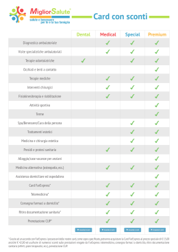
WI connectivity
Connettività WI
Kit WI -Knx
INSTALLATION & USE INSTRUCTIONS
ISTRUZIONI PER L’INSTALLAZIONE ED USO
Avvertenze
Warnings
SAFETY WARNINGS
AVVERTENZE PER LA SICUREZZA
Carefully read this manual before installing or using this device
and keeping it in a place within easy reach.
Le g g e re co n at te n z i o n e q u e s to l i b re t to p r i m a
dell’installazione e/o dell’uso dell’apparecchiatura e
conservarlo in un luogo accessibile.
For further information or requests the Manufacturer’s Technical
Department can be contacted at the phone numbers reported on
the back of this manual.
L’ufficio tecnico del Costruttore si rende disponibile
ai numeri indicati sul retro del presente libretto per
consulenze o richieste tecniche particolari.
•
CAUTION
This system must be installed and repaired by authorized and
qualified staff only.
•
ATTENZIONE
L’installazione e la manutenzione vanno eseguiti solo da
personale qualificato.
GENERAL WARNINGS
AVVERTENZE GENERALI
• If you notice any anomaly after unpacking the component,
please do not use it and contact one of Manufacturer’s
authorized centres.
• Se dopo aver disimballato il componente si nota una
qualsiasi anomalia non utilizzarlo e rivolgersi ad un Centro
di Assistenza autorizzato dal Costruttore.
• Once you have finished the installation, dispose of the
packaging according to the regulations of your country.
• Alla fine dell’installazione smaltire gli imballi secondo quanto
previsto dalle normative in vigore nel Paese di utilizzo.
• Please, use original spare parts only, other the warranty of the
system will decay.
• Esigere solo ricambi originali: la mancata osservazione di
questa norma fa decadere la garanzia.
DISPOSAL
SMALTIMENTO
In accordance with the following European
regulation 2002/95/CE , 2002/96/CE and
2003/108/CE, regarding restrictions on using
dangerous substance in electrical and
electronic devices and general waste disposal
In base a quanto previsto dalle seguenti
direttive europee 2002/95/CE, 2002/96/CE e
2003/108/CE, relative alla riduzione dell’uso
di sostanze pericolose nelle apparecchiature
elettriche ed elettroniche, nonché allo
smaltimento dei rifiuti.
The crossed-out wheeled bin symbol is attached to a product or
its packaging, it means the product must be collected separately
from other waste.
Il simbolo del cassonetto barrato riportato sull’apparecchiatura
indica che il prodotto alla fine della propria vita utile deve essere
raccolto separatamente dagli altri rifiuti.
The user shall give back the device to designated electronic and
electro-technical appliance collection facilities appointed by the
government or the local authorities, or it must be exchanged for a
new, equal-type appliance from the original reseller.
Proper disposal of your old appliance will help prevent potential
negative consequences for the environment and human health
and will favour the recycling of the materials of which the appliance
is composed.
Abusive waste of this product by the user will lead to the application
of administrative sanctions as detailed in the relevant regulations
in force.
L’utente dovrà, pertanto, conferire l’apparecchiatura giunta a
fine vita agli idonei centri di raccolta differenziata dei rifiuti
elettronici ed elettrotecnici, oppure riconsegnarla al rivenditore
al momento dell’acquisto di una nuova apparecchiatura di tipo
equivalente, in ragione di uno a uno.
L’adeguata raccolta differenziata per l’avvio successivo
dell’apparecchiatura dismessa al riciclaggio, al trattamento e allo
smaltimento ambientale compatibile contribuisce ad evitare
possibili effetti negativi sull’ambiente e sulla salute e favorisce
il riciclo dei materiali di cui è composta l’apparecchiatura.
Lo smaltimento abusivo del prodotto da parte dell’utente
comporta l’applicazione delle sanzioni previste dalla vigente
normativa in materia.
2
Index - Indice
Page
Pagina
Descrizione
Description
Warnings
Avvertenze
Safety regulation
3
Avvertenze per la sicurezza
3
General warnings
Avvertenze generali
3
Disposal
Smaltimento
3
Description
Descrizione
3
Contents of the packaging
Contenuto imballo
3
STEP 1
FASE 1
4
Serial card installation
Installazione scheda seriale
STEP 2
4
FASE 2
Control unit configuration checking
5
Verifica configurazione centralina
STEP 3
5
FASE 3
6
Configuration and connection to Konnex network
Configurazione e connessione alla rete Konnex
6
Alarm table
Tabella allarmi
7
DESCRIZIONE
DESCRIPTION
WI-Knx kit is used to inter face WI
thermoregulation units with EIB-Konnex
systems. This includes:
• The serial card which works as “Gateway”
towards systems communicating through EIBKonnex protocol
• The software to control the interfacing for the variables
of the system.
Il Kit WI-Knx ser ve per inter facciare la famiglia di
termoregolazione WI con sistemi EIB-Konnex. Questo prevede:
• L’utilizzo di una scheda seriale che funzionerà da “gateway”
verso sistemi che comunicano tra loro con il protocollo
eib-konnex.
• Lo sviluppo del programma atto a gestire l’interfacciamento
con le variabili del sistema.
Contents of the packaging - Contenuto imballo (COD. 6600093)
OM
Name
Sigla
RDZ code
Codice RDZ
RS-KNX
0660060
Konnex-EIB Serial Card
Scheda seriale Konnex-EIB
0660062
The CD contans the following
technical manual:
1) ModBUS data formats of the
variables of the system;
2) KSetSetup Software;
3) PlugIn for ETS3;
4) Carel Technical Manual.
CD contenente la
documentazione:
1) registri ModBUS delle variabili
del sistema;
2) Software KSetSetup;
3) PlugIn per ETS3;
4) documentazione Carel;
G-IN ET
Tabe
l
B
U
S3
PL
Chart A – Contents of the packaging
Tabella A - Contenuto imballo
CD-KNX
Description
3
Descrizione
registri EV
la
1 Step - Fase
INSTALLATION OF THE SERIAL CARD
INSTALLAZIONE SCHEDA SERIALE
The picture illustrates how to install the
optional serial card into WI-M1 main card with
WI-SA configuration.
Installazione all’interno della scheda
principale WI-M1 nella configurazione WISA della scheda seriale opzionale.
1
2
3
2A
2B
4
5
+
-
4A
AWG 20/22
4B
MASTER
EXTERNAL DEVICE
DISPOSITIVO
ESTERNO
4
2 Step - Fase
CHECKING CONTROL UNIT CONFIGURATION
VERIFICA CONFIGURAZIONE CENTRALINA
Before interfacing, please check the aparameters referring to S1
supervision from the technical menu of the control unit (see WI
technical manual).
Prima di iniziare l’interfacciamento verificare i parametri
riguardanti la supervisione S1 all’interno del menu tecnico della
centralina (menu tecnico WI).
S1 Supervisor
Supervisore S1
SUPERVISORE S1
Num.identif.:001 0
Vel: 19200
Prot:3:ModBus Ext
──────────────────────
Parametri
Serial Card 1
Description
Setting parameters for S1 Serial
card
Descrizione
Impostazioni parametri Seriale S1
ID = Identification Number for
Communication Card
Num. Identif. = identificativo scheda
per comunicazione
Speed = Transferring speed
Vel = velocità di trasferimento
Prot = Communication Protocol
Prot = protocollo di comunicazione
Value
Valore
1
9600
ModBus>Knx
ATTENZIONE
La configurazione soprastante è generica, ciò significa che è
valida per la maggior parte di sistemi di supervisione esterna.
Resta comunque ovvio che per un corretto funzionamento
deve esserci la completa sovrapposizione sui parametri di
connessione dei due sistemi.
IMPORTANT
This is a generic configuration which can be used with most
external supervision systems. Nevertheless, if there are any different
parameters from the above-mentioned configuration, please
change them so that they corresponde.
5
3 Step - Fase
CONFIGURATION AND CONNECTION TO
KONNEX NETWORK
CONFIGURAZIONE E CONNESSIONE ALLA
RETE KONNEX
The electronic card n. 0660060 represents an optional device
through which WI units can be connected with a kind of network
operating according to Konnex standards. Configuring the card
implies the use of ETS3 software, CAREL-plugin-xx.pr4 file and the
KSet tool(it is available on the CD included in the relevant manual
or on the website ksa.carel.com).
La scheda elettronica 0660060 è un dispositivo opzionale che
permette ai sistemi di controllo della linea WI di essere collegati
ad una rete operante secondo lo standard Konnex.
Per la configurazione della scheda è necessario il software ETS3,
il file CAREL-plugin-xx.pr4 ed il tool KSet (disponibile sul CD
allegato alla documentazione o sul sito ksa.carel.com).
Tool
Strumento
Function
Funzione
KSet
Linkage between Modbus® data formats and Konnex
datapoint;
Group address assignation for each datapoint.
Associazione registri Modbus® a datapoint Konnex
Assegnazione indirizzi di gruppo per ogni datapoint
ETS3
Network address assignation;Download .XML file.
Assegnazione indirizzo di rete del dispositivo
1) Create a new project or open an old one.
2)Import the project database CAREL-plugin-xx.pr4 .
3) Set the group addresses for each datapoint.
4) From KSet: open or create new file xxx.XML, set the list
of associations between KNX datapoints and Modbus®
dataformats. In the “groups” column copy the group addresses
set through the ETS3 of the Sharing datapoints and save the
configuration (file .xml).
5) From ETS3:
a) Open ETS3 and add WI device
b) Assign the address to each device by following the standard
steps (press the button on the card, see picture 1).
1)Creare un nuovo progetto o aprire un progetto preesistente.
2) Importare il project database CAREL-plugin-xx.pr4.
3) Definire gli indirizzi di gruppo per tutti i datapoint.
4) Da KSet: aprire o creare un nuovo file xxx.XML, definire la
lista di associazioni tra datapoints KNX e registri Modbus®
riportare nella colonna “gruppi” gli indirizzi di gruppo
impostati tramite ETS3 dei datapoints da condividere e, al
termine, salvare la configurazione (file .xml).
5) Da ETS3:
a) Aprire ETS3 e aggiungere il dispositivo WI
b) Assegnare ad ogni dispositivo l’indirizzo utilizzando la
procedura standard (pressione del pulsantino presente
sulla scheda, vedi figura 1).
Configurare la scheda scaricando il file .XML salvato in
precedenza. Tramite il menù Proprietà del plug-in, selezionare
poi CAREL device configuration.
Configure the card by downloading .XML file saved before. Though
“Properties” Menu of the plug-in, select CAREL device configuration.
Note: For further information, please consult the manual
“Konnex Serial Card.pdf” on the CD.
NB: Per maggiori dettagli consultare il manuale Scheda
Seriale Konnex.pdf presente all’interno del CD.
6
TABELLA ALLARMI
ALARM TABLE
button
bottone
LED
Status
Stato
On steady
Acceso fisso
Red
Rosso
Flashing
Lampeggiante
On steady
Acceso fisso
Green
Verde
Flashing fast
Lampeggiante
veloce
red
rosso
+ -
green
verde
Led meaning
Significato led
Error/solution
Errore/rimedi
No Modbus communication between KNX card and Configuration:
> address incorrect
pCO
> baud rate not correct
> wrong protocol
Errore assenza comunicazione modbus tra scheda Configurazione:
KNX e unità centrale
> Indirizzo unità centrale errato
> Baudrate unità centrale non corretto
> protocollo unità centrale errato
Modbus communication error between KNX card and Modbus exception:
unit control
- the card has been configured with a wrong Modbus or
unsupported addresses
Errore comunicazione modbus tra scheda KNX e unità Modbus exception:
centrale
- la scheda è stata configurata con indirizzi modbus
errati o non supportati
The button has been pressed for the assignment of the
address and the card is awaiting the corresponding
procedure from ETS3
È stato premuto il tasto per l’assegnazione dell’indirizzo
e la scheda è in attesa che da ETS3 si proceda con la
relativa procedura The table has not been loaded, that is, the .XML file
Download the XML table from ETS
- One short fast flash indicates the reception of the address after pressing the button
Non è stata caricata la tabella cioè il file .XML
Scaricare la tabella XML da ETS
- Un lampeggio veloce breve indica la ricezione
dell'indirizzo dopo la pressione del tasto Configuration in progress: ETS3 is downloading the
Flashing slow
XML file
Lampeggiante
lento
Configurazione in corso: ETS3 stà effettuando il
download del file XML No power supply to Konnex Bus
Check: Konnex bus power supply, electrical connections
and polarity of the connections to terminals + and – on
the connector
Green +
Both on steady
Red
Accesi entrambi
Verde +
fissi
Mancanza alimentazione Bus Konnex
Rosso
Verificare: alimentatore bus Konnex, collegamenti
elettrici e polarità connessioni ai morsetti + e - del
connettore.
7
9100211.00 - 06/2011
Scaricare