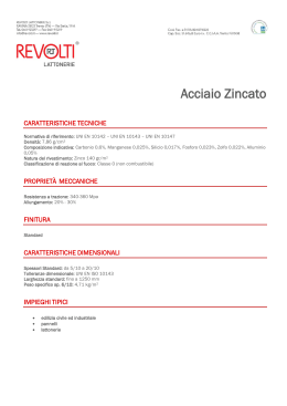
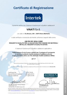
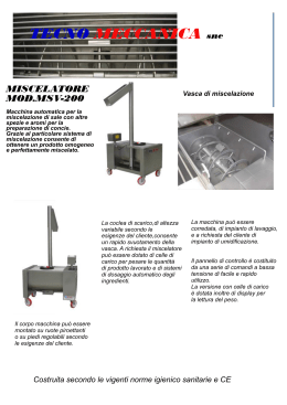
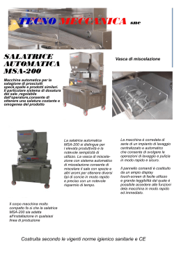
SML-TECNO
I
V. 7.2005
MOTORIDUTTORE ELETTROMECCANICO A GRASSO PER CANCELLI SCORREVOLI
MANUALE ISTRUZIONI E CATALOGO RICAMBI
IL PRESENTE LIBRETTO È DESTINATO AL PERSONALE TECNICO QUALIFICATO ALLE INSTALLAZIONI
F
MOTO-REDUCTEURS ELECTROMECANIQUES A GRAISSE POUR PORTAILS COULISSANTS
NOTICE D'INSTRUCTION ET CATALOGUE PIECES DE RECHANGE
CETTE NOTICE S'ADRESSE À DES TECHNICIENS SPÉCIALISÉS DANS L'INSTALLATION
E
MOTORREDUCTORES ELECTROMECÁNICOS A GRASA PARA CANCELAS CORREDIZAS
MANUAL ISTRUCCIONES Y CATALOGO REPUESTOS
EL PRESENTE FOLLETO ESTÁ DESTINADO AL PERSONAL TÉCNICO ESPECIALIZADO EN INSTALACIONES
GB
D
ELECTROMECHANICAL GEARMOTORS FOR SLIDING GATES
INSTRUCTION HANDBOOK AND SPARE PARTS CATALOGUE
THIS HANDBOOK IS INTENDED FOR QUALIFIED TECHNICAL INSTALLERS
ELEKTROMECHANISCHER GESCHMIERTER GETRIEBEMOTOR FÜR SCHIEBETORE
BEDIENUNGANWEISUNGEN UND ERSATZTEILLISTE
DAS VORLIEGENDE HANDBUCH IST FÜR DAS MIT DER INSTALLATION BETRAUTE TECHNISCH QUALIFIZIERTE FACHPERSONAL BESTIMMT
NL
ELEKTROMECHANISCHE MOTORREDUCTOREN MET VET VOOR SCHUIFPOORTEN
GEBRUIKERSHANDLEIDING EN RESERVEONDERDELEN CATALOGUS
DEZE HANDLEIDING IS BESTEMD VOOR VAKBEKWAME INSTALLATEURS
Te
lco
ma
Telcoma srl - via L. Manzoni, 11 - Z.I. Campidui - 31015 Conegliano - Tv Italy
Tel. 0438-451099 - Fax 0438-451102 - part. IVA 03069910267
http://www.telcoma.it E-mail:[email protected]
I
F
E
MODELLI E CARATTERISTICHE
MODELES ET CARACTERISTIQUES
MODELOS Y CARACTERÍSTICAS
SML 40:
Motoriduttore elettromeccanico irreversibile per
cancelli dal peso max di 800 Kg.
Alimentazione monofase a 230 Vac.
Frizione elettronica.
Pignone a cremagliera verticale M4.
Completo di condensatore, piastra di fissaggio e viti di fissaggio.
TECNO:
Motoriduttore elettromeccanico irreversibile per
cancelli dal peso max di 350 Kg.
Alimentazione a 24 Vac.
Frizione elettronica.
Pignone a cremagliera verticale M4.
Completo di piastra di fissaggio e viti di fissaggio.
SML 40:
Motoréducteur électromécanique irréversible
pour portails d’un poids max. de 800 Kg.
Alimentation monophasée à 230 Vac.
Friction électronique.
Pignon à crémaillère verticale M4.
Doté de condensateur, plaque et vis de fixation.
TECNO:
Motoréducteur électromécanique irréversible
pour portails d’un poids max. de 350 Kg.
Alimentation à 24 Vac.
Friction électronique.
Pignon à crémaillère verticale M4.
Pourvu de plaques et de vis de fixation.
SML 40:
Motorreductor electromecánico para cancelas
de peso máx de 800 Kg.
Alimentación monofásica a 230 Vac.
Fricción electrónica.
Piñón y cremallera vertical M4.
Se entrega con condensador, plancha para la
fijación y tornillos de fijación.
TECNO:
Motorreductor electromecánico para cancelas
de peso máx de 350 Kg.
Alimentación a 24 Vac.
Fricción electrónica.
Piñón y cremallera vertical M4.
Se entrega con plancha y tornillos para su
fijación.
GB
D
NL
MODELS AND CHARACTERISTICS
MODELLE UND KENNDATEN
MODELLEN EN SPECIFICATIES
SML 40:
Irreversible electromechanical gearmotor for
gates with max. weight of 800 kg.
Single-phase power supply of 230 Vac.
Electronic clutch.
Vertical rack and pinion M4.
Complete with capacitor, fixing plate and fixing
screws.
TECNO:
Irreversible electromechanical gearmotor for
gates with max. weight of 350 kg.
Power supply of 24 Vac.
Electronic clutch.
Vertical rack and pinion M4.
Complete with fixing plate and clamping
screws.
SML 40:
Elektromechanischer nicht umkehrbarer
Getriebemotor für Tore mit einem Gewicht von
max. 800 kg.
Einphasen-Versorgung 230 Vac.
Elektronische Kupplung.
Ritzel mit vertikaler Zahnstange M4.
Komplett mit Kondensator, Befestigungsplatte und Befestigungsschrauben.
TECNO:
Elektromechanischer nicht umkehrbarer
Getriebemotor für Tore mit einem Gewicht von
max. 350 kg.
Versorgung 24 Vac.
Elektronische Kupplung.
Ritzel mit vertikaler Zahnstange M4.
Komplett mit Befestigungsplatte und
Befestigungsschrauben.
SML 40:
Elektromechanische onomkeerbare motorreductieaandrijving voor hekken met een max.
gewicht van 800 kg.
Éénfase-voeding van 230 Vac.
Elektronische koppeling.
Tandwiel met een verticale tandheugel M4.
Compleet met condensator, bevestigingsplaat
en bevestigingsschroeven.
TECNO:
Elektromechanische onomkeerbare motorreductieaandrijving voor hekken met een max.
gewicht van 350 kg.
Voeding van 24 Vac.
Elektronische koppeling.
Tandwiel met een verticale tandheugel M4.
Inclusief bevestigingsplaat en bevestigingsschroeven.
I
GUIDA ALL’INSTALLAZIONE
F
GUIDE À L’INSTALLATION
E
GUÍA PARA LA INSTALACIÒN
U.M.
SML 40
TECNO
Kg
800
350
Peso max anta
Poids max vantail
Peso máx puerta
Movimento
Mouvement
Movimiento
(1)
(1)
Centralina elettronica
Centrale électronique
Centralita electrónica
(B)
(B)
Uso
Usage
Uso
(2)
(2)
1) Irreversibile
2) Residenziale/comunità
A) No
B) Si
1) Irréversible
2) résidentiel/collectivité
A) Non
B) Oui
2
1) Irreversible
2) residencial/comunidad
A) No
B) Si
I
DATI TECNICI
E
F
DONNÉES TECHNIQUES
DATOS TÉCNICOS
U.M.
SML 40
TECNO
Vac
230
230
Tensione di linea
Tension de ligne
Tensión de línea
Alimentazione motore
Alimentation moteur
Alimentación motor
/
230Vac
24Vdc
Forza di spinta
Force de poussée
Fuerza de empuje
N
540
480
Corrente max assorbita
Courant max. absorbé
Corriente máx. absorbida
A
2,8
5
Potenza max assorbita
Puissance max. absorbée
Potencia máx. absorbida
W
600
120
Condensatore
Condensateur
Condensador
µF
16
-
Coppia nominale
Couple nominal
Par nominal
Nm
21,6
15
Velocità cancello
Vitesse portail
Velocidad cancela
m/min
10
12
Temperatura di funzionamento
Température de fonctionnement
Temperatura de funcionamiento
-20 +70
-20 +70
Intervento termoprotezione
Intervention thermo-protection
Interv. termoprotección
°C
°C
150
-
Grado di protezione
Degré de protection
Grado de protección
IP
43
43
Grasso
Graisse
Grasa
--
TS 10
TS 10
Intermittenza lavoro
Intermittence de fonctionnement
Intermitencia trabajo
%
40
50
Peso
Poids
Peso
Kg
11
12,5
GB
D
U.M.
SML 40
TECNO
Vac
230
230
TECHNICAL DATA
NL
TECHNISCHE DATEN
TECHNISCHE GEGEVENS
Line voltage
Netzspannung
Leidingspanning
Motor power supply
Versorgung Motor
Motorvoeding
/
230Vac
24Vdc
Thrust force
Hubkraft
Duwkracht
N
540
480
Max. input current
Max. Aufnahmestrom
Max. stroomafname
A
2,8
5
Max. input power
Max. Aufnahmeleistung
Max. opgenomen vermogen
W
600
120
Capacitor
Kondensator
Condensator
µF
16
-
Nominal torque
Nenndrehmoment
Nominale koppel
Nm
21,6
15
Gate speed
Torgeschwindigkeit
Bewegingssnelheid van het hek
m/min
10
12
Operating temperature
Betriebstemperatur
Bedrijfstemperatuur
-20 +70
-20 +70
Thermal cut-off
Überhitzungsschutz
Inschakeling overbelastingsbeveiliging
°C
°C
150
-
Degree of protection
Schutzgrad
Beschermingsgraad
IP
43
43
Grease
Schmierfett
Smeerve
--
TS 10
TS 10
Working intermittence
Arbeitsintermittenz
Intermitterend bedrijf
%
40
50
Weight
Gewicht
Gewicht
Kg
11
12,5
U.M.
SML 40
TECNO
Kg
800
350
GB
INSTALLATION GUIDE
D
NL
INSTALLATIONSANWEISUNGEN LEIDRAAD VOOR DE
INSTALLATIE
Max. single gate weight
Höchstgewicht Torflügel
Max. gewicht vleugel
Movement
Antrieb
Beweging
(1)
(1)
Electronic control unit
Elektronische Steuereinheit
Elektronische besturingskast
(B)
(B)
Use
Anwendung
Gebruik
(2)
(2)
1) Irreversible
2) Residential/communal premises
A) No
B) Yes
1) Selbstverriegelnd
2) Wohngebäude/öffentliche Gebäude
A) Nein
B) Ja
1) Met blokkering (onomkeerbaar)
2) woningen/woonblokken
A) Nee
B) Ja
3
I
F
E
QUADRO D’INSIEME
TABLEAU D’ENSEMBLE
CUADRO DEL CONJUNTO
1.
2.
3.
4.
5.
6.
7.
8.
9.
10.
11.
1.
2.
3.
4.
5.
6.
7.
8.
9.
10.
11.
1.
2.
3.
4.
5.
6.
7.
8.
9.
10.
11.
Linea di alimentazione
Interruttore generale
Interruttore differenziale
Motoriduttore
Antenna
Lampeggiatore
Costola sensibile
Fotocellula
Cremagliera
Staffa di fine corsa
Selettore a chiave
GB
Ligne d’alimentation
Interrupteur général
Interrupteur différentiel
Motoréducteur
Antenne
Clignotant
Tranche de sécurité
Photocellule
Crémaillère
Etrier de fin de course
Sélecteur à clé
D
NL
GENERAL LAYOUT
GESAMTÜBERSICHT
TOTAALBEELD
1.
2.
3.
4.
5.
6.
7.
8.
9.
10.
11.
1.
2.
3.
4.
5.
6.
7.
8.
9.
10.
11.
1.
2.
3.
4.
5.
6.
7.
8.
9.
10.
11.
Power supply line
On/off switch
Differential switch
Gearmotor
Antenna
Flashing light
Sensitive rib
Photocell
Rack
Stop clamp
Key selector
Zufuhrleitung
Hauptschalter
Differentialschalter
Getriebemotor
Antenne
Blinklicht
Kontaktschwelle
Photozelle
Zahnstange
Endschalterbügel
Schlüsselschalter
R
3x1.5
RG58
2x1
4x0.5
2x0.5
3x0.5
4
Línea de alimentación
Interruptor general
Interruptor diferencial
Motorreductor
Antena
Intermitente
Nervio sensibile
Fotocélula
Cremallera
Abrazadera para tope de recorrido
Selector a llave
Voedingslijn
Hoofdschakelaar
Aardlekschakelaar
Motorreductieaandrijving
Antenne
Knipperlicht
Contactdrempel
Fotocel
Tandheugel
Aanslagbeugel
Keuzeschakelaar met sleutel
I
F
E
VERIFICHE PRELIMINARI
CONTROLES PRELIMINAIRES
CONTROLES PRELIMINARES
Prima di passare all’installazione si consiglia
di effettuare le seguenti verifiche ed operazioni:
1. La struttura del cancello deve essere solida ed appropriata.
2. Durante la corsa, il cancello non deve presentare eccessivi sbandamenti laterali.
3. Il sistema ruote/rotaia inferiore e rulli/guida superiore deve funzionare senza eccessivi attriti.
4. Per evitare il deragliamento del cancello devono essere installate le battute di arresto
dello scorrevole, sia in apertura che in chiusura.
5. Nei cancelli preesistenti eliminare l’eventuale serratura manuale.
6. Portare alla base del cancello le canaline
di adduzione dei cavi di alimentazione (Ø
25-50 mm) e di collegamento esterno
(fotocellula, lampeggiatore selettore a chiave, etc.).
Il est conseillé, avant de commencer
l’installation, d’effectuer les contrôles et
opérations qui suivent:
1. La structure du portail doit être solide et
appropriée.
2. Le portail, durant sa course, ne doit pas
présenter d’inclinaisons latérales
excessives.
3. Le système roues/rail inférieur et galets/
glissière supérieur doit fonctionner sans
frottements excessifs.
4. Des butées d’arrêt du cheminement
doivent être installées en ouverture comme
en fermeture afin d’éviter que le portail ne
puisse dérailler.
5. Eliminer des portails déjà existants
l’éventuelle serrure manuelle.
6. Porter à la base du portail les tuyaux
d’adduction des câbles d’alimentation (Ø
25-50 mm) et de raccordement externe
(photocellule, clignotant, sélecteur à clé,
etc.).
Antes de comenzar la instalación, se aconseja
efectuar los siguientes controles y operaciones:
1. La estructura de la cancela tiene que ser
sólida y adecuada.
2. Durante el recorrido, la cancela no tiene
que presentar excesivos desbandes
laterales.
3. El sistema de ruedas/carriles inferior y
rodillos/guía superior tiene que funcionar
sin excesivas fricciones.
4. Para evitar el descarrilamiento de la
cancela, tienen que instalarse los
dispositivos de parada del deslizador, tanto en apertura como cierre.
5. En las cancelas ya existentes, eliminar la
cerradura manual.
6. Llevar a la base de la cancela las canaletas
de aducción de los cables de alimentación
(Ø 25-50 mm) y de conexión externa
(fotocélula, intermitente, selector y llave,
etc.).
GB
D
NL
PRELIMINARY CHECKS
Prior to installation, it is advisable to carry out
the following checks and operations:
1. The gate frame must be sturdy and
suitable.
2. During movement, the gate must not slip
excessively sideways.
3. The wheels/bottom rail and rollers/top track
system must operate without excessive
friction.
4. To prevent the gate from slipping out of the
tracks, stop limits must be installed on the
sliding gate both for opening and closing
operations.
5. Remove any manual lock in existing gates.
6. Take the power supply and the external
connection (photocell, flashing light, key
selector, etc.) cable raceways (Ø 25-50
mm) to the base of the gate.
VORBEREITENDE
ÜBERPRÜFUNGEN
Vor der Installation ist es ratsam, die folgenden
Überprüfungen und Arbeiten durchzuführen:
1. Die Struktur des Tors muß solide und
angemessen sein.
2. Während des Laufs darf das Tor keine
übermäßigen seitlichen Abweichungen
aufweisen.
3. Das System Räder/untere Schiene und
Rollen/obere Führung muß ohne
übermäßige Reibungen funktionieren.
4. Um Entgleisungen des Tors zu vermeiden,
müssen die Anschläge des Läufers sowohl
bei der Öffnung als auch bei der
Schließung installiert sein.
5. Bei bereits bestehenden Toren die
eventuelle manuelle Schließung entfernen.
6. Die Kabelschienen für die Stromkabel (Ø
25-50 mm) und den externen Anschluß
(Photozelle, Blinklicht, Schlüsselschalter,
usw.) unter dem Tor plazieren.
CONTROLES VOORAF
Alvorens tot de installatie over te gaan moeten
de volgende controles en handelingen verricht
worden:
1. De structuur van het hek moet solide en
geschikt zijn.
2. Tijdens het openen en het sluiten mag het
hek niet teveel naar de zijkant overhellen.
3. Het wiel-/railsysteem aan de onderkant en
het rol-/geleidersysteem aan de bovenkant
moeten zonder al teveel wrijving
functioneren.
4. Om te voorkomen dat het hek van de rail
afloopt moeten de aanslagen van het
beweegbare hekgedeelte gemonteerd
worden zodat het hek zowel tijdens het
openen als het sluiten stopt.
5. Bij bestaande hekken moet het met de
hand bediende slot verwijderd worden.
6. Leg aan de onderkant van het hek de
kabelgoten aan waarin u de voedingskabels (Ø 25-50 mm) en de leidingen voor
de externe aansluitpunten (fotocel,
knipperlicht, sleutelschakelaar enz.) moet
laten lopen.
5
I
6
F
E
INSTALLAZIONE
INSTALLATION
INSTALACIÓN
1. Eseguire uno scavo di fondazione, tenendo conto delle misure della contropiastra
di fondazione (Fig. 2).
2. Alloggiare nello scavo le canaline di
adduzione dei cavi di alimentazione e di
collegamento esterno.
3. Annegare nel calcestruzzo le canaline e la
contropiastra di fondazione dopo averne
controllato l’orizzontalità.
Fissare la piastra di ancoraggio in dotazione sulla contropiastra di fondazione con i
dadi forniti e registrare la posizione del
motoriduttore agendo sulle asole della
contropiastra (Fig.1).
Garantire sempre un gioco di 2 mm fra
cremagliera e pignone in modo da non far
gravare il peso del cancello sul
motoriduttore.
Se il cancello è provvisto di un solido
basamento in cemento, il motoriduttore può
essere ancorato direttamente al suolo (senza contropiastra di fondazione) con 4 robusti tasselli ad espansione.
N.B. Rispettare tassativamente le quote di
fig. 3.
1. Creuser les fondations en tenant compte
des mesures de la contre-plaque de
fondation (Fig. 2).
2. Placer dans la tranchée les tuyaux
d’adduction des câbles d’alimentation et de
raccordement externe.
3. Noyer dans le béton, après en avoir
contrôlé l’horizontalité, les tuyaux et la
contre-plaque de fondation.
Fixer, en utilisant les écrous fournis, la
plaque d’ancrage en dotation sur la contreplaque de fondation; régler la position du
motoréducteur en agissant sur les fentes
de la plaque même (Fig. 1).
Assurer toujours un jeu d’2 mm entre la
crémaillère et le pignon de façon à ce que
le poids du portail ne repose pas sur le
motoréducteur.
Si le portail est doté d’un solide
soubassement en ciment, le motoréducteur
peut être ancré directement au sol (sans
contre-plaque de fondation) à l’aide de 4
vis tamponnées robustes.
N.B.: Respecter absolument les cotes de
la Fig. 3.
1. Realizar una excavación de fundación, considerando las medidas de la contraplancha
de fundación (Fig. 2).
2. Colocar en la excavación las canaletas de
aducción de los cables de alimentación y
de conexión externa.
3. Sumergir en el hormigón las canaletas y
la contraplancha de fundación después de
haber controlado la horizontalidad.
Fijar la plancha de anclaje, que viene con
el equipo, sobre la contraplancha de
fundación con las tuercas y registrar la
posición del motorreductor actuando sobre
las ranuras de la misma plancha (Fig. 1).
Garantizar siempre un juego de 2 mm entre
cremallera y piñón, de modo que el peso
de la cancela no caiga sobre el
motorreductor.
Si la cancela tiene una sólida base de cemento, el motorreductor puede anclarse
directamente al suelo (sin contraplancha
de fundación) con 4 gruesos bulones
expansibles.
Nota: Respetar exactamente los niveles de
Fig. 3.
GB
INSTALLATION
1. Make a foundation pit, taking into account
the measurements of the foundation plate
(Fig. 2).
2. Position the raceways for the power supply
and external connection cables in the pit.
3. Check that the raceways and the foundation
plate are level and then bury them in concrete.
Fix the supplied anchoring plate to the
foundation plate with the nuts provided and
adjust the position of the gearmotor by
means of the slots in the same plate
(Fig. 1).
Always make sure that there is a clearance
of 2 mm between the rack and pinion so
that the gate is not resting with all its weight
on the gearmotor.
If the gate is fitted into a solid cement base,
the gearmotor may be anchored directly
to the ground (without foundation plate)
using 4 strong screw anchors.
N.B. The measurements given in Fig. 3
must be observed.
D
INSTALLATION
1. Ein Fundament ausheben, wobei die
Abmessungen der Fundamentgegenplatte
(Abb. 2) zu beachten sind.
2. Die Kabelschienen für das Stromkabel und
den externen Anschluß in dem Aushub
unterbringen.
3. Die Kabelschienen und die Fundamentgegenplatte nach Überprüfung der horizontalen Ausrichtung in den Beton einlassen.
Die mitgelieferte Verankerungsplatte auf
der Fundamentgegenplatte mit Hilfe der
mitgelieferten Mutter befestigen und die
Position des Getriebemotors durch
Betätigung der Löcher der Platte selbst
ausrichten (Abb. 1).
Immer ein Spiel von 2 mm zwischen
Zahnstange und Kolben gewährleisten,
damit das Gewicht des Tors den
Getriebemotor nicht belastet.
Wenn das Tor mit einem soliden Unterbau
aus Zement versehen ist, kann der
Getriebemotor direkt am Boden (ohne
Fundamentsgegenplatte) mit 4 robusten
Spreizdübeln verankert werden.
Hinweis: Unbedingt die Quoten der Abb. 3
beachten.
NL
INSTALLATIE
1. Graaf een funderingsgeul waarbij u
rekening moet houden met de afmetingen
van de tegenfunderingsplaat (fig. 2).
2. Leg de kabelgoten voor de voedingskabels
en de leidingen voor de externe
aansluitpunten in de geul.
3. Controleer of de kabelgoten en de
tegenfunderingsplaat volledig horizontaal
liggen en dek ze vervolgens met beton af.
Maak de meegeleverde verankeringsplaat
met de meegeleverde moeren op de tegenfunderingsplaat vast en stel de positie
van de motorreductieaandrijving af met
behulp van de gleuven die in de plaat zitten
(Fig. 1). Zorg ervoor dat er altijd 2 mm
speling tussen de tandheugel en het
tandwiel zit zodat het gewicht van het hek
geen belasting voor de motorreductieaandrijving vormt.
Als het hek van een solide fundering van
beton voorzien is kan de motorreductieaandrijving rechtstreeks aan de grond
verankerd worden (zonder tegenfunderingsplaat) met 4 stevige expansiepluggen.
N.B. Houd de maten die op fig. 3
aangegeven zijn zorgvuldig aan.
7
MISURE D'INGOMBRO
MESURES D’ENCOMBREMENT
MEDIDAS DEL VOLUMEN
OVERALL DIMENSIONS
AUSSENABMESSUNGEN
MAATSCHETS
R
Fig. 1 / Abb. 1
Fig. 2 / Abb. 2
8
97
210
97
312
40
60
Fig. 3 / Abb. 3
I
F
E
FUNZIONAMENTO MANUALE
FONCTIONNEMENT MANUEL
FUNCIONAMIENTO MANUAL
Per sbloccare il motoriduttore inserire e girare
la chiave, tirare poi la leva dello sportellino
come indicato in fig. 4.
Pour débloquer le moto-réducteur, introduire
la clé puis la tourner. Tirer ensuite la poignée
de la petite porte comme indiqué à la fig. 4.
Para desbloquear el motorreductor, introducir
y girar la llave, tirar después la palanca de la
puertecilla, como indicado en la fig. 4.
GB
D
NL
MANUAL OPERATION
To release the gearmotor, insert the key and
turn it, then pull the lever of the flap as shown
in fig. 4.
MANUELLER BETRIEB
Um den Getriebemotor zu deblockieren, den
Schlüssel einstecken und umdrehen, danach
den Hebel der Luke wie in Abb. 4 ziehen.
Te
HANDMATIGE BEDIENING
Om de motorreductor te ontgrendelen moet u
de sleutel erin steken en draaien, daarna moet
u aan de hendel van de klep trekken zoals
afgebeeld op fig. 4.
lco
ma
Fig. 4 / Abb. 4
9
F
E
FINECORSA
FIN DE COURSE
TOPE DE RECORRIDO
SML 40 / TECNO
Gli SML 40 possono montare il finecorsa meccanico (FCM) o il finecorsa elettronico (FCE).
- Nel Fine corsa meccanico verificare che lo
strisciamento della molla sulla staffa avvenga correttamente. Per piccoli aggiustamenti
intervenire sulla staffa.
- Nel finecorsa elettronico, attenzione che ciascuna staffa con i magneti sia sufficientemente vicina a finecorsa elettronico in modo
da garantire lo stop del motore. La distanza
da tenere tra magnete ed FCE deve essere
compresa fra i 5 e i 10 mm.
CAVI FCE
Giallo (alimentazione 24 V)
Marrone (negativo e comune finecorsa)
Verde/Bianco (contatti finecorsa)
SML 40 / TECNO
Un fin de course mécanique (FCM) ou un fin
de course électronique (FCE) peuvent être
montés sur les SML 40.
- Contrôler sur le fin de course mécanique que
le frottement du ressort sur la pièce d’appui
se produise correctement. Intervenir sur la
pièce d’appui pour les petites mises au point.
- S’assurer sur le fin de course électronique
que chacune des pièces d’appui munies
d’aimants soit suffisamment proche du fin
de course électronique pour garantir l’arrêt
du moteur. La distance à respecter entre
aimant et FCE doit être comprise entre 5 et
10 mm.
CÂBLES FCE
Jaune (alimentation 24V)
Marron (négatif et commun fin de course)
Vert/Blanc (contacts fin de course)
SML 40 / TECNO
En los SML 40 se puede montar el tope de
recorrido mecánico (FCM) o el tope de
recorrido electrónico (FCE).
- En el tope de recorrido mecánico verificar
que el arrastre del resorte sobre la grapa se
efectúe correctamente. Para los pequeños
ajustes, intervenir en la grapa.
- En el tope de recorrido electrónico, poner
atención a que cada grapa con los imanes
esté suficientemente cercana al tope de
recorrido electrónico, con el fin de garantizar
la parada del motor. La distancia que hay
que mantener entre el imán y el FCE debe
estar comprendida entre los 5 y los 10 mm.
CABLES FCE
Amarillo (alimentación 24V)
Marrón (negativo y común tope)
Verde/blanco (contactos topes).
GB
D
NL
I
LIMIT SWITCH
ENDSCHALTER
EINDAANSLAGEN
SML 40 / TECNO
The SML 40 may be fitted with a stop (FCM)
or an electronic limit switch (FCE).
- With the stop, check that the spring slides
correctly along the bracket (band). For small
adjustments, move the bracket.
- With the electronic limit switch, make sure
that each bracket bearing the magnets is
sufficiently near the electronic limit switch in
order to ensure that the motor stops. There
should always be between 5 and 10 mm inclusive between magnet and FCE.
CABLES FCE
Yellow (power 24V)
Brown (negative and common for limit switch)
Green/White (limit switch contacts)
SML 40 / TECNO
Die SML 40 können mit einem mechani-schen
Endschalter (FCM) bzw. einem elektroni-schen
Endschalter (FCE) ausgestattet werden.
- Bei dem mechanischen Endschalter
überprüfen, daß die Feder korrekt auf dem
Bügel gleitet. Für geringfügige Anpassungen
den Bügel betätigen.
- Bei dem elektronischen Endschalter ist
darauf zu achten, daß sich jeder Bügel mit
den Magneten ausreichend nahe an dem
elektronischen Endschalter befindet, so daß
die Stillegung des Motors gewährleistet ist.
Der zwischen Magnet und FCE einzuhaltende Abstand muß zwischen 5 und 10 mm
betragen.
KABELS FCE
Gelb (Stromversorgung 24 Volt)
Braun (Negativ und Allgemein Endschalter)
Grün/Weiß (Endschalterkontakte)
SML 40 / TECNO
Op de SML 40 kan een mechanische
eindaanslag (FCM) of een elektronische
eindaanslag (FCE) worden gemonteerd.
- Bij de mechanische eindaanslag moet u
controleren of de veer goed op de beugel
loopt. U kunt dit door middel van de beugel
een klein beetje afstellen.
- Bij de elektronische eindaanslag moet u erop
letten dat alle beugels met magneten zich
dicht genoeg bij de elektronische
eindaanslag bevinden om stopzetting van de
motor te kunnen waarborgen. De afstand die
tussen de magneet en de FCE aangehouden
moet worden moet tussen de 5 en de 10 mm
liggen.
KABELS FCE
Geel (24V voeding)
Bruin (negatief en nul voor de eindschakelaar)
Groen/wit (contacten voor de eindschakelaar)
10
O
IUS
CH
SA
OR
EC
FIN
E
FIN
TO
ER
AP
SA
R
CO
FCM
FCE
I
F
E
BATTERIE
BATTERIES
BATERÍAS
All’interno del TECNO si trova l’alloggiamento per n. 2 batterie a secco da 12V 1,9
Ah, del tipo rappresentato in figura.
2 batteries à sec de 12V 1,9 Ah, du type
représenté sur le dessin, peuvent être
logées à l’intérieur de TECNO.
En el interior de TECNO se encuentran los
espacios para n. 2 baterías a seco de 12V
1,9 Ah del tipo representado en la figura.
D
NL
GB
BATTERIES
BATTERIEN
BATTERIJEN
Two 12V 1.9 Ah dry batteries, as shown in
the figure, may be housed inside TECNO.
Im Inneren des TECNO befindet sich die
Unterbringung für 2 Trockenbatterien von
12V 1,9 Ah, wie in der Abbildung
angegeben.
In de TECNO is ruimte voor 2 droge
batterijen van 12V 1,9 Ah zoals het type
dat op de figuur is afgebeeld.
11
F
E
MONTAGGIO CREMAGLIERA
MONTAGE CREMAILLERE
MONTAJE CREMALLERA
Sbloccare il motoriduttore nel modo indicato
in Fig. 4 e portare il cancello in completa
aperturata.
Sistemare il motoriduttore con piastra, sulla
contropiastra mediante le apposite viti ed i dadi
in dotazioni.
Appoggiare un elemento di cremagliera al
pignone, e fissare lo stesso con viti e distanziali al cancello.
Spostare manualmente il cancello portando il
pignone in corrispondenza dell’ultimo distanziale. Fissare l’elemento di cremagliera definitivamente.
Per un corretto posizionamento degli altri elementi e garantire la loro rettilineità, è necessario utilizzare un elemento di cremagliera
usandolo come appoggio e riferimento (Fig. 5).
Si deve garantire un’aria fra cremagliera e
pignone di 2 mm così da non far gravare il peso
del cancello sul pignone del motoriduttore
(come in Fig. 6).
Débloquer le motoréducteur (voir “Fonctionnement manuel”) ou placer le portail en position
d’ouverture totale.
Installer le motoréducteur, doté de sa plaque
d’ancrage, sur la contre-plaque de fondation
et le fixer en utilisant les vis et les écrous en
dotation.
Appuyer un élément de crémaillère au pignon
et le fixer au portail à l’aide de vis et
d’entretoises.
Déplacer manuellement le portail afin de faire
correspondre le pignon et la dernière
entretoise.
Fixer définitivement l’élément de crémaillère.
Il est nécessaire d’utiliser un élément de
crémaillère comme appui et point de référence
afin de pouvoir positionner correctement les
autres éléments et de garantir leur alignement
(Fig. 5).
Assurer toujours un jeu d’1 mm entre la
crémaillère et le pignon de façon à ce que le
poids du portail ne repose pas sur le pignon
du motoréducteur (Fig. 6).
Desbloquear el motorreductor (ver
“Funcionamiento manual”) o llevar la cancela
a la completa apertura.
Ubicar el motorreductor, con la plancha de
anclaje, sobre la contraplancha de fundación
y fijarlo usando los tornillos y las tuercas que
vienen con el equipo.
Apoyar un elemento de cremallera al piñón y
fijarlo con tornillos y distanciadores a la
cancela.
Desplazar manualmente la cancela hasta llevar
el piñón a la altura del último distanciador.
Fijar definitivamente el elemento de cremallera.
Para un posicionamiento correcto de los otros
elementos de cremallera y para garantizar su
rectinilidad, es necesario utilizar un elemento
de cremallera como apoyo y referencia (Fig.
5).
Controlar que entre cremallera y piñón exista
un espacio de 1 mm para que el peso de la
cancela no caiga sobre el piñón del
motorreductor (Fig. 6)
I
N.B.
Nel caso di cancelli nuovi verificare in tempi
successivi all’installazione il gioco fra
cremagliera e pignone, se necessario agire
sulle asole della cremagliera per registrare i
giochi.
N.B.
Si le portail est neuf, contrôler, quelque temps
après l’installation, le jeu entre pignon et
crémaillère; si une modification du jeu est
nécessaire agir sur les fentes de la crémaillère.
Nota:
En el caso de cancelas nuevas, controlar,
después de la instalación, el juego entre
cremallera y piñón; si es necesario registrar el
juego de “cremallera/piñón” por medio de las
ranuras de la cremallera.
2mm
Fig. 5 / Abb. 5
12
Fig. 6 / Abb. 6
D
GB
NL
RACK ASSEMBLY
MONTAGE DER - ZAHNSTANGE
DE TANDHEUGEL MONTEREN
Release the gearmotor (see “Manual
operation”) or fully open the gate.
Place the gearmotor complete with anchoring
plate on the foundation plate and fix using the
screws and nuts provided.
Rest a rack element on the pinion and fix it to
the gate using screws and spacers.
Move the gate manually until the pinion is in
line with the last spacer.
Permanently fix the rack element.
A rack element must be used as resting and
reference point in order to position the other
rack elements correctly and make sure they
are in a straight line (Fig. 5).
Make sure that there is a space of 1mm
between the rack and the pinion so that the
weight of the gate does not rest on the
gearmotor pinion (Fig. 6).
Den Getriebemotor deblockieren (siehe
“Manueller Betrieb”) und das Tor vollständig
öffnen.
Den Getriebemotor komplett mit der
Verankerungsplatte auf der Fundamentgegenplatte ausrichten und unter Zuhilfenahme der
mitgelieferten Schrauben und Muttern
befestigen.
Ein Element der Zahnstange an den Kolben
anlegen und mit Schrauben und
Abstandsstücken am Tor befestigen.
Das Tor manuell versetzen, bis daß der Kolben
in Übereinstimmung mit dem letzten
Abstandsstück gebracht ist.
Das Element der Zahnstange definitiv
befestigen.
Für eine einwandfreie Plazierung der anderen
Zahnstangenelemente und um deren
geradlinige Ausrichtung zu gewährleisten, ist
es notwendig, ein Zahnstangenelement als
Auflage und Referenz zu verwenden (Abb. 5).
Sicherstellen, daß zwischen Zahnstange und
Kolben ein Zwischenraum von 1 mm besteht,
so daß das Gewicht des Tors den Kolben des
Getriebemotors nicht belastet (Abb. 6).
Ontgrendel de motorreductieaandrijving (zie
“handbediende werking”) of zet het hek
helemaal open.
Zet de motorreductieaandrijving inclusief de
verankeringsplaat op de tegenfunderingsplaat
en bevestig deze met behulp van de
meegeleverde schroeven en moeren.
Leg een element van de tandheugel op het
tandwiel en maak dit element met schroeven
en afstandshouders aan het hek vast.
Verplaats het hek met de hand totdat het
tandwiel zich ter hoogte van de laatste
afstandshouder bevindt.
Maak het tandheugelelement definitief vast.
Om ervoor te zorgen dat de andere elementen
van de tandheugel op de juiste plaats komen
te zitten en om er zeker van te zijn dat de
elementen recht zitten moet u één
tandheugelelement als steun en als
uitgangspunt nemen (Fig. 5).
Controleer of er tussen de tandheugel en het
tandwiel 1 mm speling zit zodat het gewicht
van het hek geen belasting voor de motorreductieaandrijving vormt (Fig. 6).
N.B.
With new gates, check the backlash or play
between rack and pinion at intervals following
installation and if necessary adjust by means
of the slots in the rack.
Hinweis:
Bei neuen Toren in der Zeit nach der Installation
das Spiel zwischen Zahnstange und Kolben
überprüfen; falls notwendig die Löcher der
Zahnstange betätigen, um das Spiel
„Zahnstange/Kolben” einzustellen.
N.B.
Bij nieuwe hekken moet u na de installatie de
speling tussen de tandheugel en het tandwiel
regelmatig controleren; indien nodig moet u de
speling tussen de tandheugel en het tandwiel
met behulp van de gleuven van de tandheugel
afstellen.
2mm
Fig. 5 / Abb. 5
Fig. 6 / Abb. 6
13
F
E
ANOMALIE E RIMEDI
ANOMALIES ET REMEDES
ANOMALÍAS Y SOLUCIONES
SML
SML
SML
1. Il cancello non apre o non chiude; il motore elettrico non funziona e non si avverte, quindi, alcun rumore o vibrazione.
a. Verificare che la centralina elettronica
sia regolarmente alimentata.
b. Verificare l’efficienza dei fusibili.
c. Verificare l’efficienza del condensatore (per controllare questa condizione
collegare un cond. volante da 16 µF in
parallelo ai fili marrone e nero).
d. Verificare con l’ausilio di adeguati sistemi diagnostici, che le funzioni della
centralina elettronica siano corrette.
e. Accertarsi che il motoriduttore riceva
alimentazione.
2. Il cancello non apre; il motore funziona ma non avviene il movimento.
a. Assicurarsi di aver regolato correttamente il limitatore di coppia sulla
centralina.
b. Verificare che il pignone dentato sia in
presa con la cremagliera.
c. Controllare che il motoriduttore non sia
sbloccato.
d. Può darsi che il motoriduttore sia bloccato da uno dei due arresti meccanici;
in tal caso bisogna sbloccare manualmente il motore, azionare il cancello a
mano, liberandolo da quella posizione
anomala e, prima di ripristinare il funzionamento automatico, posizionare
correttamente le staffe dei fine corsa.
1. Le portail ne s’ouvre pas et ne se ferme pas. Le moteur ne fonctionne pas
et donc aucune rumeur ni vibration ne
peut être perçue.
a. Vérifier que la centrale électronique de
commande soit normalement
alimentée.
b. Vérifier l’état des fusibles.
c. Vérifier que le condensateur
fonctionne. Pour ce faire, relier un
condensateur volant de 16 µF
parallèlement au fil marron et au fil noir.
d. Vérifier, à l’aide d’instruments de
diagnostic adéquats, que les fonctions
de la centrale électronique soient
normales.
e. S’assurer que le motoréducteur est
alimenté.
2. Le portail ne s’ouvre pas, le moteur
fonctionne sans que ne se produise de
mouvement.
a. S’assurer que le limiteur de couple de
la centrale électronique est
correctement réglé.
b. Vérifier que le pignon denté soit en
prise avec la crémaillère.
c. Contrôler que le motoréducteur ne soit
pas en position “manuelle” (débloqué)
d. Contrôler que le motoréducteur ne soit
pas bloqué par un des deux arrêts
mécaniques. Dans ce cas-là, débloquer
manuellement le moteur et actionner
le portail à la main, en le libérant, de
ce fait, de cette position anormale.
Placer correctement les étriers de fin
de course et rétablir le fonctionnement
automatique.
1. La cancela no se abre ni cierra, el motor
no funciona y no se advierte, por lo tanto, ningún ruido o vibración.
a. Controlar que la caja de mandos
electrónica esté regularmente
alimentada.
b. Controlar la eficiencia de los fusibles.
c. Verificar la eficiencia del condensador.
Para controlar esta condición, conectar
un condensador volante de 16 µF en
paralelo a los cables marrón y negro.
d. Verificar, con la ayuda de adecuados
instrumentos diagnósticos; que las
funciones de la caja de mandos
electrónica sean correctas.
e. Asegurarse que el motorreductor
reciba alimentación.
2. La cancela no abre. El motor funciona,
pero no se realiza el movimiento.
a. Asegurarse de haber regulado
correctamente el limitador de par de la
caja de mandos electrónica.
b. Controlar que el piñón dentado
engrane con la cremallera.
c. Controlar que el motorreductor no esté
en posición “manual” (desbloqueado)
d. Controlar que el motorreductor no esté
bloqueado por uno de los dos paros
mecánicos. En tal caso desbloquear
manualmente el motor y accionar la
cancela a mano soltándola, de este
modo, de esta situación anómala.
Posicionar, luego, correctamente las
abrazaderas de los topes de recorrido
y restablecer el funcionamiento
automático.
I
14
GB
MALFUNCTIONING. REMEDIES.
SML
1. The gate neither opens nor closes. The
motor does not work and there is
consequently no noise or vibration.
a. Check that the electronic control unit
is regularly powered.
b. Check the fuses.
c. Check the capacitor by connecting a
loose 16 µF capacitor in parallel to the
brown and black wires.
d. Using suitable diagnostic instruments,
check that the electronic unit is in
proper working order.
e. Make sure that the gearmotor is
powered.
2. The gate does not open. The motor
works but there is no movement.
a. Make sure that the electronic unit
torque limit control is correctly adjusted.
b. Check that the toothed pinion is in mesh
with the rack.
c. Check that the gearmotor is not in the
“manual” position (released).
d. Check that the gearmotor is not locked
in place by one or more mechanical
stops. If it is, release the motor
manually and move the gate by hand
to free it. Finally correct the position of
the stop clamps and reset automatic
operation.
D
NL
STÖRUNGEN
UND DEREN BEHEBUNG
SML
STORINGEN EN OPLOSSINGEN
1. Das Tor öffnet und schließt sich nicht.
Der Motor funktioniert nicht und es ist
daher keinerlei Geräusch oder
Vibration wahrnehmbar.
a. Überprüfen, daß die elektronische
Steuereinheit ordnungsgemäß unter
Spannung steht.
b. Die Leistungsfähigkeit der Sicherungen
überprüfen.
c. Die Leistungsfähigkeit des Kondensators überprüfen. Um diesen Zustand zu
kontrollieren, einen Kondensator von
16 µF parallel an den braunen bzw.
schwarzen Draht anschließen.
d. Mit Hilfe der entsprechenden
Diagnoseinstrumente überprüfen, daß
die Funktionen der elektronischen
Steuereinheit einwandfrei sind.
e. Sicherstellen, daß der Getriebemotor
unter Spannung steht.
2. Das Tor öffnet sich nicht. Der Motor
funktioniert, es erfolgt jedoch keinerlei
Bewegung.
a. Sicherstellen, daß der Drehmomentbegrenzer
der
elektronischen
Steuereinheit korrekt reguliert wurde.
b. Überprüfen, daß der gezahnte Kolben
in die Zahnstange greift.
c. Kontrollieren, daß sich der
Getriebemotor in der “manuellen“
Stellung (deblockiert) befindet.
d. Kontrollieren, daß der Getriebemotor
nicht von einer der beiden
mechanischen
Verriegelungen
blockiert ist. In diesem Fall den Motor
manuell deblockieren und das Tor per
Hand betätigen und aus dieser
anomalen Position befreien. Danach
die Bügel der Endschalter korrekt
positionieren und den Automatikbetrieb
wiederherstellen.
1. Het hek gaat niet open en niet dicht.
De motor functioneert niet en u neemt
dan ook geen enkel geluid of trilling
waar.
a. Controleer of de elektronische
besturingseenheid op correcte wijze
stroom toegevoerd krijgt.
b. Controleer of de zekeringen efficiënt
zijn.
c. Controleer of de condensator efficiënt
is. Om dit te controleren moet u een
losse condensator van 16 µF parallel
aansluiten op de bruine en de zwarte
draad.
d. Controleer met behulp van geschikte
diagnose-apparatuur
of
de
elektronische besturingseenheid goed
functioneert.
e. Controleer of de motorreductieaandrijving stroom toegevoerd krijgt.
2. Het hek gaat niet open. De motor
functioneert, maar er vindt ondanks dat
geen beweging plaats.
a. Controleer of de koppelbegrenzer van
de elektronische besturingseenheid
goed afgesteld is.
b. Controleer of het tandwiel goed in de
tandheugel ingrijpt.
c. Ga na de motorreductieaandrijving niet
op de “handbedieningsstand” staat
(ontgrendeld is).
d. Ga na dat de motorreductieaandrijving
niet geblokkeerd is door één van de
mechanische aanslagen. In dat geval
moet u de motor met de hand
deblokkeren en het hek met de hand
in werking stellen en uit deze
abnormale stand bevrijden. Zet de
beugels van de aanslagen daarna in
de goede stand en herstel de
automatische werking.
SML
15
F
E
ANOMALIE E RIMEDI
ANOMALIES ET REMEDES
ANOMALÍAS Y SOLUCIONES
TECNO
TECNO
TECNO
1. Il cancello non apre o non chiude; il motore elettrico non funziona e non si avverte, quindi, alcun rumore o vibrazione.
a. Verificare che la centralina elettronica
sia regolarmente alimentata.
b. Verificare l’efficienza dei fusibili.
c. Verificare che tutti i LED relativi ai contatti NC della centralina elettronica siano accesi, e che i LED relativi ai contatti NA siano spenti.
d. Verificare con l’ausilio di adeguati sistemi diagnostici, che le funzioni della
centralina elettronica siano corrette.
e. Accertarsi che il motoriduttore riceva
alimentazione.
2. Il cancello non apre; il motore funziona ma non avviene il movimento.
a. Assicurarsi di aver regolato correttamente il limitatore di coppia sulla
centralina.
b. Verificare che il pignone dentato sia in
presa con la cremagliera.
c. Controllare che il motoriduttore non sia
sbloccato.
d. Può darsi che il motoriduttore sia bloccato contro le battute di arresto del cancello. In tal caso bisogna sbloccare manualmente il motore, azionare il cancello a mano, liberandolo da quella posizione anomala, ribloccare e dare un
nuovo comando alla centralina elettronica.
1. Le portail ne s’ouvre pas et ne se ferme pas. Le moteur ne fonctionne pas
et donc aucune rumeur ni vibration ne
peut être perçue.
a. Vérifier que la centrale électronique de
commande soit normalement
alimentée.
b. Vérifier l’état des fusibles.
c. Vérifier que tous les voyants lumineux
relatifs aux contacts NF de la centrale
électronique soient allumés et que les
voyants lumineux relatifs aux contacts
NO soient éteints.
d. Vérifier, à l’aide d’instruments de
diagnostic adéquats, que les fonctions
de la centrale électronique soient
normales.
e. S’assurer que le motoréducteur est
alimenté.
2. Le portail ne s’ouvre pas, le moteur
fonctionne sans que ne se produise de
mouvement.
a. S’assurer que le limiteur de couple de
la centrale électronique est
correctement réglé.
b. Vérifier que le pignon denté soit en
prise avec la crémaillère.
c. Contrôler que le motoréducteur ne soit
pas en position “manuelle” (débloqué)
d. Le moto-réducteur peut être bloqué
contre les butées d’arrêt du portail.
Dans ce cas-là, débloquer le moteur
puis actionner le portail à la main en le
libérant de cette position anormale. Le
bloquer de nouveau et donner une
nouvelle commande à la centrale
électronique.
1. La cancela no se abre ni cierra, el motor
no funciona y no se advierte, por lo tanto, ningún ruido o vibración.
a. Controlar que la caja de mandos
electrónica esté regularmente
alimentada.
b. Controlar la eficiencia de los fusibles.
c. Controlar que todos los INDICADORES LUMINOSOS relativos a los
contactos NC del centralita electrónico
estén encendidos, y que los INDICADORES LUMINOSOS relativos a los
contactos NA estén apagados.
d. Verificar, con la ayuda de adecuados
instrumentos diagnósticos; que las
funciones de la caja de mandos
electrónica sean correctas.
e. Asegurarse que el motorreductor
reciba alimentación.
2. La cancela no abre. El motor funciona,
pero no se realiza el movimiento.
a. Asegurarse de haber regulado
correctamente el limitador de par de la
caja de mandos electrónica.
b. Controlar que el piñón dentado
engrane con la cremallera.
c. Controlar que el motorreductor no esté
en posición “manual” (desbloqueado).
d. Puede ocurrir que el motorreductor se
bloquee contra los batientes de parada
de la cancela. En tal caso es necesario
desbloquear manualmente el motor,
accionar la cancela a mano, liberándolo
de esa posición anómala, volver a
bloquear y dar un nuevo mando al
centralita electrónico.
I
16
GB
MALFUNCTIONING.REMEDIES.
TECNO
1. The gate neither opens nor closes. The
motor does not work and there is
consequently no noise or vibration.
a. Check that the electronic control unit
is regularly powered.
b. Check the fuses.
c. Check that all the indicator lights related
to the NC contacts of the electronic
control unit are on and that those
related to the NO contacts are off.
d. Using suitable diagnostic instruments,
check that the electronic unit is in
proper working order.
e. Make sure that the gearmotor is
powered.
2. The gate does not open. The motor
works but there is no movement.
a. Make sure that the electronic unit
torque limit control is correctly adjusted.
b. Check that the toothed pinion is in mesh
with the rack.
c. Check that the gearmotor is not in the
“manual” position (released).
d. It is possible that the gearmotor is
jammed against the gate stop limits. If
so, the motor must be released
manually. Move the gate manually,
freeing it from the anomalous position,
re-lock and send a new command to
the electronic control unit.
D
NL
BETRIEBSSTÖRUNGEN
UND DEREN BEHEBUNG.
TECNO
STORINGEN EN OPLOSSINGEN.
1. Das Tor öffnet und schließt sich nicht.
Der Motor funktioniert nicht und es ist
daher keinerlei Geräusch oder
Vibration wahrnehmbar.
a. Überprüfen, daß die elektronische
Steuereinheit ordnungsgemäß unter
Spannung steht.
b. Die Leistungsfähigkeit der Sicherungen
überprüfen.
c. Überprüfen, daß alle Leuchtdioden der
normalerweise
geschlossenen
Kontakte der elektronischen
Steuereinheit eingeschaltet und die
Leuchtdioden der normalerweise
offenen Kontakte ausgeschaltet sind.
d. Mit Hilfe der entsprechenden
Diagnoseinstrumente überprüfen, daß
die Funktionen der elektronischen
Steuereinheit einwandfrei sind.
e. Sicherstellen, daß der Getriebemotor
unter Spannung steht.
2. Das Tor öffnet sich nicht. Der Motor
funktioniert, es erfolgt jedoch keinerlei
Bewegung.
a. Sicherstellen, daß der Drehmomentbegrenzer
der
elektronischen
Steuereinheit korrekt reguliert wurde.
b. Überprüfen, daß der gezahnte Kolben
in die Zahnstange greift.
c. Kontrollieren, daß sich der
Getriebemotor in der „manuellen“
Stellung (deblockiert) befindet.
d. Es kann sein, daß sich der Getriebemotor an den Endanschlägen des Tors
blockiert. In diesem Fall ist es
notwendig, den Motor manuell zu
deblockieren, das Tor per Hand zu
betätigen, es aus der anomalen
Position zu befreien, wieder zu
blockieren und der elektronischen
Steuereinheit einen neuen Befehl zu
erteilen.
1. Het hek gaat niet open en niet dicht.
De motor functioneert niet en u neemt
dan ook geen enkel geluid of trilling
waar.
a. Controleer of de elektronische
besturingseenheid op correcte wijze
stroom toegevoerd krijgt.
b. Controleer of de zekeringen efficiënt
zijn.
c. Controleer of alle LED’s van de
contacten NC (maakcontacten) van de
elektronische besturingskast branden
en of alle LED’s van de contacten NO
(verbreekcontacten) uit zijn.
d. Controleer met behulp van geschikte
diagnose-apparatuur
of
de
elektronische besturingseenheid goed
functioneert.
e. Controleer of de motorreductieaandrijving stroom toegevoerd krijgt.
2. Het hek gaat niet open. De motor
functioneert, maar er vindt ondanks dat
geen beweging plaats.
a. Controleer of de koppelbegrenzer van
de elektronische besturingseenheid
goed afgesteld is.
b. Controleer of het tandwiel goed in de
tandheugel ingrijpt.
c. Ga na de motorreductieaandrijving niet
op de “handbedieningsstand” staat
(ontgrendeld is).
d. Het kan gebeuren dat de motorreductor
tegen de aanslagen van de poort
vergrendeld is. In dat geval moet u de
motor met de hand ontgrendelen, de
poort met de hand in werking stellen
en uit deze abnormale stand halen, de
motor opnieuw vergrendelen en een
nieuwe opdracht aan de elektronische
besturingskast geven.
TECNO
17
I
F
E
AVVERTENZE IMPORTANTI
SULL’INSTALLAZIONE
AVERTISSEMENTS IMPORTANTS
CONCERNANT L’INSTALLATION
ADVERTENCIAS IMPORTANTES
SOBRE LA INSTALACION
1. L’installazione dell’automazione deve
essere eseguita a regola d’arte da
personale qualificato avente i requisiti di
legge e fatta in conformità della direttiva
macchine 98/37/CE e alle normative
EN13241-1, EN 12453 e EN 12445.
2. Verificare la solidità delle strutture
esistenti (colonne, cerniere, ante) in
relazione alle forze sviluppate dal
motore.
3. Verificare che vi siano dei fermi meccanici di adeguata robustezza a fine apertura
e fine chiusura delle ante.
4. Verificare lo stato di eventuali cavi già
presenti nell’impianto.
5. Fare un’analisi dei rischi dell’automazione e di conseguenza adottare le sicurezze e le segnalazioni necessarie.
6. Installare i comandi (ad esempio il
selettore a chiave) in modo che
l’utilizzatore non si trovi in una zona
pericolosa.
7. Terminata l’installazione provare più volte
i dispositivi di sicurezza, segnalazione e
di sblocco dell’automazione.
8. Applicare sull’automazione l’etichetta o la
targhetta CE contenenti le informazioni di
pericolo e i dati di identificazione.
9. Consegnare all’utilizzatore finale le
istruzioni d’uso, le avvertenze per la
sicurezza e la dichiarazione CE di
conformità.
10. Accertarsi che l’utilizzatore abbia
compreso il corretto funzionamento
automatico, manuale e di emergenza
dell’automazione.
11. Informare l’utilizzatore per iscritto (ad
esempio nelle istruzioni d’uso) :
-dell’eventuale presenza di rischi residui
non protetti e dell’uso improprio
prevedibile.
-Di scollegare l’alimentazione quando
viene eseguita la pulizia nell’area
dell’automazione o viene fatta piccola
manutenzione (es: ridipingere).
-Di controllare frequentemente che non vi
siano danni visibili all’automazione e nel
caso ve ne siano, avvertire immediatamente l’installatore
-Di non far giocare i bambini nelle
immediate vicinanze dell’automazione
12. Predisporre un piano di manutenzione
dell’impianto (almeno ogni 6 mesi per le
sicurezze) riportando su di un apposito
registro gli interventi eseguiti.
1.
L’installation de l’automation doit être effectuée dans les règles de l’art par du personnel
spécialisé, conformément aux dispositions légales, à la directive machine 98/37/CE et aux
normes EN 12453 et EN 12445.
2. S’assurer que les structures existantes (colonnes, charnières, vantaux) soient suffisamment solides pour résister aux forces développées par le moteur.
3. S’assurer que les arrêts mécaniques en fin
d’ouverture et en fin de fermeture des vantaux soient suffisamment robustes.
4. Vérifier l’état des câbles qui se trouvent éventuellement déjà dans l’installation
5. Faire une analyse des risques de l’automation et adopter, en fonction de celle-ci, les dispositifs de sécurité et de signalisation nécessaires.
6. Installer les commandes (par exemple le sélecteur à clé) de manière à ce que l’utilisateur ne se trouve pas dans une zone dangereuse.
7. Une fois l’installation terminée, tester plusieurs fois les dispositifs de sécurité, de signalisation et de déverrouillage de l’automation.
8. Appliquer sur l’automation l’étiquette ou la
plaque CE où sont indiqués les dangers présentés par l’automation ainsi que les données
d’identification de la machine.
9. Remettre à l’utilisateur final le mode d’emploi, les avertissements concernant la sécurité et la déclaration CE de conformité.
10. S’assurer que l’utilisateur a bien compris le
fonctionnement automatique, manuel et d’urgence de l’automation.
11. Informer l’utilisateur par écrit (par exemple
dans le mode d’emploi) :
-de la présence éventuelle de risques
résiduels non protégés et de l’usage
impropre prévisible.
-De la nécessité de couper l’alimentation
quand le nettoyage de la zone de l’automatisme a lieu ou en cas de petites interventions de maintenance (ex. repeindre).
-De la nécessité de contrôler fréquemment
l’absence de dommages visibles à
l’automatisme et s’il y en a, avertir immédiatement l’installateur.
-Qu’il ne faut pas laisser les enfants jouer à
proximité de l’automatisme.
12. Etablir un plan de maintenance de l’installation (au moins tous les 6 mois pour les dispositifs de sécurité) en inscrivant sur un registre prévu à cet effet les interventions effectuées.
1. La instalación del automatismo debe ser
realizada según los cánones, por personal
cualificado que reúna los requisitos establecidos por la ley y de conformidad con la
Directiva sobre máquinas 98/37/CE y con
las normas EN 12453 y EN 12445.
2. Compruebe la solidez de las estructuras
existentes (columnas, bisagras, hojas) en
relación con las fuerzas desarrolladas por
el motor.
3. Controle que haya retenes mecánicos de
solidez adecuada en los puntos de fin de
apertura y de fin de cierre de las hojas.
4. Controle el estado de los cables ya
existentes en la instalación, en su caso.
5. Haga un análisis de los riesgos del automatismo y adopte los dispositivos de seguridad y las señalizaciones necesarias en
consecuencia.
6. Instale los mandos (por ejemplo, el selector
de llave) de manera que el usuario no se
encuentre en una zona peligrosa.
7. Terminada la instalación, pruebe varias veces los dispositivos de seguridad, señalización y desbloqueo del automatismo.
8. Aplique en el automatismo una etiqueta o
una placa CE que contenga las informaciones de peligro y los datos de identificación.
9. Entregue al usuario final las instrucciones
para el uso, las advertencias para la seguridad y la declaración CE de conformidad.
10. Asegúrese de que el usuario haya comprendido el correcto funcionamiento automático, manual y de emergencia del automatismo.
11. Informe al usuario por escrito (por
ejemplo en las instrucciones de uso) :
-sobre la presencia de riesgos residuales
no protegidos y sobre el uso inadecuado
previsible.
-que debe desconectar la alimentación
cuando hace la limpieza en la zona de la
automatización o si hace un pequeño
mantenimiento (ej.: pintar).
-que debe controlar a menudo que la
automatización no presente daños
visibles y, en el caso de que los haya,
deberá advertir de inmediato al instalador
-que no debe permitir que los niños
jueguen en las cercanías de la
automatización
12. Predisponga un programa de mantenimiento de la instalación (al menos cada 6 meses para los dispositivos de seguridad), anotando en un registro expresamente dedicado las intervenciones realizadas.
ELIMINATION
Ce produit est constitué de divers composants
qui pourraient à leur tour contenir des substances polluantes. Ne pas laisser ce produit
gagner l’environnement.
S’informer sur le système de recyclage ou
d’élimination du produit conformément aux
dispositions légales en vigueur à un niveau
local.
ELIMINACION
Este producto está constituido por varios
componentes que podrían, a su vez, contener sustancias contaminantes. ¡No los vierta en el medio ambiente!
Infórmese sobre el sistema de reciclaje o
eliminación del producto con arreglo a las
leyes vigentes en ámbito local.
SMALTIMENTO
Questo prodotto è formato da vari
componenti che potrebbero a loro volta
contenere sostanze inquinanti. Non
disperdere nell’ambiente!
Informarsi sul sistema di riciclaggio o
smaltimento del prodotto attenendosi alle
norme di legge vigenti a livello locale.
18
GB
IMPORTANT RECOMMENDATIONS
CONCERNING INSTALLATION
D
WICHTIGE
INSTALLATIONSHINWEISE
NL
BELANGRIJKE AANWIJZINGEN
M.B.T. DE INSTALLATIE
1. Only qualified personnel having the legal
requirements must install the automation
according to the principles of good
workmanship and in conformity with the
machinery directive 98/37/CE and
standards EN 12453 and EN 12445.
2. Check that the existing structures (posts,
hinges, leaves) are stable in relation to
the forces developed by the motor.
3. Check that suitably robust limit stops
have been installed for end of gate
opening and closing.
4. Check the state of the cables that are
already present in the system.
5. Analyse the hazards connected with the
automation system and adopt the
necessary safety and signalling devices
accordingly.
6. Install the commands (e.g. the key
selector) so that the user is not placed in
a hazardous area when using them.
7. Upon completion of the installation, test
the safety, signalling and release devices
of the automation system several times.
8. Apply the CE label or plate with information regarding the hazards and identification data on the automation.
9. Give the end user the instructions for
use, the safety recommendations and the
CE declaration of conformity.
10. Ensure that the user has understood the
correct automatic, manual and emergency operation of the automation
system.
11. Inform the user in writing (in the use
instructions for example):
-Of possible non secluded residual risks
and of foreseeable improper use.
-To disconnect the power supply when
cleaning the area that is automated or
when performing small maintenance
operations (e.g.: repainting).
-To frequently control that no visible
damage has occurred to the automation,
and to inform the installer immediately if
damage is noticed.
-Not to allow children to play in the
vicinity of the automation.
12. Prepare a maintenance schedule for the
automation installation (at least once
every 6 months for the safety devices),
recording the work carried out in a
special book.
1. Die Installation der Automatisierung muss in
Übereinstimmung mit der Maschinenrichtlinie 98/
37/EU und den Bestimmungen EN 12453 und
EN 12445, fachgerecht und von qualifiziertem
Personal, das die gesetzlichen Anforderungen
erfüllt, vorgenommen werden.
2. Die Stabilität der vorhandenen Strukturen (Säulen, Scharniere, Flügel) im Hinblick auf die vom
Motor entwickelten Kräfte überprüfen.
3. Sicherstellen, dass am Öffnungsanschlag und
am Schließanschlag der Torflügel ausreichend
robuste mechanische Feststellvorrichtungen
vorhanden sind.
4. Den Zustand eventueller, bereits in der Anlage
vorhandener Kabel überprüfen.
5. Die Risiken, die durch die Automatisierung entstehen können, abwägen und dementsprechende Sicherheitsvorkehrungen treffen, sowie die erforderlichen Warnhinweise anbringen.
6. Die Steuerungen (z.B. Schlüsselschalter) so installieren, dass sich der Benutzer nicht in einem
Gefahrenbereich aufhalten muss.
7. Nach abgeschlossener Installation mehrmals die
Sicherheits-,
Anzeigeund
Entsperrvorrichtungen der Automatisierung erproben.
8. Auf der Automatisierung die EU- Etikette oder
das EU-Schild anbringen, auf dem die Gefahrenhinweise und die Kenndaten aufgeführt sind.
9. Dem Endkunden die Bedienungsanweisung, die
Sicherheitshinweise und die EU-Konformitätserklärung aushändigen.
10. Sicherstellen, dass der Bediener die korrekte
automatische und manuelle Funktionsweise sowie den Notbetrieb der Automatisierung verstanden hat.
11. Den Benutzer schriftlich (z.B. in den Bedienungsanleitungen) über folgendes informieren:
-eventuelles Vorhandensein nicht geschützter
Restrisiken; vorhersehbarer unsachgemäßer
Gebrauch
-Vorschrift, die Stromversorgung abzutrennen,
wenn im Bereich der Automatisierung gereinigt
wird oder kleine Instandhaltungen ausgeführt
werden (wie z.B. neuer Anstrich)
-dass er die Automatisierung häufig auf
sichtbare Schäden zu überprüfen und ggf.
unverzüglich den Installateur zu benachrichtigen hat
-dass Kinder nicht in der unmittelbaren Nähe
der Automatisierung spielen dürfen.
12. Einen Wartungsplan für die Anlage vorbereiten
(die Sicherheitsvorrichtung müssen mindestens
alle 6 Monate gewartet werden) und die ausgeführten Wartungseingriffe in einem entsprechenden Verzeichnis anmerken.
1. De installatie van de automatisering moet op deugdelijke wijze uitgevoerd worden door vakmensen
die aan de wettelijke eisen voldoen en moet in
overeenstemming zijn met de Machinerichtlijn 98/
37/EG en de normen EN 12453 en EN 12445.
2. Er moet gecontroleerd worden of de bestaande
constructie-elementen (zuilen, scharnieren, vleugels) stevig zijn met het oog op de kracht die door
de motor ontwikkeld wordt.
3. Er moet gecontroleerd worden of er aan het
einde van de opening en aan het einde van de
sluiting van de vleugels mechanische stops zijn
die stevig genoeg zijn.
4. Controleer de staat van de kabels die eventueel
reeds in de installatie aanwezig zijn.
5. Er moet een risicoanalyse van de automatisering
gemaakt worden en op basis daarvan moeten de
nodige veiligheids- en waarschuwingssystemen
toegepast worden.
6. De bedieningselementen (bijv. de sleutelschakelaar) moeten zodanig geïnstalleerd worden
dat de gebruiker zich niet op gevaarlijke plaatsen
bevindt.
7. Na afloop van de installatie moeten de veiligheids, waarschuwings- en ontgrendelsystemen van de
automatisering diverse keren getest worden.
8. Op de automatisering moet het CE-etiket of het
CE-plaatje met informatie over de gevaren en de
typegegevens aangebracht worden.
9. De gebruiksaanwijzing, de veiligheidsvoorschriften en de EG-verklaring van overeenstemming moeten aan de eindgebruiker gegeven
worden.
10. Er moet nagegaan worden of de gebruiker de
juiste automatische, handbediende en noodwerking van de automatisering begrepen heeft.
11. Informeer de gebruiker schriftelijk (bijvoorbeeld
in de aanwijzingen voor gebruik) ten aanzien
van het volgende:
-eventueel nog aanwezige niet-beveiligde
restrisico’s en voorspelbaar oneigenlijk gebruik.
-de stroomtoevoer los te koppelen wanneer er
schoonmaakwerkzaamheden in de zone
rondom de automatisering worden verricht of
klein onderhoud (bijvoorbeeld: schilderwerk).
-dikwijls te controleren dat er geen zichtbare
schade aan de automatisering is, en indien die
er is, onmiddellijk de installateur te
waarschuwen
-geen kinderen in de onmiddellijke nabijheid van
de automatisering te laten spelen
12. Er moet een onderhoudsplan van de installatie
opgesteld worden (minimaal om de 6 maanden
voor de beveiligingen) waarbij de uitgevoerde
werkzaamheden in een speciaal register genoteerd moeten worden.
DISPOSAL
This product is made up of various
components that could contain pollutants.
Dispose of properly!
Make enquiries concerning the recycling
or disposal of the product, complying with
the local laws in force.
ENTSORGUNG
Dieses Produkt besteht aus verschiedenen Bauteilen, die ihrerseits die Umwelt verschmutzende Stoffe enthalten können. Sachgerecht entsorgen!
Informieren Sie sich, nach welchem Recyclingoder Entsorgungssystem das Produkt
entsprechend der örtlich geltenden Bestimmungen zu entsorgen ist.
VERWIJDERING
Dit product bestaat uit diverse onderdelen die ook
weer verontreinigende stoffen kunnen bevatten.
Het product mag niet zomaar weggegooid worden!
Informeer over de wijze van hergebruik of verwijdering van het product en neem daarbij de wettelijke voorschriften die ter plaatse gelden in acht.
19
SML
7
6
5
4
3
8
17
9
18
10
11
12
13
14
38
26
42
37
36
35
29
20
31
34
32
33
19
20
21
22
2
23
1
24
15
16
25
26
42
40
27
28
29
41
39
30
21
I
Nr
1
2
3
4
5
6
7
8
9
10
11
12
13
14
15
16
17
18
19
20
21
22
23
24
25
26
27
28
29
30
31
32
33
34
35
36
37
38
39
40
41
42
22
Cod.
Distinta base SML
Coperchio SM serig. TELCOMA lav.
Vite M3.9x13 UNI 6955 A2 inox
Centralina elettronica T100
Vite M4x8 trilobata TPS+ zinc.
Supporto per centralina CRC
Cond. Poli 16µF 450V cavo
Fascetta elastica L=178
Pressacavo PG9
Tappo per calotta SML D.28x1.2
Tappo per calotta SML D.25x1
Calotta + statore SML 40
Vite M6x20 TCCE trilobata zinc.
O.Ring D.110.72x3.53 n. 4437
Cuscinetto D.17x40x12 n. 6203 2RS
Spina elastica D.6x35 UNI 6873
Vite senza fine per alb. motore SML
Vite M4x6 trilobata TC+ zinc.
Fastom ad occhiello D.5.2
Albero Motore per SML 40
Disco premigrasso SML 40
Cuscinetto D.20x47x14 n. 6204 ZZ
Corpo riduttore per SM
Vite M4x6 trilobata TC+ zinc.
Sportellino di sblocco e serr. SM-SML
Vite M5x10 trilobata TC+ zinc.
Cuscinetto D.25x47x12 6005
Perno di sblocco sportellino SM/SML
Molla di sblocco per SM 10x48
Anello seeger D.25 UNI 7435
SEG25EF
Corona dentata con chiavetta SML
COR0005
Distanziale blocca corona SM/SML
DIS0003
Linguetta 10x8x50 UNI 6604
LI10X08X050
Albero condotto con chiavetta SM/SML
ALBC20Z
Linguetta 8x7x15 UNI 6604
LI08X07X015
Pignone dentato per SM
PIGN20M418Z
Flangia anteriore per SM ver.
FLA20V
OR098M02X03M53 O. ring D.98.02 x3.53 n. 4387
VTT060X0150SZC Vite M6x15 trilobata TPS+ zinc.
Passacavo GW50428 per separè
PASF20
VTM060X0300CZCE Vite M6x30 UNI 5931 TCCE zinc
Separè per SM-SML
9262011400
Paraolio D.25x40x7
PA25X40X7BA
COPSMSER
VTA039X0130SIC
T100SS
VTT040X0080SZC
SUP00150
9422516000
FAS178X00E
9362000000
TAP0014
TAP0003
STAT30A
VTT060X0200CICE
OR110M72X03M53
CUSC62032RSA
SPIE06X035G
9230002900
VTT040X0060CZC
FST5M2VP
ALBR30D
9262011000
CUSC6204ZZA
CORC20V
VTT040X0060CZC
SPSA
VTT050X0100CZC
CUSC60052RSA
PE0023
MOS2010X38
A
CAL300A
B
ALBC30D
C
ALBV30D
F
Liste base SML
Couvercle SM TELCOMA
Vis M3.9x13 UNI 6955 A2 inox
Centrale électronique T100
Vis M4x8 trilobée TPS + Zn
Support centrale CRC
Condensateur 16 µF 450 V
Petite bande élastique L.178
Presse-câble PG9
Bouchon pour calotte SML D.28x1.2
Bouchon calotte SML D.25x1
Calotte + stator SML 40
Vis M6x20 trilobée TCCE zinc.
O.Ring D.110.72x3.53 n. 4437
Coussinet D.17x40x12 n. 6203 2RS
Fiche élastique D.6x35 UNI 6873
Vis sans fin pour arbre motor SML
Vis M4x6 trilobée + Zn
Faston à oeillet D.5.2
Arbre moteur pour SML 40
Disque presse-graisse SML 40
Coussinet D.20x47x14 n. 6204 ZZ
Corps réducteur pour SM
Vis M4x6 trilobée TC + Zn
Petite porte de déverrouillage et serrure
Vis M5x10 trilobée TC + Zn
Coussinet D.25x47x12 6005
Pivot de déblocage petite porte SM/SML
Ressort de déblocage pour SM 10x48
Anneau SEEGER D.25 UNI 7435
Couronne dentée avec clavette SML
Entretoise de blocage de la couronne SML
Languette 10x8x50 UNI 6604
Arbre entraîné avec clavette SM/SML
Languette 8x7x15 UNI 6604
Pignon denté pour SM
Bride avant pour SM peinte
O. ring D.98.02 x3.53 n. 4387
Vis M6x15 trilobée TPS + Zn
Passage câble GW50428 pour separè
Vis M6x30 UNI 5931 TCCE Zn
Elément de séparation pour SM-SML
Pare-huile D.25x40x7
E
Lista de materiales SML
Tapa SM TELCOMA
Tornillo M3,9x13 UNI 6955 A2
Central electrónica T100
Tornillo M4x8 trilobulado TPS + Zn
Soporte caja de mandos CRC
Condensador 16 µF 450 V
Abrazadera élastica L.178
Prensacables PG9
Tapón para casquete SML D.28x1.2
Tapón para casquete SML D.25x1
Casquete + estator SML 40
Tornillo M6x20 trilobulado TCCE zinc.
O.Ring D.110.72x3.53 n. 4437
Cojinete D.17x40x12 n. 6203 2RS
Clavija elástica D.6x35 UNI 6873
Tornillo sinfin para arbol motor SM
Tornillo M4x6 trilobulado TC + Zn
Faston con ojal D.5.2
Arbol motor para SML 40
Disco de protección contra la grasa SML
Cojinete D.20x47x14 n. 6204 ZZ
Cuerpo reductor para SM
Tornillo M4x6 trilobulado TC + Zn
Puerta de desbloqueo y cerradura SM-SML
Tornillo M5x10 trilobulado TC + Zn
Cojinete D.25x47x12 6005
Perno que desbloque puerta SM/SML
Resorte para desbloqueo para SM 10x48
Anillo SEEGER D.25 UNI 7435
Corona dentada con chaveta SML
Distancial bloquea corona SM/SML
Lengüeta 10x8x50 UNI 6604
Eje accionado con chaveda SM/SML
Lengüeta 8x7x15 UNI 6604
Piñón dentado pour SM
Brida anterior para SM barnizada
O. ring D.98.02 x3.53 n. 4387
Tornillo M6x15 trilobulado TPS + Zn
Pasahílo GW50428 para separé
Tornillo M6x30 UNI 5931 TCCE Zn
Separación para SM/SML
Para-aceite D.25x40x7
ASSIEMATI DISPONIBILI
PIECES ASSEMBLEES DISPONIBLES
ENSAMBLADOS DISPONIBLES
Calotta motore e c. SML 40:
(8+9+10+11+14+17+18)
Albero condotto SML 40:
(27+28+29+30+31+32+33)
Albero motore ass.:
(15+16+19+20+21)
Calotte moteur et c. SML 40 assemblée:
(8+9+10+11+14+17+18)
Arbre entraîné assemblé:
(27+28+29+30+31+32+33)
Arbre moteur assemblé:
(15+16+19+20+21)
Casquillo motor et c. SML 40 ensamblada:
(8+9+10+11+14+17+18)
Arbol transmitidor ensablado:
(27+28+29+30+31+32+33)
Arbol motor ensablado
(15+16+19+20+21)
GB
Nr
1
2
3
4
5
6
7
8
9
10
11
12
13
14
15
16
17
18
19
20
21
22
23
24
25
26
27
28
29
30
31
32
33
34
35
36
37
38
39
40
41
42
Cod.
SML spare parts
SM TELCOMA cover
Screw M3.9x13 UNI 6955 A2 inox
T100 Electronic control unit
Three-lobed screw M4x8 TPS + Zn
Control unit support CRC
Capacitor 16 µF 450 V
Elastic band L.178
Cable clamp PG9
Cap plug SML D.28x12
Cap plug SML D.25x1
Cap + stator SML 40
Three-lobed screw M6x20 TCCE Zn
O.ring D.110.72x3.53 n. 4437
Bearing D.17x40x12 n. 6203 2RS
Spring cotter D.6x35 UNI 6873
Worm screw for motor shaft SM
Three-lobed screw M4x6 TC + Zn
Eyelet faston D.5.2
Motor shaft SML 40
Grease-guard disk SML 40
Bearing D.20x47x14 n. 6204 ZZ
Regulator body for SM
Three-lobed screw M4x6 TC + Zn
Release shutter and lock SM/SML
Three-lobed screw M5x10 TC + Zn
Bearing D.25x47x12 n. 6005
Shutter release pin SM/SML
Release spring for SM 10x48
SEEGER ring D.25 UNI 7435
SEG25EF
Crown gear with key SML
COR0005
Crown-locking spacer SM/SML
DIS0003
Tongue 10x8x50 UNI 6604
LI10X08X050
Driven shaft with key SM/SML
ALBC20Z
Tongue 8x7x15 UNI 6604
LI08X07X015
Toothed pinion SM
PIGN20M418Z
Painted SM front flange
FLA20V
OR098M02X03M53 O ring D.98.02x3.53 n. 4387
VTT060X0150SZC Three-lobed screw M6x15 TPS + Zn
Cable guide GW50428 for separé
PASF20
VTM060X0300CZCE Screw M6x30 UNI 5931 TCCE Zn
Divider for SM/SML
9262011400
Oil seal D.25x40x7
PA25X40X7BA
COPSMSER
VTA039X0130SIC
T100SS
VTT040X0080SZC
SUP00150
9422516000
FAS178X00E
9362000000
TAP0014
TAP0003
STAT30A
VTT060X0200CICE
OR110M72X03M53
CUSC62032RSA
SPIE06X035G
9230002900
VTT040X0060CZC
FST5M2VP
ALBR30D
9262011000
CUSC6204ZZA
CORC20V
VTT040X0060CZC
SPSA
VTT050X0100CZC
CUSC60052RSA
PE0023
MOS2010X38
A
CAL300A
B
ALBC30D
C
ALBV30D
D
NL
SML ersatzteile
SML reserveonderdelen
Deckel SM TELCOMA
Schraube M3,9x13 UNI 6955 A2 inox
Elektronische Steuerzentrale T100
Schraube M4x8 dreilappig TPS + Zn
Träger Steuereinheit CRC
Kondensator 16 µF 450V
Elastische facette L.178
Kabelpresse PG9
Stopfen für Kalotte SML D.28x12
Stopfen für Kalotte SML D.25x1
Kalotte + Ständer SML 40
Schraube M6x20 dreilappig TCCE Zn
O.ring D.110.72x3.53 n. 4437
Kugellager D.17x40x12 n. 6203 2RS
Elastischer Stecker D.6x35 UNI 6873
Endlosschraube für antriebswelle SM
Schraube M4x6 dreilappig TC + Zn
Ösenklips D.5.2
Motorwelle SML 40
Schmierfetthalterscheibe SML 40
Kugellager D.20x47x14 n. 6204 ZZ
Getriebemotorkörper für SM
Schraube M4x6 dreilappig TC + Zn
Entriegelungs und Scließungsluke SM/SML
Schraube M5x10 dreilappig TC + Zn
Kugellager D.25x47x12 n. 6005
Entriegelungsstift Luke SM
Feder für die Entriegelung SM 10x48
Seeger-Ring D.25 UNI 7435
Zahnkranz mit Keil SML
Der Abstandshalter blokiert die Krone SML
Lasche 10x8x50 UNI 6604
Antriebswelle mit Keil SM/SML
Lasche 8x7x15 UNI 6604
Zahnritzel SM
Vordere flansch SM lackiert
O-Ring D.98.02x3.53 n. 4387
Schraube M6x15 dreilappig TPS + Zn
Kabelpresse GW50428 für separé
Schraube M6x30 UNI 5931 TCCE Zn
Separée für SM/SML
Ölabdichtung D.25x40x7
Kap SM TELCOMA
Schroef M3,9x13 UNI 6955 A2 inox
Elektronische besturingskast T100
Schroef M4x8 driegangig TPS + Zn
Steun van de besturingseenheid CRC
Condensator 16 µF 450 V
Elastisch bandje L.178
Kabelklem PG 9
Dop voor de kap SML D.28x12
Dop voor de kap SML D.25x1
Kap + stator SML 40
Schroef M6x20 driegangig TCCE Zn
O-ring D.110.72x3.53 n. 4437
Kogellager D.17x40x12 n. 6203 2RS
Elastische stift D.6x35 UNI 6873
Wormschroef voor de motoras SM
Schroef M4x6 driegangig TC + Zn
Clips met oog D.5.2
Motoras SML 40
Smeervetaandrukschijf SML 40
Kogellager D.20x47x14 n. 6204 ZZ
Reductieaandrijvingsblok voor de SM
Schroef M4x6 driegangig TC + Zn
Ontgrendelklep en slot SM/SML
Schroef M5x10 driegangig TC+Zn
Kogellager D.25x47x12 n. 6005
Ontgrendelpen klep SM
Ontgrendelpen voor de SM 10x48
Seegerring D.25 UNI 7435
Tandkrans met spie SML
Kransborgafstandsstuk SML/SM
Tong 10x8x50 UNI 8604
Gedreven as met spie SM/SML
Tong 8x7x15 UNI 8604
Tandwiel SM
Voorste flens SM gelakt
O-ring D.98.02x3.53 n. 4387
Schroef M6x15 driegangig TPS + Zn
Kabeldoorvoer GW50428 voor de separé
Schroef M6x30 UNI 5931 TCCE Zn
Scheidingselement voor de SM/SML
Oliekeerschijf D.25x40x7
ASSEMBLED PARTS
ZUSAMMENGEBAUTE DETAILS
GEASSEMBLEERDE ONDERDELEN
Assembled SML 40 motor guard:
(8+9+10+11+14+17+18)
Assembled driven shaft SML 40:
(27+28+29+30+31+32+33)
Assembled motor shaft:
(15+16+19+20+21)
Kalotte Motor SML 40 zusammengeb.:
(8+9+10+11+14+17+18)
Antriebswelle zusammengebaut:
(27+28+29+30+31+32+33)
Antriebswelle zusammengebaut:
(15+16+19+20+21)
Motorkap SML 40 geassembleerd:
(8+9+10+11+14+17+18)
Aandrijfas geassembleerd:
(27+28+29+30+31+32+33)
Motoras geassembleerd
(15+16+19+20+21)
23
TECNO
3
4
1
5
2
6
58
4
59
8
59
58
57
60
9
57
25
10
56
11
55
25
54
52
51
28
53
50
32
47
46
45
48
31
49
30
29
37
34
36
35
24
21
22
20
61
23
19
44
18
12
13
43
14
17
24
16
25
26
15
5
7
27
33
33
41
42
41
40
39
42
42
29
38
25
I
26
Nr
Cod.
1
2
3
4
5
6
7
8
9
10
11
12
13
14
15
16
17
18
19
20
21
22
23
24
25
26
27
28
29
30
31
32
33
34
35
36
37
38
39
40
41
42
43
44
45
46
47
48
49
50
51
52
53
54
55
56
57
58
59
60
61
COPTECNOSER
VTA039X0130SIC
9224008100
PASF20
TRA230V150VATOR
SUP0003Z
CUSC1204OSCA
DA06Z0
VTM060X0300CZCE
DIS0010
VTT040X0080CZC
SUP00150
9121000200
VTA029X0013CNC
9230000100
SPIE06X035G
MOT0005
SUP0026
MAG4POLI
VTM040X0200EI
VTT030X0150CZC
ENCODERTECNO
DIS0017
CORC20V
VTT040X0060CZC
SPSA
VTT050X0100CZC
VTT060X0150SZC
SEG25EF
PIGN20M418Z
FLA20V
OR098M02X03M53
CUSC60052RSA
LI08X07X015
ALBC20Z
LI10X08X050
DIS0003
COR0005
MOS2010X38
PE0023
PA25X40X7BA
9262011400
CAB0003
CAB0005
VTM030X0100COT
9262012300
9262012200
VTA035X0160CZC
SUP00170
9262012400
9248001300
RON03X00EZ
MISW30X16SL
DP600K
9322003400
STA0008DX
9216001400
VTM040X0080SIC
GR06X020TNI
STA0009SX
CAB0013
A
MOT0016
B
ALBC30D
Distinta base TECNO
F
Liste base TECNO
E
Lista de materiales TECNO
Coperchio TECNO serig. TELCOMA lav.
Vite M3.9x13 UNI 6955 A2 inox
Vite M6x50 Testa Bombata Bassa
Rondella D.6x24 DIN 9021 Zinc.
Toroide 230/22V 150VA
Castello supporto per TECNO
Cuscinetto D.20x47x14 1204 osc.
Dado M6 UNI 5588 Zn
Vite M6x30 UNI 5931 TCCE Zn
Distanziale per TECNO
Vite M4x8 trilobata TC+ Zn
Supporto per centralina CRC, SML-FUNKY
CE.C CTx1 motore 24Vdc per TECNO
Vite M2.9x13 TC+ UNI 6954 NICHEL
Vite senza fine per TECNO
Spina elastica D.6x35 UNI 6873
Motore per TECNO 30Vcc 1400g/m lav.
Supporto rotante encoder TECNO
Plasto magnete 4+4 POLI RE 8
Vite M4x20 UNI 5739 TE A2 Inox
Vite M3x10 trilobata TC+ zinc.
Encoder magnetico per TECNO
Distanziale per lettore encoder H10 mm
Corpo riduttore per SM ver.
Vite M4x6 trilobata TC+ Zinc.
Sportellino di sbl.+serratura SM-SML ass.
Vite M5x10 trilobata
Vite M6x15 trilobata TPS+ Zinc.
Anello seeger D.25 UNI 7435
Pignone dentato per SM zinc.
Flangia anteriore per SM ver.
O.ring D.98.02 x 3.53 n. 4387
Cuscinetto D.25x47x12 n. 6005 2RS
Linguetta 8x7x15 UNI 6604
Albero condotto con chiavetta SM-SML zinc.
Linguetta 10x8x50 UNI 6604
Distanziale blocca corona per SM-SML
Corona M3 Z30 chiavetta SML lav.
Molla di sblocco per SM 10x38
Perno di sblocco sport. SM-SML
Paraolio D.25x40x7 BA 10850
Kit per separè per SM-SML-TECNO
Cablaggio per batterie Tecno
Cablaggio per ponte batterie Tecno
Vite M3X10 UNI 6107 ottone
Camma per codolo molla FCM
Codolo a forcella per molla FCM
Vite M3.5x16 UNI 6954 zn KF+
Supporto microsw. Per FCM
Piattina inox per FCM
Molla per FCM 334 TRA 0001
Rondella acciaio elastica 03
Microswitch 30x16 senza leva
Diodo potenza P600K 6A 800V
Coperchio per FCM SM
Staffa reg. DX per FCM
Staffa comando FC meccanici
Vite M4x8 TPS inox
Grano M6x20 DIN 553 A/2 Inox
Staffa reg. SX per FCM
Vite M3.5x16 UNI 6954 zn KF+
Couvercle TECNO TELCOMA
Vis M3,9x13 UNI 6955 A2
Vis M6x50 À Tête Bombée Basse
Rondelle D.6x24 DIN 9021 Zinc.
Toroïde 230/22V 150VA
Bâti de support pour TECNO
Rondelle D.20x47x14 1204 osc.
Ecrou M6 UNI 5588 ZN
Vis M6x30 UNI 5931 TCCE ZN
Entretoise pour TECNO
Vis M4x8 trilobée TC+Zn
Support centrale CRC, SML-FUNKY
CE.C CTx1 moteur 24Vdc pour TECNO
Vis 2.9x13 TC+ UNI 6954 NICHEL
Vis sans fin pour TECNO
Fiche élastique D.6x35 UNI 6873
Moteur pour TECNO 30Vcc 1400g/m lav.
Support tournant encodeur TECNO
Plasto-magnéto 4+4 POLI RE 8
Vis M4x20 UNI 5739 TE A2 Inox
Vis M3x10 trilobée TC+ zinc.
Encodeur magnétique pour TECNO
Entretoise pour lecteur encodeur H10 mm
Corps rédecteur pour SM peinte
Vis M4x6 trilobée TC + Zn
Petite porte à serrure SM-SML ass.
Vis M5x10 trilobée
Vis M6x15 trilobée TPS + Zn
Anneau SEEGER D.25 UNI 7435
Pignon denté pour SM Zn
Bride avant pour SM ver.
O.ring D.98.02 x 3.53 n. 4387
Coussinet D.25x47x12 n. 6005 2RS
Languette 8x7x15 UNI 6604
Arbre entraîné SM-SML zinc.
Languette 10x8x50 UNI 6604
Entretoise de blocage de la couronne SM
Couronne M3 Z30 SML lav.
Ressort de déblocage pour SM 10x38
Cheville de déblocage petite porte SM-SML
Pare-huile D.25x40x7 BA 10850
Kit pour separé pour SM-SML-TECNO
Câblage pour batteries Tecno
Câblage pour pont batteries Tecno
Vis M3X10 UNI 6107 laiton
Came pour queque ressort FCM
Queue en fourche pour ressort fin de course mécanique
Vis M3.5x16 UNI 6954 zn KF+
Support microinter. pour FCM
Bande inox pour FCM
Ressort pour FCM 334 TRA 0001
Rondelle acier élastique 03
Microinter. 30x16 sans levier
Diode puissance P600K 6A 800V
Couvercle pour FCM SM
Étrier réglable droit pour FCM
Étrier commande FC mécaniques
Vis M4x8 TPS inox
Vis sans tête M6x20 DIN 553 A/2 Inox
Étrier réglable gauche pour FCM
Vis M3.5x16 UNI 6954 zn KF+
Tapa TECNO TELCOMA
Tornillo M3,9x13 UNI 6955 A2
Tornillo M6x50 De Cabeza Curvada Baja
Arandela D.6x24 DIN 9021 Zinc.
Toroide 230/22V 150VA
Taco de suporte para TECNO
Arandela D.20x47x14 1204 osc.
Tuerca M6 UNI 5588 ZN
Tornillo M6x30 UNI 5931 TCCE ZN
Distanciador para TECNO
Tornillo M4x8 trilobulado TC + Zn
Soporte caja de mandos CRC, SML-FUNKY
CE.C CTx1 motor 24Vdc pour TECNO
Tornillo 2.9x13 TC+UNI 6954 NICHEL
Tornillo sin fin para TECNO
Clavija elástica D.6x35 UNI 6873
Motor para TECNO 30Vcc 1400g/m lav.
Soporte rodante para eincoder TECNO
Plasto+magneto 4+4 POLI RE 8
Tornillo M4x20 UNI 5739 TE A2 Inox
Tornillo M3x10 trilobulado TC+ zinc.
Eincoder magnético para TECNO
Separador para lector eincoder H10 mm
Cuerpo reductor SM barnizado
Tornillo M4x6 Trilobulado TC + ZN
Ventanilla con cerradura SM-SML ens.
Tornillo M5x10 trilobulado
Tornillo M6x15 trilobulado TPS + Zn
Anillo SEEGER D.25 UNI 7435
Piñón dentado para SM Zn
Brida anterior TECNO barnizada
O.ring D.98.02x3.53 n. 4387
Cojinete D.25x47x12 n. 6005 2RS
Lengüeta 8x7x15 UNI 8604
Arbol transmitidor SM-SML Zn
Lengüeta 10x8x50 UNI 6604
Distanciador bloquea corona SM/SML
Corona M3 Z30 SML lav.
Resorte de desbloqueo para SM 10x38
Perno que desbloque SM-SML
Retén de aceite D.25x40x7 BA 10850
Kit para separé para SM-SML-TECNO
Cableado para baterías Tecno
Cableado para baterías Tecno
Tornillo M3X10 UNI 6107 de latón
Leva para espiga muelle fin de carrera mecànico
Espiga ahorquillada para muelle FC mecánico
Tornillo M3.5x16 UNI 6954 de cinc Kf+
Soporte microinterruptor para fin de carrera mecànico
Cinta de acero inoxidable para fin de carrera mecànico
Muelle para fin de carrera mecànico 334 TRA 0001
Arandela de acero elàstica 03
Microinterruptor 30x16 sin palanca
Diodo de potencia P600K 6A 800V
Tapa para fin de carrera mecànico SM
ASSIEMATI DISPONIBILI
Motore TECNO-PLASTO M.-VSF:
(15+16+17+18+19+20)
Albero condotto SML 40:
(29+30+33+34+35+36+37+38+39+40)
PIECES ASSEMBLEES DISPONIBLES
Moteur TECNO-PLASTO M.-VSF:
(15+16+17+18+19+20)
Arbre conduit SML 40:
(29+30+33+34+35+36+37+38+39+40)
ENSAMBLADOS DISPONIBLES
Motor TECNO-PLASTO M.-VSF:
(15+16+17+18+19+20
Arbol transmitidor SML 40:
(29+30+33+34+35+36+37+38+39+40)
Abrazadera regulable DCHA para fin de carrera mecànico
Abrazadera mando fines de carrera mecànicos
Tornillo M4x8 TPS de acero inoxidable
Tornillo sin cabeza M6x20 DIN 553 A/2 de acero inoxidable
Abrazadera regulable IZQ. para fin de carrera mecànico
Tornillo M3.5x16 UNI 6954 de cinc KF+
GB
Nr
Cod.
1
2
3
4
5
6
7
8
9
10
11
12
13
14
15
16
17
18
19
20
21
22
23
24
25
26
27
28
29
30
31
32
33
34
35
36
37
38
39
40
41
42
43
44
45
46
47
48
49
50
51
52
53
54
55
56
57
58
59
60
61
COPTECNOSER
VTA039X0130SIC
9224008100
PASF20
TRA230V150VATOR
SUP0003Z
CUSC1204OSCA
DA06Z0
VTM060X0300CZCE
DIS0010
VTT040X0080CZC
SUP00150
9121000200
VTA029X0013CNC
9230000100
SPIE06X035G
MOT0005
SUP0026
MAG4POLI
VTM040X0200EI
VTT030X0150CZC
ENCODERTECNO
DIS0017
CORC20V
VTT040X0060CZC
SPSA
VTT050X0100CZC
VTT060X0150SZC
SEG25EF
PIGN20M418Z
FLA20V
OR098M02X03M53
CUSC60052RSA
LI08X07X015
ALBC20Z
LI10X08X050
DIS0003
COR0005
MOS2010X38
PE0023
PA25X40X7BA
9262011400
CAB0003
CAB0005
VTM030X0100COT
9262012300
9262012200
VTA035X0160CZC
SUP00170
9262012400
9248001300
RON03X00EZ
MISW30X16SL
DP600K
9322003400
STA0008DX
9216001400
VTM040X0080SIC
GR06X020TNI
STA0009SX
CAB0013
A
MOT0016
B
ALBC30D
SML spare parts
D
NL
SML ersatzteile
SML reserveonderdelen
TECNO cover TELCOMA
Screw M3.9x13 UNI 6955 A2
Low Convex Head Screw M6x50
Washer D.6x24 DIN 9021 ZN
Garter spring 230/22V 150VA
Mounting for TECNO
Washer D.20x47x14 1204 osc.
Nut M6 UNI 5588 ZN
Screw M6x30 UNI 5931TCCE ZN
Spacer for TECNO
Three-lobed screw M4x8 TC + Zn
Control unit support CRC, SML-FUNKY
CE.C CTx1 motor 24Vdc for TECNO
Screw 2.9x13 TC+UNI 6954 NICHEL
Worm screw for TECNO
Spring cotter D.6x35 UNI 6873
Motor for TECNO 30Vcc 1400g/m lav.
Rotating support for encoder TECNO
Plasto-magnet 4+4 POLI RE 8
Screw M4x20 UNI 5739 TE A2 Inox
Three-lobed screw 3x10 TC + Zn
Magnetic encoder for TECNO
Spacer for encoder reader H10 mm
Painted SM reducer casing
Three-lobed screw M4x6 TC + ZN
Flap door with lock SM-SML ass.
Three-lobed screw M5x10
Three-lobed screw M6x15 TPS + Zn
SEEGER ring D.25 UNI 7435
Serrated pinion SM ZN
Painted TECNO front flange
O ring D.98.02x3.53 n. 4387
Bearing D.25x47x12 n. 6005 2RS
Tongue 8x7x15 UNI 6604
Driven shaft SM-SML ZN
Tongue 10x8x50 UNI 6604
Crown-locking spacer SM/SML
Crown M3 Z30 SML lav.
Release spring SM 10x38
TECNO ball release pin SM-SML
Oil Seal D.25x40x7 BA 10850
Kit for separé for SM-SML-TECNO
Wiring for Tecno batteries
Wiring for Tecno battery jumper
Screw M3X10 UNI 6107 brass
Cam for stop spring tang
Fork shank for stop spring
Screw M3.5x16 UNI 6954 zn KF+
Microsw. support for stop
S. S. strip for stop
Spring for stop 334 TRA 0001
Steel spring washer 03
Microswitch 30x16 w/out lever
Power diode P600K 800V
Cover for stop SM
R.h. adjustable clamp for stop
Stop control bracket
Screw M4x8 TPS S. S.
Grub screw M6x20 DIN 553 A/2 S. S.
L.h. adjustable clamp for stop
Screw M3.5x16 UNI 6954 zn KF+
Deckel TECNO TELCOMA
Schraube M3,9x13 UNI 6955 A2
Schraube M6x50 Niedriger Kugelkopf
Unterlegscheibe D.6x24 DIN 9021 ZN
Toroid 230/22V 150VA
Trägerbock TECNO
Unterlegscheibe D.20x47x14 1204 osc.
Mutter M6 UNI 5588 ZN
Schraube M6x30 UNI 5931TCCE ZN
Distanzstück TECNO
Dreilappige Schraube M4x8 TC + Zn
Träger Steuereinheit CRC, SML-FUNKY
CE.C CTx1 Motor 24Vdc für TECNO
Schraube 2,9x13 TC+UNI 6954 NICHEL
Endlosschraube für TECNO
Elastischer Stecker D.6x35 UNI 6873
Motor für TECNO 30Vcc 1400g/m lav.
Drehlager für Encoder TECNO
Plastomagnet 4+4 POLI RE 8
Schraube M4x20 UNI 5739 TE A2 Inox
Dreilappige Schraube 3x10 TC + Zn
Magnetischer Encoder TECNO
Abstandshalter für Encoder Leser H10 mm
Getriebemotorkörper SM lackiert
Dreilappige Schraube M4x6 TC + Zn
Verschließbare Luke SM-SML
Dreilappige Schraube M5x10
Dreilappige Schraube M6x15 TPS + Zn
Seeger-Ring D.25 UNI 7435
Ritzel und Rad SM verzinkt
Vordere flansch TECNO lackiert
O-Ring D.98.02x3.53 n. 4387
Kugellager D.25x47x12 n. 6005 2RS
Lasche 8x7x15 UNI 6604
Kugelantriebswelle SM-SML verzinkt
Lasche 10x8x50 UNI 6604
Abstandshalter blokiert die Krone SM/SML
Kranz M3 Z30 SML lav.
Entriegelungsfeder SM 10x38
Kugelentriegelungsstift SM-SML
Ölabdichtung D.25x40x7 BA 10850
Kit für separé SM-SML-TECNO
Verkabelung für Batterien Tecno
Verkabelung Batterienbrücke Tecno
Schraube M3X10 UNI 6107 Messing
Nocke für Federschaft Endschalter
Gabelschaft für Feder mech. Endanschl.
Schraube M3.5x16 UNI 6954 verz. KF+
Träge Mikroschalter für mech. Endschalter
Inoxplättchen für mech. Endschalter
Feder für mech. Endschalter 334 TRA 0001
Elast. Stahlunterlegscheibe 03
Mikroschalter 30x16 ohne Hebel
Leistungsdiode P600K 6A 800V
Abdeckung für mech. Endschalter SM
Reg. Bügel rechts für mech. Endschalter
Bügel Steuerung mech. Endschalter
Schraube M4x8 TPS Inox
Zapfen M6x20 DIN 553 A/2 Inox
Reg. Bügel links für mech. Endschalter
Schraube M3.5x16 UNI 6954 verz. KF+
Kap TECNO TELCOMA
Schroef M3,9x13 UNI 6955 A2
Schroef M6x50 Met Lage Bolle Kop
Onderlegring D.6x24 DIN 9021 ZN
Toroïde 230/22V 150VA
Steunframe TECNO
Onderlegring D.20x47x14 1204 osc.
Moer M6 UNI 5588 ZN
Schroef M6x30 UNI 5931TCCE ZN
Afstandsstuk TECNO
Driegangige schroef M4x8 TC + Zn
Steun van de besturingseenheid CRC, SML
CE.C CTx1 Motor 24Vdc voor de TECNO
Schroef 2,9x13 TC+UNI 6954 NICHEL
Wormschroef voor de TECNO
Elastische stift D.6x35 UNI 6873
Motor voor de TECNO 30Vcc 1400g/m lav.
Draaisteun voor encoder TECNO
Plasto-magneet 4+4 POLI RE 8
Schroef M4x20 UNI 5739 TE A2 Inox
Driegangige schroef 3x10 TC + Zn
Magnetische encoder TECNO
Afstandsstuk voor encoder afleestoestel H10
Reductieaandrijvingsblok SM gelakt
Driegangige schroef M4x6 TC + Zn
Deurtje met slotSM-SML
Driegangige schroef M5x10
Driegangige schroef M6x15 TPS + Zn
Seegerring D.25 UNI 7435
Tandwiel SM verzinkt
Voorste flens TECNO gelakt
O-ring D.98.02x3.53 n. 4387
Kogellager D.25x47x12 n. 6005 2RS
Lipje 8x7x15 UNI 6604
Kogelaandrijfas SM-SML verzinkt
Lipje 10x8x50 UNI 6604
Kransborgafstandsstuk voor SM/SML
Krans M3 Z30 SML lav.
Ontgrendelschref SM 10x38
Kogelontgrendelingsstift SM-SML
Oliekeerschijf D.25x40x7 BA 10850
Kit voor separé SM-SML-TECNO
Bedrading voor Tecno batterijen
Bedrading voor Tecno batterij jumper
Schroef M3x10 UNI 6107 messing
Nok voor veerschact mech. eindaanslag
Vorkschacht voor veer mech. eindaanslag
Schroef M3.5x16 UNI 6954 zn KF+
Steun microschakelaar voor mech. eindaanslag
RVS plaatje voor mech. eindaanslag
Veer voor mech. eindaanslag 334 TRA 0001
Verende stalen onderlegring 03
Microschakelaar 30x16 zonder hefboom
Vermogensdiode P600K 6A 800V
Kap voor mech. eindaanslag SM
Verstelbeugel rechts voor mech. eindaanslag
bedieningsbeugel voor mech. eindaanslagen
ASSEMBLED PARTS
Motor TECNO-PLASTO M.-VSF:
(15+16+17+18+19+20
Driven shaft SML 40:
(29+30+33+34+35+36+37+38+39+40)
ZUSAMMENGEBAUTE DETAILS
Motor TECNO-PLASTO M.-VSF:
(15+16+17+18+19+20
Antriebswelle SML 40:
(29+30+33+34+35+36+37+38+39+40)
GEASSEMBLEERDE ONDERDELEN
Motor TECNO-PLASTO M.-VSF:
(15+16+17+18+19+20
Aandrijfas SML 40:
(29+30+33+34+35+36+37+38+39+40)
Schroef M4x8 zeskantschroef met verzonken kop RVS
Stift M6x20 DIN 553 A/2 RVS
Verstelbeugel links voor mech. eindaanslag
Schroef M3.5x16 UNI 6954 zn KF+
27
I
NOTE
F
REMARQUES
E
NOTAS
GB
NOTES
D
NOTIZEN
NL
AANTEKENINGEN
AUTOMATISMI PROFESSIONALI PER CANCELLI E GARAGE
PROFESSIONAL GARAGE DOOR AND GATE OPERATORS
DICHIARAZIONE CE
DECLARATION CE
Il fabbricante:
The manufacturer:
Telcoma srl
Via L. Manzoni, 11
31015 - Z.I. Campidui - Conegliano (TV)
ITALY
Telcoma srl
Via L. Manzoni, 11
31015 - Z.I. Campidui - Conegliano (TV)
ITALY
DICHIARA che il prodotto
DECLARES that the products
MOTORIDUTTORE
“SML 40” – “TECNO”
GEAR MOTOR DRIVE UNIT
“SML 40” – “TECNO”
è conforme alle condizioni delle seguenti direttive CEE:
are however conforming to the only applicable parts of this directive;
•
Direttive 73/23 CEE Direttiva 93/68 CEE
Bassa Tensione
•
Direttiva 89/336 CEE Direttiva 92/31 CEE
Direttiva 92/31 CEE compatibilità Elettromagnetica
•
Directive 73/23/EEC, Directive 93/68/EEC
Low Voltage
•
Directive 89/336/EEC, Directive 92/31/EEC
Directive 92/31/EEC Electromagnetic Compatibility
e che:
sono state applicate le seguenti (parti/clausole) di norme
armonizzate:
EN60335-1, EN 60204-1, EN 61000-6-3, EN61000-6-1
e per le sole parti applicabili le norme
EN12445 e EN12453
DICHIARAZIONE DEL FABBRICANTE
(Direttiva 98/37 CEE Allegato II, Parte B)
Il prodotto è costruito per essere incorporati in una macchina o per essere
assemblati con altri macchinari per costruire una macchina considerata
dalla Direttiva 98/37 CEE
E inoltre dichiara che non è consentito mettere in servizio il
prodotto fino a che la macchina in cui saranno incorporati o di cui
diverranno componenti sia stata identificata e ne sia stata dichiarata
la conformità alle condizioni della Direttiva 98/87 CEE e alla
legislazione nazionale che lo traspone, vale a dire fino a che il
prodotto di cui alla presente dichiarazione non formi un complesso
unico con la macchina finale.
The following parts/clauses of the harmonised regulations have been
applied:
EN60335-1, EN60204-1, EN 61000-6-3, EN61000-6-1
and for the only applicable parts the norms
EN12445 e EN12453
DECLARATION BY THE MANUFACTURER
(Directive 98/37/EEC, Attachment II, Part B)
Have been constructed to be incorporated in a machine or to be
assembled with other machinery to construct a machine as set out in
Directive 98/37/EEC
The manufacturer furthermore declares that it is not permitted to operate
the products until the machine in which they will be incorporated or of
which they will become components has been identified and its
conformity with the provisions set out in Directive 98/37/EEC and the
national legislation has been declared, i.e. until the products as set forth
in this declaration form a single unit with the final machine.
Conegliano, lì 02/01/2005
Conegliano, lì 02/01/2005
Amministratore Unico
Livio Carniato
General Manager
Livio Carniato
Telcoma srl - via L. Manzoni, 11 - Z.I. Campidui - 31015 Conegliano - Tv Italy
Tel. 0438-451099 - Fax 0438-451102 - part. IVA 03069910267
http://www.telcoma.it E-mail:[email protected]
Scaricare