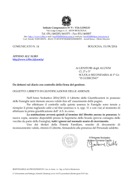
Libretto di istruzioni
OTOPLUS
Release 00
OTOPLUS
0476
Libretto di istruzioni
Instruction manual
01
Release
Ing. Francesco Marrone
Redatto
14-10-2006
Data
Longo M.
Approvato
14-10-2006
Data
2
Libretto di istruzioni
OTOPLUS
Release 01
1
2
3
4
5
6
06
07
7
8
9
10
11
12
08
09
n° matricola
01
Release
Ing. Francesco Marrone
Redatto
14-10-2006
Data
Longo M.
Approvato
14-10-2006
Data
3
Libretto di istruzioni
OTOPLUS
Release 01
Italiano
English
Queste istruzioni descrivono tutte le versioni del
riunito OTOPLUS ed il massimo degli accessori
possibili, pertanto non tutti i paragrafi potranno
trovare pratica applicazione nell’apparecchio da
Lei acquistato.
These instructions apply to all the versions of the
OTOPLUS unit and all the related accessories.
For this reason, not all the paragraphs of this
manual will refer to the equipment you have
bought.
La EUROCLINIC fornirà ai tecnici dell’assistenza
autorizzata tutte le informazioni necessarie
all’installazione e riparazione.
EUROCLINIC will provide the authorised service
center with all the information necessary to install
and repair the equipment.
E’ vietata la riproduzione, la memorizzazione e la
trasmissione in qualsiasi forma (elettronica,
meccanica, mediante fotocopia, traduzione
oppure altri mezzi) di qualunque pubblicazione
senza autorizzazione scritta della EUROCLINIC.
No part of this manual is to be reproduced, stored
in a retrieval system or transmitted in any form or
in any means, i.e. electronic, mechanical,
photocopying, translation or otherwise, without the
prior written permission of EUROCLINIC.
01
Release
Ing. Francesco Marrone
Redatto
14-10-2006
Data
Longo M.
Approvato
14-10-2006
Data
4
Libretto di istruzioni
OTOPLUS
Release 01
1. INTRODUZIONE
1. INTRODUCTION
1.1 Caratteristiche generali ed identificazione
delle parti
1.2 Avvertenze importanti
1.3 Simbologia
1.1 General characteristics and identification of
the parts
1.2 Cautions
1.3 Symbols
2. INSTALLAZIONE
2. INSTALLATION
3. USO DEGLI STRUMENTI
3. USE OF THE INSTRUMENTS
3.1
3.2
3.3
3.4
Comandi sul frontale
Insufflatore
Siringa
Aspiratore
3.4.1 Kit imbuto
3.5 Nebulizzatore medicinali
3.1 Front commands
3.2 Insufflator
3.3 Syringe
3.4 Suction
3.4.1
3.5 Medicine nebulizer
4. USO DEGLI ACCESSORI
4.1
4.2
4.3
4.4
4. USE OF THE ACCESSORIES
Presa elettrica posteriore
Vano germicida
Lampada di Clar
Scaldaspecchietti laringei
4.1
4.2
4.3
4.4
5. MANUTENZIONI
5.1
5.2
5.3
5.4
5.5
5.6
5.7
5.8
5.9
Back Socket
Germicide compartment
Clar lamp
Larynx mirror-warmer
5. MAINTENANCE
Controllo filtro anti-condensa
Rabbocco serbatoio acqua
Manutenzione Generale e Ricambi
Pulizia ordinaria recipiente secreti
Pulizia del riunito
Manutenzione vaso secreti
Svuotamento condensa
Smaltimento o rottamazione
Tabelle prodotti disinfettanti
5.1
5.2
5.3
5.4
5.5
5.6
5.7
Empty condense filter
Filling the water tank
General maintenance and spare parts
Cleaning secretions tank
Cleaning of the unit
Discharge and scrap
Disinfectant products chart
6. TECHNICAL CHARACTERISTICS
6. CARATTERISTICHE TECNICHE
6.1 Tabelle dati tecnici-potenze assorbite
6.2 Riepilogo tempi di funzionamento degli
strumenti – identificazione riunito.
7. TARGHETTE IDENTIFICATIVE
6.1 Technical data charts – absorbed power
6.2 Working periods of the instruments summary
– identification of the unit
7. IDENTIFICATION LABELS
7.1 Serial Number Label
7.2 Protection Mass Label
7.1 Targhetta matricola
7.2 Targhetta massa di protezione
8. GUIDE CHARTS AND PRODUCER’S
DECLARATIONS
8. TABELLE GUIDA E DICHIARAZIONE DEL
COSTRUTTORE
01
Release
Ing. Francesco Marrone
Redatto
14-10-2006
Data
Longo M.
Approvato
14-10-2006
Data
5
Libretto di istruzioni
OTOPLUS
Release 01
C
A
D
B
01
Release
Ing. Francesco Marrone
Redatto
14-10-2006
Data
Longo M.
Approvato
14-10-2006
Data
6
Libretto di istruzioni
OTOPLUS
Release 01
1. INTRODUZIONE
1. INTRODUCTION
1.1 Caratteristiche generali ed identificazione delle parti
1.1 General characteristic and identification of the parts
Complesso ad uso esclusivamente per il settore otorino nato
per effettuare sia operazioni di pulizia delle cavità nasali e
auricolari tramite strumenti attivi sia come ausilio e supporto
strumentario del medico otorinolaringoiatra che è l’unico
utilizzatore previsto dalla Euroclinic. Completamente autonomo
esso è mobile su ruote piroettanti auto- frenanti.
Unit for otorhinolaringology completely autonomous and
mobile on castor wheels composed of:
A)
Instrument tray holder wich is able to hold up to a
maximum of 4 instruments. It has articuled arms wich
enables one to position it in the most confortable of ways.
A) Tavoletta porta strumenti atta a sostenerne fino ad un
massimo di quattro. Dotata di bracci articolati che ne
consentono il posizionamento nella posizione ritenuta più
consona alle proprie esigenze di lavoro.
B)
Suction instruments holder
C)
Duropall working bench complete with waterproof back
panel: a back panel which houses different sockets is
available by request.
B)
C)
Mobiletto modulare contenente le apparecchiature di
aspirazione.
Piano di lavoro in materiale antigraffio Duropall completo
di alzatine salvagoccia: a richiesta è disponibile una
alzatina in grado di ospitare prese di corrente di diversi
tipi.
D) Alloggiamento per le apparecchiature ausiliarie completato
da una serie di cassetti e vani di dimensioni e
caratteristiche variabili secondo la configurazione scelta.
1.2
AVVERTENZE IMPORTANTI
1.
Non installate l’apparecchiatura in ambienti esposti al
rischio di esplosioni o esposti al gelo.
2.
La temperatura e l’umidità relativa e la pressione
dell’ambiente nel quale l’apparecchio viene installato
devono essere comprese rispettivamente tra 10°C e
40°C, tra il 30% e il 75% e tra 700 mBar a 1060 mBa r .
3)
Al momento dell’installazione deve essere verificata la
corrispondenza tra quanto indicato nella targhetta posta
sul retro dell’apparecchiatura e la tensione in uso, al fine
di evitare danneggiamenti.
4)
Il montaggio, le riparazioni, le modifiche, le tarature e
quant’altro
comporti
la
apertura
dei
cofani
dell’apparecchiatura devono essere effettuati da
personale autorizzato dalla EUROCLINIC.
5)
L’impianto elettrico dove viene installata l’apparecchiatura
deve essere conforme alle norme C.E.I. 64.4.
6)
L’apparecchiatura deve essere utilizzata esclusivamente
secondo le istruzioni riportate nel presente libretto.
7)
La EUROCLINIC declina ogni responsabilità per guasti o
incidenti dovuti a imperizia dell’utilizzatore, mancata
osservazione delle norme di sicurezza, utilizzo
dell’apparecchiatura difforme dall’uso per la quale è stata
prevista, mancata utilizzazione dell’apparecchiatura
secondo le istruzioni riportate nel presente libretto ed in
generale per tutte le cause non riconducibili a difetto di
materiale o di costruzione.
8)
D)
Housing for the auxillary instruments complete with a
series of drawers & spaces of various sizes and dimensions
according to one’s choice
1.2
CAUTIONS
1)
Do not install the machinery in environments which are
exposed to explosions or frost.
2)
The temperature and relative humidity and
environmental temperature in which the machinery is
installed should be respectively included between 10°C
and 40°C, 30% and 75%, 700 mBar and 1060 mBar.
3.
During installing, check that the electrical tension on
the sticker on the machine corresponds to that in use in
order to avoid damaging.
4)
The building, repairing, modifying, callibration and all
the other operations that require the opening of the unit
should be carried out by technical staff authorized by
EUROCLINIC.
5)
The electrical circuit in which the unit is connected to,
should comply to the IEC 64.4 regulation (regulation
regarding electrical circuits in rooms used for medical
purposes).
6)
The machinery should be used exclusively following
the instructions illustrated in this manual.
7)
EUROCLINIC refuses any responsability for the
following: damages or accidents caused by the
carelessness of the user, the non compliance to the
safety rules, a non correct use of the machine, a use of
the machine which is different to that of its purpose.
EUROCLINIC denies all responsability which has
nothing to do with faults in the material and non correct
building.
8)
Before installation and functioning check that there are
not loose parts, burnt electric cables, or various
anomalies and if they are evident please contact
EUROCLINIC
or
authorised
technical
staff.
Verificare prima d’installazione e della messa in funzione
che non ci siano parti staccate,abrasioni dei cavi elettrici,
o anomalie varie e nel caso esse siano presenti
contattare l’ Euroclinic o del personale autorizzato.
01
Release
Ing. Francesco Marrone
Redatto
14-10-2006
Data
Longo M.
Approvato
14-10-2006
Data
7
Libretto di istruzioni
OTOPLUS
Release 01
9) Gli apparecchi di Radiocomunicazione portatili e mobili
possono influenzare il funzionamento del dispositivo medico
OTOPLUS.
9) Mobile phones and radios can influence the good
functioning of medical device OTOPLUS.
10) Se durante l’utilizzo del dispositivo OTOPLUS si notano
cambiamenti di prestazioni o anomalie varie si consiglia di
sospendere l’operazione , spegnere la macchina e contattare i
tecnici autorizzati Euroclinic al fine di evitare qualsiasi tipo di
danneggiamento o deterioramento.
10) If during the use of unit OTOPLUS happen strange
changes of performance or various anomalies we
suggest to interrupt all operations, switch off the
machine and contact authorised staff EUROCLINIC in
order to avoid any kind of damage.
01
Release
Ing. Francesco Marrone
Redatto
14-10-2006
Data
Longo M.
Approvato
14-10-2006
Data
8
Libretto di istruzioni
OTOPLUS
Release 01
1.3 Simbologia
1.3 Symbols
Classificazione dell’apparecchiatura di tipo “B”
Apparecchiatura di tipo “B” (Apparecchio di classe
I, II o III, od apparecchio munito di sorgente
elettrica interna, avente un grado di protezione
contro i contatti diretti e indiretti con particolare
riguardo per:
le correnti di dispersione ammissibili
l’affidabilità del contatto di messa a
terra).
Apparecchiatura di classe I
Classification of the “B” type machinery.
“B” type machinery (machinery of the type I,II,III or
machinery housing an internal electric source with a
protection degree against direct and indirect contact
and in particular for:
- permitted current dispersion
- reliability of the ground contact)
Class I machinery.
Questo simbolo indica: PER CHIARIMENTI
CONSULTARE LA DOCUMENTAZIONE
ALLEGATA
This symbol indicates: FOR FURTHER INFORMATION
CONSULT THE ATTACHED DOCUMENTATION
Questo simbolo indica: ATTENZIONE !
CONSULTARE LA DOCUMENTAZIONE
ANNESSA
This symbol indicates: ATTENTION !!! CONSULT THE
ATTACHED DOCUMENTATION
Nel caso in cui la presa di corrente ausiliaria
venga utilizzata per alimentare apparecchiature
esterne al riunito, occorre accertarsi che le stesse
siano conformi alla normativa C.E.I. 62.5 e che
per il loro funzionamento necessitino dei seguenti
valori di corrente: 220/240 V AC 4A
If the sockets situated on the back panel are used for
feeding other instruments different to the unit, it is
advisable to check that they comply with the IEC 62,5
law and that they need the following current: 220/240 V
AC 4A
Contatto di messa a terra dell’apparecchiatura
Earthing contact of the machinery
Corrente alternata
Alternated current
Symbol discharge and scrap
Simbolo smaltimento
2. INSTALLATION
2. INSTALLAZIONE
L’installazione dell’apparecchiatura deve essere effettuata
rispettando le istruzioni del seguente libretto di istruzioni . Essa
deve essere effettuata da personale autorizzato Euroclinic o
visto la estrema semplicità delle operazioni può essere
effettuata anche dal cliente sotto propria responsabilità.
Deve, comunque, essere predisposto dall’utilizzatore
l’allacciamento elettrico che dovrà essere conforme alla
normativa C.E.I. 64.4. Le operazioni sono:
•
•
Riempire la tanica non fino all’orlo (vedi Cap 5.1)
Inserire la spina in una presa elettrica
Si consiglia di inserire la spina in una presa di corrente protetta
da un interruttore bipolare conforme alle norme C.E.I. e con le
seguenti caratteristiche tecniche:
230 V
50 A
apertura dei contatti 3 millimetri.
Per verificare che l’installazione sia stata effettuata
correttamente è sufficiente controllare che il tasto di
accensione sia illuminato (VEDI FIG. 1) e che nessun segnale
acustico sia presente.
01
Release
Ing. Francesco Marrone
Redatto
14-10-2006
Data
The installation of the equipment must be made
respecting the instructions of the following booklet of
instructions. It must be mate by authorised staff
Euroclinic, or thanks to the simplicity of operations also
by the user themselves under their responsibility.
The user should always make sure that the electric
circuit complies to IEC values (in other words: 220/240
V, alternate monophase 50 Hz, the plant should comply
with IEC 64.4 regulation). The operations are:
•
•
Full the tank but not to the rim
Insert the plug in a socket
It is advisable to insert the plug in a socket with a
bipolar switch compliant to IEC and having the following
technical characteristics:
230 V
50 A
contact opening of 3 mm.
To check that the installation has been properly made it
is enough to check that the switch on button is properly
lit up (SEE PICTURE 1) and that no acoustic signal is
present.
Longo M.
Approvato
14-10-2006
Data
Libretto di istruzioni
9
OTOPLUS
Release 01
1
2
3
Figura 1
Picture 1
01
Release
Ing. Francesco Marrone
Redatto
14-10-2006
Data
Longo M.
Approvato
14-10-2006
Data
Libretto di istruzioni
10
OTOPLUS
Release 01
3.
USO DEGLI STRUMENTI
3. USE OF THE INSTRUMENTS
Per l’uso degli strumenti a disposizione sull’apparecchiatura
occorre procedere all’accensione dell’apparecchiatura stessa
premendo l’interruttore 1 posto sul frontalino del piano di
lavoro. L’illuminarsi dello stesso con una luce verde indica che
l’apparecchiatura
è
in
funzione.
Lo
spegnimento
dell’apparecchiatura si effettua con una seconda pressione
dell’interruttore.
In order to use the instruments of the machine it is necessary
to proceed with the switch on of the machine by pressing the
button 1 on front of the work bench. When the green light is on,
this means that the machine is working. Turn it off by pressing
the same switch again.
3.1 Frontal comands
3.1 Comandi sulla tavoletta
Di seguito sono elencati i comandi presenti sulla tavoletta
porta strumenti del riunito: il loro uso è possibile solo dopo
aver acceso l’interruttore generale (vedi figura 1). Quindi:
1-
Interruttore generale
2-
Interruttore inserimento e spegnimento ciclo acqua
calda
3-
Potenziometro per la lampada di Clar.
Ruotandolo in senso orario aumenta la luce, in
senso opposto la luce diminuisce.
The following comands are present on the instruments board
of the unit: it is possible to use them only after turning the
general switch on (see picture 1)
1-
general switch
2-
water heating switch
3-
potentiometer for Clar lamp.
By turning it clockwise the light increases by turning
it the opposite way it decreases
3.2 Insufflator
3.2 Insufflatore
Per un funzionamento ottimale dello strumento si consiglia di
seguire i seguenti tempi di utilizzo:
Lavoro 5’
Riposo 10’’
For a correct use of the instrument it is advisable to work
according to the following periods:
work 5 min
pause 10 sec
Il funzionamento dello strumento si ottiene estraendolo dalla
propria sede e spingendo il pedale ON-OFF. L’accensione
della luce led corrispondente sulla tavoletta indica che lo
strumento è in funzione.
Per variare l’intensità di soffiaggio occorre agire sulla levetta
posta sul terminale porta cannula.
N.B. Usare esclusivamente ricambi Euroclinic.
The functioning of the instrument stars when it is taken out of
its housing and pushing the pedal.
When the corresponding light on the instrument holder is on,
this means that the instrument is working.
In order to vary the intensity of air, one should adjust it with the
lever behind the cannula holder.
3.3 Siringa lavaggi auricolari
Per un funzionamento ottimale dello strumento si consiglia di
seguire i seguenti tempi di utilizzo:
Lavoro 5’
Riposo 10’’
Prima di utilizzare la siringa bisogna assicurarsi che la tanica
sia riempita ma non fino all’orlo.
Il funzionamento dello strumento si ottiene estraendolo dalla
propria sede. L’accensione della luce corrispondente sulla
tavoletta indica che lo strumento è in funzione.
Per ottenere il flusso di acqua calda per prima cosa è
necessario premere l’interruttore dell’acqua calda posto sulla
tavoletta del riunito (vedi capitolo 3.1) a seguito del quale
comincia a lampeggiare il led stand-by sulla tavoletta. A
temperatura raggiunta il led si accende e si attiva un segnale
sonoro. A questo punto si può premere uno qualunque dei due
pulsanti posti nell’impugnatura della siringa.
N.B. Usare esclusivamente ricambi Euroclinic.
N.B. Il primo ciclo di riscaldamento dura all’incirca 10
minuti
N.B. Al primo ciclo di riscaldamento oppure dopo una pausa
prolungata con macchina spenta ,a temperatura raggiunta e’
sempre necessario far uscire dalla siringa un getto d’acqua per
10 secondi in modo da assestare la macchina.
01
Release
Ing. Francesco Marrone
Redatto
14-10-2006
Data
3.3 Ear washings syringe
For a correct functioning of the instrument we
suggest to use it according to the following periods:
Work 5 min
Off
10 sec
Before using the syringe it is necessary to fill up, not
completely full, the tank.
The functioning of the instrument is activated by taking it out of
its housing. When the corresponding indicator-light on the
instruments tablet is lit up, this means that the instrument is
functioning.
For obtaining warm water flux, firstly turn on the warm water
switch placed in the front of the unit (see section 3.1): the led
stand-by on the tablet starts blinking. When the right
temperature is reached, the led is lit up and the acoustic sign is
activated. Now it is possible to push one of the two buttons
placed in the syringe hand-piece.
N.B. Use only spare parts by EUROCLINIC.
N.B. The First cycle of heating lasts approximately 15
minutes
N.B. During the first heating cycle or after a prolonged pause
with the unit off, as soon as the right temperature is reached, it
is always necessary to make overflow from the syringe a water
jet for 10 second, in order to settle the unit.
Longo M.
Approvato
14-10-2006
Data
11
Libretto di istruzioni
OTOPLUS
Release 01
N.B. Nella evenienza in cui la temperatura dell’acqua superi il
valore prestabilito un termostato di sicurezza blocca
automaticamente il funzionamento della siringa lavaggi e si
attiva un segnale acustico fisso di avviso, fino a che non viene
ripristinato il normale ciclo.
ATTENZIONE!! In caso di riserva spegnere subito la
macchina e rabboccare la tanica.
N.B. In case that the water temperature overcome the set
value, a safety thermostat blocks automatically the ear
washing syringe and a fix acoustic advising signal is activated,
until the normal cycle is not re-activated.
WARNING!! In case of reserve please immediately switch off
the equipment and fill up the tank.
Insufflatore / insufflator
Siringa / syringe
Nebulizzatore medicinali /
Medicaments atomizer
Aspiratore / suction
Fig. 2
Pic.2
01
Release
Ing. Francesco Marrone
Redatto
14-10-2006
Data
Longo M.
Approvato
14-10-2006
Data
12
Libretto di istruzioni
OTOPLUS
Release 01
3.4 Aspiratore (Vedi Fig 2)
3.4 Suction (See Pic. 2)
Per un funzionamento ottimale dello strumento si
consiglia di seguire i seguenti tempi di utilizzo:
Lavoro 5’
Riposo 10’’
ll funzionamento dello strumento si ottiene estraendolo dalla
propria sede. L’accensione della luce corrispondente sulla
tavoletta indica che lo strumento è in funzione.
Per variare l’intensità di aspirazione agire sulla levetta posta
sul terminale porta cannule. (vedi figura precedente).
N.B. Usare esclusivamente ricambi Euroclinic.
3.4.1. Accessori x Aspiratore
Il riunito Otoplus viene predisposto con un beccuccio estraibile
con in testa un pezzo di tubo siliconico (vedi Fig 3.4.1) ; inoltre
a corredo con la macchina viene fornito un Kit per poter
installare l’imbuto raccogli
secreti (vedi Fig 3.4.2); il Kit
contiene un raccordo innestabile al tubo dell’aspirazione più
l’imbuto vedi fase di montaggio.
For a correct use of the instrument it is advisable to work
according to the following periods:
Work 5 min
Off 10 sec
The starting of the instrument is obtained by taking it out of its
housing. When the corresponding light on the tray is on this
means that the instrument is working. To vary the intensity of
the aspiration it is necessary to adjust the lever placed on the
end of the cannula holder. (see previous picture)
NB: Use only spare parts by EUROCLINIC.
3.4.1. Accessori x Aspiratore
The unit Otoplus is set with a pulling-out neck headed by a
piece of silicone pipe (see pic. 3.4.1) ); moreover together with
the machine is supplied an apposite Kit for setting the funnel
for secretions collecting (see pic. 3.4.2) – which contains a
pipe fitting to be coupled to the suction pipe + funnel (see
assembling phase).
Antimicrobial hydrophobic filter
Fig 3.4.1
Pic. 3.4.1
On the Unit is planned an antimicrobial hydrophobic filter on
suction (see pic. 3.4.2), in order to ensure the killing (99%) of
any bacteria that come from the suction system. The
replacement is advisable every 10 – 15 working days.
Filtro Idrofobico Anticontaminazione
3.5 Medicaments Atomizer (See Pic. 2)
Filtro Antibatterico
Antimicrobial Filter
Fig 3.4.2
Pic. 3.4.2
Sul riunito è previsto un filtro antibatterico idrofobico
sull’aspirazione (vedi fig. 3.4.2) in grado di garantire
l’abbattimento al 99% degli eventuali batteri provenienti dal
circuito di aspirazione. Si consiglia la sostituzione, in base
all’utilizzo dell’aspirazione, ogni 10-15 giorni lavorativi.
For a correct use of the instrument it is advisable to work
according to the following periods:
Work 5 min
Off 10 sec
The functioning of the instrument is obtained by taking it out of
its housing and pushing the pedal. When the corresponding
light on the tray is on this means that the instrument is working.
In order to obtain the nebulization of the medicine products it is
necessary to adjust the handpiece of the instrument. (see
previous picture).
N.B. Use only spare parts EUROCLINIC.
3.5 Nebulizzatore medicinali (Vedi Fig. 2)
Per un funzionamento ottimale dello strumento si consiglia di
seguire i seguenti tempi di utilizzo:
Lavoro 5’
Riposo 10’’
ll funzionamento dello strumento si ottiene estraendolo dalla
propria sede e spingendo il pedale ON-OFF. L’accensione
della luce corrispondente sulla tavoletta indica che lo
strumento è in funzione.
Per ottenere la nebulizzazione dei prodotti medicinali agire
sulla leva dell’impugnatura dello strumento. (vedi fig.
precedente).
N.B. Usare esclusivamente ricambi Euroclinic.
01
Release
Ing. Francesco Marrone
Redatto
14-10-2006
Data
Longo M.
Approvato
14-10-2006
Data
13
Libretto di istruzioni
OTOPLUS
Release 01
GANCIO PER SUPPORTO
E ACCENSIONE
SUPPORT HOOK
AND LIT UP
SUPPORTO OTTICHE
Fixed Holder for endoscope
LAMPADA DI CLAR/
CLAR LAMP
VANO GERMICIDA/
GERMICIDE COMPARTMENTS
INTERRUTTORE
ACCENSIONE
SWITCH ON
BUTTON
INTERRUTTORE
ACCENSIONE SCALDA SPECCHIETTI
Fig. 3
Pic. 3
01
Release
Ing. Francesco Marrone
Redatto
SWITCH ON BUTTON MIRROR
WARMER
14-10-2006
Data
Longo M.
Approvato
14-10-2006
Data
14
Libretto di istruzioni
OTOPLUS
Release 01
4. USO DEGLI ACCESSORI
4. USE OF THE ACCESSORIES
4.1 Socket back panel
4.1 Presa elettrica
Al momento dell’installazione dell’apparecchio, la presa di
corrente viene collegata automaticamente alla rete elettrica.
Controllare quindi che eventuali apparecchi o utensili collegati
alla presa supplementare possano funzionare alla tensione
rispondente alla normativa C.E.I. 64.4, cioè 220/240 V
alternata monofase 50 Hz.
La presa e’ protetta da fusibile di 4A per cui con carichi
oltre i 900 VA esso interviene.
Staccare sempre questi apparecchi accessori dopo l’uso o al
momento della pulizia,manutenzione del riunito; non collegare
mai più di un apparecchio alla presa.
When installing the machine, the plugs are automatically
connected to the electric system.
Check that other instruments connected to supplementary
sockets can function with 220-240 V alternated monophase
Hz.
Always take the plugs of these other instruments out after their
use and during cleaning: do not connect more then one
instrument to each socket.
4.2 Germicide compartments (See Pic.3)
4.2 Vano germicida (Vedi Fig. 3)
A scelta, il dispositivo può essere equipaggiato da questo
cassetto ausiliario che consente solamente il mantenimento in
condizioni igieniche dello strumentario già sterilizzato.
Il funzionamento della lampada a raggi U.V. si predispone
accendendo l’interruttore generale del riunito (vedi cap.3).
La lampada germicida si accende e si spegne mediante
l’interruttore posto sul lato della cassettiera (vedi fig. 3) Un
interruttore di sicurezza spegne automaticamente la lampada
in caso di apertura accidentale del vano germicida, e la
riaccende al momento della chiusura dello stesso.
ATTENZIONE! Si intende ribadire ulteriormente che il vano
germicida non costituisce elemento di sostituzione del
processo di sterilizzazione ma solo da coadiuvante e da
supporto.
N.B. Non usare lampade con caratteristiche tecniche diverse
da quelle imposte dalla Euroclinic.
N.B. Si consiglia di sostituire la lampada ogni 500h circa
di funzionamento.
ATTENZIONE! Scollegare la spina di alimentazione del riunito
prima di effettuare qualsiasi intervento sull’impianto UV
4.3 Lampada di Clar (Fig. 3)
L’accensione della lampada avviene automaticamente
sollevandola dal suo aggancio, così come il suo spegnimento
si ottiene riponendola: la regolazione dell’intensità della luce si
ottiene agendo sul potenziometro posto sulla tavoletta (vedi
cap. 3.1)
On request, the machine can be equipped with this auxiliary
drawer, that permits only the maintenance in hygienically
conditions of the instruments already sterilized.
The functioning of the UV lamp is obtained by turning the
general switch of the unit on (see chapter 3).
The germicide lamp can be turned on and off by a switch
placed on the side of the drawers turns the lamp off
automaticaly if the germicide compartment is accidentally
opened, and it will turn the lamp on again when the drawer is
closed.
WARNING! We repeat once more that the germicidal space
does not constitute substitutive element of the sterilization
process, but function only as co-adjuvant and supporter.
NB: do not use lamps with technical features different from
those indicated by EUROCLINIC.
N.B. We suggest to substitute the lamp each 500 hours of
functioning
4.3 Clar Lamp (Pic. 3)
The lamp is turned on automatically by taking it from its
housing, to turn it off it is necessary to place it back.
The adjusting of the intensity of the light is obtained by
adjusting the potentiometer placed on the instruments board
(see chapter 3.1)
4.4 Mirror-warned larinx
4.4 Scalda specchietti (Fig.3)
Il funzionamento dello scalda specchietti si ottiene premendo
l’interruttore posto sotto lo stesso (vedi Fig. 3). Il getto di aria
calda è temporizzato ( circa 20 Sec).
ATTENZIONE!!!
WARNING !
N.B. Se troppo usato il sistema possiede un interruttore
termico di sicurezza che blocca il flusso di aria fino a che
non si torna a valori normali di temperatura ; e’ necessario
quindi aspettare qualche minuto prima di riutilizzarlo.
01
Release
Ing. Francesco Marrone
Redatto
The functioning of the mirror-warned larynx is obtained by
pressing the switch placed next to the fan (see figure).
Place the surgical instrument in front of the warm air flux and
wait a few seconds.
14-10-2006
Data
N.B. When overused, the system has a thermal safety
switch which stops the air flow until normal values of
temperature are reached again; it is necessary in that case
to wait for some minutes before using it again.
Longo M.
Approvato
14-10-2006
Data
15
Libretto di istruzioni
OTOPLUS
Release 01
5.
MANUTENZIONE
5. MAINTENANCE
Attenzione! Tutte le operazioni sotto riportate devono essere
effettuate con apparecchiatura priva di tensione
5.1 Controllo filtro anticondensa
Vicino l’anta è presente un filtro per la raccolta della condensa
creata dal compressore; nel caso esso si riempia è necessario
svuotarlo; posizionare un bicchiere sotto al filtro girare e tirare
verso il basso il pomolo, svuotare la condensa e richiudere il
pomolo!
Attenzione!! Se il pomolo non viene chiuso il compressore
sfiata l’aria attraverso di esso!
5.2 Rabbocco serbatoio acqua
In caso di segnale acustico intermittente vuol dire che e’
intervenuta la riserva del serbatoio dell’acqua per la siringa
occorre procedere al rabbocco del serbatoio stesso. Per
questa operazione occorre procedere nella maniera di seguito
specificata:
1_
2_
3_
4_
5_
Togliere la tensione all’apparecchiatura;
aprire lo sportello del vano alloggiamento delle
apparecchiature ausiliarie;
estrarre il contenitore, svitare il tappo ed immettere acqua
nel recipiente senza raggiungere il livello max;
richiudere recipiente e sportello;
ridare tensione all’apparecchio.
Attention! The following proceeding have to be carried out
when the machine isn’t plugged into the mains.
5.1 Empty of the condense filter
Near the panel there is a filter for collecting the condense
created by the compressor; in case it is filled it is necessary to
empty it; place a glass under the filter, turn the knob and pull
downside the knob, empty the condense and close again the
knob!
Warning! If the knob is not closed the compressor leaks air
through it!
5.2 Filling the water tank
In acoustic case of signal intermittent it means that it is
intervened the reserve of the tank and that it is necessary to fill
it up. In order to fill the tan please proceed in the following way:
1234-
5-
take the plug out of the machine
open the door of the auxillary instruments
compartment
take the tank out, unwind the tap and with a funnel
pour the water,without reach the maximum level .
close the tap and the door
plug the machine in again
Notice: We suggest you to use only distilled water
N.B. Si consiglia di utilizzare solo H20 distillata
Vano alloggiamento
Auxiliary instruments
compartment
01
Release
Ing. Francesco Marrone
Redatto
14-10-2006
Data
Longo M.
Approvato
14-10-2006
Data
16
Libretto di istruzioni
OTOPLUS
Release 01
Aprire lo
sportello
Open the door
Svitare il tappo
Unwind the tap
Immettere acqua nel
recipiente (no max)
Introduce distilled water
in the tank (no max)
01
Release
Ing. Francesco Marrone
Redatto
14-10-2006
Data
Longo M.
Approvato
14-10-2006
Data
17
Libretto di istruzioni
OTOPLUS
Release 01
5.3 Manutenzione Generale e Ricambi
Per garantire il corretto funzionamento del dispositivo la
Euroclinic consiglia di procedere ad una revisione periodica
biennale dell’intero dispositivo.
La EUROCLINIC declina ogni responsabilità per guasti,
incidenti o inefficienze dovuti alla sostituzione di ricambi non
originali.
5.3 General maintenance and spare parts
To grant the correct functioning of the machinery
EUROCLINIC suggest to proceed with a complete revision of
the unit each 2 years.
EUROCLINIC declines any responsibility for damages, hitches
or inefficiencies due to the substitution of NON ORIGINAL
spare parts.
5.4 Pulizia ordinaria recipiente secreti
5.4 Cleaning of the secretion tank
Giornalmente alla fine del lavoro procedere alla pulizia del
recipiente dove si raccolgono i secreti. Per effettuare questa
operazione procedere nel seguente modo (Vedi Fig. 4):
At the end of a days work it is necessary to clean the tank
where all the secretions gather. In order to carry out this
operation, proceed in the following way:
1_
2_
3_
123-
4_
5_
Togliere la tensione al riunito;
aprire il vano alloggiamento del recipiente;
svitare il recipiente ruotandolo in senso antiorario per
estrarlo dal coperchio, che è fisso;
svuotare il recipiente, e pulirlo a fondo
riavvitare il recipiente al coperchio, richiudere e ridare
tensione al riunito.
45-
unplug the unit
open the door where the tank is housed
unwind the tank by turning it anticlockwise to separate it
from the tap which is fixed
empty the tank and clean it thoroughly
re-attach the tank to the tap close the door and plug the
unit it again
5.5 Pulizia del riunito
5.5 Cleaning the unit
La scelta e l’applicazione dei materiali impiegati nella
costruzione è stata effettuata per rispondere a precise
esigenze di pulizia e disinfezione cui tali materiali andranno ad
essere sottoposti.
Data la grande diversità di prodotti chimici utilizzati in uno
studio medico, può accadere che le superfici, laccate smaltate
o in acciaio inox vengano danneggiate. Dato che i danni alle
superfici dipendono in gran parte dal tempo di permanenza di
questi prodotti sulle superfici stesse, è importante asciugare
immediatamente le parti interessate con un panno umido. Per
la normale pulizia delle parti verniciate o in acciaio inox, usare
un prodotto specifico adatto per questi materiali che ne
permetta la pulizia senza intaccare la loro composizione.
IMPORTANTE: non usare prodotti contenenti alcool,
ammoniaca, sostanze abrasive o benzolo.
The choice of materials used for building the unit has been
carefully taken in order to correspond to the cleaning and
disinfecting needs.
Given the big differences between chemical products used in a
medical study, it is possible to ruin the tops. The major
damages are caused by the amount of time that these
chemical products are left on the tops. It is important to
immediatly dry the interested parts with a damp cloth.
To clean the painted or metal parts, use a specific product for
these materials which doesn’t damage their composition.
IMPORTANT! Do not use products with alcohol, amonia or
petrol
5.6 Pulizia e manutenzione dei vasi di raccolta secreti
5.6 Cleaning and maintenance of secretion tank
I vasi di raccolta per liquidi aspirati possono essere puliti con
acqua e detergenti compatibili con i materiali impiegati (vedi
tabella allegata) e/o sterilizzati in autoclave a 135°C. Separare
le parti fondamentali dei vasi di raccolta prima della
sterilizzazione, inserire il bicchiere con il fondo verso l’alto in
autoclave e non sovrapporre pesi durante la permanenza in
disinfezione.
The tank which contains the aspirated liquids can be cleaned
with water and detergents which are compatible with the
materials (see chart) used and/or sterilized in an autoclave
at 135° C. Separate the main parts of the tank befo re the
sterilization, insert the glass upside down in the autoclave
and do not place anything on top of it whilst disinfecting.
NON USARE SOLVENTI OD ALCOOL PER LA PULIZIA E LA
DISINFEZIONE: L’IMPIEGO DI QUESTI PRODOTTI PUO’
DANNEGGIARE LE COMPONENTI IN MATERIALE
PLASTICO DEI SISTEMI.
Sostituire sempre le parti danneggiate o difettose con ricambi
originali Euroclinic
In caso di pulizia in autoclave attenersi categoricamente alla
tabella temporale presente nella Sezione 5.6
01
Release
Ing. Francesco Marrone
Redatto
14-10-2006
Data
DO NOT USE SOLVENTS OR ALCOHOL FOR CLEANING
AND DISINFECTING. THE USE OF THESE PRODUCTS CAN
DAMAGE THE PLASTIC PIECES OF THE SYSTEM.
Always substitute the damaged or faulty parts with original
spare parts.
In case of cleaning in autoclave strictly respect the timing chart
explained in section 5.6.
Longo M.
Approvato
14-10-2006
Data
18
Libretto di istruzioni
OTOPLUS
Release 01
5.7 Svuotamento condensa
Vicino l’anta è presente un filtro per la raccolta della condensa
creata dal compressore; nel caso esso si riempia è necessario
svuotarlo; posizionare un bicchiere sotto al filtro girare e tirare
verso il basso il pomolo,svuotare la condensa e richiudere il
pomolo!
Attenzione! Se il pomolo non viene chiuso il compressore
sfiata l’aria attraverso di esso
5.8 Smaltimento o Rottamazione
Il dispositivo non contiene elementi nocivi o pericolosi e può
quindi seguire le normali procedure di rottamazione e
smaltimento secondo le direttive vigenti del paese in cui il
riunito ha lavorato.
5.7 Svuotamento condensa
Vicino l’anta è presente un filtro per la raccolta della condensa
creata dal compressore; nel caso esso si riempia è necessario
svuotarlo; posizionare un bicchiere sotto al filtro girare e tirare
verso il basso il pomolo,svuotare la condensa e richiudere il
pomolo!
Attenzione! Se il pomolo non viene chiuso il compressore
sfiata l’aria attraverso di esso
5.8 Discharge and scrap
The unit does not contain dangerous or toxic elements and
can therefore follow normal discharging and scraping
procedures in law in the Country where it has worked.
Aprire lo
sportello
Open the panel
Svitare
ruotando
in senso
antiorario
to unscrew
rotating in
sense anticlockwise
Estrarre il
recipiente e
pulirlo a fondo
Empty and clean
Fig. 4
Pic. 4
01
Release
Ing. Francesco Marrone
Redatto
14-10-2006
Data
Longo M.
Approvato
14-10-2006
Data
19
Libretto di istruzioni
OTOPLUS
Release 01
5.8 Tabella prodotti per pulizia e disinfezione
Tabella sterilizzazione strumentario
STRUMENTO
TEMP
TIPO DI STERILIZZAZIONE
Impugnatura siringa
135° C
In autoclave 5 – 7 min
Terminale nebulizzatore
135° C
In autoclave 5 – 7 min
Cannula insufflatore
135° C
In autoclave 5 – 7 min
Cannula aspiratore
135° C
In autoclave 5 – 7 min
Tabella prodotti per pulizia e disinfezione
Disinfettanti
Prodotti farmaceutici e cosmetici
+ bactol 5%
+ clorammina
- DDT
+ delegol 5%
= dimammina 5%
= tintura di iodio
- acido fenico
+ lisoformio 2%
- TB lisoformio
+ bactol
+ merfen 2%
+ octozono
+ perydrol
+ resorcina 1%
= sagrotane 5%
+ alcool da bruciare puro
+ cloruro di mercurio
+ trosilina G
+ acqua ossigenata
= zefirol
+ plasma sanguigno
+ latte solare
+ hydroplex
= tintura di iodio
+ lanolina
= mantolo 90% in alcool
- smalto per unghie
- solvente
+ sciacquo per bocca
+ periston R
+ vaselina
+ vicks vaporub
LEGENDA
+ compatibile
- non compatibile
= compatibile con riserva
01
Release
Ing. Francesco Marrone
Redatto
14-10-2006
Data
Longo M.
Approvato
14-10-2006
Data
20
Libretto di istruzioni
OTOPLUS
Release 01
5.8 Instrument strerilization chart
Instrument sterilization chart
INSTRUMENT
TEMP
KIND OF STERILIZATION
Syringe handpiece
135° C
In autoclave 5 – 7 min
Nebulizer terminal
135° C
In autoclave 5 – 7 min
Insufflator cannula
135° C
In autoclave 5 – 7 min
Aspirator cannula
135° C
In autoclave 5 – 7 min
Cleaning and disinfecting products chart
Disinfectants
Pharmaceutic products and
cosmetics
+ blood plasma
+ sun tan lotion
+ hydroplex
= iodine dye
+ lanolyn
= mantolo 90% in alcohol
-nail varnish
- solvent
+ mouth wash
+ periston R
+ vaselyn
+ vicks rub
+ bactol 5%
+ clorammina
- DDT
+ delegol 5%
= dimammina 5%
= iodine dye
- fenic acid
+ lysoform 2%
- TB lysoform
+ bactol
+ merfen 2%
+ octozone
+ perydrol
+ resorcina 1%
= sagrotane 5%
+ alcohol to be purely burnt
+ mercury chloride
+ trosilina G
+ oxiginated water
= zefirol
CHART SIGNS
+ compatible
- non compatible
= compatible but with caution
01
Release
Ing. Francesco Marrone
Redatto
14-10-2006
Data
Longo M.
Approvato
14-10-2006
Data
21
Libretto di istruzioni
OTOPLUS
Release 01
6. CARATTERISTICHE TECNICHE
6.1 Tabella dati tecnici
Tensione di alimentazione
Frequenza
Potenza assorbita (secondo la configurazione)
Peso Max
Numero massimo di strumenti
Massima pressione dell’aria
Portata aria
Max pressione acqua
Portata acqua
Dimensioni (in mm)
Altezza piano lavoro
Larghezza
Profondità
220/240 V
50 Hz
1200 VA
80 Kg
4 pz
2.2 Atm
26 l/m
2.2 Atm
0.4 l/m
850 mm
850 mm
540 mm
Tabella potenze assorbite
DESCRIZIONE
ASSORBIMENTO
TENSIONE
SERVIZIO
Lampada germicida
8W
230 V ac
Continuo
Aspiratore
70 W
230 V ac
Continuo
Compressore
70 W
230 V ac
Continuo
Pompa
48 W
230 V ac
Continuo
6.2 Riepilogo tempi di funzionamento degli strumenti
STRUMENTO
LAVORO
RIPOSO
Siringa
5‘
10”
Insufflatore
5‘
10”
Aspiratore
5‘
10”
Nebulizzatore
5‘
10”
Riepilogo identificazione apparecchiatura
1 2 3
4
5
6
05 06
7 8 9 10 11 12
07 08
n° matricola
01
Release
Ing. Francesco Marrone
Redatto
14-10-2006
Data
Longo M.
Approvato
14-10-2006
Data
22
Libretto di istruzioni
OTOPLUS
Release 01
6. TECHNICAL FEAUTURES
6.1 Technical data chart
Electrical tension
Frequency
Power absorbed by the unit (according to the configuration)
Weight Max
Maximum number of instruments
Maximum air pressure
Air capacity
Maximum water pressure
Water capacity
Dimensions (in mm)
Height of the working bench
Width
Depth
220/240 V
50 Hz
1200 VA
80 Kg
4 pcs
2.2 Atm
26 l/m
2.2 Atm
0.4 l/m
850 mm
850 mm
540 mm
Absorbed power chart
DESCRIPT.
ABSORB.
TENSION
SERVICE
Germicide Lamp
8W
230 V ac
Continuos
Aspirator
70 W
230 V ac
Continuos
Compressor
70 W
230 V ac
Continuos
Pump
48 W
230 V ac
Continuos
6.2 Summary of the working periods of the instruments
Device identification summary
INSTRUMENT
WORK
OFF
Syringe
5‘
10”
Insufflator
5‘
10”
Aspirator
5‘
10”
Nebulizer
5‘
10”
1 2 3
4
5
6
02 03
7 8 9 10 11 12
04 05
Caratteristiche principali –
Most important feautures:
n° matricola
01
Release
Ing. Francesco Marrone
Redatto
14-10-2006
Data
Longo M.
Approvato
14-10-2006
Data
23
Libretto di istruzioni
OTOPLUS
Release 01
Tensione di alimentazione
Electrical tension
Potenza Nominale
Power absorbed by the unit
Cavo di alimentazione
Electrical cable
Fusibili di protezione (uno per fase)
Fuse
Serbatoio H2O
Reservoir H2O
Dimensioni
Dimensions
230 V ac 50/60 Hz
1200 VA
3 x 1,5 mm lunghezza - Lenght: 1400 mm
250 V 6,3A
5l
Altezza - Height: 850 mm
Profondità - Depth: 540 mm
Larghezza - Width: 850 mm
80 kg
1
Peso
Weight
CARATTERISTICHE DI USCITA OTOPLUS – OTOPLUS OUT FEAUTURES
siringa con tempertaura fissa a 37°C
37° fix temperature Syringe
Portata - Capacity 0,4 L/m
TOP Antigraffio in Duropall
Duropall working plane
insufflatore (optional)
Insufflator (optional)
Aspiratore di base
Basic Suction
Capacità del vaso aspiratore
Suction reservoir capacity
Predisposizione per lampada di Clar (optional)
Clar Lamp Provision (optional)
Cassetto con impianto U.V. (optional)
UV Drawer (optional)
Scaldaspecchietti temporizzato(optional)
Mirror-warmed larynx
850x540 mm
Portata max – Maximum Capacity : 26 L/m
Vuoto Massimo - Maximum Empty: 650 mm Hg
Flusso – Flow: 25 lpm
1 litro / 1 litre
Tensione d’uscita regolabile - Out Adjustable tension : 36 VDC
1
Il peso si riferisce alla macchina con tutti i serbatoi scarichi
Weight refers to the unit with all empty reservoirs
01
Release
Ing. Francesco Marrone
Redatto
14-10-2006
Data
Longo M.
Approvato
14-10-2006
Data
24
Libretto di istruzioni
OTOPLUS
Release 01
7. TARGHETTA IDENTIFICATIVE
7.1 TARGHETTA MATRICOLA
La targhetta matricola si trova nella parte posteriore del riunito, i dati riportati sono:
The label of the serial number is located in the back part of the unit, and the details are:
•
•
•
•
•
•
Tipo di riunito – UNIT MODEL
Tensione nominale – NOMINAL TENSION
Frequenza nominale – NOMINAL FREQUENCE
Potenza massima assorbita – MAXIMUM POWER ABSORBED
Numero di serie – SERIAL NUMBER
Anno e mese di fabbricazione – YEAR AND MONTH OF FABRICATION
7.2 IDENTIFICAZIONE MASSA
All’interno della macchina la massa di protezione è indicata con il seguente simbolo adesivo :
Inside the machine the protection mass is indicated with following sticking label:
01
Release
Ing. Francesco Marrone
Redatto
14-10-2006
Data
Longo M.
Approvato
14-10-2006
Data
25
Libretto di istruzioni
OTOPLUS
Release 01
8. TABELLE GUIDA E DICHIARAZIONE DEL COSTRUTTORE
8.1 TABELLA 201 EMISSIONI ELETTROMAGNETICHE
Guida e dichiarazione del costruttore- Emissioni Elettromagnetica
Guidance and manufacturer’s declaration-electromagnetic immunity
L’OTOPLUS è previsto per funzionare nell’ambiente elettromagnetico sotto specificato.Il cliente o l’utilizzatore dell’
OTOPLUS dovrebbe assicurarsi che esso venga usato in tale ambiente
The OTOPLUS is intended for use in the electromagnetic environment specified below. The costumer or the user of the
OTOPLUS should assure that it is used in such an environment
Prova emissioni
Emissions test
Conformità
Compliance
Ambiente Elettromagnetico-Guida
Electromagnetic environment -Guidance
Emissione RF
RF Emissions
CISPR 11
Gruppo 1
Group 1
L’Otoplus utilizza energia RF solo per il suo
funzionamento interno.Perciò le sue emissioni RF sono
molte basse e verosimilmente non causano nessuna
interferenza negli apparecchi elettronici vicini.
The Otoplus uses RF energy only for its internal
function. Therefore, its RF emissions are very low and
are not likely to cause any interference in nearby
electronic equipment .
Emissione RF
RF Emissions
CISPR 11
CLASSE B
CLASS B
L’ Otoplus è adatto per tutti gli edifici,compresi gli
edifici domestici, e quelli direttamente collegati alla
rete di alimentazione pubblica in bassa tensione che
alimenta edifici per usi domestici.
L’ Otoplus is suitable for use in all establishment,
including domestic establishment and those directly
connected to the public low-voltage power supply
network that supplies buildings used for domestic
purposes
Emissioni armoniche
Harmonic emission
IEC 61000-3-2
CLASSE A
CLASS A
Emissioni di fluttuazioni
di tensione/flicker
Voltage fluctuations/flicker
emissions
Conforme
Complies
IEC 61000-3-2
01
Release
Ing. Francesco Marrone
Redatto
14-10-2006
Data
Longo M.
Approvato
14-10-2006
Data
26
Libretto di istruzioni
OTOPLUS
Release 01
8.2 TABELLA 202 IMMUNITA’ ELETTROMAGNETICA
Guida e dichiarazione del costruttore-immunità elettromagnetica
Guidance and manufacturer’s declaration-electromagnetic immunity
Il riunito otorinolaringoiatrico OTOPLUS è previsto per funzionare nell’ambiente elettromagnetico sotto specificato.
Il cliente o l’utilizzatore del riunito OTOPLUS dovrebbe assicurarsi che esso viene utilizzato in tale ambiente.
The OTOPLUS is intended for use in the electromagnetic environment specifed below. The costumer or the user of the OTOPLUS
should assure that it is used in such an environment
Prova immunità
Immunity test
Livello di prova
IEC 60601
IEC 60601
test level
Scariche elettrostatiche
(ESD)
Electrostatic discharge
(ESD)
Livello Conformità
Compliance level
Ambiente elettromagnetico-guida
Electromagnetic environment- guidance
±6 kV a contatto_ contact
±8 kV in aria_air
±6 kV a contatto_ contact
±8 kV in aria_air
±2 kV per linee di
alimentazione di potenza
±2 kV for power supply
lines
±1kV per linee di
ingreso/uscita
±1kV for input/output lines
±1 kV in modo differenziale
±1 kV differential mode
±2 kV per linee di
alimentazione di potenza
±2 kV for power supply
lines
±1kV per linee di
ingreso/uscita
±1kV for input/output lines
±1 kV in modo differenziale
±1 kV differential mode
I pavimenti devono essere in legno,
calcestruzzo o in ceramica. Se i pavimenti sono
ricoperti di materiale sintetico, l’umidità relativa
dovrebbe essere almeno del 30%.
Floors should be wood ,concrete or ceramic tile. If
floors are covered with sintetic material the relative
humidity should be at least 30%
La qualità della tensione dovrebbe essere quella di
un tipico ambiente commerciale o ospedaliero.
±2 kV in modo comune
±2 kV common mode
±2 kV in modo comune
±2 kV common mode
Mains power quality should be that of a tipical
commercial or hospital environment
<5% UT
(> 95% buco di_dip in UT)
for_per 0,5 cicli_cycle
<5% UT
(> 95% buco di_dip in UT)
for_per 0,5 cicli_cycle
40% UT
(60% buco di_dip in UT)
for_per 0,5 cicli_cycle
40% UT
(60% buco di_dip in UT)
for_per 0,5 cicli_cycle
La qualità della tensione dovrebbe essere quella di
un tipico ambiente commerciale o ospedaliero.Se
l’utilizzatore del riunito otorino Otoplus richiede un
funzionamento
continuo
anche
durante
l’interruzione della tensione di rete , si raccomanda
di alimentarlo con un gruppo di continuità (UPS) o
con batterie.
70% UT
(30% buco di_dip in UT)
for_per 0,5 cicli_cycle
70% UT
(30% buco di_dip in UT)
for_per 0,5 cicli_cycle
<5% UT
(> 95% buco di_dip in UT)
for _per 5 s
<5% UT
(> 95% buco di_dip in UT)
for _per 5 s
IEC 61000-4-2
Transitori/treni elettrici veloci
Electric fast transient/burst
IEC 61000-4-4
Impulsi
Surge
IEC 61000-4-5
Buchi di tensione, brevi
interruzioni e variazioni di
tensione sulle linee di ingresso di
alimentazione
Voltage dips,short interruptions
and voltage variations on power
supply input lines
IEC 61000-4-11
Campo magnetico alla frequenza
di rete
(50/60 Hz)
3A/m
3A/m
Power Frequency
(50/60 Hz) magnetic field
IEC 61000-4-8
Mains power quality should be that of a tipical
commercial or hospital environment
La qualità della tensione dovrebbe essere quella di
un tipico ambiente commerciale o ospedaliero.
Mains power quality should be that of a tipical
commercial or hospital environment.If the user of
the Otoplus requires continued operations during
power mainsinterruptions,it is recommended that
the Otoplus powered from an uninterruptible
power supply or a battery.
Il campo magnetico alla frequenza di rete dovrebbe
essere misurato nel locale della prevista
installazione per assicurarsi che esso è
abbastanza basso.
The power frequency magnetic field should be
measured in the intended installation location to
assure that it is sufficiently low
Nota_e UT è la tensione di rete in c.a. prima dell’applicazione del livello di prova
UT is the c.a. mains voltage prior to application of the test level.
01
Release
Ing. Francesco Marrone
Redatto
14-10-2006
Data
Longo M.
Approvato
14-10-2006
Data
27
Libretto di istruzioni
OTOPLUS
Release 01
8.3 TABELLA 204 IMMUNITA’ ELETTROMAGNETICA
GUIDA E DICHIARAIZONE DEL COSTRUTTORE – IMMUNITA' ELETTROMAGNETICA
L’ OTOPLUS è previsto per funzionare nell'ambiente elettromagnetico sotto specificato.
Il cliente o l'utilizzatore dell’ OTOPLUS dovrebbe assicurarsi che esso venga utilizzato in tale ambiente.
The OTOPLUS is intended for use in the electromagnetic environment specified below. The costumer or the user of the
OTOPLUS should assure that it is used in such an environment
PROVA DI IMMUNITA'
IMMUNITY TEST
LIVELLO DI
PROVA
IEC 60601
LEVEL OF TEST
IEC 60601
RF condotta
- conducted
IEC 61000-4-6
3 Veff
RF irradiata
- irradiated
3 V/m
IEC 61000-4-3
Da 80 MHz a 2,5
GHz
LIVELLO DI
CONFORMITA'
LEVEL OF
CONFORMITY
AMBIENTE ELETTROMAGNETICO –
GUIDA
GUIDING ELECTRO-MAGNETIC
ENVIRONMENT
Veff
Gli apparecchi di comunicazione a RF portatili
e mobili non dovrebbero essere usati vicino a
nessuna parte dell’otoplus , compresi i cavi,
eccetto quando rispettano le distanze di
separazione
raccomandate
calcolate
dall'equazione applicabile alla frequenza del
trasmettitore.
The communication sets radio-frequency
portable and mobile should not be used near
any part of OTOPLUS unit, cables included,
except when they respect the recommended
separation distances calculated by the
equation applicable to the frequency of the
transmitter.
Distanze di separazione raccomandate
Separation distances recommended
d=1,2 √P
3 V/m
d=1,2 √P da 80 MHz a 800 MHz
da 150 kHz a 80
MHz
d=2,3 √P da 800 MHz a 2,5 GHz
Ove P è la potenza massima nominale d'uscita
del trasmettitore in Watt (W) secondo il
costruttore del trasmettitore e d è la distanza di
separazione raccomandata in metri (m)
Where P is the maximum rated power in out
coming of the transmitter in Watt (W) according
to the manufacturer of the transmitter and d is
the recommended separation distance in
meters (m)
01
Release
Ing. Francesco Marrone
Redatto
14-10-2006
Data
Longo M.
Approvato
14-10-2006
Data
28
Libretto di istruzioni
OTOPLUS
Release 01
L'intensità del campo dei trasmettitori a RF
fissi, come determinato in un'indagine
a
elettromagnetica del sito , potrebbe essere
minore del livello di conformità in ciascun
b
intervallo di frequenza .
The field intensity of the fixed radio-frequency
transmitters, as determined by an electroa
magnetic enquiry of site , could be less of
b
conformity level in each range of frequency
Si può verificare interferenza in prossimità di
apparecchi contrassegnati dal relativo simbolo.
It could happen interference nearby
equipments/sets signed by relative symbol.
A 80 MHz e 800 MHz si applica l'intervallo della frequenza più alta.
Queste linee guida potrebbero non applicarsi in tutte le situazioni.
La propagazione elettromagnetica è influenzata dall'assorbimento e dalla riflessione di strutture, oggetti e persone. Le intensità di
campo per trasmettitori fissi come le stazioni di base per radiotelefoni (cellulari e cordless) e radiomobili terrestri, apparecchi di
radioamatori, trasmettitori radio in AM ed FM e trasmettitori TV non possono essere previste teoreticamente e con precisione. Per
stabilire un ambiente elettromagnetico causato da trasmettitori RF fissi, si dovrebbe considerare un'indagine elettromagnetica del sito.
Se l'intensità di campo misurata nel luogo in cui si usa un l’otoplus, supera il livello di conformità applicabile di cui sopra, si potrebbe
porre sotto osservazione il funzionamento normale dell’ otoplus. Se si notano prestazioni anormali, possono essere necessarie misure
aggiuntive come un diverso orientamento a posizione dell’ otoplus. L'intensità di campo su un intervallo di frequenza da 150 KHz a 80
MHz dovrebbe essere minore di 3 V/m.
At 80 Mhz and 800 Mhz is to apply the higher frequency range.
These guidelines could not be applicable to every situation.
The electro-magnetic propagation is influenced by absorption and reflection of structures, objects and people. The field intensities for
fixed transmitters as base-stations for radio-telephones (mobiles and cordless) and earth radio-mobiles, radio-amateurs sets, radio
transmitters in AM or FM and TV transmitters cannot be forecasted with absolute certainty and precision. To detect an electro-magnetic
environment caused by RF fixed transmitters, an electro-magnetic inquiry of the site itself should be considered.
If the field intensity measured in the place where a SURPLUS is used overcome the applicable conformity level specified before, the
normal functioning of SURPLUS unit could be placed under observation. If strange performances are noticed, it could be necessary to
proceed to further measures, like a different positioning and orientation of the SURPLUS. The field intensity on a frequency range from
150 KHz to 80 MHz should be lower than 3V/m.
01
Release
Ing. Francesco Marrone
Redatto
14-10-2006
Data
Longo M.
Approvato
14-10-2006
Data
29
Libretto di istruzioni
OTOPLUS
Release 01
8.4 TABELLA 206 DISTANZE DI SEPARAZIONE RACCOMANDATE TRA APPARECCHI DI
RADIOCOMUNICAZIONE PORTATITLI E MOBILI E L’APPARECCHIO OTOPLUS
Distanze di separazione raccomandate tra apparecchi di radiocomunicazione portatili e
mobili e L’ OTOPLUS
Recommended separation distances between portable and mobile RF communications
equipment and the L’OTOPLUS
L’OTOPLUS è previsto per funzionare in un ambiente elettromagnetico in cui sono sotto controllo I
disturbi irradiati RF.
Il cliente o l'operatore dell ’ OTOPLUS possono contribuire a prevenire interferenze elettromagnetiche
assicurando una distanza minima fra gli apparecchi di comunicazione mobili e portatili a RF
(trasmettitori) e l’ OTOPLUS, come sotto raccomandato, in relazione alla potenza di uscita massima
degli apparecchi di radiocomunicazione.
The OTOPLUS is intended for use in an electromagnetic environment in which radiated RF disturbances
are controlled. The customer or the user of the OTOPLUS can help prevent electromagnetic
interference by maintaining a minimum distance between portable and
mobile RF communications equipment (transmitters) and the OTOPLUS as recommended below,
according to the maximum output power of the communication equipment.
POTENZA DI USCITA NOMINALE MASSIMA
DEL TRASMETTITORE
RATED MAXIMUM OUTPUT POWER OF
TRANSMITTER W
DISTANZA DI SEPARAZIONE ALLA FREQUENZA
DEL TRASMETTITORE
SEPARATION DISTANCE ACCORDING TO
FREQUENCY OF TRANSMITTER m
Da 150 KHz Da 80 MHz a _to Da 800 MHz a
_to2,50 GHz
a _to 80 MHz 800 MHz
d=1,2 √P
d=2,3 √P
d=1,2 √P
0,01
0,12
0,12
0,23
0,1
0,38
0,38
0,73
1
1,2
1,2
2,3
10
3,8
3,8
7,3
100
12
12
23
Per I trasmettitori con potenza nominale massima di uscita sopra non riportata, la distanza di
separazione raccomandata in metri (m) può essere calcolata usando l'equazione applicabile alla
frequenza del trasmettitore, ove P è la potenza massima nominale d'uscita del trasmettitore in Watt (W)
secondo il costruttore del trasmettitore.
For transmitters rated at a maximum output power not listed above, the recommended distance d in
meters (m) can be estimated using the equation applicable to the frequency of the transmitter, where P
is the maximum output power rating of the transmitter in Watts (W) according to the transmitter
manufacturer.
Nota/Note:
1) A 80MHz e 800 MHz si applica l'intervento della frequenza più alta. At 80 MHz and 800 MHz, the
separation distance for the higher frequency range applies.
2)Queste linee guida potrebbero non applicarsi in tutte le situazioni. La propagazione elettromagnetica è
influenzata dall'assorbimento e dalla riflessione di strutture, oggetti e persone. These guidelines may not
apply in all situations. Electromagnetic propagation is affected by absorption and reflection from structures,
objects and people.
01
Release
Ing. Francesco Marrone
Redatto
14-10-2006
Data
Longo M.
Approvato
14-10-2006
Data
Scarica