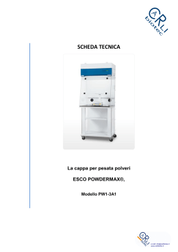
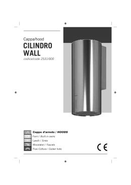
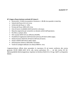
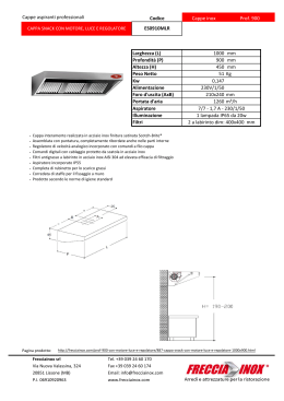
S4000
Cappa Isola / Island Hood 90 2442.090
Cappa Isola / Island Hood 120 2442.120
Cappe d'arredo / HOODS
Forni / Built-in ovens
Lavelli / Sinks
Miscelatori / Faucets
Piani Cottura / Cooker hobs
I taliano
ISTRUZIONI PER
L’INSTALLAZIONE, LA
MANUTENZIONE E L’USO DELLA
CAPPA ISOLA SERIE 4000
GENERALITA':
Prima di installare e utilizzare la cappa, leggereattentamente tutte le istruzioni riportate nel seguente manuale.
Si raccomanda di conservare accuratamente libretto e certificato di garanzia.
UTILIZZAZIONE:
La cappa appartiene al tipo ASPIRANTE; odori
evapori aspirati devono essere convogliati in un
condotto esterno di evacuazione.
E’ possibile trasformare la cappa in “Filtrante"
acquistando la confezione - Filtro in carbone
cod. 9700400.
DIMENSIONI DI MASSIMA
291
50
810-1220
612
291
295
295
98
595
2
-8
8
9
1
1
F11
ISTRUZIONI DI MONTAGGIO CAPPA
ISOLA SERIE 4000
OPERAZIONE N° 1
1aTogliere le due viti Z che fissano il tubo superiorealla struttura.N.B. tenere con le mani il
tubo superiore.
1b Far scorrere il tubo superiore verso il basso.
1c Togliere le viti V che fissano la struttura scorrevole a quella fissa.
OPERAZIONE N° 2
2aControllare l’altezza occorrente dal soffitto al
filoinferiore cappa lasciando 650/700 mm. dal
pianodelle griglie dei fuochi.
Z
Z
(fig. 2)
V
3
V
650-700
50
mm
max 1270
min 860
(fig. 1)
F11
OPERAZIONE N° 3
3aRiportare la misura desiderata dal filo inferiorecappa e la parte superiore dlla struttura scorrvole tirandola verso l’alto.
3bFissare la struttura con le viti V n° 2 per lato
(tot. n° 8).
N.B. Vi sono 3 fori per lato; il foro al centro non
si deve utilizzare.
ATTENZIONE
- I fori della struttura sono a passo 15 mm e
quindi occorre usare quelli piu’ vicino alla misura desiderata.
- E’ indicata, con apposito cartello, la misura
MAX in altezza che si puo’ ottenere garantendo la rigidita’ della struttura.
OPERAZIONE N° 4
4aTrovare il centro di fissaggio della cappa sul
soffitto.
4bUsare l’apposita maschera per segnare i 4 centri di foratura.
4c Forare con punta da 10 mm.
4d Inserire i Fischer ed avvitare le speciali barre
filettate con l’apposito inserto “CHIAVE TORX”
(T) in dotazione.
(fig. 3)
(fig. 4)
FISHER Ø 10
TORX
V
V
*
T
4
F11
OPERAZIONE N° 5
5aPortare la cappa verso il soffitto, inserire la struttura superiore nelle barre filettate e bloccarecon
le rondelle e dadi Y (n° 2 dadi per barra).
ATTENZIONE
- Bloccare con doppi dadi in modo da impedire
l’allentamento dovuto ad eventuali vibrazioni.
OPERAZIONE N° 6
6aEffettuare il collegamento del tubo di evacuazionefumi ed elettrico.
6bPortare il tubo scorrevole verso l’alto e bloccare con le viti Z.
(fig. 5)
(fig. 6)
Z
Y
5
Y
F11
COLLEGAMENTO ELETTRICO:
Prima di effettuare qualsiasi collegamento assicurarsi che la tensione di rete corrisponda a quella
riportata sull’etichetta posta all’interno dell’apparecchio.
Si consiglia di affidare il collegamento elettrico ad
un tecnico qualificato.
Apparecchio sprovvisto di spina: applicare una
spina a norme oppure un interruttore omnipolare
a norme con una distanza dei contatti in apertura
non inferiore a 3 mm. Il cavo di terra non deve
essere interrotto dall’interruttore.
Si declina ogni responsabilità per inconvenienti derivanti dall’inosservanza delle suddette disposizioni.
La ditta costruttrice si riserva di apportare
qualsiasi modifica senza preavviso.
PANNELLO DI COMANDO:
Il pannello di comando è di tipo elettronico ed è
posizionato nella parte anteriore della cappa.
FUNZIONE TASTI:
Accensione e spegnimento luci.
1 Accensione 1a velocità e spegnimento motore.
2 Accensione 2a velocità.
3 Accensione 3a velocità.
4 Accensione 4a velocità.
NOTE:
- Dopo 30 ore di funzionamento della cappa i led
dei “tasti 1,2,3,4” lampeggiano per 30 secondi a motore spento per segnalare la necessità
della pulizia dei Filtri.
N.B. Premendo “a lungo” il tasto “velocità 3”,
a motore spento, l’allarme viene RESETTATO.
- Il bordo perimetrale dei tasti rimane sempre illuminato. Per disattivarlo premere “a lungo” il
tasto “velocità 1” a motore spento.
N.B. Per riattivare l’illuminazione premere
sempre “a lungo” il tasto “velocità 1”.
- E’ possibile ritardare, automaticamente, lo spegnimento del motore premendo a lungo uno
dei tasti delle Velocità.
Il motore rimarrà acceso per altri 10 minuti.
6
F11
MANUTENZIONE:
Scollegare l’apparecchio dalla rete elettrica prima
di effettuare qualsiasi operazione di manutenzione.
1) Pulizia delle parti di acciaio inox: al fine di
evitare graffi sulle superfici si sconsiglia l’uso
di polveri abrasive o spazzole. Utilizzare detergenti liquidi specifici per acciaio inox.
2) Pulizia del filtro: smontare il filtro agendo sulla maniglia e lavarlo in lavastoviglie o con acqua saponata, evitando di strofinare con panni
o spugne.
Prima di riporre il filtro asciugarlo accuratamente.
ATTENZIONE
- L’aria espulsa non deve essere convogliata in
condotti che siano condivisi da altri apparecchi
alimentati con energia diversa da quella elettrica. (es. stufe a legna, stufa gas, caldaie a
combustibili ...)
- Qualora l’utilizzo della cappa sia contemporaneo ad altri apparecchi, alimentati con energia
diversa da quella elettrica, dovrà essere prevista un’adeguata aerazione del locale.
- E’ da escludere l’impiego di fiamma libera sotto
la cappa o la preparazione di cibi alla fiamma
poichè potrebbe dar luogo ad incendi.
Controllare che l’olio non si surriscaldi durante
le fritture onde evitare che prenda fuoco.
- L’inosservanza delle norme di pulizia dei filtri
comporta rischi d’incendio. Si raccomanda
quindi di attenersi alle istruzioni suggerite.
7
F11
IMPORTANTE:
il montaggio della cappa in presenza di altri apparecchi non elettrici (es. stufe a legna, stufa gas,
caldaie a combustibili ...) dovrà prevedere uno
scarico esterno che assicuri una buona aerazione. Verificare le condizioni del camino di scarico
nel caso in cui quest’ultimo sia rimasto inutilizzato
per molto tempo.
Ricordarsi inoltre di prestare la massima attenzione alle locali norme vigenti in materia di evacuazione fumi.
Tutti i suggerimenti forniti al riguardo devono essere scrupolosamente osservati al fine di evitare
spiacevoli inconvenienti.
IL COSTRUTTORE DECLINA OGNI RESPONSABILITA' DERIVANTE DAL MANCATO RISPETTO
DELLE INDICAZIONI FORNITE.
TABELLA CARATTERISTICHE TECNICHE
Tipo
ISOLA 90
ISOLA 120
2442.090
2442.120
898X595X50 mm
1198X595X50 mm
240-1000
240-1000
Sportelli per Asp. Perim.
n. 12 LED X 1 W
n. 18 LED X 1 W
1
1
3
4
4
4
inox spazzolato Foster
inox spazzolato Foster
362 W
8
368 W
F11
E nglish
INSTRUCTIONS
FOR INSTALLATION,
MAINTENANCE AND USE OF THE
S. 4000 ISLAND HOOD
GENERAL INFORMATION:
before installing and using the hood, read carefully
all instructions contained in the present handbook.
We suggest that you always keep the handbook
and the warranty certificate within easy reach.
USE:
the hood at issue is a SUCTION hood. The odours
and vapours coming from the motor shall be conveyed into and external exhaust duct.
The extractor hood can be converted into a
“Filtering” hood by purchasing the Carbon Filter pack – carbon filter cod. 9700400.
OUTLINE DIMENSIONS
291
50
810-1220
612
291
295
295
98
595
9
-8
8
9
1
1
F11
FIXING INSTRUCTIONS
ISLAND HOOD
FOR
S.4000
OPERATION 1
1aRemove the two screws Z which fix the top
pipe to the structure.
1b Let the top pipe slide downwards.
1c Remove the screws V which fix the sliding
structure to the fixed one.
OPERATION 2
2aCheck the necessary height from ceiling to
bottom cable of the hood leaving 650/700 mm
from the hob grids.
Z
Z
(fig. 2)
V
10 V
650-700
50
mm
max 1270
min 860
(fig. 1)
F11
OPERATION 3
3aReach the needed measure from bottom cable
of the hood to top part of the sliding structure
by pulling it upwards.
3bFix the structure with screws V using 2 of them
for each side (8 screws in total).
ATTENTION!
- There are 3 holes per side, DO NOT USE
THE CENTRAL HOLE.
- Since the holes of the structure are 15 mm
far from each other, use those nearest to the
required measure.
- The maximum height, which can be obtained
by granting the rigidness of the structure, is
indicated with an appropriate notice.
OPERATION 4
4aFind the fixing centre of the hood on the ceiling.
4b Use the appropriate jig to indicate the 4 drilling
centres.
4c Drill with 10 mm bit.
4d Insert the Fishers and screw the special threaded bars with the appropriate “TORX KEY” (T)
supplied in the package.
(fig. 3)
(fig. 4)
FISHER Ø 10
TORX
V
V
*
T
11 F11
OPERATION 5
5aTake the hood towards the ceiling, insert the top
structure into the threaded bars and fix it with
washers and nuts Y (2 nuts per bar).
ATTENTION!
Fix with double nuts in order to avoid the loosening due to vibrations.
OPERATION 6
6aConnect the fumes evacuation pipe and arrange the electrical connection.
6bTake the sliding pipe upwards and fix with
screws Z.
(fig. 5)
(fig. 6)
Z
Y
12 Y
F11
ELECTRICAL CONNECTIONS:
before carrying out any electrical connection, make
sure that the voltage corresponds to the one mentioned on the label located on the inside of the appliance. It is advisable to entrust the installation of
the electrical connection to a qualified technician.
Appliance provided without plug: please connect a plug or an omni-polar switch in compliance
to the existing local regulations, and with an opening connection distance not inferior to 3 mm, The
earth wire must not be interrupted by the switch.
Foster decline any responsibility for any inconveniences deriving from the non-observance of the aforesaid instructions of the use
of materials which are not in compliance with
the existing regulations.
CONTROL PANEL:
The control panel is electronic and is positioned in
the lower-end part of the hood.
FUNCTION OF BUTTONS:
SWITCHED OFF
1) TURN-ON 1st SPEED AND MOTOR TURNOFF
2) TURN-ON 2nd SPEED
3) TURN-ON 3rd SPEED
4) TURN-ON 4th SPEED
REMARKS:
- After 30 hours use of the hood, indicators of
keys 1,2,3,4 flash for 30 seconds to signal the
need to clean filters.
ATTENTION!
The alarm can be reset by pressing for long
speed key n° 3 with engine switched off.
- The keys perimetric edge remains always
lighted. To deactivate it, press for long speed
key n° 1 with engine switched off.
ATTENTION!
To reactivate the lighting, press for long speed
key n° 1.
- It is possible to automatically delay the stalling
of the engine by pressing for long one of the
speed keys.
The engine will run for others 10 minutes.
13 F11
MAINTENANCE:
Please switch-off the electrical power, or disconnect the appliance before carrying out any maintenance operation.
1) Cleaning of the stainless steel parts: in order
to avoid scratches in the steel surfaces, please
don’t use abrasive powders or brushes. Use liquid detergents specifically made for stainless
steel items.
2) Filter Cleaning: Remove the filter from the
container and wash it in the dishwasher or with
soapy water, without rubbing it with a cloth or
a sponge.
Before replacing the filter, carefully dry it without deforming it.
ATTENTION:
- The expelled air must not be convoyed in ducts
which are shared by other appliances powered
with energy different from the electrical one.
- Should the use of the hood be contemporaneous to other appliances powered by energy
different from the electrical one, an adequate
ventilation on the room is to be foreseen.
- The use of an open flame under the hood or
the preparation of food with an open flame is to
be excluded, as this could cause a fire. Check
that the oil doesn’t overheat during the frying
process in order to prevent it from catching fire.
- The non-compliance to filter cleaning recommendations, causes a risk of fire. It is of course
recommended to follow the said instructions
14 F11
IMPORTANT:
The use of the hood in presence of other nonelectrical appliances (such as, but not limited to,
wood-burning stoves, gas stoves, non-electrical
water-heaters) requires the presence of an external exhaust which ensures a good ventilation of the
room.
Verify the conditions of the exhaust chimney in case
the hood is not used for a long period of time.
Please also pay the maximum attention to the local
standard regulations concerning exhaust scavenging.
All recommendations on the subject should be
scrupulously observed in order to avoid unpleasant
inconveniences.
THE MANUFACTURER DECLINES ANY RESPONSIBILITY CAUSED BY NON-COMPLIANCE TO THE HERE ABOVE MENTIONED RECOMMENDATIONS.
TECHNICAL FEATURES:
ISLAND 120
Type
ISLAND 90
Code
2442.090
2442.120
898X595X50 mm
1198X595X50 mm
Dimensions
Capacity
240-1000
240-1000
n. 12 LED X 1 W
n. 18 LED X 1 W
Anti-grease filters
1
1
Perimetric suction elements
3
4
Working speed
4
4
inox spazzolato Foster
inox spazzolato Foster
Cooking surface lighting
Operation
Finishing
Air outlet diameter
Voltage
Frequency
Max absorbed Power
15 362 W
368 W
F11
Grafica e Stampa: SERIART - www.seriart.com
F11 (09-09)
via M.S. Ottone, 18/20 - Brescello (RE)
ASSISTENZA TECNICA Tel. 0522/684450 - FAX 686019 MAIL [email protected]
MAGAZZINO RICAMBI Tel. / FAX 0522/684300 MAIL [email protected]
Scaricare