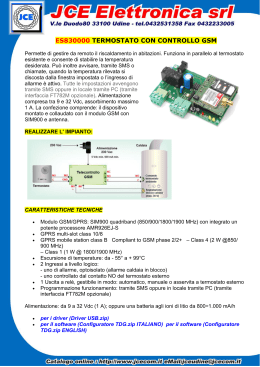
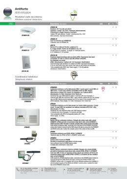
Combinatore Telefonico
GSM telephone dialler
GSM11 - GSM21
1
2
3
4
1
7
4
5
2
8
5
0
8
6
3
9
6
7
IT
9
0
EN
GSM10-GSM20
Manuale Installazione
Installation manual
28-02-11/24800172
GSM_Inst_ITA_24800172 28-02-11.indd 1
28/02/11 16.34
Manuale Installatore
Grazie per aver acquistato il combinatore telefonico BRAHMS.
Questo prodotto riunisce in un unico dispositivo le seguenti funzioni:
- Segnalazione locale e remota di stato d’allarme dei dispositivi collegati agli ingressi (o di guasto) e relativi ripristini;
- Interrogazione di stato e di credito residuo via SMS;
- Tele-soccorso con funzione viva-voce;
- Telecomando GSM a costo zero (Funzione CLIP);
- Tele-ascolto ambientale su rete GSM;
- Funzionalità di centrale di allarme;
- Personalizzazione dei messaggi d’allarme
IT
CONTENUTO DELL’IMBALLO
Nella confezione del combinatore telefonico è presente:
- Manualistica: “Manuale per l’installatore”, “Manuale di Programmazione” (solo per i modelli con tastiera e display)
- Combinatore telefonico.
Nella confezione non sono incluse le batterie, i tasselli di fissaggio a parete e i cavi di collegamento alla rete di alimentazione.
m Importante!
• Il Combinatore può essere programmato via PC utilizzando l’apposito applicativo GSMMANAGER.
La versione aggiornata del programma può essere scaricata dal sito internet: www.Bpt.it alla sezione
“Download”>“Software”.
Per accedere al download è necessario essere registrati al sito.
CODICE MASTER DI DEFAULT
111999
SMALTIMENTO
Assicurarsi che il materiale d’imballaggio non venga
disperso nell’ambiente, ma smaltito seguendo le norme
vigenti nel paese di utilizzo del prodotto.
Alla fine del ciclo di vita dell’apparecchio evitare che lo
stesso venga disperso nell’ambiente.
Lo smaltimento dell’apparecchiatura deve essere effettuato rispettando le norme vigenti e privilegiando il riciclaggio delle sue parti costituenti.
2
GSM_Inst_ITA_24800172 28-02-11.indd 2
28/02/11 16.34
Manuale Installatore
m
NOTE DI SICUREZZA
m
• Leggere attentamente le istruzioni, prima di iniziare l’installazione.
• Dopo aver tolto l’imballaggio assicurarsi dell’integrità dell’apparecchio. Gli elementi dell’imballaggio (sacchetti in
plastica, polistirolo espanso, ecc.) non devono essere lasciati alla portata dei bambini in quanto potenziali fonti di
pericolo.
• Prima di collegare l’apparecchio accertarsi che tensione e corrente disponibili per l’alimentazione del dispositivo
siano rispondenti a quelli indicati nei dati di targa.
• Prima di effettuare qualunque operazione di pulizia o di manutenzione, scollegare l’apparecchio dalla rete di alimentazione elettrica.
• È vietato utilizzare il prodotto per scopi diversi da quelli previsti o impropri: il costruttore non può essere considerato responsabile per eventuali danni derivanti da usi impropri, erronei ed irragionevoli.
• È vietato manomettere o modificare il prodotto.
• Eseguire gli interventi come specificato dal costruttore.
• La rimozione delle etichette poste sul prodotto farà decadere la garanzia.
• L’installazione, la programmazione, la messa in servizio e la manutenzione del prodotto devono essere effettuate
soltanto da personale tecnico qualificato ed opportunamente addestrato nel rispetto delle normative vigenti.
• Al termine dell’installazione verificare sempre il corretto funzionamento dell’apparecchiatura e dell’impianto nel
suo insieme.
• Non installare il dispositivo all’esterno o in luoghi dove il dispositivo sia sottoposto a stillicidio o a spruzzi d’acqua.
• Prestare attenzione a posizionare il combinatore in luogo pulito secco e non soggetto a vibrazioni o urti di alcun
genere.
• Trattare con cura il dispositivo, contiene parti elettroniche fragili e sensibili all’umidità. Le schede elettroniche
possono essere seriamente danneggiate dalle scariche elettrostatiche: qualora vi sia bisogno di maneggiarle indossare idonei indumenti e calzature anti statiche o, almeno, assicurarsi preventivamente di aver rimosso ogni carica
residua toccando con la punta delle dita una superficie metallica connessa all’impianto di terra (es. lo chassis di un
elettrodomestico).
IT
y Nota
Prima di eseguire l’installazione del combinatore è indispensabile verificare che, nel luogo in cui si intende installare
il dispositivo, vi sia un livello adeguato del segnale GSM: per fare ciò è sufficiente inserire la SIM-CARD acquistata per
il combinatore in un telefono cellulare e verificarne la ricezione.
Nel caso la ricezione non risulti di buona qualità, sarà necessario installare il dispositivo in un altro luogo, ove ci sia
una migliore qualità del segnale oppure utilizzare in alternativa l’antenna esterna opzionale.
Resta inteso che la società BRAHMS S.r.l. non assume alcuna responsabilità in relazione al mancato invio, mancata
ricezione o ritardato invio o ritardata ricezione del messaggio SMS da parte del combinatore, quando si tratti di fatto
imputabile alla ricezione del relativo segnale o a problemi di qualunque tipo che attengano all’attività del gestore
di telefonia;
Le SIM-CARD di alcuni Provider sono soggette a scadenza : si consiglia di tenerne conto al momento della programmazione del combinatore.
3
GSM_Inst_ITA_24800172 28-02-11.indd 3
28/02/11 16.34
Manuale Installatore
INDICE
PREMESSA . . . . . . . . . . . . . . . . . . . . . . . . . . . . . . . . . . . . . . . . . . . . . . . . . . . . . . . . . . . . . . . . . . . . . . . . . . . . . . . . . . . . . . . . . . . . . Pag. 6
Caratteristiche Base . . . . . . . . . . . . . . . . . . . . . . . . . . . . . . . . . . . . . . . . . . . . . . . . . . . . . . . . . . . . . . . . . . . . . . . . . . . . . . . . . . . . . . . . . . . 6
Utilizzo e Applicazioni . . . . . . . . . . . . . . . . . . . . . . . . . . . . . . . . . . . . . . . . . . . . . . . . . . . . . . . . . . . . . . . . . . . . . . . . . . . . . . . . . . . . . . . . 6
SCHEMA GENERALE . . . . . . . . . . . . . . . . . . . . . . . . . . . . . . . . . . . . . . . . . . . . . . . . . . . . . . . . . . . . . . . . . . . . . . . . . . . . . . . . . Pag. 7
DESCRIZIONE DELLA SCHEDA ELETTRONICA . . . . . . . . . . . . . . . . . . . . . . . . . . . . . . . . . . . . . . . . . . . . . . . . Pag. 8
CARATTERISTICHE TECNICHE GENERALI . . . . . . . . . . . . . . . . . . . . . . . . . . . . . . . . . . . . . . . . . . . . . . . . . . . . . . Pag.10
IT
ISTRUZIONI PER IL MONTAGGIO . . . . . . . . . . . . . . . . . . . . . . . . . . . . . . . . . . . . . . . . . . . . . . . . . . . . . . . . . . . . . . . . Pag.12
Inserimento Sim-Card . . . . . . . . . . . . . . . . . . . . . . . . . . . . . . . . . . . . . . . . . . . . . . . . . . . . . . . . . . . . . . . . . . . . . . . . . . . . . . . . . . . . . . . . 13
Alloggiamento delle batterie . . . . . . . . . . . . . . . . . . . . . . . . . . . . . . . . . . . . . . . . . . . . . . . . . . . . . . . . . . . . . . . . . . . . . . . . . . . . . . . . 13
MESSA IN SERVIZIO . . . . . . . . . . . . . . . . . . . . . . . . . . . . . . . . . . . . . . . . . . . . . . . . . . . . . . . . . . . . . . . . . . . . . . . . . . . . . . . . . Pag.14
UTILIZZO DEL COMBINATORE . . . . . . . . . . . . . . . . . . . . . . . . . . . . . . . . . . . . . . . . . . . . . . . . . . . . . . . . . . . . . . . . . . . . Pag.15
Pannello di controllo . . . . . . . . . . . . . . . . . . . . . . . . . . . . . . . . . . . . . . . . . . . . . . . . . . . . . . . . . . . . . . . . . . . . . . . . . . . . . . . . . . . . . . . . . 15
Funzionalità dei led . . . . . . . . . . . . . . . . . . . . . . . . . . . . . . . . . . . . . . . . . . . . . . . . . . . . . . . . . . . . . . . . . . . . . . . . . . . . . . . . . . . . . . . . . . 15
Funzioni principali da tastiera . . . . . . . . . . . . . . . . . . . . . . . . . . . . . . . . . . . . . . . . . . . . . . . . . . . . . . . . . . . . . . . . . . . . . . . . . . . . . . . 15
Registrazione dei Messaggi Vocali Personalizzabili via DTMF . . . . . . . . . . . . . . . . . . . . . . . . . . . . . . . . . . . . . . . . . . . . . . 16
Controllo delle uscite via DTMF . . . . . . . . . . . . . . . . . . . . . . . . . . . . . . . . . . . . . . . . . . . . . . . . . . . . . . . . . . . . . . . . . . . . . . . . . . . . . . 17
Risposta su chiamata d’allarme . . . . . . . . . . . . . . . . . . . . . . . . . . . . . . . . . . . . . . . . . . . . . . . . . . . . . . . . . . . . . . . . . . . . . . . . . . . . . . 17
Programmazione e Modifica della Rubrica Telefonica via SMS . . . . . . . . . . . . . . . . . . . . . . . . . . . . . . . . . . . . . . . . . . . . . 18
Comandi SMS . . . . . . . . . . . . . . . . . . . . . . . . . . . . . . . . . . . . . . . . . . . . . . . . . . . . . . . . . . . . . . . . . . . . . . . . . . . . . . . . . . . . . . . . . . . . . . . . 19
GENERALITÀ SULLA PROGRAMMAZIONE DEL COMBINATORE . . . . . . . . . . . . . . . . . . . . . . . . . . Pag.21
Programmazione degli Utenti . . . . . . . . . . . . . . . . . . . . . . . . . . . . . . . . . . . . . . . . . . . . . . . . . . . . . . . . . . . . . . . . . . . . . . . . . . . . . . . 21
CODICE . . . . . . . . . . . . . . . . . . . . . . . . . . . . . . . . . . . . . . . . . . . . . . . . . . . . . . . . . . . . . . . . . . . . . . . . . . . . . . . . . . . . . . . . . . . . . . . . . . . . . 21
NUMERO TELEFONICO . . . . . . . . . . . . . . . . . . . . . . . . . . . . . . . . . . . . . . . . . . . . . . . . . . . . . . . . . . . . . . . . . . . . . . . . . . . . . . . . . . . . . . 21
PRIORITÀ . . . . . . . . . . . . . . . . . . . . . . . . . . . . . . . . . . . . . . . . . . . . . . . . . . . . . . . . . . . . . . . . . . . . . . . . . . . . . . . . . . . . . . . . . . . . . . . . . . . . 21
RICEZIONE SMS DA PROVIDER . . . . . . . . . . . . . . . . . . . . . . . . . . . . . . . . . . . . . . . . . . . . . . . . . . . . . . . . . . . . . . . . . . . . . . . . . . . . . . 21
NOTIFICA ALLARMI . . . . . . . . . . . . . . . . . . . . . . . . . . . . . . . . . . . . . . . . . . . . . . . . . . . . . . . . . . . . . . . . . . . . . . . . . . . . . . . . . . . . . . . . . 22
CLIP . . . . . . . . . . . . . . . . . . . . . . . . . . . . . . . . . . . . . . . . . . . . . . . . . . . . . . . . . . . . . . . . . . . . . . . . . . . . . . . . . . . . . . . . . . . . . . . . . . . . . . . . . 22
NOTIFICA CLIP . . . . . . . . . . . . . . . . . . . . . . . . . . . . . . . . . . . . . . . . . . . . . . . . . . . . . . . . . . . . . . . . . . . . . . . . . . . . . . . . . . . . . . . . . . . . . . 22
Personalizzazione testo SMS . . . . . . . . . . . . . . . . . . . . . . . . . . . . . . . . . . . . . . . . . . . . . . . . . . . . . . . . . . . . . . . . . . . . . . . . . . . . . . . . 22
Programmazione degli Ingressi . . . . . . . . . . . . . . . . . . . . . . . . . . . . . . . . . . . . . . . . . . . . . . . . . . . . . . . . . . . . . . . . . . . . . . . . . . . . . 23
TIPO INGRESSO . . . . . . . . . . . . . . . . . . . . . . . . . . . . . . . . . . . . . . . . . . . . . . . . . . . . . . . . . . . . . . . . . . . . . . . . . . . . . . . . . . . . . . . . . . . . . 23
FUNZIONALITÀ INGRESSO . . . . . . . . . . . . . . . . . . . . . . . . . . . . . . . . . . . . . . . . . . . . . . . . . . . . . . . . . . . . . . . . . . . . . . . . . . . . . . . . . . 23
INGRESSO RITARDATO . . . . . . . . . . . . . . . . . . . . . . . . . . . . . . . . . . . . . . . . . . . . . . . . . . . . . . . . . . . . . . . . . . . . . . . . . . . . . . . . . . . . . . 23
SMS AL RIPRISTINO . . . . . . . . . . . . . . . . . . . . . . . . . . . . . . . . . . . . . . . . . . . . . . . . . . . . . . . . . . . . . . . . . . . . . . . . . . . . . . . . . . . . . . . . . 23
ABILITAZIONE INGRESSO . . . . . . . . . . . . . . . . . . . . . . . . . . . . . . . . . . . . . . . . . . . . . . . . . . . . . . . . . . . . . . . . . . . . . . . . . . . . . . . . . . . . 24
FILTRO . . . . . . . . . . . . . . . . . . . . . . . . . . . . . . . . . . . . . . . . . . . . . . . . . . . . . . . . . . . . . . . . . . . . . . . . . . . . . . . . . . . . . . . . . . . . . . . . . . . . . . 24
PARZIALE . . . . . . . . . . . . . . . . . . . . . . . . . . . . . . . . . . . . . . . . . . . . . . . . . . . . . . . . . . . . . . . . . . . . . . . . . . . . . . . . . . . . . . . . . . . . . . . . . . . . 24
4
GSM_Inst_ITA_24800172 28-02-11.indd 4
28/02/11 16.34
Manuale Installatore
INDICE
Programmazione delle Uscite . . . . . . . . . . . . . . . . . . . . . . . . . . . . . . . . . . . . . . . . . . . . . . . . . . . . . . . . . . . . . . . . . . . . . . . . . . . . . . .
TIPO DI USCITA . . . . . . . . . . . . . . . . . . . . . . . . . . . . . . . . . . . . . . . . . . . . . . . . . . . . . . . . . . . . . . . . . . . . . . . . . . . . . . . . . . . . . . . . . . . . . .
EVENTO ATTIVAZIONE . . . . . . . . . . . . . . . . . . . . . . . . . . . . . . . . . . . . . . . . . . . . . . . . . . . . . . . . . . . . . . . . . . . . . . . . . . . . . . . . . . . . . .
USCITA ATTIVA . . . . . . . . . . . . . . . . . . . . . . . . . . . . . . . . . . . . . . . . . . . . . . . . . . . . . . . . . . . . . . . . . . . . . . . . . . . . . . . . . . . . . . . . . . . . . .
Programmazione Parametri Generali . . . . . . . . . . . . . . . . . . . . . . . . . . . . . . . . . . . . . . . . . . . . . . . . . . . . . . . . . . . . . . . . . . . . . . .
LINGUA . . . . . . . . . . . . . . . . . . . . . . . . . . . . . . . . . . . . . . . . . . . . . . . . . . . . . . . . . . . . . . . . . . . . . . . . . . . . . . . . . . . . . . . . . . . . . . . . . . . . .
SEQUENZA CICLICA . . . . . . . . . . . . . . . . . . . . . . . . . . . . . . . . . . . . . . . . . . . . . . . . . . . . . . . . . . . . . . . . . . . . . . . . . . . . . . . . . . . . . . . . .
TERMINE CICLO . . . . . . . . . . . . . . . . . . . . . . . . . . . . . . . . . . . . . . . . . . . . . . . . . . . . . . . . . . . . . . . . . . . . . . . . . . . . . . . . . . . . . . . . . . . . .
NUMERO TENTATIVI . . . . . . . . . . . . . . . . . . . . . . . . . . . . . . . . . . . . . . . . . . . . . . . . . . . . . . . . . . . . . . . . . . . . . . . . . . . . . . . . . . . . . . . . .
PAUSA FRA TENTATIVI . . . . . . . . . . . . . . . . . . . . . . . . . . . . . . . . . . . . . . . . . . . . . . . . . . . . . . . . . . . . . . . . . . . . . . . . . . . . . . . . . . . . . . .
MESSAGGIO IMPIANTO . . . . . . . . . . . . . . . . . . . . . . . . . . . . . . . . . . . . . . . . . . . . . . . . . . . . . . . . . . . . . . . . . . . . . . . . . . . . . . . . . . . . .
LUNGHEZZA RITARDO . . . . . . . . . . . . . . . . . . . . . . . . . . . . . . . . . . . . . . . . . . . . . . . . . . . . . . . . . . . . . . . . . . . . . . . . . . . . . . . . . . . . . .
MESSAGGIO ESISTENZA VITA . . . . . . . . . . . . . . . . . . . . . . . . . . . . . . . . . . . . . . . . . . . . . . . . . . . . . . . . . . . . . . . . . . . . . . . . . . . . . . . .
VISUALIZZAZIONE NUMERO . . . . . . . . . . . . . . . . . . . . . . . . . . . . . . . . . . . . . . . . . . . . . . . . . . . . . . . . . . . . . . . . . . . . . . . . . . . . . . . .
GESTIONE CREDITO . . . . . . . . . . . . . . . . . . . . . . . . . . . . . . . . . . . . . . . . . . . . . . . . . . . . . . . . . . . . . . . . . . . . . . . . . . . . . . . . . . . . . . . . .
SICUREZZA POSITIVA . . . . . . . . . . . . . . . . . . . . . . . . . . . . . . . . . . . . . . . . . . . . . . . . . . . . . . . . . . . . . . . . . . . . . . . . . . . . . . . . . . . . . . . .
Memoria Eventi . . . . . . . . . . . . . . . . . . . . . . . . . . . . . . . . . . . . . . . . . . . . . . . . . . . . . . . . . . . . . . . . . . . . . . . . . . . . . . . . . . . . . . . . . . . . . .
Programmazione Funzione Barrier . . . . . . . . . . . . . . . . . . . . . . . . . . . . . . . . . . . . . . . . . . . . . . . . . . . . . . . . . . . . . . . . . . . . . . . . . .
NUMERO TELEFONO UTENTE . . . . . . . . . . . . . . . . . . . . . . . . . . . . . . . . . . . . . . . . . . . . . . . . . . . . . . . . . . . . . . . . . . . . . . . . . . . . . . .
24
24
24
24
25
25
25
25
25
25
25
25
25
25
25
25
26
26
26
IT
PROGRAMMAZIONE E COMANDI AVANZATI VIA SMS . . . . . . . . . . . . . . . . . . . . . . . . . . . . . . . . . . . . . . Pag.27
SMS di Programmazione . . . . . . . . . . . . . . . . . . . . . . . . . . . . . . . . . . . . . . . . . . . . . . . . . . . . . . . . . . . . . . . . . . . . . . . . . . . . . . . . . . . . . 27
SMS di Comando . . . . . . . . . . . . . . . . . . . . . . . . . . . . . . . . . . . . . . . . . . . . . . . . . . . . . . . . . . . . . . . . . . . . . . . . . . . . . . . . . . . . . . . . . . . . . 30
PARAMETRI DI DEFAULT . . . . . . . . . . . . . . . . . . . . . . . . . . . . . . . . . . . . . . . . . . . . . . . . . . . . . . . . . . . . . . . . . . . . . . . . . . . Pag.32
SMS di Default . . . . . . . . . . . . . . . . . . . . . . . . . . . . . . . . . . . . . . . . . . . . . . . . . . . . . . . . . . . . . . . . . . . . . . . . . . . . . . . . . . . . . . . . . . . . . . . 33
Messaggi Vocali di Default . . . . . . . . . . . . . . . . . . . . . . . . . . . . . . . . . . . . . . . . . . . . . . . . . . . . . . . . . . . . . . . . . . . . . . . . . . . . . . . . . . . 33
5
GSM_Inst_ITA_24800172 28-02-11.indd 5
28/02/11 16.34
Manuale Installatore-Descrizione della Scheda Elettronica
PREMESSA
Il presente manuale descrive il funzionamento dei combinatori GSM della serie GSM.
La serie GSM è una famiglia di combinatori GSM che offrono la possibilità di inviare allarmi via SMS o vocalmente.
È possibile registrare fino a 5 messaggi vocali per un massimo di 20 numeri di telefono. Gli ingressi di allarme sono programmabili come NA o NC e possono essere attivati con positivo/negativo a dare o a mancare.
Ogni ingresso è in grado di inviare un messaggio vocale o SMS oppure entrambi.
Nel caso di attivazione di un ingresso, il dispositivo chiama tutti i numeri di telefono assegnati a quel dato ingresso, un
numero di volte pari al numero di tentativi programmati.
IT
La serie di combinatori GSM è composta da 4 modelli che si differenziano per il numero di utenti, il numero di ingressi,
personalizzazione dei messaggi vocali e altre funzioni speciali:
Il modello GSM10 è un combinatore con 2 Ingressi, 4 Uscite, 3 messaggi personalizzabili e 20 Utenti;
Il modello GSM11 è un combinatore con tastiera e display con 2 Ingressi, 4 uscite, 3 messaggi personalizzabili e 20 Utenti;
Il modello GSM20 è un combinatore con 4 Ingressi, 4 Uscite, 5 messaggi personalizzabili e 20 Utenti;
Il modello GSM21 è un combinatore con tastiera e display, che incorpora funzionalità evolute di centrale di allarme, con 4
Ingressi, 4 Uscite, 5 messaggi personalizzabili, 20 Utenti e 50 utenti barrier.
Caratteristiche Base
• Modulo GSM integrato,
• 2/4 ingressi di allarme (programmabili NA – NC),
• 4 uscite controllabili anche remotamente (Via SMS – Clip, Toni DTMF),
• 4 messaggi di allarme vocali + 1 messaggio di indirizzo,
• 1 SMS per ogni ingresso di allarme (max. 20 caratteri per ogni SMS),
• 20 utenti per le notifiche di allarme,
• Sequenza di chiamate programmabile,
• Funzione di ascolto ambientale,
• Funzione di Telesoccorso,
• 4 LED di controllo,
• Microfono e speaker integrati,
• Conforme CEI 79-2.
Utilizzo e Applicazioni
Il GSM fornisce differenti informazioni sullo stato del segnale GSM e può trasmettere messaggi di allarme di varia natura.
Tra le principali applicazioni troviamo:
- Segnalazione guasti di apparecchiature (ad esempio dispositivi elettromeccanici).
- Comando di apparecchiature da remoto (ad esempio cancelli o caldaie).
- Segnalazione di allarmi per edifici, veicoli, roulette, camper o natanti (ad esempio barche al largo o attraccate).
- Teleascolto ambientale remoto (ad esempio monitoraggio locali o montacarichi).
- Controllo di sensori di vario tipo (ad esempio sensori di temperatura o di allarme.
- Notifica di condizioni di emergenza (allarmi rapina o soccorso).
6
GSM_Inst_ITA_24800172 28-02-11.indd 6
28/02/11 16.34
Manuale Installatore-Descrizione della Scheda Elettronica
SCHEMA GENERALE
Comandi e
personalizzazioni
Antenna
esterna
opzionale
®
IT
Notifica allarmi
fino a 20 utenti
Programmazione
SW5
1
SW6
SW1
4
SW4
SW3
SW2
SW7
7
SW8
SW9
2
SW10
5
SW11
8
SW12
SW13
3
SW14
6
SW15
9
SW16
0
NA1
NC1
SW25
M2
M1
+
–
NC
C
NO
+
01
02
03
04 RST
–
I1
–
I2
I3
–
I4
VCC AOUT AIN GND
EXT
EXT
CN2
LOCK
CN1
RL2
C2
NC2
NA3
RL3
C3
NC3
NA4
RL4
C4
NC4
Modulo 4 uscite
relè opzionale
Ascolto
Ambientale
Da GSM attivazione e conferma a costo zero
Centrale
d’allarme
2/4 Ingressi 4 Uscite
Open Collector
7
GSM_Inst_ITA_24800172 28-02-11.indd 7
28/02/11 16.34
Manuale Installatore-Descrizione della Scheda Elettronica
DESCRIZIONE DELLA SCHEDA ELETTRONICA
CN6
SW1
B
SW23
SW22
SW21
SW20
SW19
1
CN1
DL1
SW9
SW13
SW6
SW10
SW14
SW7
SW11
SW15
SW8
SW12
SW16
+ I I +
SPK MIC
SW2
LOCK
IT
SW4
SW3
SW5
CN2
SW25
M1
+12 V –
NC
C
NO
+
01
02
1 Slot per l’inserimento della SIM-CARD
CONNETTORI
CN6
CN2
CN1
MORSETTI
+ 12V –
NC, C, NO
+, –
M1
01, 02, 03, 04
RST
I1, I2, I3, I4
JUMPER
SW22 (inserito)
SW21 (inserito)
SW20 (inserito)
SW19 (inserito)
SW25 (inserito)
LED
DL1
03
04 RST
–
I1
–
I2
I3
–
I4
B Tamper
SIGNIFICATO
Connettore seriale per il collegamento del PC
Connettore opzionale di ascolto locale (solo GSM20 e GSM21)
Connettore modulo opzionale uscite relè
SIGNIFICATO
Terra funzionale (miglior schermatura da disturbi e interferenze)
Alimentazione dispositivo 11÷14 Vcc
Uscita guasto
Alimentazione ausiliaria protetta per dispositivi esterni 11÷14 Vcc 40 mA
Uscite (Open Collector)
L’ingresso di Reset (RST) consente il blocco del ciclo di chiamate. Assume anche la
funzione di ingresso di comando per l’inserimento/disinserimento del combinatore.
Ingressi
SIGNIFICATO
Abilitazione/Disabilitazione Tamper.
Se aperto Tamper abilitati.
Protezione della programmazione da remoto.
Se aperto programmazione e comandi da remoto saranno accettati solo dagli
utenti in rubrica.
Ripristino programmazione di default.
Se aperto ripristina la programmazione di default
Aggiornamento tecnico (Non Rimuovere)
Rimozione/Inserimento della SIM-CARD.
Se disinserito permette la Rimozione/Inserimento della SIM-CARD a combinatore
alimentato
COLORE
STATO
SIGNIFICATO
Lampeggiante
Comunicazione con rete GSM OK
Rosso
Fisso o Spento
Non c’è comunicazione con la rete GSM
8
GSM_Inst_ITA_24800172 28-02-11.indd 8
28/02/11 16.34
Manuale Installatore
IT
9
GSM_Inst_ITA_24800172 28-02-11.indd 9
28/02/11 16.34
Manuale Installatore-Caratteristiche Tecniche Generali
CARATTERISTICHE TECNICHE GENERALI
GSM10
GSM11
GSM20
GSM21
Caratteristiche Generali
Alimentazione
11÷14 Vcc
Batteria di Back-up a bordo
3 x AA nichel metalidrato (fornite in opzione)
Durata batterie in stand-by
10 h
Protezione carica batterie
Assorbimenti in stand-by
Si
0,1 A
0,15 A
Assorbimenti in trasmissione dati
IT
IT
0,1 A
Extra assorbimento con batterie in ricarica
0,3 A
Modulo GSM dual band
900/1800 MHz
Temperatura di funzionamento
Range -5°+40°
Tamper Antiapertura
Si
Tamper Antistrappo
Si
Materiale contenitore
ABS Bianco
Grado di Protezione
Antenna remotizzabile
IP40
-
-
Livello di Sicurezza CEI 79-2
Opzionale
Opzionale
II°
Caratteristiche Prodotto
Numero Ingressi
Tipo ingressi programmabili
0,15 A
0,4 A
2
4
Negativo a dare; Negativo a mancare, Positivo a dare; Positivo a
Mancare,
Ingresso di reset del ciclo di chiamate
1
Numero uscite (open collector)
4 (per 100 mA)
Uscita aggiuntiva di guasto (relè a sicurezza
positiva o negativa)
Si (stato linea, mancanza rete, batteria in esaurimento)
Modulo uscite relè (C4MO0401)
Opzionale con montaggio a bordo
Uscite controllabili da remoto
Tutte
Numeri di telefono memorizzabili
20
Tipologia SIM-CARD utilizzabile
Standard (Voce+SMS)
Funzioni Hardware
Tastiera 10 tasti numerici+2 tasti funzioni+4
tasti Joy Stick
-
Si
Display 16x2 righe
-
Si
Funzionalità DTMF
20+50 (Barrier)
-
Si
-
Si
Si
Feedback acustico tastiera (beep)
-
Si
-
Si
Funzione ascolto ambiente da remoto
-
-
Si (opzionale)
Si (opzionale)
-
Si
-
Si
Led di stato
Segnalazione livello GSM
Modulo 4 uscite relè (1 A)
4
Opzionale su tutti i modelli
10
GSM_Inst_ITA_24800172 28-02-11.indd 10
28/02/11 16.34
Manuale Installatore-Caratteristiche Tecniche Generali
GSM10
GSM11
GSM20
GSM21
Programmazione del dispositivo
Programmazione con Tastiera display
Programmazione
(GSMMANAGER)
via
software
-
Si
PC
-
Si
Si
Programmazione via SMS
Si
Funzioni Principali
Comandi da remoto via SMS
Si
Comandi da remoto DTMF
Si
Funzione Clip
Si
Gestione del credito residuo
Si (inoltro messaggi ricevuti dal Provider o richiesta utente)
Funzionalità base antintrusione
Si
-
-
Orologio
Memoria eventi
Messaggi vocali personalizzabili
Modalità di personalizzazione
Si/Barrier
-
50 visualizzabili
Messaggi vocali
50 visualizzabili
Si
Si (Allarme Ingresso 1, 2, 3 e 4, Manomissione, Mancanza Rete,
Mancanza Batteria)
3
5
Via chiamata telefonica
Durata messaggi registrabili singolarmente
5 sec (per ingressi) - 10 sec (per indirizzo)
Messaggi SMS
Messaggi di Allarme personalizzabili
Si (allarmi sugli ingressi e relativi ripristini)
Tipologia di personalizzazione
Lunghezza SMS allarme personalizzabile
Messaggi di stato via SMS
Messaggio periodico di esistenza in vita
Protezione contro riempimento SIM-CARD
IT
Si
Si
-
Trasmissione vocale allarmi
Messaggi di allarme preregistrati
Si
Tramite SMS, Tastiera o Pc
20 digit
Si
Si con periodicità configurabile
Si (cancellazione rolling di 5 SMS)
11
GSM_Inst_ITA_24800172 28-02-11.indd 11
28/02/11 16.34
Manuale Installatore-Istruzioni per il Montaggio
ISTRUZIONI PER IL MONTAGGIO
Il montaggio del combinatore deve essere effettuato in
una zona facilmente accessibile, pertanto è necessario
lasciare una zona libera da ingombri lungo tutto il perimetro del combinatore.
Per l’installazione del combinatore si deve procedere
come di seguito indicato:
Aprire il coperchio svitando la vite posta sul lato (fig. 1).
Sollevare il coperchio del combinatore (fig. 2).
Utilizzando la dima in dotazione segnare la posizione
dei fori di fissaggio, assicurandosi che nel punto prescelto la parete sia piana.
IT
IT
fig. 1
Forare la parete che alloggerà il combinatore e introdurre i tasselli necessari al fissaggio del contenitore.
Fissare saldamente il fondo del combinatore alla parete
assicurandosi che il tamper (evidenziato in fig. 3) con
funzione antimanomissione scatti correttamente.
fig. 2
fig. 3
12
GSM_Inst_ITA_24800172 28-02-11.indd 12
28/02/11 16.34
Manuale Installatore-Istruzioni per il Montaggio
Inserimento Sim-Card
Alloggiamento scheda SIM-CARD
Per poter funzionare il dispositivo deve essere dotato di
una scheda SIM-CARD, non inclusa nella confezione da
inserire nell’apposito alloggiamento.
La SIM-CARD deve essere inserita a combinatore completamente spento (disalimentato).
Se la scheda SIM-CARD è nuova, prima di inserirla nel
combinatore, effettuare una chiamata inserendola in un
cellulare in modo da permettere al Provider di registrare
la scheda.
IT
Il dispositivo richiede che le SIM-CARD siano abilitate solo
per voce e SMS (No SIM-CARD Dati!)
Scheda SIM-CARD
Prima di procedere con la programmazione, disabilitare il
codice PIN della SIM-CARD.
Alloggiamento delle batterie
Per un funzionamento sicuro ed efficace del combinatore,
si consiglia di installare le batterie di back-up (non fornite
in dotazione).
Le batterie DEVONO essere alloggiate a combinatore completamente spento (disalimentato).
Il combinatore invia una segnalazione di “Mancanza
Batterie” (qualora installate) se la tensione ai capi del set di
batterie è inferiore 3,6 Vcc.
ATTENZIONE
• Utilizzare esclusivamente batterie tipo aa al nichel
metalidrato di capacità uguale o maggiore a 2,2 ah.
13
GSM_Inst_ITA_24800172 28-02-11.indd 13
28/02/11 16.34
Manuale Installatore-Utilizzo del Combinatore
MESSA IN SERVIZIO
- La SIM-CARD DEVE essere inserita a combinatore non alimentato da rete. Per inserirla (o disinserirla) a combinatore alimentato da rete, bisogna agire sul Jumper SW25. Togliere il ponticello un paio di secondi prima di rimuovere (o inserire)
la SIM-CARD. Reinserirlo ad operazione effettuata.
IT
IT
- La prima alimentazione deve essere fatta da rete. Una volta installato ed alimentato il combinatore, verificare l’accensione
del primo led verde ( ) che sta ad indicare che il combinatore è alimentato. Questo led può presentarsi lampeggiante
o fisso a seconda della presenza o meno delle batterie di back up.
- Trascorsi alcuni secondi dopo l’accensione del led di alimentazione ( ) verificare che il led DL1 rosso posto a destra
dello slot porta SIM-CARD cominci a lampeggiare per segnalare il corretto aggancio alla rete GSM. Se questo led non si
accende o se rimane acceso in modo fisso significa che il combinatore non è in grado di comunicare con la rete GSM.
- In questo caso occorre verificare che la SIM-CARD sia correttamente inserita nello slot, che ci sia campo GSM, che la SIMCARD stessa non sia protetta da codice PIN, scaduta o bloccata dall’operatore.
- Dopo aver correttamente messo in servizio e programmato l’apparecchiatura è importante disinserire il Jumper SW21
per mettere in sicurezza la programmazione del combinatore (comandi e programmazione saranno accettati da quel
momento in poi solo se provenienti da utenti correttamente registrati in rubrica).
- Dopo aver correttamente messo in servizio e programmato il combinatore è importante disinserire il Jumper SW22 per
abilitare i 2 tamper antimanomissione.
- Per la procedura di programmazione via tastiera/display fare riferimento al “Manuale di Programmazione” fornito con
questi modelli.
14
GSM_Inst_ITA_24800172 28-02-11.indd 14
28/02/11 16.34
Manuale Installatore-Utilizzo del Combinatore
UTILIZZO DEL COMBINATORE
Pannello di controllo
FRECCE DI FUNZIONE
DISPLAY
1
2
3
4
5
6
7
8
9
0
IT
TASTI DI FUNZIONE
LED DI STATO
Funzionalità dei led
Descrizione
Colore Led
Simbolo
Serigrafato
Stato
Acceso
Stato Alimentazione
Stato del dispositivo
Monitoraggio Allarmi
Stato linea GSM
Verde
Verde
Rosso
Rosso
Significato
Alimentazione primaria e batterie presenti
Lampeggiante lento
Lampeggiante veloce
Alimentazione primaria presente (batterie mancanti)
Alimentazione da batteria (alimentazione primaria assente)
Spento
Combinatore non alimentato
Acceso
Stato inserito
Spento
Stato disinserito
Acceso
Ingresso attivo;
Lampeggiante
Ingresso attivo in stato disinserito
Spento
Nessun ingresso attivo
Acceso
Segnale GSM Assente
Lampeggiante
Segnale GSM Basso
Spento
Segnale GSM OK (con DL1 lampeggiante)
Funzioni principali da tastiera
Accesso Menù Programmazione
GSM11
Codice Master
Inserimento/Disinserimento Combinatore
Codice Master
Inserimento/Disinserimento Parziale
Interruzione del ciclo chiamate
Codice Master
GSM21
Codice Master
Codice Utente
/
Codice Master
Codice Utente
Codice Utente
/
Codice Master
15
GSM_Inst_ITA_24800172 28-02-11.indd 15
28/02/11 16.34
Manuale Installatore-Utilizzo del Combinatore
Registrazione dei Messaggi Vocali Personalizzabili via DTMF
Su tutti i modelli è possibile personalizzare i messaggi d’ingresso e d’indirizzo.
I modelli GSM20 e GSM21 permettono di personalizzare in aggiunta i messaggi degli ingressi 3 e 4 (non presenti nei
modelli GSM10 e GSM11).
y Per personalizzare i messaggi vocali di allarme si deve effettuare una chiamata al combinatore. Il numero chiamante deve essere già registrato in rubrica.
Dopo la risposta il combinatore emetterà un tono di conferma. Dopo il tono di conferma occorre digitare il comando
desiderato.
IT
IT
Il “messaggio di indirizzo” è quello messo a disposizione per registrare l’indirizzo del luogo di installazione del combinatore. Questo messaggio non ha alcun testo preregistrato.
I messaggi di allarme relativi agli ingressi hanno il seguente messaggio vocale già preregistrato: Allarme Ingresso 1, Allarme
Ingresso 2, Allarme Ingresso 3, Allarme Ingresso 4.
Per un dettaglio sulla messaggistica impostata, fare riferimento alla tabella “Parametri di Default”.
La durata di ciascun messaggio che si vuole personalizzare non deve essere superiore a 5 secondi per gli ingressi e 10
secondi per l’indirizzo.
Il messaggio di allarme verrà ripetuto interamente per 3 volte.
Per interrompere la comunicazione riagganciare.
00
01
02
03
04
10
11
12
13
14
COMANDI
Riproduzione messaggio 0 (indirizzo impianto personalizzabile su ogni modello)
Riproduzione messaggio 1
Riproduzione messaggio 2
Riproduzione messaggio 3 (solo GSM20 e GSM21)
Riproduzione messaggio 4 (solo GSM20 e GSM21)
Registra messaggio 0 (indirizzo impianto personalizzabile su ogni modello)
Registra messaggio 1
Registra messaggio 2
Registra messaggio 3 (solo GSM20 e GSM21)
Registra messaggio 4 (solo GSM20 e GSM21)
NOTIFICA
Nessuna
Nel caso in cui si desideri personalizzare un messaggio di allarme su attivazione dell’Ingresso 1 in modo che diventi
“Allarme Allagamento Cantina”, procedere come segue:
1) Chiamare il combinatore;
2) Attendere il beep di conferma e digitare il numero 11 (registrazione messaggio associato all’ingresso 1)
3) Attendere il beep di conferma e pronunciare il nuovo messaggio da registrare: “Allarme Allagamento Cantina”
4) Attendere il beep di conferma (fine registrazione).
5) Digitare il comando 01 per riascoltare il messaggio registrato.
Questo messaggio verrà da ora in avanti inviato su attivazione dell’Ingresso 1.
Nel caso in cui si desidera utilizzare il messaggio di indirizzo non preregistrato, procedere come descritto precedentemente, solo che per riascoltare il messaggio premere il comando DTMF 00.
Qualsiasi comando non definito nella tabella sopra riportata, dopo 3 secondi viene ignorato dal combinatore.
16
GSM_Inst_ITA_24800172 28-02-11.indd 16
28/02/11 16.34
Manuale Installatore-Utilizzo del Combinatore
Controllo delle uscite via DTMF
Per controllare le uscite via DTMF è sufficiente effettuare una chiamata al combinatore da un numero già registrato in
rubrica e digitare i comandi sotto riportati:
31
32
33
34
41
42
43
44
51
52
53
54
Attiva l’uscita 1
Attiva l’uscita 2
Attiva l’uscita 3
Attiva l’uscita 4
Disattiva l’uscita 1
Disattiva l’uscita 2
Disattiva l’uscita 3
Disattiva l’uscita 4
Richiedi stato dell’uscita 1
Richiedi stato dell’uscita 2
Richiedi stato dell’uscita 3
Richiedi stato dell’uscita 4
COMANDI
NOTIFICA
1 beep di conferma
IT
2 beep se ON
3 beeps se OFF
Risposta su chiamata d’allarme
In caso di allarme relativo allo stato degli ingressi o relativo ad una segnalazione tecnica il combinatore interrompe
eventuali chiamate in corso (ascolto remoto dell’ambiente o personalizzazione dei messaggi) ed effettua una chiamata
all’utente di riferimento (se previsto dalla programmazione dello specifico allarme).
Ottenuta risposta il combinatore ripete per 3 volte il messaggio vocale di allarme e rimane in attesa della risposta dell’utente che può essere fornita con un tono DTMF.
I toni DTMF a disposizione sono:
98
Attiva l'ascolto ambientale bidirezionale (se presente sullo spec.modello). Per interrompere l'ascolto riagganciare
99
Allarme notificato: Interrompe il ciclo di chiamata di allarme.
Se lo specifico utente ha i permessi per l’ascolto remoto ed il combinatore è di tipo GSM20 o GSM21 dotato di microfono
ed altoparlante, l’utente digitando il tono DTMF 98 attiva una comunicazione bidirezionale con l’ambiente di installazione.
Digitando il tono DTMF 99 il combinatore riaggancia la comunicazione ed interrompe qualsiasi altra notifica di allarme in corso.
Riagganciando senza digitare alcun tono DTMF il combinatore continuerà il suo ciclo di chiamata agli altri utenti impostati.
17
GSM_Inst_ITA_24800172 28-02-11.indd 17
28/02/11 16.34
Manuale Installatore-Utilizzo del Combinatore
Programmazione e Modifica della Rubrica Telefonica via SMS
Tutti i modelli hanno a disposizione una rubrica di 20 numeri telefonici.
La rubrica telefonica dei numeri da chiamare in caso di allarme può essere configurata da PC (tutti i modelli), via SMS (tutti
i modelli) o da display (solo per i modelli GSM11 e GSM21).
La configurazione da PC richiede l’installazione dell’applicativo opzionale GSMMANAGER (fare riferimento al manuale del software). Per la programmazione via display fare riferimento al “Manuale di Programmazione”
La programmazione via SMS viene fatta inviando un SMS, come elencato nella tabella di seguito, alla SIM-CARD del combinatore.
Sintassi SMS
MODNUMTEL.x.numtel.
IT
IT
MODNUMTEL.x._.
Descrizione
Legenda valori
Aggiunge all’utente il numero di
telefono “numtel”.
X: numero utente (1-20).
Cancella il numero di telefono associato all’utente.
MODNUMTEL.numtel1.numtel2.
numtel1: numero telefonico già preSostituisce un numero già presente in sente in rubrica.
rubrica con un nuovo numero.
numtel2: numero telefonico da inserire al posto del numero esistente.
MODNUMTEL.y._.
Cancella il numero di telefono della Y: numero telefonico da cancellare
dalla rubrica.
rubrica.
Inserisce il numero di telefono
“numtel” nella prima locazione
disponibile.
MODNUMTEL._.numtel.
MODNUMTEL permette di aggiungere, sostituire o cancellare numeri in rubrica. L’avvenuta attivazione del comando
viene segnalata dalla ricezione di un SMS con sintassi uguale a quello inviato.
La sintassi dell’SMS varia a seconda della necessità.
Di seguito alcuni esempi esplicativi della tabella sopra riportata.
MODNUMTEL.X.numtel.
X rappresenta il numero sequenziale dell’utente in rubrica (valori possibili 1-20);
numtel rappresenta il numero di telefono che si desidera associare all’utente X.
Il numero di telefono va scritto nel formato +39335xxxxxx (il country code deve sempre essere indicato).
MODNUMTEL.numtel1.numtel2.
numtel1 rappresenta il numero di telefono già presente in rubrica.
numtel2 rappresenta un nuovo numero con cui voglio modificare un numero già esistente in rubrica.
Il numero di telefono va scritto nel formato +39335xxxxxx (il country code deve sempre essere indicato).
MODNUMTEL._.numtel.
numtel rappresenta il numero di telefono che si desidera inserire in rubrica. In questo caso il numero di telefono verrà
inserito nella prima locazione della rubrica disponibile.
Il numero di telefono va scritto nel formato +39335xxxxxx (il country code deve sempre essere indicato).
18
GSM_Inst_ITA_24800172 28-02-11.indd 18
28/02/11 16.34
Manuale Installatore-Utilizzo del Combinatore
Sintassi SMS
Descrizione
Legenda valori
PROGNUMTEL1.numtel1.numtel2. Programmazione di un blocco di Numtel 1-2-3-4-5: numero di telefono
numtel3.numtel4.numtel5.
numeri di telefono dall’utente 1 al 5.
dell’utente 1-2-3-4-5.
PROGNUMTEL2.numtel6.numtel7. Programmazione di un blocco di Numtel 6-7-8-9-10: numero di telefonumtel8.numtel9.numtel10.
numeri di telefono dall’utente 6 al 10. no dell’utente 6-7-8-9-10.
PROGNUMTEL3.numtel11.numtel12. Programmazione di un blocco di Numtel 11-12-13-14-15: numero di
numtel13.numtel14.numtel15.
numeri di telefono dall’utente 11 al 15. telefono dell’utente 11-12-13-14-15.
PROGNUMTEL4.numtel16.numtel17. Programmazione di un blocco di Numtel 16-17-18-19-20: numero di
numtel18.numtel19.numtel20.
numeri di telefono dall’utente 16 al 20. telefono utente 16-17-18-19-20.
PROGNUMTEL (PROGNUMTEL1; PROGNUMTEL2; PROGNUMTEL3; PROGNUMTEL4) permette di programmare simultaneamente un blocco di 5 utenti/numeri telefonici con un unico SMS.
Il numero di telefono va scritto nel formato +39335xxxxxx (il country code deve sempre essere indicato).
Di seguito un esempio esplicativo della tabella sopra riportata.
IT
PROGNUMTEL1.numtel1.numtel2.numtel3.numtel4.numtel5.
numtel1.numtel2.numtel3.numtel4.numtel5. rappresentano i numeri di telefono che devono essere inseriti.
Attenzione a rispettare la corretta sintassi dell’SMS intervallando i vari numeri di telefono con un punto.
Il numero di telefono va scritto nel formato +39335xxxxxx (il country code deve sempre essere indicato).
Una volta completata la programmazione della rubrica telefonica il combinatore è immediatamente pronto al funzionamento.
Nel caso si voglia variare la programmazione di default relativa ad Ingressi, Uscite ed Utenti fare riferimento ai capitoli
“Generalità sulla Programmazione del Combinatore”, “Parametri di Default” e “Programmazione e Comandi avanzati
via SMS”.
Comandi SMS
Il combinatore è comandabile da remoto per quanto riguarda la notifica della rubrica telefonica, la notifica dello stato di
attivazione degli ingressi, l’attivazione/disattivazione delle uscite e l’interrogazione sul credito della SIM-CARD.
I comandi a disposizione sono i seguenti:
Descrizione
Risposta
RUBR1
Sintassi SMS
Richiesta numero telefonico memorizzato per gli utenti da 1 a 5
SMS
RUBR2
Richiesta numero telefonico memorizzato per gli utenti da 6 a 10
SMS
RUBR3
Richiesta numero telefonico memorizzato per gli utenti da 11 a 15
SMS
RUBR4
Richiesta numero telefonico memorizzato per gli utenti da 16 a 20
SMS
Il comando RUBR (RUBR1, RUBR2, RUBR3, RUBR4) permette di ricevere via SMS la rubrica telefonica memorizzata.
19
GSM_Inst_ITA_24800172 28-02-11.indd 19
28/02/11 16.34
Manuale Installatore-Utilizzo del Combinatore
Sintassi Comando
CREDIT.Y.X.
CREDIT1.X.
CREDIT2.X.
IT
IT
Descrizione
Legenda valori
Y: stringa richiesta dal Provider nell’
Per richiedere manualSMS (ad es. PRE CRE SIN per TIM)
mente (SMS) il credito
X: Numero Provider (per es. +40916
residuo (per es. TIM)
di TIM)
Per richiedere il credito
residuo con una tele- X: Numero Provider (per es. +404 di
fonata in VOCE (per es. VODAFONE)
Vodafone)
Per richiedere il credito
residuo con una telefonata in VOCE.
X: Numero Provider (per es. *123# di
SOLO PER PROVIDER CHE WIND e *484# di SIMOBIL)
USANO STRINGHE USSD
(per es. Simobil)
Risposta
SMS
SMS
SMS
Se il combinatore utilizza una SIM-CARD prepagata, i comandi CREDIT, CREDIT1 o CREDIT2 servono per richiedere al
Provider il credito residuo e ricevere come risposta un SMS inoltrato dal combinatore con questo ammontare.
Se il Provider necessita che la richiesta sia inviata via SMS occorre utilizzare il comando CREDIT seguito dalla stringa
specifica del Provider e dal numero a cui inviarla (ad esempio CREDIT.PRE CRE SIN.+40916 per conoscere il credito di una
SIM-CARD TIM).
Se il Provider richiede, invece, che il credito residuo sia richiesto con una chiamata ad un numero specifico occorre utilizzare il comando CREDIT1 seguito dal numero da chiamare (ad esempio CREDIT1.+404. per conoscere il credito di una
SIM-CARD VODAFONE).
Se il Provider richiede che il credito residuo sia gestito attraverso una stringa USDD occorre utilizzare il comando CREDIT2
seguito dal numero (o stringa) da chiamare (ad esempio CREDIT2.*123# per conoscere il credito di una SIM-CARD WIND e
*484# per conoscere il credito di una SIM-CARD SIMOBIL).
Sintassi Comando
ATTUSC.X.
Descrizione
Legenda valori
X: numero dell’uscita/uscite da attivare.
Attiva una o più uscite Può, ad esempio, avere valori 1-2specifiche via SMS
3-4-12-13-14-23-24-34-123-234-134124-1234.
Risposta
SMS
Il comando ATTUSC attiva una o più uscite del combinatore da remoto. Una volta ricevuto l’SMS di comando il combinatore restituisce un SMS di conferma dell’operazione.
Di seguito un esempio esplicativo della tabella sopra riportata.
ATTUSC.134. attiva le uscite 1, 3 e 4 e riceve un SMS di conferma dell’operazione.
Sintassi Comando
DISATTUSC.X.
Descrizione
Legenda valori
X: numero dell’uscita/uscite da attivare.
Disattiva una o più uscite
Può, ad esempio, avere valori 1-2specifiche via SMS.
3-4-12-13-14-23-24-34-123-234-134124-1234).
Risposta
SMS
Il comando DISATTUSC disattiva una o più uscite del combinatore da remoto. Una volta ricevuto l’SMS di comando il
combinatore restituisce un SMS di conferma dell’operazione.
Di seguito un esempio esplicativo della tabella sopra riportata.
DISATTUSC.2. disattiva l’uscita 2 e riceve un SMS di conferma dell’operazione.
20
GSM_Inst_ITA_24800172 28-02-11.indd 20
28/02/11 16.34
Manuale Installatore-Generalità sulla Programmazione
GENERALITÀ SULLA PROGRAMMAZIONE DEL COMBINATORE
I parametri di seguito descritti sono configurabili (per tutti modelli) tramite il GSMMANAGER oppure tramite la tastiera e il
display per i modelli GSM11 e GSM21.
I parametri più importanti per il funzionamento dell’apparecchio sono comunque programmabili via SMS, come spiegato
nel presente manuale.
Per una descrizione dettagliata del significato e delle varie opzioni disponibili per ciascun parametro fare riferimento al
“Manuale di Programmazione” fornito in dotazione con i modelli GSM11 e GSM21 o con il software GSMMANAGER.
Programmazione degli Utenti
Il numero di utenti disponibili varia a seconda del modello di combinatore.
GSM10
N° utenti
N° utenti funzione “Barrier”
GSM11
GSM20
GSM21
–
50
20
–
-
IT
Per ogni Utente è possibile configurare i seguenti parametri:
CODICE
Questo codice permette l’accesso alla programmazione, l’inserimento e il disinserimento dell’apparecchiatura, l’interruzione del ciclo chiamate e l’utilizzo della funzione di centrale antintrusione.
NUMERO TELEFONICO
Questo parametro definisce il numero di telefono (utente) al quale verranno notificati i messaggi di allarme definiti nella
modalità per lui selezionata.
PRIORITÀ
Ad ogni utente viene attribuito un livello di priorità che definisce quali tipi di operazione è abilitato a compiere.
I livelli di priorità seguono lo schema di seguito.
Programmazione e comandi SMS/DTMF
Inserire - Disinserire Combinatore
Riceve messaggi inoltrati (credito-stato)
Riceve chiamate di allarme
Riceve SMS di allarme
Attiva uscite via SMS
Attiva uscite con la funzione Clip
Priorità 1
X
X
X
X
X
X
X
Priorità 2
Priorità 3
X
X
X
X
X
X
X
X
RICEZIONE SMS DA PROVIDER
Per ciascun utente è possibile definire se ricevere l’inoltro dal combinatore degli SMS provenienti dal Provider (esempio
messaggi relativi al credito o alla scadenza della SIM-CARD).
21
GSM_Inst_ITA_24800172 28-02-11.indd 21
28/02/11 16.34
Manuale Installatore-Generalità sulla Programmazione
NOTIFICA ALLARMI
Per ogni utente e per ciascun tipo di allarme è definita la modalità di notifica.
Il tipo di allarme e il tipo di messaggio sono elencati in tabella.
TIPO DI ALLARME
Allarme sugli ingressi 1, 2, 3 e 4
Allarme Manomissione,
Mancanza Rete, Mancanza Batteria(*)
IT
IT
Ripristino Manomissione, Ripristino Rete,
GSM Basso, Esistenza in Vita
TIPO NOTIFICA POSSIBILE
- Nessuna;
- Solo SMS (default o personalizzabile a seconda dei modelli);
- Solo messaggio Vocale (default o personalizzabile a seconda dei modelli);
- SMS e Vocale (default o personalizzabile a seconda dei modelli).
- Nessuna;
- Solo SMS (default non personalizzabile);
- Solo messaggio Vocale (default non personalizzabile);
- SMS e Vocale (default non personalizzabile).
- Nessuna;
- Solo SMS (default non personalizzabile);
(*) L’inoltro della notifica “Mancanza Batteria” segnala 20 minuti di autonomia residua del combinatore in stand-by
(a riposo).
CLIP
Per ogni utente è possibile attivare una funzione di telecomando di un’uscita da remoto a costo zero con un semplice
squillo al combinatore.
NOTIFICA CLIP
Per la funzione descritta sopra è inoltre possibile definire il tipo conferma (nessuna conferma, squillo di conferma o SMS di
conferma) da inviare eventualmente all’utente che ha inviato il comando clip.
Personalizzazione testo SMS
Il testo degli SMS inviati in caso di attivazione o ripristino di ciascun ingresso del combinatore sono personalizzabili.
I valori di default sono:
- Allarme Ingresso 1,
- Allarme Ingresso 2,
- Allarme Ingresso 3,
- Allarme Ingresso 4,
- Ripristino Ingresso 1,
- Ripristino Ingresso 2,
- Ripristino Ingresso 3,
- Ripristino Ingresso 4.
Oltre a questi 8 messaggi personalizzabili il combinatore può inviarne altri non personalizzabili, detti “messaggi tecnici”.
- Manomissione (Tamper),
- Mancanza Rete Primaria,
- Segnale GSM basso,
- Ripristino Manomissione,
- Ripristino Rete Primaria.
22
GSM_Inst_ITA_24800172 28-02-11.indd 22
28/02/11 16.34
Manuale Installatore-Generalità sulla Programmazione
Programmazione degli Ingressi
Il numero di ingressi disponibili varia a seconda del modello di combinatore:
- 2 per i modelli GSM10 e GSM11,
- 4 per i modelli GSM20 e GSM21.
Per ogni combinatore è disponibile un ingresso di reset che consente il blocco del ciclo di chiamate e permette inoltre
l’inserimento e il disinserimento del combinatore. L’ingresso di reset (ingresso di tipo stabile) è utile nel caso in cui il
combinatore lavori con una centrale d’allarme o nel caso si voglia remotizzare la funzione di inserimento/disinserimento.
Per ogni Ingresso è possibile configurare i seguenti parametri:
TIPO INGRESSO
Tramite questo parametro è possibile definire il tipo di transizione del segnale in ingresso che il combinatore interpreta
come segnale d’allarme.
Gli ingressi di allarme e di reset sono attivabili in 4 differenti modi: NC o NA, attivabili con un positivo (+12 Vcc) o un
negativo (GND) a dare o a mancare.
Negativo a
dare
Positivo a
dare
Negativo a
mancare
Positivo a
mancare
N.A
N.A
N.C
N.C
Negativo (GND)
Positivo (+12 Vcc)
Negativo (GND)
IT
Positivo (+12 Vcc)
FUNZIONALITÀ INGRESSO
Per ciascun ingresso è possibile definire che tipo di funzionalità debba seguire.
I valori possibili sono:
Normale (NR): l’ingresso qualora attivato, provocherà l’invio delle segnalazioni d’allarme solo a combinatore inserito.
Soccorso (SO): l’ingresso qualora attivato, provocherà l’invio delle segnalazioni d’allarme indipendentemente dallo stato
in cui si trova il combinatore. Inoltre, alla fine della trasmissione del messaggio d’allarme vocale, verrà attivata la funzione
di ascolto bi-direzionale (per i modelli predisposti e debitamente programmati).
Gli utenti successivi in lista riceveranno solo la chiamata normale di allarme. Ulteriori attivazioni dell’ingresso verranno
ignorate dal combinatore fino al termine del ciclo di chiamata.
24 H (24): l’ingresso qualora attivato, provocherà l’invio delle segnalazioni d’allarme indipendentemente dallo stato in cui
si trova il combinatore.
INGRESSO RITARDATO
Tramite questo parametro è possibile definire se l’ingresso assume un ritardo all’inserimento o all’inoltro dell’allarme.
All’atto dell’inserimento del combinatore l’attivazione di un ingresso “ritardato” non provoca un allarme per tutta la durata
del ritardo.
Qualora invece il combinatore sia già inserito, l’attivazione di un ingresso “ritardato” non provoca un allarme se entro la
durata del ritardo il combinatore viene disinserito. Il tempo di ritardo è comunque unico sia in ingresso che in uscita e può
variare tra 1 secondi e 250 secondi.
Durante il conteggio del tempo di ritardo il combinatore emette un tono (funzione di conto alla rovescia udibile) pari a 1
beep per secondo che via via aumenta di frequenza fino a 3 beep per secondo.
SMS AL RIPRISTINO
Questo parametro definisce se il combinatore deve inviare una notifica via SMS al ripristino dello stato di riposo dell’ingresso.
L’SMS verrà inviato ad ogni utente la cui programmazione preveda l’invio di questo messaggio.
23
GSM_Inst_ITA_24800172 28-02-11.indd 23
28/02/11 16.34
Manuale Installatore-Generalità sulla Programmazione
ABILITAZIONE INGRESSO
Tramite questo parametro è possibile abilitare o meno un’ingresso.
Questa funzione è utile per il cliente nel caso in cui voglia disattivare degli ingressi in maniera temporanea (ad esempio
per manutenzione) o duratura (non utilizzo dell’ingresso).
FILTRO
Tramite questa funzione è possibile definire se il combinatore deve applicare un filtro (0÷250 secondi) alla segnalazione
di allarme.
Se il parametro impostato è “0”, indipendentemente dalla durata, l’attivazione dell’ingresso provocherà la condizione di
allarme (lunghezza minima 0.2 sec).
Se il parametro impostato è “1÷250” il combinatore notificherà solo allarmi di durata almeno pari al valore impostato (in
secondi).
IT
IT
PARZIALE
Durante un “inserimento parziale” l’attivazione dei soli ingressi definiti di tipo “parziale” causerà la condizione di allarme
mentre gli ingressi non definiti di tipo “parziale” verranno ignorati.
Tale condizione vale solo per gli ingressi di tipo “Normale”, “Soccorso” o “24 H” e genereranno allarmi anche in caso di
“inserimento parziale”.
Programmazione delle Uscite
Il combinatore GSM è provvisto di 4 uscite Open Collector (da 100 mA) più un’uscita relè (1 A) dedicata alla segnalazione
di guasti.
Per ogni Uscita è possibile configurare i seguenti parametri:
TIPO DI USCITA
Per ciascuna uscita è possibile definire la tipologia di funzionamento (a seguire o impulsiva).
Un’uscita a seguire rimane attivata per il tempo in cui è presente l’evento che ne ha provocato l’attivazione.
Un’uscita impulsiva viene attivata dalla presenza dell’evento, ma rimane attiva solo per il tempo di attivazione programmato.
L’uscita rimarrà comunque operativa anche se, durante tale tempo, la causa che ne ha determinato l’attivazione dell’uscita
viene ripristinata.
EVENTO ATTIVAZIONE
Per ciascuna uscita è possibile definire se l’uscita sia o meno controllabile da remoto dall’utente (attivazione remota) o da
singoli eventi.
I possibili eventi possono essere:
- Nessuno (NO),
- Allarme da Ingresso 1 (I1),
- Allarme da Ingresso 2 (I2),
- Allarme da Ingresso 3 (I3),
- Allarme da Ingresso 4 (I4),
- Manomissione (Tamper) (MA),
- Mancanza Rete (alimentazione primaria) (MR),
- GSM Basso (GB),
- Inserimento combinatore (IN),
- Inserimento parziale (IP),
- Disinserimento combinatore (DI),
- Attivazione Remota (AR),
USCITA ATTIVA
Tramite queso parametro è possibile abilitare o meno l’uscita precedentemente selezionata.
Questa funzione è utile nel caso in cui voglia disattivare le uscite in maniera temporanea (ad esempio per manutenzione)
o duratura (non utilizzo dell’uscita).
24
GSM_Inst_ITA_24800172 28-02-11.indd 24
28/02/11 16.34
Manuale Installatore-Generalità sulla Programmazione
Programmazione Parametri Generali
Questa funzione definisce una serie di parametri utili alla configurazione generale del combinatore.
I Parametri Generali configurabili sono i seguenti:
LINGUA
Questo parametro permette di configurare la lingua desiderata per il funzionamento del combinatore (Italiano, Inglese,
Francese, Spagnolo, Sloveno, Tedesco).
SEQUENZA CICLICA
Tramite questo parametro è possibile stabilire il comportamento del combinatore in caso l’utente non risponda ad una
chiamata d’allarme.
TERMINE CICLO
Tramite questo parametro è possibile definire se il combinatore interromperà la sequenza di chiamata al primo utente
notificato o se persisterà nel chiamare anche gli utenti successivi a meno che non esplicitamente interrotto da un utente
attraverso il comando DTMF (comando 99).
IT
y Nota
Nel caso in cui si utilizzi la sola notifica tramite “SMS”, con il parametro “TERMINE CICLO” impostato su “SI”, il
ciclo termina con il primo utente notificato. Si consiglia, perciò, di utilizzare almeno per il primo utente anche
la notifica tramite chiamata vocale.
NUMERO TENTATIVI
Questo parametro permette di definire il numero di tentativi di chiamata o il numero di cicli, agli utenti su allarme.
PAUSA FRA TENTATIVI
È possibile, tramite questo parametro, scegliere il tempo che deve intercorrere tra una chiamata d’allarme e la successiva.
MESSAGGIO IMPIANTO
Attraverso questo parametro è possibile definire se si desidera che il messaggio di allarme vocale, inviato su allarme,
contenga l’identificativo dell’impianto.
LUNGHEZZA RITARDO
Tramite questo parametro è possibile definire un ritardo di attivazione ingresso e in uscita. Coerentemente a quanto spiegato al paragrafo “Ingresso Ritardato” sezione “Programmazione Ingressi”.
MESSAGGIO ESISTENZA VITA
Tramite questo parametro è possibile configurare l’invio e la periodicità (espressa in giorni) del messaggio esistenza in vita.
Il messaggio verrà inviato alle ore 12.00 alla cadenza programmata.
VISUALIZZAZIONE NUMERO
Con questo parametro è possibile decidere se il numero del combinatore viene mostrato all’utente che riceve la chiamata
d’allarme.
GESTIONE CREDITO
Questo parametro permette di definire se il combinatore deve o meno inoltrare agli utenti i messaggi provenienti dal
Provider.
SICUREZZA POSITIVA
Questo parametro permette di definire la tipologia di funzionamento del relè di guasto.
Per sicurezza positiva si intende che la bobina del relè è continuamente eccitata, quindi in caso di guasto la bobina viene
diseccitata.
25
GSM_Inst_ITA_24800172 28-02-11.indd 25
28/02/11 16.34
Manuale Installatore-Generalità sulla Programmazione
Memoria Eventi
Questa funzione permette di consultare la memoria eventi del sistema (presente solo nei modelli GSM21).
Per ciascun evento vengono riportate le seguenti informazioni:
- il tipo evento,
- il report di notifica,
- la data e l’ora dell’evento.
La memoria eventi permette di gestire 50 eventi con logica “first in first out”.
Programmazione Funzione Barrier
IT
IT
Questa funzione, disponibile solo nelle versioni GSM21, permette di programmare 50 utenti addizionali, configurabili SOLO
con l’inserimento del proprio numero di cellulare, ai quali sarà possibile svolgere la funzione Clip associata all’uscita 1 senza
ricevere nessun tipo di notifica.
Esempio.
In un condominio con 50 persone è possibile permettere ad esse, tramite il solo squillo di cellulare, l’apertura del cancello.
Il parametro configurabile è:
NUMERO TELEFONO UTENTE
Perché questi 50 utenti possano svolgere la funzione sopra descritta bisogna che il loro numero telefonico venga inserito
in questo parametro.
26
GSM_Inst_ITA_24800172 28-02-11.indd 26
28/02/11 16.34
Manuale Installatore-Generalità sulla Programmazione
PROGRAMMAZIONE E COMANDI AVANZATI VIA SMS
SMS di Programmazione
Oltre alla “Programmazione e Modifica Rubrica Telefonica” via SMS è possibile customizzare il funzionamento del combinatore anche per ciò che concerne la notifica degli allarmi, la funzionalità di ingressi ed uscite, il comando remoto di uscite
a costo zero (Funzione CLIP) e la personalizzazione del testo da ricevere su SMS di allarme.
y L’avvenuta attivazione dei comandi di seguito riportati vengono segnalati dalla ricezione di un SMS uguale a
quello inviato.
Comando
TIPING.X.Y
Descrizione
Legenda valori
Configura il tipo di programmazione X: I1, I2, I3, I4, RST.
Y: (definisce il tipo di programmazione)
degli ingressi del combinatore.
Negativo a Dare (ND); Negativo a mancare (NM); Positivo a dare (PD);
Positivo a mancare (PM).
IT
TIPING permette di configurare il tipo di programmazione degli ingressi del combinatore.
Gli ingressi (di default un contatto NA che si chiude su una massa) possono essere programmati anche NC e chiudersi o
aprirsi anche verso una alimentazione. Fare riferimento al capitolo “Generalità sulla Programmazione del Combinatore”
nel paragrafo “Programmazione degli Ingressi”.
La sintassi dell’SMS deve essere TIPING.X.Y dove:
X rappresenta l’ingresso a cui voglio cambiare la programmazione e può assumere valori I1, I2, I3, I4, RST;
Y definisce il tipo di programmazione dell’ingresso (valori possibili ND-NM-PD-PM).
Fare riferimento al capitolo “Parametri di Default” alla sezione “Ingressi” per avere un dettaglio dei valori possibili e dei
valori standard.
Comando
TIPUSC.X.Y.Z.
Descrizione
Configura le uscite del combinatore.
Legenda valori
X: numero dell’uscita (U1, U2, U3, U4).
Y: tipo di uscita. Può assumere valori
da 0÷255 (0=uscita a seguire, 1÷255=
uscita impulsiva con impulso di lunghezza uguale al numero indicato
espresso in sec.
Z: evento di attivazione.
Può assumere valori:
Nessuno (NO);
Allarme da Ingresso 1 (I1);
Allarme da Ingresso 2 (I2);
Allarme da Ingresso 3 (I3);
Allarme da Ingresso 4 (I4);
Manomissione (Tamper) (MA);
Mancanza rete (MR);
GSM Basso (GB)
Inserimento Combinatore (IN);
Inserimento Parziale (IP);
Disinserimento (DI);
Attivazione Remota (AR).
TIPUSC permette di configurare le uscite del combinatore.
Le uscite (di default uscita di tipo “a seguire”) possono essere programmate come impulsive ed associate a singoli eventi.
Fare riferimento al capitolo “Generalità sulla Programmazione del Combinatore” nel paragrafo “Programmazione degli
Uscite”.
La sintassi dell’SMS deve essere TIPUSC.X.Y.Z dove:
X rappresenta l’uscita a cui voglio cambiare la programmazione e può assumere valori U1-U2-U3-U4;
27
GSM_Inst_ITA_24800172 28-02-11.indd 27
28/02/11 16.34
Manuale Installatore-Generalità sulla Programmazione
Y definisce il tipo di uscita (valori possibili tra 0 e 255 dove 0 mi rappresenta un uscita impostata per seguire lo stato dell’evento di attivazione ed un valore tra 1-255 mi rappresenta un uscita di tipo impulsivo con impulso di lunghezza da 1 a 255 sec);
Z definisce l’evento di attivazione dell’uscita (valori possibili NO-I1-I2-I3-I4-MA-MR-GB-IN-IP-DI-AR).
Fare riferimento al capitolo “Parametri di Default” al paragrafo “Uscite” per avere un dettaglio dei valori possibili e dei
valori standard.
Comando
PROMES.X.Y.
IT
IT
Descrizione
Legenda valori
Imposta i messaggi SMS di notifica per X: I1, I2, I3, I4, R1, R2, R3, R4.
Y: testo del messaggio (max 20 digit).
gli allarmi 1, 2, 3, 4 e relativi ripristini
PROMES permette di personalizzare il testo degli SMS di default che verranno inviati dal combinatore su condizione di
allarme agli ingressi e su relativa condizione di ripristino.
Fare riferimento al capitolo “Generalità sulla Programmazione del Combinatore” nel paragrafo “Personalizzazione testo
SMS”.
La sintassi dell’SMS deve essere PROMES.X.Y dove:
X rappresenta l’SMS specifico da personalizzare (valori possibili I1-I2-I3-I4-R1-R2-R3-R4);
Y rappresenta il testo dell’SMS che voglio impostare (valori possibili tutti quelli dell’alfabeto standard e numero 0-9 per
una lunghezza massima di 20 digit).
Sintassi SMS
ALLNOT.X.Y.Z.
Descrizione
Legenda valori
Modifica gli allarmi da notificare X: numero utente (1-20);
all’utente.
Y: allarme da notificare.
Può assumere valori:
Nessuno (NO),
Allarme da Ingresso 1 (I1),
Allarme da Ingresso 2 (I2),
Allarme da Ingresso 3 (I3),
Allarme da Ingresso 4 (I4),
Manomissione (Tamper) (MA),
Mancanza Rete (MR),
Mancanza Batteria (MB),
GSM Basso (GB),
Inserimento combinatore (IN),
Inserimento parziale (IP),
Disinserimento combinatore (DI),
Attivazione Remota (AR),
Z: (tipo di notifica) Nessuna (NO), SMS
(S), V (Vocale), SV (SMS+Vocale).
ALLNOT permette di personalizzare per ogni utente la lista e la modalità degli allarmi che esso riceverà.
La sintassi dell’SMS deve essere ALLNOT.X.Y.Z dove:
X rappresenta il numero sequenziale dell’utente in rubrica (valori possibili 1-20);
Y rappresenta gli allarmi possibili da notificare all’utente (valori possibili I1-I2-I3-I4-MA-MR-MB-GB-IN-IP-DI-AR);
Z rappresenta la modalità di notifica di questo allarme (valori possibili NO-S-V-SV).
Fare riferimento al capitolo “Parametri di Default” alla voce “Utenti/Notifica Allarmi” per avere un dettaglio dei valori
possibili e dei valori standard.
28
GSM_Inst_ITA_24800172 28-02-11.indd 28
28/02/11 16.34
Manuale Installatore-Generalità sulla Programmazione
Sintassi SMS
FUNCLI.X.Y.Z.
Descrizione
Legenda valori
Permette di configurare la funzionalità X: numero utente (1-20);
CLIP di uno specifico utente e il relativo Y: comando clip per l'utente.
tipo di notifica.
Può assumere valori:
Nessuno (NO);
Uscita 1 (U1);
Uscita 2 (U2);
Uscita 3 (U3);
Uscita 4 (U4);
Z: (tipo di notifica) Nessuna (NO); SMS
(S); Squillo (RI);
FUNCLI permette di impostare la funzionalità CLIP per il combinatore. Si definisce funzione CLIP la possibilità di comandare
le singole uscite da remoto e di ricevere relativa conferma senza nessun costo di comunicazione.
Fare riferimento al capitolo “Generalità sulla Programmazione del Combinatore” nel paragrafo “Programmazione degli
Utenti”.
La sintassi dell’SMS deve essere FUNCLI.X.Y.Z dove:
X rappresenta il numero sequenziale dell’utente in rubrica al quale voglio programmare la funzionalità CLIP per una specifica uscita (valori possibili 1-20);
Y rappresenta il comando CLIP che si desidera associare l’utente (valori possibili NO-U1-U2-U3-U4);
Z rappresenta il tipo di notifica che si desidera che il combinatore invii all’utente una volta eseguito il comando (valori
possibili NO-S-RI).
Fare riferimento al capitolo “Parametri di Default” nel paragrafo “Utenti” per avere un dettaglio dei valori possibili e dei
valori standard.
Sintassi SMS
PROGNUMGES.X.
IT
Descrizione
Legenda valori
Programma il numero del Provider della X: numero telefonico del Provider della
SIM-CARD utilizzata. Permette di gestire SIM-CARD.
le richieste di credito o di ricevere gli
SMS da Provider
PROGNUMGES programma il numero del Provider della SIM-CARD utilizzata e permette di gestire le richieste di credito o
di ricevere gli SMS da Provider
La sintassi dell’SMS deve essere PROGNUMGES.X. dove:
X numero telefonico del Provider della SIM-CARD.
29
GSM_Inst_ITA_24800172 28-02-11.indd 29
28/02/11 16.34
Manuale Installatore-Generalità sulla Programmazione
SMS di Comando
Oltre alle richieste relative al credito, alla rubrica e all’attivazione/disattivazione delle uscite è possibile richiedere al combinatore di notificare o variare il proprio stato di funzionamento o di notificare lo stato degli ingressi.
Sintassi Comando
Descrizione
Risposta
Ottiene via SMS una delle seguenti
risposte:
Chiede al combinatore di notificare il
Inserito (IN),
proprio stato di funzionamento.
Inserito Parzialmente (IP),
Disinserito (DI).
STATOIMPIANTO
IT
IT
STATOIMPIANTO serve per richiedere al combinatore di notificare all’utente il proprio stato di funzionamento.
Gli stati disponibili sono INSERITO e DISINSERITO per i modelli GSM10, GSM11 e GSM20. In aggiunta, e per il solo modello
GSM21, è disponibile lo stato di INSERITO PARZIALMENTE. Come risposta a questa richiesta il combinatore invia all’utente
un SMS riportante lo stato di funzionamento.
La programmazione di default prevede che tutti gli ingressi siano sempre attivi (24H). Questo permette di avere il combinatore già pronto al funzionamento.
Qualora si utilizzi una differente programmazione degli ingressi può essere utile lavorare con una logica INSERITODISINSERITO.
Fare riferimento al capitolo “Generalità sulla programmazione” per un approfondimento specifico.
Sintassi Comando
Descrizione
Risposta
SMS con lo stato degli ingressi.
Chiede al combinatore di notificare lo
Ingresso a riposo è definito chiuso; l’instato di attivazione dei suoi ingressi.
gresso attivato è definito aperto
STATOINGRESSO
STATOINGRESSO serve per richiedere al combinatore di notificare all’utente l’attivazione dei suoi ingressi.
Gli stati disponibili sono CHIUSO per gli ingressi a riposo e APERTO per gli ingressi attivati.
Fare riferimento al capitolo “Generalità sulla programmazione” “Ingressi” per un approfondimento specifico.
Sintassi Comando
ARCE.X
Descrizione
Legenda valori
X può assumere i seguenti valori:
IN se si vuole inserire il combinatore;
Inserisce l'impianto di DI se si vuole disinserire il combisicurezza
natore;
IP se si vuole inserire in modo parziale il combinatore (solo GSM21)
Risposta
Squillo se OK.
Oppure SMS
“Sistema non pronto”
ARCE serve per inserire, parzialmente o disinserire l’impianto se la logica degli ingressi è stata variata.
Questo comando è utile nel modello GSM21 se si vogliono utilizzare le funzionalità di centrale.
30
GSM_Inst_ITA_24800172 28-02-11.indd 30
28/02/11 16.34
Manuale Installatore
IT
31
GSM_Inst_ITA_24800172 28-02-11.indd 31
28/02/11 16.34
Manuale Installatore-Parametri di Default
PARAMETRI DI DEFAULT
Di seguito sono elencati il tipo di notifica e il valore di default che può assumere ogni parametro.
Parametri
Valori possibili
Priorità Utente
1; 2 o 3
1
SMS da Provider
SI; NO
SI
Nessuna (NO);
SMS personalizzabile (S);
Messaggio Vocale personalizzabile (V);
SMS personalizzabile e messaggio
Vocale personalizzabile (SV)
SV
Nessuna (NO);
SMS non personalizzabile (S);
Messaggio Vocale non personalizzabile (V);
SMS non personalizzabile e messaggio Vocale non personalizzabile
(SV)
S
SMS (S); Nessuna (NO)
S
Funzione CLIP
Nessuna (NO);
Uscita 1(U1); Uscita 2 (U2); Uscita 3
(U3); Uscita 4 (U4).
NO
Notifica CLIP
Nessuna (NO); SMS (S); Squillo (RI)
NO
Tipo Ingresso
Negativo a Dare (ND);
Negativo a Mancare (NM);
Positivo a Dare (PD);
Positivo a Mancare (PM)
ND
Normale (NR);
Soccorso (SO); 24H
24H
Ingresso Ritardato
SI; NO
NO
SMS al Ripristino
SI; NO
NO
Abilitazione Ingresso
SI; NO
SI
0÷255 secondi
0 secondi
NOTIFICA ALLARMI
UTENTI
Allarme ingresso 1, 2, 3 e 4
IT
IT
Manomissione, Mancanza
Mancanza Batteria
Rete,
Ripristino Manomissione, Ripristino
Rete, GSM Basso, Esistenza in Vita
INGRESSI
Impostazione di
Default
Funzionalità Ingresso
Filtro
Parziale (1)
SI; NO
NO
Tipo uscita
0÷250 secondi
0: a seguire
Nessuna (NO); Allarme da Ingresso
1 (I1); Allarme da Ingresso 2 (I2);
Allarme da Ingresso 3 (I3); Allarme
da Ingresso 4 (I4); Manomissione
(Tamper) (MA);
Mancanza rete (MR);
GSM Basso (GB); Inserimento
Combinatore (IN); Inserimento
Parziale (IP); Disinserimento (DI);
Attivazione Remota (AR).
AR
SI; NO
SI
USCITE
Evento Attivazione delle Uscite
Uscita Attiva
32
GSM_Inst_ITA_24800172 28-02-11.indd 32
28/02/11 16.34
Manuale Installatore-Parametri di Default
Parametri
PARAMETRI
GENERALI
Lingua
Valori possibili
Impostazione di
Default
IT; UK; FR; SP; SL; DE
IT
Sequenza Ciclica
SI; NO
SI
Termine Ciclo
SI; NO
NO
Numero Tentativi
1÷10
3
Pausa fra Tentativi
0÷255 secondi
30 secondi
Messaggio Impianto
Lunghezza Ritardo
SI; NO
NO
0÷250 secondi
10 secondi
0÷30 giorni
0 giorni
Visualizzazione Numero
SI; NO
SI
Inoltro Messaggi da Provider
SI; NO
SI
Sicurezza Positiva
SI; NO
NO
Messaggio Esistenza in Vita
IT
(1) Questo parametro è disponibile solo per il modello GSM21.
SMS di Default
Testo SMS di default
Allarme Ingresso 1
Allarmi
Allarme Ingresso 2
Allarme Ingresso 3 (solo GSM20 e GSM21)
Allarme Ingresso 4 (solo GSM20 e GSM21)
Ripristino Ingresso 1
Ripristini
Ripristino Ingresso 2
Ripristino Ingresso 3 (solo GSM20 e GSM21)
Ripristino Ingresso 4 (solo GSM20 e GSM21)
Messaggi Vocali di Default
Messaggi Vocali di default
Allarmi
Allarme Ingresso 1
Allarme Ingresso 2
Allarme Ingresso 3
Allarme Ingresso 4
Manomissione
Mancanza Rete
Mancanza Batteria
33
GSM_Inst_ITA_24800172 28-02-11.indd 33
28/02/11 16.34
Manuale Installatore
IT
34
GSM_Inst_ITA_24800172 28-02-11.indd 34
28/02/11 16.34
Installer's Manual
EN
35
GSM_Inst_EN_24800172 28-02-11.indd 35
28/02/11 16.35
Installer's Manual-Introduction
Thank you for having purchased the BRAHMS GSM telephone GSM telephone dialler.
This product combines the following functions in one device:
- Local and remote signalling of the alarm status of the devices connected to the inputs (or failure status) and the relative
restored status;
- Status and residual credit querying via SMS;
- Tele-emergency with the hands-free function;
- Zero cost GSM remote control (CLIP function);
- Remote listening on the GSM network;
- Alarm unit functions;
- Alarm message customisation
PACKAGE CONTENT
The GSM telephone GSM telephone dialler package contains:
- Manuals: "Installer's Manual”, "Setting Manual” (only for models with a keypad and display)
- GSM telephone GSM telephone dialler.
The package does not include the batteries, the wall mounting dowels or the power supply connection cables.
EN
m Important!
• The GSM telephone GSM telephone dialler can be programmed via the PC using the specific application GSMMANAGER.
The updated version of the programme can be downloaded from the website: www.Bpt.it at the section
“Download”>“Software”.
To access the download section you must be registered with the website.
DEFAULT MASTER CODE
111999
DISPOSAL
Do not litter the environment with packaging material:
make sure it is disposed of according to the regulations in
force in the country where the product is used.
When the equipment reaches the end of its life cycle, avoid
discarding in the environment.
The equipment must be disposed of in compliance with
current regulations, recycling its component parts wherever possible.
36
GSM_Inst_EN_24800172 28-02-11.indd 36
28/02/11 16.35
Installer's Manual
m
SAFETY NOTES
m
• Carefully read the instructions before starting installation.
• After removing the packaging, check the condition of the unit. The packaging items (plastic bags, expanded polystyrene, etc.) must not be handled by children as they may be dangerous.
• Before connecting the equipment, make sure that the voltage and current available for the power supply corresponds to what is indicated on the rating plate.
• Before performing any cleaning or maintenance operation, disconnect the equipment from the power supply network.
• It is prohibited to use the product improperly or for purposes other those that are foreseen: the manufacture
declines all liability for any damage as a result of improper, incorrect or unreasonable use.
• Do not tamper with or modify the product.
• Perform the work as specified by the manufacturer.
• The removal of the labels on the card will void the guarantee.
• Installation, setting, start-up and maintenance of the product must only be performed by qualified technicians who
have been properly trained in compliance with current standards.
• Upon completion of installation, always check for correct operation of the unit and the system as a whole.
• Do not install the device outdoors or in areas where it is exposed to seepage or splashes of water.
• Use care to position the system in a clean, dry location where it will not be subjected to vibrations or impacts of any
kind.
• Handle the device with care. It contains electronic parts that are fragile and sensitive to humidity. The electronic
cards can be seriously damaged by discharges of static electricity. If they are to be handled, wear suitable clothing
and anti-static footwear, or at least, ensure static electricity has been discharged by touching with the fingertip a
metallic surface connected to the earth system (e.g. the chassis of a household appliance).
EN
y Note
Before installing the GSM telephone dialler, check that the GSM signal level is suitable in the area where you want to
install the device. To do this simply insert the SIM card purchased for the GSM telephone dialler in a cell phone and
check the reception.
If reception is poor the device will have to be installed in another location with a better quality signal, or the optional
external antenna can be used as an alternative.
Please be informed that the company BRAHMS S.r.l. shall not be held liable for failed transmission, failed reception,
delayed transmission or delayed reception of SMS messages by the GSM telephone dialler, when these are due to the
reception of the relative signal or to any other problem related to the mobile telephone operator's activities. Some Provider SIM cards will expire: please take this into account when setting the GSM telephone dialler.
37
GSM_Inst_EN_24800172 28-02-11.indd 37
28/02/11 16.35
Installer's Manual
CONTENTS
INTRODUCTION . . . . . . . . . . . . . . . . . . . . . . . . . . . . . . . . . . . . . . . . . . . . . . . . . . . . . . . . . . . . . . . . . . . . . . . . . . . . . . . . . . . . . Page40
Basic Characteristics . . . . . . . . . . . . . . . . . . . . . . . . . . . . . . . . . . . . . . . . . . . . . . . . . . . . . . . . . . . . . . . . . . . . . . . . . . . . . . . . . . . . . . . . . 40
Use and Applications . . . . . . . . . . . . . . . . . . . . . . . . . . . . . . . . . . . . . . . . . . . . . . . . . . . . . . . . . . . . . . . . . . . . . . . . . . . . . . . . . . . . . . . . 40
GENERAL DIAGRAM . . . . . . . . . . . . . . . . . . . . . . . . . . . . . . . . . . . . . . . . . . . . . . . . . . . . . . . . . . . . . . . . . . . . . . . . . . . . . . . . Page41
DESCRIPTION OF THE CARD . . . . . . . . . . . . . . . . . . . . . . . . . . . . . . . . . . . . . . . . . . . . . . . . . . . . . . . . . . . . . . . . . . . . . Page42
GENERAL TECHNICAL CHARACTERISTICS . . . . . . . . . . . . . . . . . . . . . . . . . . . . . . . . . . . . . . . . . . . . . . . . . . . . Page44
ASSEMBLY INSTRUCTIONS . . . . . . . . . . . . . . . . . . . . . . . . . . . . . . . . . . . . . . . . . . . . . . . . . . . . . . . . . . . . . . . . . . . . . . Page46
Sim Card insertion . . . . . . . . . . . . . . . . . . . . . . . . . . . . . . . . . . . . . . . . . . . . . . . . . . . . . . . . . . . . . . . . . . . . . . . . . . . . . . . . . . . . . . . . . . . 47
Battery housing . . . . . . . . . . . . . . . . . . . . . . . . . . . . . . . . . . . . . . . . . . . . . . . . . . . . . . . . . . . . . . . . . . . . . . . . . . . . . . . . . . . . . . . . . . . . . . 47
EN
INITIAL START UP . . . . . . . . . . . . . . . . . . . . . . . . . . . . . . . . . . . . . . . . . . . . . . . . . . . . . . . . . . . . . . . . . . . . . . . . . . . . . . . . . . . Page48
GSM TELEPHONE DIALLER USE . . . . . . . . . . . . . . . . . . . . . . . . . . . . . . . . . . . . . . . . . . . . . . . . . . . . . . . . . . . . . . . . . Page49
Control panel . . . . . . . . . . . . . . . . . . . . . . . . . . . . . . . . . . . . . . . . . . . . . . . . . . . . . . . . . . . . . . . . . . . . . . . . . . . . . . . . . . . . . . . . . . . . . . . . . 49
LED functions . . . . . . . . . . . . . . . . . . . . . . . . . . . . . . . . . . . . . . . . . . . . . . . . . . . . . . . . . . . . . . . . . . . . . . . . . . . . . . . . . . . . . . . . . . . . . . . . 49
Main keypad functions . . . . . . . . . . . . . . . . . . . . . . . . . . . . . . . . . . . . . . . . . . . . . . . . . . . . . . . . . . . . . . . . . . . . . . . . . . . . . . . . . . . . . . 49
Recording customisable voice messages via DTMF . . . . . . . . . . . . . . . . . . . . . . . . . . . . . . . . . . . . . . . . . . . . . . . . . . . . . . . . . 50
Output control via DTMF . . . . . . . . . . . . . . . . . . . . . . . . . . . . . . . . . . . . . . . . . . . . . . . . . . . . . . . . . . . . . . . . . . . . . . . . . . . . . . . . . . . . 51
Alarm call answer . . . . . . . . . . . . . . . . . . . . . . . . . . . . . . . . . . . . . . . . . . . . . . . . . . . . . . . . . . . . . . . . . . . . . . . . . . . . . . . . . . . . . . . . . . . . 51
Setting and changing the address book via SMS . . . . . . . . . . . . . . . . . . . . . . . . . . . . . . . . . . . . . . . . . . . . . . . . . . . . . . . . . . . 52
SMS commands . . . . . . . . . . . . . . . . . . . . . . . . . . . . . . . . . . . . . . . . . . . . . . . . . . . . . . . . . . . . . . . . . . . . . . . . . . . . . . . . . . . . . . . . . . . . . . 53
GENERAL INFORMATION REGARDING GSM TELEPHONE DIALLER SETTING . . . . . . . . Page55
User Setting . . . . . . . . . . . . . . . . . . . . . . . . . . . . . . . . . . . . . . . . . . . . . . . . . . . . . . . . . . . . . . . . . . . . . . . . . . . . . . . . . . . . . . . . . . . . . . . . . . 55
MASTER CODE . . . . . . . . . . . . . . . . . . . . . . . . . . . . . . . . . . . . . . . . . . . . . . . . . . . . . . . . . . . . . . . . . . . . . . . . . . . . . . . . . . . . . . . . . . . . . . 55
TELEPHONE NUMBER . . . . . . . . . . . . . . . . . . . . . . . . . . . . . . . . . . . . . . . . . . . . . . . . . . . . . . . . . . . . . . . . . . . . . . . . . . . . . . . . . . . . . . . 55
LEVEL . . . . . . . . . . . . . . . . . . . . . . . . . . . . . . . . . . . . . . . . . . . . . . . . . . . . . . . . . . . . . . . . . . . . . . . . . . . . . . . . . . . . . . . . . . . . . . . . . . . . . . . 55
PROVIDER SMS FORW. RECEPTION . . . . . . . . . . . . . . . . . . . . . . . . . . . . . . . . . . . . . . . . . . . . . . . . . . . . . . . . . . . . . . . . . . . . . . . . . . 55
ALARMS DEFINITION . . . . . . . . . . . . . . . . . . . . . . . . . . . . . . . . . . . . . . . . . . . . . . . . . . . . . . . . . . . . . . . . . . . . . . . . . . . . . . . . . . . . . . . . 56
CLIP . . . . . . . . . . . . . . . . . . . . . . . . . . . . . . . . . . . . . . . . . . . . . . . . . . . . . . . . . . . . . . . . . . . . . . . . . . . . . . . . . . . . . . . . . . . . . . . . . . . . . . . . . 56
CLIP NOTIFICATION . . . . . . . . . . . . . . . . . . . . . . . . . . . . . . . . . . . . . . . . . . . . . . . . . . . . . . . . . . . . . . . . . . . . . . . . . . . . . . . . . . . . . . . . . 56
Customising SMS text . . . . . . . . . . . . . . . . . . . . . . . . . . . . . . . . . . . . . . . . . . . . . . . . . . . . . . . . . . . . . . . . . . . . . . . . . . . . . . . . . . . . . . . . 56
Input Setting . . . . . . . . . . . . . . . . . . . . . . . . . . . . . . . . . . . . . . . . . . . . . . . . . . . . . . . . . . . . . . . . . . . . . . . . . . . . . . . . . . . . . . . . . . . . . . . . . 57
INPUT TYPE . . . . . . . . . . . . . . . . . . . . . . . . . . . . . . . . . . . . . . . . . . . . . . . . . . . . . . . . . . . . . . . . . . . . . . . . . . . . . . . . . . . . . . . . . . . . . . . . . 57
INPUT FUNCTION . . . . . . . . . . . . . . . . . . . . . . . . . . . . . . . . . . . . . . . . . . . . . . . . . . . . . . . . . . . . . . . . . . . . . . . . . . . . . . . . . . . . . . . . . . . 57
DELAYED INPUT . . . . . . . . . . . . . . . . . . . . . . . . . . . . . . . . . . . . . . . . . . . . . . . . . . . . . . . . . . . . . . . . . . . . . . . . . . . . . . . . . . . . . . . . . . . . . 57
SMS RESTORE MSG . . . . . . . . . . . . . . . . . . . . . . . . . . . . . . . . . . . . . . . . . . . . . . . . . . . . . . . . . . . . . . . . . . . . . . . . . . . . . . . . . . . . . . . . . . 57
Enable Input . . . . . . . . . . . . . . . . . . . . . . . . . . . . . . . . . . . . . . . . . . . . . . . . . . . . . . . . . . . . . . . . . . . . . . . . . . . . . . . . . . . . . . . . . . . . . . . . 58
FILTER . . . . . . . . . . . . . . . . . . . . . . . . . . . . . . . . . . . . . . . . . . . . . . . . . . . . . . . . . . . . . . . . . . . . . . . . . . . . . . . . . . . . . . . . . . . . . . . . . . . . . . . 58
PARTIAL . . . . . . . . . . . . . . . . . . . . . . . . . . . . . . . . . . . . . . . . . . . . . . . . . . . . . . . . . . . . . . . . . . . . . . . . . . . . . . . . . . . . . . . . . . . . . . . . . . . . . 58
38
GSM_Inst_EN_24800172 28-02-11.indd 38
28/02/11 16.35
Installer's Manual
CONTENTS
Output Setting . . . . . . . . . . . . . . . . . . . . . . . . . . . . . . . . . . . . . . . . . . . . . . . . . . . . . . . . . . . . . . . . . . . . . . . . . . . . . . . . . . . . . . . . . . . . . . .
OUTPUT TYPE . . . . . . . . . . . . . . . . . . . . . . . . . . . . . . . . . . . . . . . . . . . . . . . . . . . . . . . . . . . . . . . . . . . . . . . . . . . . . . . . . . . . . . . . . . . . . . .
TRIGGERING EVENT . . . . . . . . . . . . . . . . . . . . . . . . . . . . . . . . . . . . . . . . . . . . . . . . . . . . . . . . . . . . . . . . . . . . . . . . . . . . . . . . . . . . . . . . .
ENABLE OUTPUT . . . . . . . . . . . . . . . . . . . . . . . . . . . . . . . . . . . . . . . . . . . . . . . . . . . . . . . . . . . . . . . . . . . . . . . . . . . . . . . . . . . . . . . . . . . .
General Settings . . . . . . . . . . . . . . . . . . . . . . . . . . . . . . . . . . . . . . . . . . . . . . . . . . . . . . . . . . . . . . . . . . . . . . . . . . . . . . . . . . . . . . . . . . . . .
LANGUAGE . . . . . . . . . . . . . . . . . . . . . . . . . . . . . . . . . . . . . . . . . . . . . . . . . . . . . . . . . . . . . . . . . . . . . . . . . . . . . . . . . . . . . . . . . . . . . . . . . .
CYCLICAL CALLING . . . . . . . . . . . . . . . . . . . . . . . . . . . . . . . . . . . . . . . . . . . . . . . . . . . . . . . . . . . . . . . . . . . . . . . . . . . . . . . . . . . . . . . . .
END CYCLE . . . . . . . . . . . . . . . . . . . . . . . . . . . . . . . . . . . . . . . . . . . . . . . . . . . . . . . . . . . . . . . . . . . . . . . . . . . . . . . . . . . . . . . . . . . . . . . . . .
CALLS NUMBER . . . . . . . . . . . . . . . . . . . . . . . . . . . . . . . . . . . . . . . . . . . . . . . . . . . . . . . . . . . . . . . . . . . . . . . . . . . . . . . . . . . . . . . . . . . . .
CALLS BREAK . . . . . . . . . . . . . . . . . . . . . . . . . . . . . . . . . . . . . . . . . . . . . . . . . . . . . . . . . . . . . . . . . . . . . . . . . . . . . . . . . . . . . . . . . . . . . . . .
ADDRESS MESSAGE . . . . . . . . . . . . . . . . . . . . . . . . . . . . . . . . . . . . . . . . . . . . . . . . . . . . . . . . . . . . . . . . . . . . . . . . . . . . . . . . . . . . . . . . .
IN/OUT DELAY . . . . . . . . . . . . . . . . . . . . . . . . . . . . . . . . . . . . . . . . . . . . . . . . . . . . . . . . . . . . . . . . . . . . . . . . . . . . . . . . . . . . . . . . . . . . . .
PERIODIC TEST MESSAGE . . . . . . . . . . . . . . . . . . . . . . . . . . . . . . . . . . . . . . . . . . . . . . . . . . . . . . . . . . . . . . . . . . . . . . . . . . . . . . . . . . .
CLEAR NUMBER . . . . . . . . . . . . . . . . . . . . . . . . . . . . . . . . . . . . . . . . . . . . . . . . . . . . . . . . . . . . . . . . . . . . . . . . . . . . . . . . . . . . . . . . . . . . .
CREDIT MANAGEMENT . . . . . . . . . . . . . . . . . . . . . . . . . . . . . . . . . . . . . . . . . . . . . . . . . . . . . . . . . . . . . . . . . . . . . . . . . . . . . . . . . . . . . .
POS. FAULT RELAY . . . . . . . . . . . . . . . . . . . . . . . . . . . . . . . . . . . . . . . . . . . . . . . . . . . . . . . . . . . . . . . . . . . . . . . . . . . . . . . . . . . . . . . . . . .
Event memory . . . . . . . . . . . . . . . . . . . . . . . . . . . . . . . . . . . . . . . . . . . . . . . . . . . . . . . . . . . . . . . . . . . . . . . . . . . . . . . . . . . . . . . . . . . . . . .
Barrier Function Setting . . . . . . . . . . . . . . . . . . . . . . . . . . . . . . . . . . . . . . . . . . . . . . . . . . . . . . . . . . . . . . . . . . . . . . . . . . . . . . . . . . . . .
USER TELEPHONE NUMBER . . . . . . . . . . . . . . . . . . . . . . . . . . . . . . . . . . . . . . . . . . . . . . . . . . . . . . . . . . . . . . . . . . . . . . . . . . . . . . . . .
58
58
58
58
59
59
59
59
59
59
59
59
59
59
59
59
60
60
60
EN
ADVANCED SETTINGS AND COMMANDS VIA SMS . . . . . . . . . . . . . . . . . . . . . . . . . . . . . . . . . . . . . . . . . Page61
Setting SMS . . . . . . . . . . . . . . . . . . . . . . . . . . . . . . . . . . . . . . . . . . . . . . . . . . . . . . . . . . . . . . . . . . . . . . . . . . . . . . . . . . . . . . . . . . . . . . . . . . 61
Command SMS . . . . . . . . . . . . . . . . . . . . . . . . . . . . . . . . . . . . . . . . . . . . . . . . . . . . . . . . . . . . . . . . . . . . . . . . . . . . . . . . . . . . . . . . . . . . . . . 64
DEFAULT PARAMETERS . . . . . . . . . . . . . . . . . . . . . . . . . . . . . . . . . . . . . . . . . . . . . . . . . . . . . . . . . . . . . . . . . . . . . . . . . . . Page66
Default SMS . . . . . . . . . . . . . . . . . . . . . . . . . . . . . . . . . . . . . . . . . . . . . . . . . . . . . . . . . . . . . . . . . . . . . . . . . . . . . . . . . . . . . . . . . . . . . . . . . . 67
Default Voice Messages . . . . . . . . . . . . . . . . . . . . . . . . . . . . . . . . . . . . . . . . . . . . . . . . . . . . . . . . . . . . . . . . . . . . . . . . . . . . . . . . . . . . . . 67
39
GSM_Inst_EN_24800172 28-02-11.indd 39
28/02/11 16.35
Installer's Manual-Description of the card
INTRODUCTION
This manual describes the operation of the GSM series GSM telephone GSM telephone diallers.
The GSM series is a family of DSM GSM telephone GSM telephone diallers that makes it possible to send alarms via SMS
or vocally.
Up to 5 voice messages can be recorded for up to a maximum of 20 telephone numbers. The alarm inputs can be set as
NA or NC and can be activated with positive/negative present or missing.
Each input is able to sent a voice or SMS message or both.
If an input is activated, the device will call all telephone numbers assigned to that input for a number of times that is equal
to the number of programmed calls.
EN
The GSM GSM telephone GSM telephone dialler series consists of 4 models that differ by number of users, number of
inputs, voice message customisation and other special functions:
The model GSM10 is a GSM telephone GSM telephone dialler with 2 inputs, 4 outputs, 3 customisable messages and 20
users;
The model GSM11 is a GSM telephone GSM telephone dialler with keypad and display with 2 inputs, 4 outputs, 3 customisable messages and 20 users;
The model GSM20 is a GSM telephone GSM telephone dialler with 4 inputs, 4 outputs, 5 customisable address message
and 20 users;
The model GSM21 is a GSM telephone GSM telephone dialler with keypad and display, which includes evolved alarm unit
functions, with 4 inputs, 4 outputs, 5 customisable address messages, 20 users and 50 Barrier users.
Basic Characteristics
• Integrated GSM module,
• 2/4 alarm inputs (customisable NA – NC),
• 4 outputs that can also be controlled remotely (Via SMS – Clip - DTMF tones),
• 4 voice alarm messages + 1 address message,
• 1 SMS for each alarm input (max. 20 characters for each SMS),
• 20 users for alarm notifications,
• Programmable calling sequence,
• Remote listening function,
• Tele-emergency function,
• 4 control LEDs,
• Integrated microphone and speaker,
• CEI 79-2 compliant.
Use and Applications
GSM provides different information about the GSM signal status and can transmit different types of alarm messages.
Its main applications include:
- Equipment failure signal (for example, electromechanical devices).
- Remote equipment control (for example, gates or boilers).
- Alarm signals for buildings, vehicles, caravans, campers or boats (for example off shore or moored craft).
- Remote listening (for example, room or elevator monitoring).
- Control of various sensors (for example, temperature or alarm sensors).
- Emergency condition notification (burglary or emergency alarms).
40
GSM_Inst_EN_24800172 28-02-11.indd 40
28/02/11 16.35
Installer's Manual-Description of the card
GENERAL DIAGRAM
Controls and
customisations
Optional
external
antenna
Alarms definition
up to 20 users
Setting
EN
SW5
SW9
1
SW2
SW10
4
SW4
SW3
2
SW6
SW1
5
SW7
SW11
7
8
SW8
SW12
SW13
3
SW14
6
SW15
9
SW16
0
NA1
NC1
SW25
M2
M1
+
–
NC
C
NO
+
01
02
03
04 RST
–
I1
–
I2
I3
–
I4
VCC AOUT AIN GND
EXT
EXT
CN2
LOCK
CN1
RL2
C2
NC2
NA3
RL3
C3
NC3
NA4
RL4
C4
NC4
4 relay optional
output module
Listening
function
Zero cost activation and confirmation from GSM
Control
unit
2/4 Inputs
4 Open
Collector
Outputs
41
GSM_Inst_EN_24800172 28-02-11.indd 41
28/02/11 16.35
Installer's Manual-Description of the card
DESCRIPTION OF THE CARD
CN6
SW1
B
SW23
LOCK
1
CN1
DL1
SW9
SW13
SW6
SW10
SW14
SW7
SW11
SW15
SW8
SW12
SW16
+ I I +
SPK MIC
SW2
SW22
SW21
SW20
SW19
EN
SW4
SW3
SW5
CN2
SW25
M1
+12 V –
NC
C
NO
+
1 Slot for inserting the SIM card
CONNECTORS
CN6
CN2
CN1
TERMINALS
+ 12V –
NC, C, NO
+, –
M1
01, 02, 03, 04
RST
I1, I2, I3, I4
JUMPER
SW22 (connected)
SW21 (connected)
SW20 (connected)
SW19 (connected)
SW25 (connected)
LED
DL1:
01
02
03
04 RST
–
I1
–
I2
I3
–
I4
B Tamper
MEANING
Serial connector for PC connection
Optional remote listening connector (only GSM20 and GSM21)
Relay output optional module connector
MEANING
Functional ground (best shielding against disturbances and interference)
Device power supply 11 - 14V DC
Failure output
Protected auxiliary power supply for external devices 11-14 Vcc 40 mA
Outputs (Open Collector)
The Reset input (RST) makes it possible to block the call cycle. It also takes on a control
input function for system arming/disarming.
Inputs
MEANING
Tamper enabling/disabling.
If open, tamper enabled.
Remote setting protection. If open, remote settings and commands will only be
accepted by users in the address book.
Default setting reset.
If open, it resets the default settings
Technical update (do not remove)
SIM card removal/insertion.
If disconnected, it makes it possible to remove/insert the SIM card with the GSM
telephone GSM telephone dialler powered
COLOUR
STATUS
MEANING
Flashing
Communication with GSM network OK
Red
Fixed or off
No communication with the GSM network
42
GSM_Inst_EN_24800172 28-02-11.indd 42
28/02/11 16.35
Installer's Manual
EN
43
GSM_Inst_EN_24800172 28-02-11.indd 43
28/02/11 16.35
Installer's Manual-General technical characteristics
GENERAL TECHNICAL CHARACTERISTICS
GSM10
GSM11
GSM20
GSM21
General characteristics
Power supply
11-14 V DC
On-board back-up battery
3 x AA nickel-metal hydride (supplied as an option)
Stand-by battery length
10 h
Battery charge protection
Yes
Absorption in stand-by
0.1 A
0.15 A
Absorption during data transmission
Extra absorption with battery recharging
EN
0.1 A
0.3 A
Dual band GSM module
900/1800 MHz
Operating temperature
Range -5°+40°
Antiopening tamper
Yes
Anti-rip tamper
Yes
Container material
White ABS
Degree of protection
Remote controlled antenna
0.15 A
0.4 A
IP40
-
-
Level of security as per CEI 79-2
Optional
Optional
2nd
Product characteristics
Number of inputs
Type of programmable inputs
2
4
Negative present; Negative missing, Positive present; Positive missing,
Call cycle reset input
1
Number of outputs (open collector)
4 (for 100 mA)
Additional failure output (positive or negative safety relay)
Yes (line status, power fault, battery depletion)
Relay output module (C4MO0401)
Optional with on board assembly
Remote controllable outputs
All
Number of storable numbers
20
Type of usable SIM cards
Standard (Voice+SMS)
20+50 (Barrier)
Hardware functions
Keypad with 10 numerical keys+2 function
keys+4 Joy Stick keys
-
Yes
16x2 row display
-
Yes
DTMF functions
-
Yes
-
Yes
Yes
Keypad acoustic feedback(beep)
-
Yes
-
Yes
Remote listening function
-
-
Yes (optional)
Yes (optional)
-
Yes
-
Yes
Status LED
GSM level signal
4 relay output module (1 A)
4
Optional on all models
44
GSM_Inst_EN_24800172 28-02-11.indd 44
28/02/11 16.35
Installer's Manual-General technical characteristics
GSM10
GSM11
GSM20
GSM21
Device setting
Setting with the display keypad
Setting via the PC software (GSM
-
Yes
)
-
Yes
Yes
Yes/Barrier
Yes
MANAGER
Setting via SMS
Yes
Main functions
Remote commands via SMS
Yes
Remote commands via DTMF
Yes
Clip Function
Residual credit management
Basic anti-intrusion functions
Yes
Yes
Yes (messages received from the provider or user request sent)
-
-
-
50 displayable
Clock
Event memory
-
Yes
-
50 displayable
Yes
EN
EN
Voice messages
Voice alarm transmission
Pre-recorded alarm messages
Customisable voice messages
Customisable modes
Durations of individually recordable messages
Yes
Yes (Alarm input 1, 2, 3 and 4, Tamper, Power Failure,
Battery Fault)
3
5
Via telephone call
5 sec (inputs message) - 10 sec (address message)
SMS messages
Customisable alarm messages
Type of customisation
Length of customisable alarm SMS
Status messages via SMS
Yes (alarms on the inputs and relative resets)
Via SMS, keypad or PC
20 digits
Yes
Periodic test message
Yes, with configurable interval
Protection against SIM card filling up
Yes (rolling deletion of 5 SMS)
45
GSM_Inst_EN_24800172 28-02-11.indd 45
28/02/11 16.35
Installer's Manual-Assembly instructions
ASSEMBLY INSTRUCTIONS
The GSM telephone GSM telephone dialler must be
assembled in an easily accessible area, therefore the
area around the GSM telephone GSM telephone dialler
must be kept free from obstacles.
Proceed as described below for GSM telephone dialler
installation:
Open the cover by unscrewing the screw located on
the side (fig. 1).
Lift the GSM telephone dialler cover (fig. 2).
Using the provided template, mark the positions for
the fastening holes. Make sure the wall is flat at the
selected location.
fig. 1
Drill holes in the wall that will house the container and
insert the dowels required to fasten the container.
EN
Firmly secure the bottom of the GSM telephone dialler to the wall, making sure that the tamper (shown
in fig. 3) with the anti-tampering function is triggered
correctly.
fig. 2
fig. 3
46
GSM_Inst_EN_24800172 28-02-11.indd 46
28/02/11 16.35
Installer's Manual-Assembly instructions
Sim Card insertion
SIM card housing
In order to operate, the device must be equipped with a
SIM card, not included in the package, to be inserted in the
appropriate housing.
The SIM card must be inserted when the system is turned
off completely (disconnected from the power supply).
If the SIM card is new, prior to inserting it into the GSM
telephone dialler, make a call by inserting it into a cell
phone thus allowing the mobile telephone operator to
register the card.
The device requires that the SIM cards are enabled only for
voice and SMS (No SIM data cards!)
SIM card
Before carrying out the programming operation, deactivate the SIM card PIN code.
EN
EN
Battery housing
For safe and effective GSM telephone dialler operation,
it is recommended to install the back-up batteries (not
included).
The batteries MUST be housed in the GSM telephone dialler when it is completely turned off (disconnected from
the power supply).
The GSM telephone dialler will send a “Battery Fault”
signal (if installed) if the voltage across the battery set is
below3.6 Vcc.
ATTENTION
• Only use AA nickel-metal hydride batteries with a
capacity of at least 2.2 ah.
47
GSM_Inst_EN_24800172 28-02-11.indd 47
28/02/11 16.35
Installer's Manual-Dialler use
INITIAL START UP
- The SIM card must be inserted in the GSM telephone dialler when it is not connected to the power supply. To insert (or
remove) it when the GSM telephone dialler is connected to the power supply, Jumper SW25 must be removed. Remove
the jumper a few seconds before removing (or inserting) the SIM card. Reinsert it when the operation is complete.
- The primary power supply must be from the supply mains. Once the GSM telephone dialler has been installed and connected to the power supply, check that the first green led lights up ( ) which indicates that the GSM telephone dialler
is powered. This LED may flash or be fixed depending on if the back up batteries are installed or not.
- A few seconds after the power supply LED turned on, ( ) check that the red DL1 LED located to the right of the SIM
card slot starts to flash to signal the correct connection to the GSM network. If this LED does not turn on or remains on
in a fixed manner, this means that the GSM telephone dialler is not able to communicate with the GSM network.
EN
- In this case, check that the SIM card is inserted correctly into the slot, that there is a GSM field, that the SIM card is not
PIN protected, expired or blocked by the operator.
- After having correctly started up and programmed the equipment, the Jumper SW21 must be disconnected to secure
the GSM telephone dialler programming (commands and settings will be accepted afterwards only if they are done by
a user that is correctly registered in the address book).
- After having correctly started up and programmed the GSM telephone dialler, the Jumper SW22 must be disconnected
to enable the 2 anti-tampering devices.
- For the setting procedure via keypad/display, please refer to the “Setting Manual” provided with these models.
48
GSM_Inst_EN_24800172 28-02-11.indd 48
28/02/11 16.35
Installer's Manual-Dialler use
GSM TELEPHONE DIALLER USE
Control panel
FUNCTION ARROWS
DISPLAY
1
2
3
4
5
6
7
8
9
0
FUNCTION KEYS
STATUS LED
EN
EN
LED functions
Description
Screen printed
LED colour
symbol
Status
On
Power supply status
Device status
Green
Green
Alarm monitoring
GSM line status
Red
Red
Slow flashing
Quick flashing
Meaning
Primary power supply and batteries
present
Primary power supply present (battery
fault)
Battery power supply (primary power
supply fault)
Off
GSM telephone dialler not powered
On
Armed status
Off
Disarmed status
On
Input activated;
Flashing
Input activated in disarmed status
Off
No active input
On
No GSM signal
Flashing
Low GSM signal
Off
GSM signal OK (with DL1 flashing)
Main keypad functions
Programming menu access
GSM11
Master Code
System arming/disarming
Master Code
Partial arming/disarming
Interruption of the call cycle
Master Code
GSM21
Master Code
User Code
/
Master Code
User Code
User Code
/
Master Code
49
GSM_Inst_EN_24800172 28-02-11.indd 49
28/02/11 16.35
Installer's Manual-Dialler use
Recording customisable voice messages via DTMF
On all models you can customize the input and address messages.
On GSM20 and GSM21 models it’s possible to customise also the messages for inputs 3 and 4 (not available in models
GSM10 and GSM11).
y To customise the voice alarm messages, a call must be made to the GSM telephone dialler. The calling number
must be included in the address book.
To customise the voice alarm messages, a call must be made to the GSM telephone dialler.
After the answer, the GSM telephone dialler will emit a confirmation tone. After the confirmation tone, enter the desired
command.
EN
The "address message" is made available for recording the GSM telephone dialler's installation address. This message does
not have a pre-recorded text.
The alarm messages relative to the inputs have the following voice message already pre-recorded: Alarm Input 1, Alarm
Input 2, Alarm Input 3, Alarm Input 4.
For more details about the set messaging, refer to the table "Default Parameters".
The length of each message that you want to customise may not exceed 5 seconds for inputs message and 10 seconds
for address message.
The alarm message will be repeated completely 3 times.
To interrupt the communication, hang up.
00
01
02
03
04
10
11
12
13
14
DTMF INPUT
Play message 0 (system address customisable for each model)
Play message 1
Play message 2
Play message 3 (only GSM20 and GSM21)
Play message 4 (only GSM20 and GSM21)
Record message 0 (system address customisable for each model)
Record message 1
Record message 2
Record message 3 (only GSM20 and GSM21)
Record message 4 (only GSM20 and GSM21)
NOTIFICATION
None
If you want to customise an alarm message upon activation of input 1 so it becomes “Cellar flooding alarm”, proceed as
follows:
1) Call the GSM telephone dialler;
2) Wait for the confirmation beep and enter number 11 (recording of message associated with input 1)
3) Wait for the confirmation beep and say the new message to be recorded : “Cellar flooding alarm”
4) Wait for the confirmation beep (end of recording).
5) Enter command 01 to listen to the recorded message.
This message will be sent from now on upon activation of input 1.
If you want to use the non pre-recorded address message, proceed as described above, but to listen to the message press
the command DTMF 00.
Any command that is not defined in the above reported table will be ignored by the GSM telephone dialler after 3 seconds.
50
GSM_Inst_EN_24800172 28-02-11.indd 50
28/02/11 16.35
Installer's Manual-Dialler use
Output control via DTMF
To control the outputs via DTMF is sufficient to perform a call to the GSM telephone dialler from an already registered
number into the address book and dial the commands as below:
31
32
33
34
41
42
43
44
51
52
53
54
Output 1 ON
Output 2 ON
Output 3 ON
Output 4 ON
Output 1 OFF
Output 2 OFF
Output 3 OFF
Output 4 OFF
Ask the Output 1 state
Ask the Output 2 state
Ask the Output 3 state
Ask the Output 4 state
DTMF INPUT
NOTIFICATION
a tone to confirm
2 tones if ON
3 tones if OFF
EN
EN
Alarm call answer
In the case of an alarm relative to the status of the inputs or relative to a technical signal, the GSM telephone dialler will
interrupt any call in progress (remote listening or message customisation) and will call the user of reference (if foreseen by
the setting of the specific alarm).
Upon a response, the GSM telephone dialler will repeat the alarm voice message 3 times and will wait for a response from
the user, which can be provided with a DTMF tone.
The available DTMF tones are:
98
Active bidirectional remote listening (if available on the specific model). To interrupt the listening hang up
99
Alarm notified: Interrupts the alarm call cycle.
If the specific user has remote listening authorisation and the GSM telephone dialler is GSM20 or GSM21 and equipped
with a microphone and speaker, the user can activate bidirectional communication with the area of installation with tone
DTMF.
With tone DTMF, the GSM telephone dialler will end the communication and stop any other alarm notification in progress.
Hanging up without entering any DTMF tone causes the GSM telephone dialler to continue its calling cycle to the other
set users.
51
GSM_Inst_EN_24800172 28-02-11.indd 51
28/02/11 16.35
Installer's Manual-Dialler use
Setting and changing the address book via SMS
All models have an address book for 20 telephone numbers.
The address book of the numbers to call in the case of an alarm can be configured from a PC (all models), via SMS (all
models) or from the display (only for models GSM11 and GSM21).
PC configuration requires the installation of the optional application GSMMANAGER (refer to the software manual). For setting
via the display, refer to the “Setting manual”
Setting via SMS is done by sending an SMS, as listed in the table below, to the GSM telephone dialler's SIM card.
SMS syntax
MODNUMTEL.x.numtel.
MODNUMTEL.x._.
Description
Value legend
Adds the telephone number “numtel” to the user.
X: user number (1-20).
Deletes the telephone number
associated with the user.
MODNUMTEL.numtel1.numtel2.
numtel1: telphone number already
present in the address book
Replaces a number already present in
numtel2: telephone number to
the address book with a new number.
be entered in place of the existing
number.
MODNUMTEL.y._.
Deletes the telephone number from Y: telephone number to be deleted
from the address book.
the address book.
Enters the “numtel” telephone
number in the first available location.
EN
MODNUMTEL._.numtel.
MODNUMTEL is used to add, replace or delete numbers in the address book.
The SMS syntax varies as needed. The feedback of an SMS identical to the one sent means that the command has been
correctly received and implemeted by the Dialler.
The examples below explain the above table.
MODNUMTEL.X.numtel.
X represents the sequential number of the user in the address book (possible values 1-20);
numtel represents the telephone number to be associated with user X.
The telephone number must be written in the format +39335xxxxxx (the country code must always be indicated).
MODNUMTEL.numtel1.numtel2.
numtel1 telphone number to be modified.
numtel2 telephone number to be existing.
Y represents the new number to be used to change a number already in the address book.
The telephone number must be written in the format +39335xxxxxx (the country code must always be indicated).
MODNUMTEL._.numtel.
numtel represents the telephone number to be added to the address book. In this case, the telephone number will be
entered in the first available location in the address book.
The telephone number must be written in the format +39335xxxxxx (the country code must always be indicated).
52
GSM_Inst_EN_24800172 28-02-11.indd 52
28/02/11 16.35
Installer's Manual-Dialler use
SMS syntax
Description
Value legend
PROGNUMTEL1.numtel1.numtel2. Setting a block of telephone numbers Numtel 1-2-3-4-5: telephone number
numtel3.numtel4.numtel5.
from user 1 to 5.
of user 1-2-3-4-5.
PROGNUMTEL2.numtel6.numtel7. Setting a block of telephone numbers Numtel 6-7-8-9-10: telephone number
numtel8.numtel9.numtel10.
from user 6 to 10.
of user 6-7-8-9-10.
PROGNUMTEL3.numtel11.numtel12. Setting a block of telephone numbers Numtel 11-12-13-14-15: telephone
numtel13.numtel14.numtel15.
from user 11 to 15.
number of user 11-12-13-14-15.
PROGNUMTEL4.numtel16.numtel17. Setting a block of telephone numbers Numtel 16-17-18-19-20: telephone
numtel18.numtel19.numtel20.
from user 16 to 20.
number of user 16-17-18-19-20.
PROGNUMTEL (PROGNUMTEL1; PROGNUMTEL2; PROGNUMTEL3; PROGNUMTEL4) this makes it possible to program a
block of 5 users/telephone numbers at the same time with one SMS. The feedback of an SMS identical to the one sent
means that the command has been correctly received and implemeted by the Dialler.
The telephone number must be written in the format +39335xxxxxx (the country code must always be indicated).
The example below explains the above table.
PROGNUMTEL1.numtel1.numtel2.numtel3.numtel4.numtel5.
numtel1.numtel2.numtel3.numtel4.numtel5. represent the telephone numbers that must be entered.
Be careful to respect the correct SMS syntax, separating the various telephone numbers with a dot.
The telephone number must be written in the format +39335xxxxxx (the country code must always be indicated).
EN
EN
Once the telephone book settings are complete, the GSM telephone dialler is immediately ready to operate.
If you want to change the default settings related to the Inputs, Outputs and Users, refer to chapters "General information
regarding GSM telephone dialler setting", "Default Parameters" and “Advanced Settings and Commands via SMS”.
SMS commands
The GSM telephone dialler can be remote controlled with regard to address book notification, input activation status
notification, output activation/deactivation and SIM card credit querying.
The available commands are:
Description
Answer
RUBR1
SMS syntax
Request for the telephone number
memorised for users 1 to 5
SMS
RUBR2
Request for the telephone number
memorised for users 6 to 10
SMS
RUBR3
Request for the telephone number
memorised for users 11 to 15
SMS
RUBR4
Request for the telephone number
memorised for users 16 to 20
SMS
The command RUBR (RUBR1, RUBR2, RUBR3, RUBR4) makes it possible to receive the memorised address book via SMS.
53
GSM_Inst_EN_24800172 28-02-11.indd 53
28/02/11 16.35
Installer's Manual-Dialler use
Command syntax
CREDIT.Y.X.
CREDIT1.X.
CREDIT2.X.
EN
Description
Value legend
Y: string required by the Provider in
To manually request
the SMS (for ex. PRE CRE SIN for TIM)
(SMS) residual credit (for
X: Provider number (for ex. +40916
ex. TIM)
for TIM)
To request residual credit
X: Provider number (for ex. +404 for
with a VOICE call (for ex.
VODAFONE)
Vodafone)
To request residual credit with a voice call with
X: Provider number (for ex. *123# for
providers using USSD
WIND and *484# for SIMOBIL)
strings. (for ex. Simobil
and Wind)
Answer
SMS
SMS
SMS
If the GSM telephone dialler uses a prepaid SIM card, the commands CREDIT, CREDIT1 or CREDIT2 are used to request
the Provider about the residual amount and receive an SMS response sent by the GSM telephone dialler with this value.
If the Provider requires that this query is sent via SMS the command CREDIT must be used, followed by the string required
by the provider and by the number to which it should be sent (for example CREDIT.PRE CRE SIN.+40916. to receive information about the credit on a TIM SIM card).
If the Provider requires, instead, that the residual credit is queried via a phone call to a specific number, use the command CREDIT1 followed by the number to call (for example CREDIT1.+404. to receive information about the credit on a
VODAFONE SIM card).
If the provider requires the residual credit using an USSD string, use the command CREDIT2 followed by the number
(or string) to call (for example CREDIT2.*123#. to receive information on the remained credit on a WIND SIMCARD, and
CREDIT2.*484#. to receive information on the remained credit on a SIMOBIL SIMCARD).
Command syntax
ATTUSC.X.
Description
Value legend
X: number of the output/outputs
to activate.
Activates one or more
For example, this can have the values
specific outputs via SMS
1-2-3-4-12-13-14-23-24-34-123-234134-124-1234.
Answer
SMS
The command ATTUSC activates one or more GSM telephone dialler outputs remotely. Once the command SMS is
received, the GSM telephone dialler returns an SMS that confirms the operation.
The example below explains the above table.
ATTUSC.134. activates outputs 1, 3 and 4 and receives an SMS that confirms the operation.
Command syntax
DISATTUSC.X.
Description
Value legend
X: number of the output/outputs
to activate.
Deactivates one or more
This can have, for example, the valspecific outputs via SMS.
ues 1-2-3-4-12-13-14-23-24-34-123234-134-124-1234).
Answer
SMS
The command DISATTUSC deactivates one or more GSM telephone dialler outputs remotely. Once the command SMS is
received, the GSM telephone dialler returns an SMS that confirms the operation.
The example below explains the above table.
DISATTUSC.2. deactivates output 2 and receives an SMS that confirms the operation.
54
GSM_Inst_EN_24800172 28-02-11.indd 54
28/02/11 16.35
Installer's Manual-General setting information
GENERAL INFORMATION REGARDING GSM TELEPHONE DIALLER
SETTING
The parameters described below can be configured (all models) using the GSMMANAGER or by using the keypad and display
for models GSM11 and GSM21.
The most important parameters for device operation can be programmed via SMS, as explained in this manual.
For a detailed description of the meaning and the various options available for each parameter, please refer to the “Setting
manual” supplied with the models GSM11 and GSM21 or with the software GSMMANAGER.
User Setting
The number of available users depends on the GSM telephone dialler model.
GSM10
No. users
No. users “Barrier” function
GSM11
GSM20
GSM21
–
50
20
–
-
The following parameters can be configured for each user:
MASTER CODE
This code provides access to setting, device arming and disarming, interrupting the call cycle and use of the anti-intrusion
unit function.
EN
EN
TELEPHONE NUMBER
This parameter defines the telephone number (user) to which the defined alarm messages will be sent according to the
methods selected for him.
LEVEL
A user level is assigned to each user, which defines the types of operations he is enabled to perform.
The user levels are as shown below.
SMS/DTMF setting and commands
Arm - Disarm the System
Receive sent messages (credit-status)
Receive alarm calls
Receive alarm SMS
Activate outputs via SMS
Activate outputs with the clip function
Level 1
X
X
X
X
X
X
X
Level 2
Level 3
X
X
X
X
X
X
X
X
PROVIDER SMS FORW. RECEPTION
It can be defined for each user if he can receive provider SMS forw. sent by the GSM telephone dialler (for example, messages related to credit or SIM card expiration).
55
GSM_Inst_EN_24800172 28-02-11.indd 55
28/02/11 16.35
Installer's Manual-General setting information
ALARMS DEFINITION
The notification method is defined for each user and for each type of alarm.
The type of alarm and type of message are listed in the table.
ALARM TYPE
Alarm Input 1, 2, 3 and 4
Tamper alarm,
Power Fault, Battery Fault(*)
Tamper Restored, Power Restored,
Low GSM Signal, Periodic Test
TYPE OF POSSIBLE NOTIFICATION
- None;
- Only SMS (default or customisable depending on the models);
- Only voice message (default or customisable depending on the models);
- SMS and voice (default or customisable depending on the models).
- None;
- Only SMS (default not customisable);
- Only voice message (default not customisable);
- SMS and voice (default not customisable).
- None;
- Only SMS (default not customisable)
(*) The sending of the notification “Battery Fault” indicates that the GSM telephone dialler has 20 minutes of residual
autonomy in stand-by.
EN
CLIP
For every user,it is possible to remotely activate an output remote control function at zero cost with a single ring to the
dialer.
CLIP NOTIFICATION
For the above described function, it is also possible to define the type of confirmation (no confirmation, confirmation ring
or SMS confirmation) to send to the user that sent the clip command.
Customising SMS text
The text of the SMS sent when activating or restoring each GSM telephone dialler input can be customised.
The default values are:
- Alarm Input 1,
- Alarm Input 2,
- Alarm Input 3,
- Alarm Input 4,
- Input 1 Restored,
- Input 2 Restored,
- Input 3 Restored,
- Input 4 Restored.
In addition to these 8 messages, the GSM telephone dialler can send other non-customisable, "technical messages".
- Tamper,
- Primary Power Fault,
- Low GSM Signal,
- Tamper Restored,
- Primary Power Restored.
56
GSM_Inst_EN_24800172 28-02-11.indd 56
28/02/11 16.35
Installer's Manual-General setting information
Input Setting
The number of available inputs depends on the GSM telephone dialler model.
- 2 for models GSM10 and GSM11,
- 4 for models GSM20 and GSM21.
A reset input is available on each GSM telephone dialler that makes it possible to block the call cycle and also arm and
disarm the system. Reset input (stabile type input) is useful in the case that the GSM telephone dialler is working with an
alarm unit or if you want to control the arming/disarming function remotely.
The following parameters can be configured for each input:
INPUT TYPE
With this parameter it is possible to define the type of transition of the input signal that the GSM telephone dialler interprets as an alarm signal.
The alarm and reset inputs can be activated in 4 different modes: NC or NA, which can be activated with a positive (+12
Vcc) or negative (GND) present or missing signal.
Negative
present
N.A
Positive
present
N.A
Negative (GND)
Negative
missing
N.C
Positive (+12 Vcc)
Positive
missing
EN
EN
N.C
Negative (GND)
Positive (+12 Vcc)
INPUT FUNCTION
For each input, it is possible to define which type of function must follow.
The possible values are:
Normal (NR): when activated, the input will cause the alarm signals to be sent only when the system is on.
Emergency (EM): when activated, the input will cause the alarm signals to be sent independently of the system status.
Furthermore, at the endof the voice alarm message transmission,the two-way listening function will be activated (for
preset and properly programmed models).
The subsequent users on the list will only receive a normal alarm call. Additional input activations will be ignored by the
GSM telephone dialler until the calling cycle is concluded.
24 H (24): when activated, the input will cause the alarm signals to be sent independently of the GSM telephone dialler
status.
DELAYED INPUT
With this parameter, it can be defined if the input will have a delay upon arming or when sending the alarm.
When arming the system, the activation of a "delayed" input does not cause an alarm for the entire period of the delay.
If instead the system has already been armed, the activation of a "delayed" input does not cause an alarm if the system
is disarmed within the period of the delay. The delay time is the same for in and out and can vary between 1 and 250
seconds.
When counting down the delay time, the GSM telephone dialler must emit a tone (audible countdown function) equal to
1 beep per second, whose frequency will increase up to 3 beeps per second.
SMS RESTORE MSG
This parameter defines if the GSM telephone dialler must send a notification via SMS upon restoration of the input's
stand-by status.
The SMS will be sent to each user whose settings requires this message to be sent.
57
GSM_Inst_EN_24800172 28-02-11.indd 57
28/02/11 16.35
Installer's Manual-General setting information
ENABLE INPUT
This parameter is used to enable an input or not.
This function is useful if a customer wants to deactivate inputs in a temporary (for example, for maintenance) or permanent
(input not used) manner.
FILTER
This function is used to define if the GSM telephone dialler must apply an alarm filter (0-250 seconds) to the alarm signal.
If the set parameter is “0”, independently of the duration, the activation of the input will cause the alarm to go off (minimum length 0.2 sec).
If the set parameter is “1-250” the GSM telephone dialler will notify only alarms with a duration at least equal to the set
value (in seconds).
PARTIAL
During “partial arming” the activation of only the inputs defined as "partial" will cause the alarm to go off whereas the
inputs not defined as "partial" will be ignored.
This condition only applies to "normal", "emergency", or “24 H” inputs and will generate alarms also in the case of "partial
arming”.
EN
Output Setting
The GSM GSM telephone dialler has 4 Open Collector outputs (100 mA) plus a relay output (1 A) that is dedicated to failure
signals.
The following parameters can be configured for each output:
OUTPUT TYPE
For each output, it is possible to define the type of operation (follow or impulsive).
A follow output remains activated for the entire time the triggering event is present.
An impulsive output is activated by the presence of the event, but remains active only for the set activation time.
The output, however, will remain operative even if, during that time, the cause that triggered the activation of the output
is restored.
TRIGGERING EVENT
For each output, it can be defined if the output is controlled remotely by the user (remote arming) or by individual
events.
The possible events are:
- None (NO),
- Alarm Input 1 (I1),
- Alarm Input 2 (I2),
- Alarm Input 3 (I3),
- Alarm Input 4 (I4),
- Tamper (MA),
- Power Fault (primary power supply) (MR),
- Low GSM Signal (GB),
- System arming (IN),
- Partial arming (IP),
- System disarming (DI),
- Remote activation (AR),
ENABLE OUTPUT
This parameter is used to enable the previously selected output or not.
This function is useful if you want to deactivate outputs in a temporary (for example, for maintenance) or permanent (input
not used) manner.
58
GSM_Inst_EN_24800172 28-02-11.indd 58
28/02/11 16.35
Installer's Manual-General setting information
General Settings
This function defines a series of parameters that are useful for the GSM telephone dialler's general configuration.
The general parameters that can be configured are as follows:
LANGUAGE
This parameter is used to configure the language desired for GSM telephone dialler operation (Italian, English, French,
Spanish, Slovene, German).
CYCLICAL CALLING
This parameter is used to define the behaviour of the GSM telephone dialler if the user does not respond to an alarm call.
END CYCLE
This parameter is used to define if the GSM telephone dialler will interrupt the calling sequence when the first user is notified or if it will continue to call also the subsequent users unless explicitly interrupted by a user with the DTMF command
(command 99).
y Note
If you’re using only the notification via “SMS” with “END CYCLE” set to “YES”, the cycle ends with the first notified user. We suggest, therefore to use, at least for the first user, the notification by voice call.
EN
EN
CALLS NUMBER
This parameter is used to define the number of calls or the number of cycles to the users in the case of an alarm.
CALLS BREAK
This parameter is used to select the amount of time that must elapse between alarm calls.
ADDRESS MESSAGE
This parameter is used to define if the voice alarm message, which is sent when there is an alarm, should identify the
system.
IN/OUT DELAY
This parameter is used to define an in/out activation delay. In accordance to what is explained in the paragraph "Delayed
Input" section “Input Setting”.
PERIODIC TEST MESSAGE
This parameter is used to configure the sending and the interval (expressed in days) of the periodic test message. The
message will be sent at 12:00 noon at the set interval.
CLEAR NUMBER
This parameter is used to decide if the GSM telephone dialler number is shown to the user who receives the alarm call.
CREDIT MANAGEMENT
This parameter is used to define if the GSM telephone dialler should send the messages originating from the provider to
the users or not.
POS. FAULT RELAY
This parameter is used to define the type of failure relay operation.
Positive safety means that the relay coil is continuously excited, therefore in the case of a failure the coil is de-energised.
59
GSM_Inst_EN_24800172 28-02-11.indd 59
28/02/11 16.35
Installer's Manual-General setting information
Event memory
This function makes it possible to consult the system's event memory (only models GSM21).
The following information is displayed for each event:
- event type,
- notification report,
- event date and time.
With the event memory, 50 events can be managed with a “first in first out” logic.
Barrier Function Setting
This function is only available in versions GSM21, which is used to set 50 additional users, configurable ONLY by entering
your own cell phone number, for which it will be possible to perform the clip function associated with output 1 without
receiving any type of notification.
Example
In a block of flats with 50 people, it is possible to allow them to open the gate with only a ring from their cell phone.
EN
The configurable parameter is:
USER TELEPHONE NUMBER
To permit these 50 users to perform the above described function, their telephone numbers must be entered in this
parameter.
60
GSM_Inst_EN_24800172 28-02-11.indd 60
28/02/11 16.35
Installer's Manual-General setting information
ADVANCED SETTINGS AND COMMANDS VIA SMS
Setting SMS
In addition to “Setting and changing the address book” via SMS it is possible to customise the GSM telephone dialler function also with regard to alarm notification, input and output functions, the zero cost output remote control (CLIP function)
and the customisation of the alarm SMS text received.
y The feedback of an SMS identical to the one sent means that the command has been correctly received and
implemeted by the Dialler.
Command
TIPING.X.Y.
Description
Value legend
Configures the type of GSM telephone X: I1, I2, I3, I4, RST.
Y: (defines the type of setting) Negative
dialler input setting.
present (ND); Negative missing (NM);
Positive present (PD);
Positive missing (PM)
TIPING makes it possible to configure the type of GSM telephone dialler input setting.
The inputs (by default, an NA contact that closes on ground) can also be set as NC and close or open on a power supply. Refer to chapter "General information regarding GSM telephone dialler setting" in the paragraph "Input Setting".
The SMS syntax must be TIPING.X.Y where:
X represents the input for which the setting should be changed and which can be I1, I2, I3, I4, RST;
Y defines the type of input setting (possible values ND-NM-PD-PM).
Refer to chapter "Default Parameters" in the section "Inputs" for more details about the possible values and standard values.
Command
TIPUSC.X.Y.Z.
Description
EN
EN
Value legend
Configures GSM telephone dialler out- X: output number (U1, U2, U3, U4).
puts.
Y: output type. This can be set to 0-255
(0=follow output, 1-255= impulsive
output with impulse length equal to
the indicated number, expressed in sec.
Z: activation event.
This can be set to:
None (NO);
Alarm Input 1 (I1),
Alarm Input 2 (I2),
Alarm Input 3 (I3),
Alarm Input 4 (I4),
Tamper (MA);
Power Fault (MR);
Low GMS Signal (GB)
System arming (IN);
Partial Arming (IP);
Disarming (DI);
Remote Activation (AR).
TIPUSC makes it possible to configure the GSM telephone dialler outputs.
The outputs (by default, "follow" type outputs) can be set as impulsive or associated to single events.
Refer to chapter "General information regarding GSM telephone dialler setting" in the paragraph “Output setting”.
The SMS syntax must be TIPUSC.X.Y.Z where:
X represents the output for which the setting should be changed and which can be U1-U2-U3-U4;
Y defines the type of output (possible values between 0 and 255 where 0 represents an output set for following the status
of an activation event and a value between 1-255 represents an impulsive type output with an impulse length between 1
and 255 sec);
61
GSM_Inst_EN_24800172 28-02-11.indd 61
28/02/11 16.35
Installer's Manual-General setting information
Z defines the output activation event (possible values NO-I1-I2-I3-I4-MA-MR-GB-IN-IP-DI-AR).
Refer to chapter "Default Parameters" in the paragraph "Outputs" for more details about the possible values and standard
values.
Command
PROMES.X.Y.
Description
Value legend
Sets the notification SMS messages for X: I1, I2, I3, I4, R1, R2, R3, R4.
Y: message text (max 20 digits).
alarms 1, 2, 3, 4 and relative resets
PROMES makes it possible to customise the default SMS text that will be sent by the GSM telephone dialler regarding the
alarm condition to the inputs and regarding the relative reset condition.
Refer to chapter "General information regarding GSM telephone dialler setting" in the paragraph "Customising SMS
text".
The SMS syntax must be PROMES.X.Y where:
X represents the specific SMS to customise (possible values I1-I2-I3-I4-R1-R2-R3-R4);
Y represents the SMS text to set (possible values all letters in the standard alphabet and numbers 0-9 for a maximum
length of 20 digits).
EN
SMS syntax
ALLNOT.X.Y.Z.
Description
Value legend
Changes the alarms to be notified to X: user number (1-20);
the user.
Y: alarm to be notified.
This can be set to:
None (NO),
Alarm Input 1 (I1),
Alarm Input 2 (I2),
Alarm Input 3 (I3),
Alarm Input 4 (I4),
Tamper (MA),
Power Fault (MR);
Battery Fault (MB);
Low GSM Signal (GB)
System arming (IN),
Partial Arming (IP);
System disarming (DI),
Remote Activation (AR).
Z: (type of notification) none (NO),
SMS (S), V (Voice), SV (SMS+Voice).
ALLNOT makes it possible to customise the list and methods of the alarms that each user will receive.
The SMS syntax must be ALLNOT.X.Y.Z where:
X represents the sequential number of the user in the address book (possible values 1-20);
Y represents the possible alarms to notify to the user (possible values I1-I2-I3-I4-MA-MR-MB-GB-IN-IP-DI-AR);
Z represents the notification method for this alarm (possible values NO-S-V-SV).
Refer to chapter "Default Parameters" under item “Users/Alarm Notification” for more details about the possible values
and the standard values.
62
GSM_Inst_EN_24800172 28-02-11.indd 62
28/02/11 16.35
Installer's Manual-General setting information
SMS syntax
FUNCLI.X.Y.Z.
Description
Value legend
This is used to configure the CLIP func- X: user number (1-20);
tion for a specific user and the relative Y: user clip command.
Can have the values:
notification type.
None (NO);
Output 1 (U1);
Output 2 (U2);
Output 3 (U3);
Output 4 (U4);
Z: (notification type) None (NO); SMS
(S); Ring (RI);
FUNCLI this is used to set the CLIP functionality for the GSM telephone dialler. The CLIP function is defined as the possibility
to control the individual outputs remotely and to receive the relative confirmation at no charge.
Refer to chapter "General information regarding GSM telephone dialler setting" in the paragraph "User Setting".
The SMS syntax must be FUNCLI.X.Y.Z where:
X represents the sequential number of the user in the address book for which the CLIP functionality should be set for a
specific output (possible values 1-20);
Y represents the CLIP command to be associated to the user (possible values NO-U1-U2-U3-U4);
Z represents the type of notification that the GSM telephone dialler should send to the user once the command is performed (possible values NO-S-RI).
Refer to chapter "Default Parameters" in the paragraph "Users" for more details about the possible values and standard
values.
SMS syntax
PROGNUMGES.X.
EN
EN
Description
Value legend
Sets the Provider number of the utilised X: SIM card Provider telephone
SIM card. It makes it possible to manage number.
the credit requests or the requests to
receive SMS from the Provider
PROGNUMGES programs the number of the utilised SIM card Provider and makes it possible to manage the credit requests
or the requests to receive SMS from the Provider
The SMS syntax must be PROGNUMGES.X. where:
X SIM card Provider telephone number.
63
GSM_Inst_EN_24800172 28-02-11.indd 63
28/02/11 16.35
Installer's Manual-General setting information
Command SMS
In addition to requests regarding credit, the address book and output activation/deactivation, it is also possible to request
the GSM telephone dialler to report or change its own operating status or to report the input status.
Command syntax
Description
Answer
Obtaining one of the following
responses via SMS:
Requests the GSM telephone dialler to
Armed (IN),
report its own operating status.
Partially armed (IP),
Disarmed (DI).
STATO IMPIANTO
EN
STATO IMPIANTO this is used to request the GSM telephone dialler to notify the user of its operating status.
The available statuses are ARMED and DISARMED for models GSM10, GSM11 and GSM20. In addition, and only for model
GSM21, the PARTIALLY INSERTED status is available. As a response to this request, the GSM telephone dialler sends the user
an SMS reporting the operating status.
The default setting foresees that all inputs are always active (24H). This makes it possible to have the GSM telephone dialler
already ready for operation.
Whenever a different setting is used for the inputs, it may be useful to work with the ARMED-DISARMED logic.
Refer to chapter "General setting information" for a more detailed explanation.
Command syntax
Description
Answer
Requests the GSM telephone dialler SMS with the input status.
to report the activation status of its Stand-by input is defined closed; the
inputs.
activated input is defined open
STATO INGRESSO
STATO INGRESSO this is used to request the GSM telephone dialler to notify the user of input activation.
The available statuses are CLOSED for stand-by inputs and OPEN for activated inputs.
Refer to chapter "General setting information" "inputs" for a more detailed explanation.
Command syntax
ARCE.X.
Description
Value legend
Answer
Arm the security system
X can have the following values:
IN if you want to arm the system;
DI if you want to disarm the system;
IP if you want to partially arm the
system (only GSM21)
Ring if OK.
Or SMS
“System not ready”
ARCE this is used to arm, partially arm or disarm the system if the input logic has been changed.
This command is useful for the model GSM21 if you want to use the central functions.
64
GSM_Inst_EN_24800172 28-02-11.indd 64
28/02/11 16.35
Installer's Manual
EN
65
GSM_Inst_EN_24800172 28-02-11.indd 65
28/02/11 16.35
Installer's Manual-Default parameters
DEFAULT PARAMETERS
INPUTS
EN
ALARM NOTIFICATION
USERS
The type of notification and the default values that can be given to each parameter are listed below.
Parameters
Possible values
User Level
1; 2 or 3
1
Provider SMS Forw
YES; NO
YES
Alarm Input 1, 2, 3 and 4
None (NO);
Customisable SMS (S);
Customisable Voice message (V);
Customisable SMS and customisable Voice message (SV)
SV
Tamper, Power Fault, Battery Fault
None (NO);
SMS not customisable (S);
Voice message not customisable
(V);
SMS not customisable and Voice
message not customisable (SV)
S
SMS (S); None (NO)
S
CLIP Function
None (NO);
Output 1(O1); Output 2 (O2);
Output 3 (O3); Output 4 (O4).
NO
CLIP Notification
Tamper Restored, Power Restored,
Low GSM Signal, Periodic Test
Default setting
None (NO); SMS (S); Ring (RI)
NO
Input Type
Negative present (01);
Negative missing (02);
Positive present (03);
Positive missing (04)
01
Input Function
Normal (NR):
Emergency (EM); 24H
24H
Delayed Input
YES; NO
NO
SMS Restore Msg
YES; NO
NO
Enable input
YES; NO
YES
Alarm Filter
0-255 seconds
0 seconds
Partial (1)
Output Type
OUTPUTS
Output Event Activation
Enable Output
YES; NO
NO
0-250 seconds
0: follow
None (NO); Alarm Input 1 (I1);
Alarm Input 2 (I2); Alarm Input 3
(I3); Alarm Input 4 (I4); Tamper (TA);
Power Fault (PF);
Low GSM Signal (GB); System
arming (FA); Partial Arming (PA);
Disarming (FD);
Remote Activation (RA).
RA
YES; NO
YES
66
GSM_Inst_EN_24800172 28-02-11.indd 66
28/02/11 16.35
Installer's Manual-Default parameters
Parameters
Possible values
GENERAL
PARAMETERS
Default setting
IT; UK; FR; SP; SL; DE
UK
Cyclical Calling
YES; NO
YES
End cycle
YES; NO
NO
Language
1-10
3
0-255 seconds
30 seconds
Calls Number
Calls Break
YES; NO
NO
0-250 seconds
10 seconds
Address Message
In/Out Delay
0-30 days
0 days
Clear Number
YES; NO
YES
Provider SMS Forw.
YES; NO
YES
Positive safety
YES; NO
NO
Periodic test message
(1) This parameter is only available for the model GSM21.
EN
EN
Default SMS
Default SMS text
Alarm Input 1
Alarms
Alarm Input 2
Alarm Input 3 (only GSM20 and GSM21)
Alarm Input 4 (only GSM20 and GSM21)
Input 1 Restored
Restored
Input 2 Restored
Input 3 Restored (only GSM20 and GSM21)
Input 4 Restored (only GSM20 and GSM21)
Default Voice Messages
Default Voice Messages
Alarms
Alarm Input 1
Alarm Input 2
Alarm Input 3
Alarm Input 4
Tamper
Power Fault
Battery Fault
67
GSM_Inst_EN_24800172 28-02-11.indd 67
28/02/11 16.35
Eventuali aggiornamenti del presente documento sono disponibili sul sito www.bpt.it.
Any updates made to this document are available at this site: www.bpt.it.
Il produttore si riserva il diritto di apportare qualsiasi modifica al prodotto al fine di migliorarne le funzionalità.
The manufacturer reserves the right to make any modification to the product in order to improve its functionality.
BPT S.p.A.
Via Cornia, 1
33079 Sesto al Reghena (PN)-Italy
http: www.bpt.it
e-mail: [email protected]
GSM_Inst_EN_24800172 28-02-11.indd 68
28/02/11 16.35
Scaricare