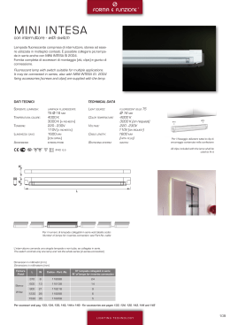
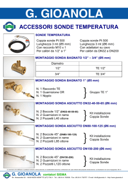
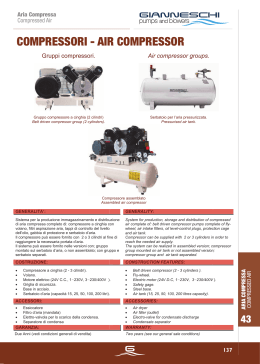
®
GB
DEHUMIDIFIERS
OWNER’S MANUAL
DÉSHUMIDIFICATEURS
FR MANUEL D’UTILISATION
LUFTENTFEUCHTER
DE BEDIENUNGSANLEITUNG
DEUMIDIFICATORI
IT MANUALE OPERATIVO
DESHUMIDIFICADORES
ES MANUAL DE INSTRUCCIONES
LUCHTONTVOCHTIGER
NL GEBRUIKERSHANDLEIDING
MODELS - MODÈLES - MODELLE - MODELLI - MODELOS - MODELLEN :
DH 25, DH 40, DH 55, DH 80
CONTROL BOARD
TABLEAU DE COMMANDE
KONTROLLTAFEL
QUADRO COMANDI
TABLEO DE MANDOS
BEDIENINGSPANEEL
CONTROL BOARD - TABLEAU DE COMMANDE - KONTROLLTAFEL
QUADRO COMANDI - TABLEO DE MANDOS - BEDIENINGSPANEEL
c
e
ON
OFF
a
20%
80%
UR%
50%
d
b
a
Interruttore principale
Interrupterur marche/arrêt
Ein/aus Schalter
Main switch
Interruptor ON/OFF
Aan/uitschakelaar
d
Manopola regolazione dell’umidostato
Commande d’humidistat
Hygrostat Regelknopf
Hygrostat adjusting knob
Regulación humidostato
Hydrostaat regelknop
b
Spia di sicurezza
Lampe témoin securité
Kontrollampe
Control lamp
Testigo de seguridad
Veiligheidscontrolelampje
e
Contaore
Compte-heures
Stundenzähler
Hour-counter
Cuentahoras
Urenteller
c
Spia di segnalazione della vaschetta piena
(Eccetto DH 80)
Lampe témoin - bac récupérateur plein
(Sauf DH 80)
Kontrollampe - Wasserbehälter “voll”
(Mit Ausnahme von DH 80)
Pilot lamp - water container full
(Except DH 80)
Control depósito lleno
(Excepto DH 80)
Controlelampje – waterreservoir vol
(Niet in DH 80)
2
®
CE DECLARATION OF CONFORMITY
DÉCLARATION DE CONFORMITÉ CE
KONFORMITÄTSERKLÄRUNG
DICHIARAZIONE DI CONFORMITÀ CE
DECLARACIÓN DE CONFORMIDAD CE
CE CONFORMITEITSVERKLARING
PRODUCER/PRODUCTER/HERSTELLER/PRODUTTORE/PRODUCTOR/PRODUCENT:
DESA Europe BV
3364 DA Sliedrecht
The Netherlands 3364
Tel. +31-10-4376666
Fax +31-10-4150910
Internet: www.desaeurope.com
e-mail: [email protected]
portable forced air heaters, models:
appareils de chauffage à air forcé, modèles:
Mobile Hochdruck-Heißluftgeneratoren, Modelle:
riscaldatori mobili ad aria forzata, modelli:
calentadores móviles de aire forzata, modelos:
draagbare hoge druk verwarmingstoestellen, modellen:
DH 25, DH 40, DH 55, DH 80
It is hereby declared that these models conform to the essential safety requirements laid down by Machines Directive 89/392, including
the modifications introduced by Directives 91/368, 93/44, 93/68, 98/37 and by directives 89/336, 92/31, 73/23.
All the models listed conform to these requirements.
Nous déclarons que ces modèles sont conformes aux conditions essentielles de qualité indiquées dans la Directive Machines 89/392, y
compris les variantes introduites par les Directives 91/368, 93/44, 93/68, 98/37 et par les Directives 89/336, 92/31, 73/23.
Nous déclarons que tous les modèles listés sont conformes.
Der Hersteller erklärt, dass die angegebenen Modelle den grundlegenden Sicherheitsanforderungen gemäß EG-Maschinenrichtlinie
89/392, einschließlich der mit den Richtlinien 91/368, 93/44, 93/68, 98/37 und von den Richtlinien 89/336, 92/31, 73/23 eingeführten
Änderungen, genügen.
Wir erklären alle aufgelisteten Modelle für konform.
Si dichiara che questi modelli sono conformi ai requisiti essenziali di sicurezza indicati dalla Direttiva Macchine 89/392 comprese le
varianti introdotte con le Direttive 91/368, 93/44, 93/68, 98/37 e dalle Direttive 89/336, 92/31, 73/23.
Dichiariamo conformi tutti i modeli elencati.
Se declara que estos modelos responden a los requisitos fundamentales de seguridad indicados por la Directiva Máquinas 89/392 incluidas las variantes introducidas con las Directivas 91/368, 93/44, 93/68, 98/37 y con las Directivas 89/336, 92/31, 73/23.
Se declaran conformes todos los modelos a continuación.
Bij deze wordt verklaard dat deze modellen conform de veiligheidseisen zijn van de Machine Richtlijnen 89/392, inclusief de veranderingen aangebracht in de Richtlijnen 91/368, 93/44, 93/68, alsook in de Richtlijnen 89/336, 92/31, 73/2.
Alle genoemde modellen zijn conform deze vereisten.
Company
Name
Position
DESA Europe B.V.
Augusto Millan
Technical Manager
Date and place
Signature
Sliedrecht, 15-04-2003
4
DESCRIPTION
INSTRUCTIONS FOR USE
DESCRIPTION
DH dehumidifiers have been designed for use in places which have
to be dried quickly or where an uncontrolled rise in levels of relative
humidity cannot be permitted.
DH dehumidifiers reduce the relative water vapour condensation
level in the air.
As you can see in figure 1, each unit has a refrigeration circuit and
a fan.The air which is drawn in by the fan (3) passes through the filter (5) and strikes the cold walls of the evaporator (6) where it cools
to a temperature which is slightly below condensation point. Some
of the vapour condenses and is collected in the water tank (9). Then
the air passes through the condenser (4) and is heated to a temperature which is slightly higher than room temperature.
4
WARNING: Cloths or coverings of any kind
must not be placed on the dehumidifier when it
is working.
INSTRUCTIONS FOR USE
5
6
2
7
8
9
Fig. 1 How the unit works:1. Air-tight compressor. 2. Control
device 3. Helical fan 4. Condenser 5. Air filter 6. Evaporator 7. Tube
fitting 8. Float 9. Water tank (Except DH 80).
Best results are obtained at relative humidity levels of between 40%
and 100% and at temperatures that range from 3° to 40°.
A humidistat automatically controls the unit, turning it on and off
when the desired level has been attained.The electronic control
device (2) automatically starts and stops the defrosting process in
accordance with the workings of the unit. In case of overheating due
to malfunction or if the unit has been used in a place where the temperature exceeds the maximum permitted limit of 40°C, the control
device automatically blocks the unit, the fan and compressor stop
and the control lamp (b) lights up.
WARNING: If room temperature is lower than
the minimum permitted value (3°C) the dehumidifier doesn’t work and the control lamp (b)
flashes.
GB
The dehumidifier should preferably be placed in the middle of the
space where it will operate so that the intake and expulsion of air will
not be hindered. It should be at least 20-30 cm
from any wall. It should not be placed next to sources of heat such
as radiators, stoves or other heat outlets. It should not be placed
near doors or openings. When the dehumidifier is working all doors
and windows must be shut.
If necessary, the water tank can be removed and the water drained
off directly by attaching a rubber tube to the tube fitting (7).
3
1
WARNING: The mains supply to the heater
(230V, monophase, 50 Hz) must be earthed and
have a magneto-thermal switch with differential.
TURNING ON
WARNING: The dehumidifier must be used,
stocked and, for DH 25, transported in a vertical
position. Should this not be the case, the
machine will not function properly.
To turn on the unit proceed as follows:
• Turn the hydrostat adjusting knob clockwise to 20%.
• Turn ON the green switch (a) -position “1”. The fan and compressor start and the switch lights up.
• Turn the hydrostat adjusting knob (d) anti-clockwise to the desired
relative humidity level.
WARNING: The dehumidifier is provided with
an automatic security device which starts the
compressor just 1 minute after the switch (a) is
on.
TURNING OFF
Turn OFF the green switch (a)-position “0”.
WARNING: If room temperature is lower than
the minimum permitted value (3°C) the dehumidifier doesn’t work and the control lamp (b)
flashes.
THE WATER TANK (EXCEPT DH 80)
When the water tank is full the unit stops immediately and the pilot
lamp (c) comes on. The tank must be emptied before the unit can
start working again.
MAINTENANCE
TRANSPORT AND MOVEMENT
DISMANTLING AND DISPOSAL
5
WARNING: Before taking out the water tank,
turn OFF the main switch and take out the plug.
WARNING: After emptying , put the water tank
very carefully back in its bay so as not to damage or interfere with the switch which is connected to the float.
MAINTENANCE
WARNING: Before any maintenance operation turn OFF the main switch and take out the
plug.
To work efficiently the air filter and the internal parts of the humidifier must be cleaned periodically. To clean the air filter apply compressed air or wash with tepid soapy water.
To gain access to the internal parts unscrew the external casing
panels. The internal parts must be cleaned with an aspirator. Take
special care when cleaning the condenser’s and evaporator’s ribbed
batteries and the fan blades.
TRANSPORT AND MOVEMENT
WARNING: Before moving a unit turn OFF the
main switch and take out the plug.
The dehumidifier must not be transported in a horizontal position.
Having wound up the electrical cable, wheel the unit. must be tilted
as illustrated in Fig. 2.
Fig. 2
To move the unit up or down a stairs or steep incline proceed as
illustrated in Fig. 3
Fig. 3
DISMANTLING
AND DISPOSAL
There is a pressurized refrigerant, R407C, in the refrigeration circuit
and oil in the compressor. For this reason, when a unit has come to
the end of its working life, it must not be dumped. It must be distmantled and the various parts can be recycled and/or scrapped.
Refrigerants cannot be dumped. In order to extract R407C you
need:
1. A pliers like the one in Fig. 4.
WARNING: The following operations must be
carried out by qualified personnel.
2. Motorcondenser
3. Pressurized vessel
Fig. 4
Proceed as follows:
• Connect the pressurized vessel to the motorcondenser, and the
motorcondenser to the pliers.
• Punch a hole in the compressor’s exit tube and leave the pliers in
position.
• Open both motorcondenser taps, turn it on and empty the refrigeration circuit.
• Stop the motorcondenser and close both taps. Then close the tap
on the pressurised vessel.
• Remove the pliers.
• If the pressurized vessel is full it should be given to a company that
specializes in the disposal of waste fluids.
The welded joints on the compressor’s entry and exit tubes should
be elimimated and lock bolts removed. Then drill a hole in the underside of the chassis, and pour the mineral oil into a vessel which
should be delivered to a company that specializes in the recycling
and disposal of oil.
The remaining metal parts which contain copper, aluminium and
steel can be recycled or scrapped.
GB
6
OBSERVED FAULT, POSSIBLE CAUSES AND REMEDIES
OBSERVED FAULT, POSSIBLE CAUSES AND REMEDIES
PROBLEM
CAUSE
1 No electricity
REMEDY
1a Check that the the switch is working and that it
is ON
1b Check mains caracteristics (220V, 1 ~, 50 Hz)
The unit won't start
The ventilator and compressor are
working but neither water nor ice form on
the walls of the evaporator
The unit stops and the pilot lamp (c)
comes on
The unit stops and the control lamp (b)
comes on (the condenser's ribbed
battery has over heated)
The unit stops and the control lamp (b)
flashes
GB
2 Humidistat not set correctly
2 Set the humidistat at a relative humidity level
which is lower than the room humidity level
3 Water tank full (pilot light "c"on)
3 Empty the water tank.
1 Air flow not sufficient
1a Check that nothing is blocking intake and
expulsion of air
1b Check that there aren't any deposits or
incrustation on the filter or on the ribbed batteries
of the condenser or of the evaporator
2 Room temperature and relative humidity
level too low.
2 Check that the temperature is between 0° and
40° and that relative humidity is between 40%
3 Refrigeration circuit not working correctly
3 Call an Authorised Service Technician
1 Water tank full
1 Empty the water tank
1 Air flow obstructed
1 Remove obstacles to air flow and start unit
again
2 Air temperature above 40 °C
2 Only use unit when temperature drops below
40°C
3 Fan motor broken
3 Call an Authorized Service Technician
4 Refrigeration circuit not working correctly
4 Call an Authorized Service Technician
1 Temperature lower than 3°C
1 Move the dehumidifier in a place where
temperature is 3°C
24
WIRING DIAGRAM
SCHEMA ELECTRIQUE
SCHALTSCHEMA
SCHEMA ELETTRICO
ESQUAMA ELÉCTRICO
ELEKTRISCH SCHEMA
WIRING DIAGRAM - SCHEMA ELECTRIQUE - SCHALTSCHEMA
SCHEMA ELETTRICO - ESQUAMA ELÉCTRICO - ELEKTRISCH SCHEMA
DH 25; DH 40; DH 55
LEGENDA
LEGENDA
MV
MOTORE VENTILATORE
MOTEUR DU VENTILATEUR
VENTILATOR MOTOR
FAN MOTOR
MOTOR VENTILADOR
VENTILATORMOTOR
IG
INTERRUTTORE DI ACCENSIONE
INTERRUPTEUR MARSCHE – ARRET
EIN – AUS SCHALTER
ON – OFF SWITCH
INTERRUPTOR ON-OFF
AAN/UITSCHAKELAAR
S1
SONDA SBRINAMENTO
SONDE DE DEGIVRAGE
ABTAUEN SONDE
DE – ICING PROBE
SONDA DECONGELACION
ONTDOOIINGSSONDE
SA
SPIA DI RIEMPIMENTO VASCHETT
LAMPE TEMOIN DE REMPLISSAGE DU BAC AU EAU
ANFÜLLSIGNAL DER WASSERWANNE
WATER TANK FULL LEVEL LIGHT
TESTIGO DE DEPOSITO LLENO
CONTROLELAMPJE WATERBAK VOL
S2
SONDA SOVRARISCALDAMENTO
SONDE DE SURCHAUFFE’
ÜBERHITZUNG SONDE
OVETHEA PROBE
SONDA DE SOBRECALENTAMIENTO
OVERVERHITTINGSSONDE
SB
SPIA DI BLOCCO
LAMPE TEMOIN ARRET
“AUS” KONTROLLLAMPE
STOP CONTROLL LAMP
TESTIGO DE BLOQUEO
“UIT” CONTROLELAMPJE
S3
SONDA AMBIENTE
SONDE
AMBIANTEFÜHLER FÜR RAUMTEMPERATUR
AMBIENT PROBE
SONDA AMBIENTE
SONDE VOOR OMGEVINGSTEMPERATUUR
UM
UMIDOSTATO
HYGROSTAT
HYGROSTAT
HYGROSTAT
HUMIDOSTATO
HYDROSTAAT
CP
COMPRESSORE
COMPRESSEUR
KOMPRESSOR
COMPRESSOR
COMPRESOR
COMPRESSOR
ST
SPIA TENSIONE
LAMPE TEMOIN DE TENSION
SPANNUNGSKONTROLLAMPE
VOLTAGE LIGHT
TESTIGO DE TENSION
VOLTAGELAMPJE
CO
CONDENSATORE
CONDENSATEUR
KONDENSATOR
CONDENSER
CONDENSADOR
CONDENSATOR
EV
ELETTROVALVOLA
ELECTROVANNE
MAGNETVENTIL
SOLENOID VALVE
ELECTROVALVULA
ELEKTROMAGNEETVENTIEL
FU
FUSIBILE (500 mA)
FUSIBLE (500 mA)
SICHERUNG (500 mA)
FUSE (500 mA)
FUSIBLE (500 mA)
ZEKERING ( 500 MA)
AP
APPARECCHIATURA DI CONTROLLO
COFFRET DE CONTROLLE
STEÜRGERÄT
CONTROL BOX
APARATO DE CONTROL
CONTROLEAPPARAAT
IA
INTERRUTTORE DI RIEMPIMENTO VASCHETTA ACQUA
INTERRUPTEUR DE TROP PLEIN
WASSERBEHÃLTERSCHALTER
FLOAT SWITCH
FLOTADOR
SCHAKELAAR VLOTTER
TC
TERMOSTATO COMPRESSORE
THERMOSTAT DE COMPRESSEUR
KOMPRESSOR THERMOSTAT
COMPRESSOR THERMOSTAT
TERMOSTATO COMPRESOR
COMPRESSORTHERMOSTAAT
TI
CONTAORE
COMPTE-HEURES
STUNDENZÄHLER
HOUR-COUNTER
CUENTAHORAS
URENTELLER
RC
RELE’ COMPRESSORE
RALAIS DU COMPRESSEUR
KOMPRESSOR THERMOSTAT
COMPRESSOR THERMOSTAT
RELE´ COMPRESOR
COMPRESSORTHERMOSTAAT
25
26
WIRING DIAGRAM
SCHEMA ELECTRIQUE
SCHALTSCHEMA
SCHEMA ELETTRICO
ESQUAMA ELÉCTRICO
WIRING DIAGRAM - SCHEMA ELECTRIQUE - SCHALTSCHEMA
SCHEMA ELETTRICO - ESQUAMA ELÉCTRICO - ELEKTRISCH SCHEMA
DH 80
LEGENDA
LEGENDA
MV
S1
S2
S3
CP
CO
FU
TI
MOTORE VENTILATORE
MOTEUR DU VENTILATEUR
VENTILATOR MOTOR
FAN MOTOR
MOTOR VENTILADOR
VENTILATORMOTOR
SONDA SBRINAMENTO
SONDE DE DEGIVRAGE
ABTAUEN SONDE
DE – ICING PROBE
SONDA DECONGELACION
ONTDOOIINGSSONDE
SONDA SOVRARISCALDAMENTO
SONDE DE SURCHAUFFE’
ÜBERHITZUNG SONDE
OVETHEA PROBE
SONDA DE SOBRECALENTAMIENTO
OVERVERHITTINGSSONDE
SONDA AMBIENTE
SONDE
AMBIANTEFÜHLER FÜR RAUMTEMPERATUR
AMBIENT PROBE
SONDA AMBIENTE
SONDE VOOR OMGEVINGSTEMPERATUUR
COMPRESSORE
COMPRESSEUR
KOMPRESSOR
COMPRESSOR
COMPRESOR
COMPRESSOR
CONDENSATORE
CONDENSATEUR
KONDENSATOR
CONDENSER
CONDENSADOR
CONDENSATOR
FUSIBILE (500 mA)
FUSIBLE (500 mA)
SICHERUNG (500 mA)
FUSE (500 mA)
FUSIBLE (500 mA)
ZEKERING ( 500 MA)
CONTAORE
COMPTE-HEURES
STUNDENZÄHLER
HOUR-COUNTER
CUENTAHORAS
URENTELLER
IG
INTERRUTTORE DI ACCENSIONE
INTERRUPTEUR MARSCHE – ARRET
EIN – AUS SCHALTER
ON – OFF SWITCH
INTERRUPTOR ON-OFF
AAN/UITSCHAKELAAR
SB
SPIA DI BLOCCO
LAMPE TEMOIN ARRET
“AUS” KONTROLLLAMPE
STOP CONTROLL LAMP
TESTIGO DE BLOQUEO
“UIT” CONTROLELAMPJE
UM
UMIDOSTATO
HYGROSTAT
HYGROSTAT
HYGROSTAT
HUMIDOSTATO
HYDROSTAAT
ST
SPIA TENSIONE
LAMPE TEMOIN DE TENSION
SPANNUNGSKONTROLLAMPE
VOLTAGE LIGHT
TESTIGO DE TENSION
VOLTAGELAMPJE
EV
ELETTROVALVOLA
ELECTROVANNE
MAGNETVENTIL
SOLENOID VALVE
ELECTROVALVULA
ELEKTROMAGNEETVENTIEL
AP
APPARECCHIATURA DI CONTROLLO
COFFRET DE CONTROLLE
STEÜRGERÄT
CONTROL BOX
APARATO DE CONTROL
CONTROLEAPPARAAT
TC
TERMOSTATO COMPRESSORE
THERMOSTAT DE COMPRESSEUR
KOMPRESSOR THERMOSTAT
COMPRESSOR THERMOSTAT
TERMOSTATO COMPRESOR
COMPRESSORTHERMOSTAAT
27
TECHNICAL SPECIFICATIONS
CARACTERISTIQUES TECHNICAL
TECHNISCHE DATEN
CARATTERISTICHE TECNICHE
CARACTERISTICAS TECNICAS
TECHNISCHE GEGEVENS
28
TECHNICAL SPECIFICATIONS - CARACTERISTIQUES TECHNICAL - TECHNISCHE DATEN
CARATTERISTICHE TECNICHE - CARACTERISTICAS TECNICAS - TECHNISCHE GEGEVENS
DH 25
DH 40
DH 55
DH 80
Umidità relativa1 - Humidité relative1 -Relative Luftfeuchtigkeit1
Relative humidity1 - Humedad relativa1
[%]
40 - 100
[°C]
3 - 40
Relatieve luchtvochtigheid1
Temperatura1 - Température1 - Temperatur1
Temperature1 - Temperatura1 - Temperatuur1
Portata d' aria - Débit d' air - Luftdurchsatz
Air flow - Capacidad aire - Luchtaan- en afvoer
[m3/h]
250
400
650
900
[l/24h]
22
40
52
80
525
1600
Capacità di deumidificazione2 - Capacité de déshumidification2
Entfeuchtungsleistung2 - Water extraction2
Capacidad de deshumidificación2-Ontvochtigingscapaciteit2
Tipo di refrigerante - Type de réfrigérant - Kühlmittel
Refrigerant - Tipo de refrigerante - Koelvloeistoftype
R407C
Massa di refrigerante - Quantité de réfrigérant
Kühlmittel Menge - Refrigerant quantity
Cantitad de refrigerante - Hoeveelheid koelvloeistof
Alimentazione elettrica
Alimentatione électrique
Netzanscluss
Power supply
Alimentación eléctrica
Netspanning
[g]
Fase - Phase - Phase - Phase
Fase - Fase
Tensione - Tension Spannung
Voltage - Tensión - Spanning
Frequenza - Fréquence - Frequenz
Frequency - Frecuencia - Frequentie
2
Potenza elettrica assorbita - Puissance absorbé
300
425
1
[V]
230
[Hz]
50
2
Leistungsaufnahme2 - Power consumption2 - Potencia eléctrica
[W]
550
800
1000
1350
[dBA]
59
60,8
65,1
63,6
[l]
5
11
11
-
[mm]
540 x 585 x
775
650 x 615 x
958
650 x 615 x
958
761 x 776 x
1048
[kg]
39
49
52
76
absorbida2 - Energieverbruik2
Livello sonoro, SPL - Niveau sonore, SPL
Geraüschspegel, SPL - Noise level, SPL
Nivel sonoro - Geluidsniveau, SPL
Capacità serbatoio - Capacité réservoir - Tankinhalt
Tank capacity - Capacidad depósito - Capaciteit watertank
Dimensioni, L x P x A - Dimensions, L x P x H
Masse, H x B x T - Dimensions, L x W x H
Dimensiones, L x P x A - Afmeting, B x D x H
Peso - Poids - Gewicht
Weight - Peso - Gewicht
1 : Intervallo valori di funzionamento / Plage de fonctionnement / Arbeitsbereich / Working range/Intervalo valores de
funcionamiento / Functioneringsbereik
2
: T= 30 °C; UR= 80%.
DESA Europe BV
3364 DA Sliedrecht
The Netherlands 3364
Tel. +31-10-4376666 - Fax +31-10-4150910
Internet: www.desaeurope.com - e-mail: [email protected]
Scaricare