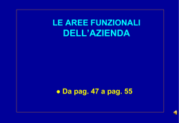
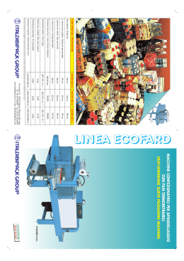
CONFEZIONATRICI SOTTOVUOTO A CAMPANA
BEL VACUUM PACKING APPLIANCES
MODELLO / MODEL
0
SV - 410
SV – 500
SV - 440
SV – 550
SV - 600
SV – 600/500
SV – UNICA
SV – 900/500
DVA – 32
DVA – 41
DVA – 50
DVA – 250
DVA – 255
DVA – 60
DVA – 256
DVA – 295
MADE IN ITALY
MANUALE D’ISTRUZIONI / INSTRUCTION MANUAL
Ver. 6 Rev. 4 09/13
E’ vietato la riproduzione. Tutti i diritti sono riservati. Nessuna parte del presente manuale può essere prodotta o diffusa con
qualsiasi mezzo, fotocopie, microfilm o altro, senza il consenso scritto della WAAGE s.r.l.
Partial or total reproduction prohibited. All rights reserved. No part of this manual can be produced or propagated by any means
photocopies, microfilm or other without the written consent of WAAGE s.r.l.
2
Manuale d’istruzioni / Instruction manual
Rev. 7 04/09/2013
INDICAZIONI VELOCI DI PROGRAMMAZIONE
PANNELLO DIGITALE " DVA ...."
SELEZIONA PROGRAMMA
Le confezionatrici sottovuoto serie DVA sono state studiate per gli operatori che hanno l’ esigenza di confezionare vari tipi di alimenti
con differenti buste e tempi di confezionamento.
Per selezionare i programmi digitare i tasti [ + ] e [ - ]
PROGRAMMAZIONE ( è possibile modificare e impostare 20 programmi in memoria )
Digitando il tasto [ PRG ], sul LCD comincia a lampeggiare la percentuale di vuoto che si vuole ottenere nella vasca,
per aumentare o diminuire la percentuale di vuoto selezionare i tasto [ + ] e [ - ].
Digitando il tasto [ SEL ] seleziona la riga successiva. " EXTRA VUOTO - GAS (dove previsto) - SALDATURA "
Dopo aver impostato il programma e i tempi di confezionamento digitare il tasto [ PRG ] per uscire dalla programmazione e iniziare a
lavorare.
VERSIONE CON STAMPANTE INTEGRATA
La stampa dello scontrino avviene automaticamente ad ogni fine ciclo di lavoro.
sullo scontrino automaticamente la macchina stampa il giorno di confezionamento e il numero progressivo dello scontrino.
LOTTO: per inserire il codice lotto numerico digitare il tasto [ LOTTO ] compare la scritta lotto 000000
inserire con i tasti [ + ] e [ - ] il numero da inserire
per andare alla posizione successiva digitare il tasto [ SEL ]
per uscire dalla programmazione digitare il tasto [ LOTTO ]
PROGRAMM PANNEL DVA
SELECT PROGRAM
The packaging vacuum machines series DVA are adapted for users who need to package several type of aliments with different kind of
bags and packaging time.
To select the programs digit the following keys [ + ] and [ - ]
PROGRAMING ( it is possibile to change and set up 20 programs in the storage )
Selecting key [ PRG ], on the LCD it begins to flash the vacuum percentage wanted within the chamber,
to incresce and diminish the vacuum percentage selct keys [ + ] and [ - ].
Selecting key [ SEL ] it selects the following row.
After settino-up the program and the packaging time digit key [ PRG ] to exit programing and begin working.
3
Manuale d’istruzioni / Instruction manual
Rev. 7 04/09/2013
INFORMAZIONI GENERALI
INTRODUZIONE
Pag. 4
IDENTIFICAZIONE DEL COSTRUTTORE
Pag. 4
IDENTIFICAZIONE DELL’ APPARECCHIO
Pag. 4
NORME GENERALI DI SICUREZZA E PREVENZIONE
Pag. 4
GARANZIA
Pag. 4
INFORMAZIONI TECNICHE
DATI TECNICI
Pag. 5
SIMBOLI
Pag. 5
CAMPO D’IMPIEGO
Pag. 5
MOVIMENTO E DISIMBALLO
Pag. 5
ISTALLAZIONE
DESCRIZIONE DEL SOTTOVUOTO
Pag. 5
TENSIONE DI ALIMENTAZIONE
Pag. 6
NORME GENERALI D’IMPIEGO
Pag. 6
PANNELLO DI CONTROLLO
Pag. 7
USO DELL’ APPARECCHIO
FUNZIONE VUOTO
Pag. 8
FUNZIONE GAS
Pag. 8
FUNZIONE SALDATURA
Pag. 8
USO DELL’APPARECCHIO
Pag. 8
FUNZIONE E PROGRAMMAZIONE
Pag. 8
ATTIVAZIONE / DISATTIVAZIONE FUNZIONE GAS
Pag. 8
ATTIVAZIONE / DISATTIVAZIONE BARRE SALDANTI
Pag. 8
MANUTENZIONE
SOSTITUZIONE DEL TEFLON - RESISTENZA BARRA SALDANTE
Pag. 9
SOSTITUZIONE DELL’OLIO POMPA
Pag. 9
SOSTITUZIONE GUARNIZIONE COPERCHIO
Pag. 10
SMALTIMENTO DELLA CONFEZIONATRICE SOTTOVUOTO
Pag. 10
GIUDA ALLA RISOLUZIONE DEI PROBLEMI
Pag. 11
SCHEDA DI MANUTENZIONE
Pag. 21
4
Manuale d’istruzioni / Instruction manual
Rev. 7 04/09/2013
INTRODUZIONE
Il manuale di istruzioni fornisce tutte le informazioni necessarie per l’impiego, la conservazione e lo smaltimento dell’apparecchio, è da
considerarsi parte integrante dell’apparecchio e come tale deve essere conservato e custodito per tutta la durata dello stesso.
L’acquirente ha l’obbligo di leggere attentamente il presente manuale per l’uso e la manutenzione del sottovuoto.
Seguire scrupolosamente tutti i consigli e le direttive presenti in questo manuale, in quanto il funzionamento e la conservazione della,
dipendono del corretto uso delle applicazioni dei suggerimenti di seguito descritti.
La casa costruttrice si declina da ogni responsabilità per danni a persone, cose o animali, derivante dalla mancata osservazione delle
prescrizioni riportate nel presente manuale, dalle avvertenze per la sicurezza, dalle modifiche apportate sull’apparecchio senza
autorizzazione, dalle manomissioni e dell’impiego di parti di ricambio non originali.
IDENTIFICAZIONE DELL’ APPARECCHIO
L’apparecchio è identificato attraverso una targa posta sul lato posteriore, sulla quale si possono rilevare le seguenti informazioni:
Dati generali:
• Nome e recapito del costruttore:
• Modello, Matricola e marcatura CE
• Tensione, frequenza e potenza nominali
ATTENZIONE! E’ assolutamente vietato manomettere, o alterare in qualsiasi modo o asportare la
targa di identificazione dell’apparecchio. Non coprirla con nastri adesivi o altro in quanto deve
risultare sempre ben visibile.
NORME GENERALI DI SICUREZZA E PREVENZIONE
►
Non toccare l’apparecchio con le mani bagnate o umide.
Non utilizzare l’apparecchio a piedi scalzi.
In caso di guasti o cattivo funzionamento, spegnere l’apparecchio e scollegarlo dalla rete
Non lasciare l’apparecchio esposto ad agenti atmosferici.
Non immergerlo in acqua.
Non affidarne l’uso ai bambini o a persone non qualificate.
Staccare la spina prima di effettuare qualsiasi operazione diversa dal confezionamento.
Quando l’apparecchio non viene utilizzato, spegnere l’interruttore e disinserire la spina di rete.
Non tirare il cavo di alimentazione per staccare la spina della presa elettrica.
Verificare periodicamente il livello dell’olio motore, in caso di sostituzione rivolgersi presso un Centro Tecnico di
Assistenza Autorizzato.
In caso di riparazioni o sostituzione dei componenti, utilizzare ricambi originali.
In caso di incompatibilità tra la spina di alimentazione di fabbrica e la vostra, fatela sostituire da un Centro Tecnico
di Assistenza.
Si sconsiglia l’uso di adattatori non omologati e/o prolunghe.
GARANZIA
Tutti i prodotti vengono sottoposti a severi controlli qualitativi funzionali prima dell’istallazione da parte della casa costruttrice e sono garantiti
da tutti i difetti di fabbricazione.
La garanzia ha durata di 12 mesi dalla data di vendita riportata sul documento di consegna.
Oltre allo scadere del normale periodo di copertura, la garanzia si riterrà immediatamente decaduta nei seguenti casi:
Targa di identificazione dell’apparecchio manomessa.
Modifiche sull’apparecchio senza la preventiva autorizzazione scritta del costruttore.
Mancato rispetto delle indicazioni riportate nel presente manuale.
Uso dell’apparecchio diverso da quello riportato nel presente manuale.
Danni subiti dall’apparecchio derivati da fattori esterni.
Operazioni di conduzione, riparazione e manutenzione svolte da persone non specializzate.
MOVIMENTO E DISIMBALLO
Al ricevimento dell’imballo il cliente è tenuto a verificare l’integrità, comunicando tempestivamente al corriere o all’addetto al trasporto,
eventuali anomalie mancanze o danni evidenti.
Dopo aver tolto l’imballo, assicurarsi dell’integrità dell’apparecchio, in caso di dubbi, non utilizzatelo e rivolgetevi al rivenditore.
Gli elementi dell’ imballo non devono essere lasciati alla portata dei bambini o disperderli nell’ambiente.
CAMPO D’ IMPIEGO
La confezionatrice sottovuoto a campana sono stata progettate e studiate per effettuare il vuoto in sacchetti e contenitori rigidi speciali.
Non è consentito l’uso dell’apparecchio con modalità o per finalità diverse da quelle indicate dal costruttore nel presente manuale.
Manuale d’istruzioni / Instruction manual
5
Rev. 7 04/09/2013
DATI TECNICI
Confezionatrici sottovuoto serie SV
CARATTERISTICHE
MODELLO
SV - 410
MODELLO
SV – 500
MODELLO
SV – 520
MODELLO
SV – 550
MODELLO
SV – 600
MODELLO
SV – 600/500
MODELLO
UNICA
MODELLO
SV – 900/500
Dimensioni
d’ingombro
515x596x370
590x670x350
590x670x350
710x670x910
710x670x910
710x670x910
710x670x910
1060X687X91
0
Dimensioni camera
417x450x180
515x550x200
515x550x200
610x550x200
610x550x200
610x550x200
610x550x200
925X547X200
Pompa per vuoto
Q= 25 mc/h
Q= 25 mc/h
Q= 25 mc/h
Q= 40-60mc/h
Q= 40-60 mc/h
Q= 40-60 mc/h
Q= 40 mc/h
Q= 60 mc/h
Q= 105 mc/h
Barra saldante
N°1 400 mm
N°1 500 mm
N°2 500 mm
N°2 550 mm
N°1 600 mm
N°1 600 mm
N°1 500
N°1 600 mm
N° 2 500 mm
N°1 900 mm
N° 1 500 mm
Gas inerte
2 ugelli
2 ugelli
4 ugelli
4 ugelli
3 ugelli
5 ugelli
7 ugelli
5 ugelli
Ciclo di lavoro
20 PRG
Automatico
Automatico
Automatico
Automatico
Automatico
Automatico
Automatico
Struttura
Acciaio inox
Acciaio inox
Acciaio inox
Acciaio inox
Acciaio inox
Acciaio inox
Acciaio inox
Acciaio inox
Alimentazione
220 v / 50 Hz
220 v / 50 Hz
220 v / 50 Hz
380 v / 50 Hz
380 v / 50 Hz
380 v / 50 Hz
380 v / 50 Hz
380 v / 50 Hz
Peso
75 Kg
75 Kg
75 Kg
150 Kg
150 Kg
150 Kg
150 Kg
250 Kg
Confezionatrici sottovuoto serie DVA
CARATTERISTICHE
MODELLO
DVA - 32
MODELLO
DVA - 41
MODELLO
DVA - 50
MODELLO
DVA - 520
MODELLO
DVA - 255
MODELLO
DVA - 60
MODELLO
DVA -265
MODELLO
DVA - 295
Dimensioni
d’ingombro
390x596x320
515x596x370
590x670x350
590x670x350
710x670x910
710x670x910
710x670x910
1060X687X91
0
Dimensioni camera
330x400x180
417x450x180
515x550x200
515x550x200
610x550x200
610x550x200
610x550x200
925X547X200
Pompa per vuoto
Q= 8 mc/h
Q= 25 mc/h
Q= 25 mc/h
Q= 25 mc/h
Q= 60mc/h
Q= 60 mc/h
Q= 60 mc/h
Q= 105 mc/h
Barra saldante
N°1 320 mm
N°1 400 mm
N°1 500 mm
N°2 500 mm
N°2 550 mm
N°1 600 mm
Gas inerte
1 ugelli
2 ugelli
4 ugelli
4 ugelli
4 ugelli
3 ugelli
5 ugelli
5 ugelli
Ciclo di lavoro
20 PRG
20 PRG
20 PRG
20 PRG
20 PRG
20 PRG
20 PRG
20 PRG
Struttura
Acciaio inox
Acciaio inox
Acciaio inox
Acciaio inox
Acciaio inox
Acciaio inox
Acciaio inox
Acciaio inox
Alimentazione
220 v / 50 Hz
220 v / 50 Hz
220 v / 50 Hz
220 v / 50 Hz
380 v / 50 Hz
380 v / 50 Hz
380 v / 50 Hz
380 v / 50 Hz
Peso
50 Kg
75 Kg
75 Kg
75 Kg
150 Kg
150 Kg
150 Kg
250 Kg
SIMBOLI
.
N°1 600
N°1 500
N°1 900 mm
N° 1 500 mm
6
Manuale d’istruzioni / Instruction manual
Rev. 7 04/09/2013
DESCRIZIONE DEL SOTTOVUOTO
Le confezionatrici sottovuoto a campana sono indicate per il confezionamento di prodotti asciutti e/o stagionati e di prodotti contenenti
umidità, grazie al principio di funzionamento basato sulla creazione del vuoto all’interno di una camera (o vasca) all’interno della quale è
collocato il prodotto.
Il vuoto massimo viene raggiunto in un tempo che dipende dal volume d’aria che viene aspirato, pertanto è consigliabile utilizzare sempre il
numero massimo di ripiani compatibilmente con le dimensioni del prodotto da confezionare, questo Vi permetterà di abbreviare i tempi di
realizzazione del vuoto.
Le macchine sottovuoto sono realizzate dalle seguenti parti:
Vasca in acciaio inox (o camera vuoto), all’interno della quale viene realizzato il vuoto, ed eseguite la sigillatura delle buste
per mezzo della barre saldanti.
Cofano in acciaio inox.
Pompa per il vuoto ad alta prestazione a ricircolo, dotato di un vetrino spia di livello olio.
Impianto di aspirazione dell’ aria formata da raccordi e tubi che collega la camera per il vuoto con la pompa.
Impianto elettrico comprende scheda elettronica di potenza con porta fusibili, contattori/termiche e connessioni.
Cruscotto in plastica sulla quale sono collocati il pannello comandi e interruttore generale.
TENSIONE DI ALIMENTAZIONE 230 V ( MONOFASE )
Per l’allacciamento elettrico alla rete di alimentazione , gli apparecchi sono muniti di una spina standard CEE 2P+T/16 A. Prima di eseguire
l’allacciamento assicurarsi che l’impianto elettrico sia compatibile con l’alimentazione della macchina.
PERICOLO ELETTRICO! Prima di eseguire l’allacciamento assicurarsi sempre che
le caratteristiche elettriche dell’impianto generale del locale siano idonee.
TENSIONE DI ALIMENTAZIONE 400 V ( TRIFASE )
Per l’allacciamento elettrico alla rete di alimentazione, gli apparecchi sono muniti di una spina CEE 3P+T/16 A. Prima di eseguire
l’allacciamento assicurarsi che l’impianto elettrico sia idoneo e controllare il senso di rotazione della pompa.
CONTROLLO DEL SENSO DI ROTAZIONE DELLA POMPA:
PERICOLO ELETTRICO! Prima di eseguire l’allacciamento assicurarsi sempre che
le caratteristiche elettriche dell’impianto generale del locale siano idonee e controllare
il senso di rotazione della pompa.
ATTENZIONE! La seguente operazione di scambio delle fasi deve essere effettuata da
personale tecnico qualificato – specializzato.
Procedura:
Accertarsi preventivamente che la tensione indicata sulla targhetta di identificazione della macchina sia la stessa della Vs. rete.
Inserire la spina nella presa dell’apparecchio spento.
Controllare il corretto livello dell’olio della pompa visibile nel vetrino spia della pompa, in caso di livello insufficiente
Regolare il parametro VUOTO a 25 secondi .
Alzare il coperchio in plexiglass abbassando il gancio ferma coperchio.
Accendere l’apparecchio tramite l’interruttore generale.
Chiudere il coperchio e la macchina si avvia automaticamente. Con il senso di rotazione della pompa corretto, il coperchio resta
abbassato, al contrario, se il senso di rotazione non è corretto, il coperchio si risolleva in quanto l’aria viene soffiata anzichè aspirata
all’interno della camera. In questo caso, spegnere immediatamente l’apparecchio e procedere all’inversione delle fasi di alimentazione.
NORME GENERALI D’IMPIEGO
Accertarsi preventivamente che la tensione indicata sulla targhetta di identificazione della macchina sia la stessa della Vostra rete.
Inserire e disinserire la spina nella presa di corrente sempre ad apparecchio spento;
Posizionare la macchina su un solido piano di lavoro orizzontale e in modo che sia accessibile da tutti i lati.
Al fine di evitare un aumento della densità dell’olio, la temperatura ambientale non dovrebbe scendere sotto i 10°.
l’olio della pompa va controllato periodicamente attraverso il vetrino spia posto sul pannello posteriore della macchina. Il
livello dell’olio deve essere compreso tra il il livello minimo e massimo.
L’olio della pompa deve essere sostituito ogni 500 ore di lavoro.
Non toccare le barre saldanti dopo aver effettuato la saldatura della busta.
Non rimuovere per nessun motivo il teflon di copertura posto sulla barra saldante.
Non utilizzare coltelli o altri utensili affilati per l’eliminazione di eventuali residui sulla barra saldante: attendere sempre che
si raffreddi prima di intervenire .
Negli apparecchi provvisti di opzione gas , in nessun caso è permesso l’ utilizzo di miscele o GAS contenenti ossigeno in una
percentuale superiore al 21 %, a causa del rischio di esplosione.
Procedere all’immediato arresto della macchina in caso di fughe di gas causate da raccordi difettosi o ossidati oppure da tubazioni
lesionate. Contattate immediatamente il vostro servizio assistenza più vicino per la sostituzione delle parti danneggiate.
Pulire accuratamente la macchina dopo l’utilizzo; il coperchio in plexiglass deve essere pulito esclusivamente con un panno umido
d’acqua e mai con detergenti o solventi. Per le parti in acciaio inox, utilizzare i prodotti adatti disponibili in commercio.
La sicurezza elettrica di questo apparecchio è assicurata solo se è collegato correttamente ad un impianto di messa a terra efficiente,
come previsto dalle vigenti norme di sicurezza. Il costruttore declina ogni responsabilità per eventuali danni causati dalla mancanza di
messa a terra dell’ impianto.
Manuale d’istruzioni / Instruction manual
7
Rev. 7 04/09/2013
PANNELLO DI CONTROLLO SERIE SV ANALOGICO fig.1
8
6
9 10
10
10
7.
abilita e disabilita la saldatura
DX e SX
La funzione abilita e disabilita le
barre saldanti è utile per i cicli di
lavoro dove occorre utilizzare una
sola barra saldante, se nel ciclo di
lavoro utilizziamo l’ atm, ed
escludiamo la barra saldante è
automatico che viene interrotto il
passaggio del dell’ atm negli ugelli
posizionati vicino la barra saldate
disabilitata.
1
2
3
4
7
5
Questa funzione è installata
SV – 440
SV – 550
SV – 600/500
SV – UNICA
SV – 900/500
7
1. Interruttore generale 2. Vacuometro 3. Temporizzatore vuoto 4. Temporizzatore gas 5. Temporizzatore saldatura
6. Interruttore esclusione gas 7. abilita e disabilita la saldatura DX e SX
8. Stop ciclo di lavoro 9. LED di segnalazione
macchina accesa 10. LED si segnalazione processo ciclo di lavoro
FUNZIONE VUOTO
La funzione VUOTO permette di attivare l’estrazione dell’aria dalle buste. Il parametro vuoto è espresso in secondi e l’impostazioni del
tempo deve essere adatto alle effettive esigenze operative in quanto il tempo necessario per il VUOTO varia in base alle dimensioni del
prodotto da confezionare.
FUNZIONE GAS
L’opzione GAS permette il confezionamento di prodotti delicati evitandone lo schiacciamento dovuto alla differenza di pressione. Per
compensare questa differenza di pressione , l’aria viene sostituita da una miscela controllata di gas , composta generalmente dal 30% di
anidride carbonica e dal 70% di azoto. Inoltre rende possibile l’adozione di miscele di gas antiossidanti che permettono di allungare i tempi
di conservazione. Per la scelta delle miscele consultare gli opuscoli informativi delle migliori aziende di produzione di gas.
Limiti d’impiego:
La percentuale massima di gas ammissibile e’ pari al 60%. Questa percentuale rappresenta il volume di camera occupato dal gas. Oltre il
limite del 60% , la pressione che la barra saldante esercita sulla busta potrebbe risultare insufficiente e la sigillatura delle buste risultare
difettosa. La percentuale viene rilevata a mezzo del vuotometro: a –0,4 bar corrisponde un volume di gas pari circa al 60%; a –0,3 bar esso
e’ pari al 70% e cosi via .
ADOTTARE LE SEGUENTI PRECAUZIONI:
non adottare in nessun caso miscele di gas contenenti una percentuale di ossigeno superiore al 21%: esiste il rischio di deflagrazione.
Fissare le bombole solidamente
A fine utilizzo, chiudere la valvola della bombola
FUNZIONE SALDATURA
Dopo l’esecuzione del vuoto e l’immissione di gas , l’apparecchio procede alla saldatura delle buste mediante l’apposita barra saldante
munita di resistenza elettrica . Il tempo di saldatura varia in base alla grammatura delle buste , in base alla temperatura ambientale ed alla
quantità di lavoro che si vuole svolgere. In ogni caso , il corsone di saldatura deve risultare uniforme , ben marcato e privo di punti di fusione
. A titolo indicativo , per buste di grammatura 90/100, programmare il parametro “SALDATURA” a 2 secondi ; per buste aventi grammatura
150/100 regolare a 4 secondi.
ATTIVAZIONE / DISATTIVAZIONE FUNZIONE GAS
ATTIVAZIONE : Ruotare l’interruttore GAS posto sul pannello di controllo (vedi fig.1, specifica 6) dell’apparecchio verso l’opzione GAS “ I “. DISATTIVAZIONE :
Ruotare l’interruttore GAS verso l’opzione “ 0 “.
ATTIVAZIONE / DISATTIVAZIONE BARRE SALDANTI DESTRA E SINISTRA
ATTIVAZIONE / DISATTIVAZIONE: Ruotare l’interruttore posto sul pannello di controllo (vedi fig.1, specifica 7) verso “ I “ sono ATTIVATE verso “ 0 “ sono
DISATTIVATE le barre saldanti. Con questa funzione e possibile utilizzare una sola barra saldante.
Manuale d’istruzioni / Instruction manual
8
Rev. 7 04/09/2013
PANNELLO DI CONTROLLO SERIE DVA DIGITALE fig.2
12
3
4
6
5
8
7
9
8.10 abilita e disabilita la saldatura
DX e SX
TASTI [ A ] [ B ]
La funzione abilita e disabilita le
barre saldanti è utile per i cicli di
lavoro dove occorre utilizzare una
sola barra saldante, se nel ciclo di
lavoro utilizziamo l’ atm, ed
escludiamo la barra saldante è
automatico che viene interrotto il
passaggio del dell’ atm negli ugelli
posizionati vicino la barra saldate
disabilitata.
10
11
12
Questa funzione è installata
DVA - 244
DVA - 255
DVA – 256
DVA – 295
13 14 15
1. Lavoro totale macchina 2. Lavoro giornaliero macchina 3. Funzione conta pezzi 4. Tasto [ F ] funzioni
5. Tasto [ PRG ] programmazione
6. Tasto [ A ] funzioni abilita e disabilita la saldatura-gas SX
7. Tasto [ SEL ] seleziona i campi dei
programmi 8. Tasto [ B ] funzioni abilita e disabilita la saldatura-gas DX 9. Tasto riscaldamento motore 10. Interruttore generale
11 . LCD ( LCD riporta tutte le informazioni programmate dall’ utente ) 12. programma inserito 13. tasto di avanzamento programma –
aumenta i tempi di programmazione 14. tasto di diminuzione programma – diminuzione tempi di programmazione 15. tasto [ STOP ] di stop
ciclo
SELEZIONA PROGRAMMA
Le confezionatrici sottovuoto serie DVA sono state studiate per gli operatori che hanno l’ esigenza di confezionare vari tipi di alimenti con
differenti titpi di buste e tempi di confezionamento.
Per selezionare i programmi digitare i tasti [ + ] e [ - ]
PROGRAMMAZIONE ( è possibile modificare e impostare 20 programmi in memoria )
Digitando il tasto [ PRG ], sul LCD comincia a lampeggiare la percentuale di vuoto che si vuole ottenere nella vasca, per aumentare o
diminuire la percentuale di vuoto selezionare i tasto [ + ] e [ - ].
Digitando il tasto [ SEL ] seleziona la riga successiva.
Dopo aver impostato il programma e i tempi di confezionamento digitare il tasto [ PRG ] per uscire dalla programmazione e iniziare a
lavorare.
FUNZIONI
Le confezionatrici sottovuoto serie DVA hanno molteplici funzioni come di seguito riportare
Digitando il tasto [ F ] compare sul LCD tutte le funzioni che si possono ottenere e programmare dalle macchine. Per selezionare le funzioni
digitare il tasto [ SEL ] per programmare le funzione desiderata digitare il tasto [ PRG ]. Dopo aver programma le funzioni digitare il tasto
[ F ] per uscire dalla programmazione e iniziare a lavorare
FIRMWARE MOD……. V. … R. ….
MENU
Si / No
Funzione conta pezzi
Tempo di ritegno
Tempo di riscaldamento motore
Gas ( se previsto )
Vuotometro
sec .
sec .
01 - 10
25 – 90
Si / No
Si / No
Impostando SI in fase di programmazione sul LCD compare la
scritta PEZZI impostare i pezzi da confezionare ogni volta che si
raggiunge i pezzi impostati la macchina comincia a suonare.
Se previsto impostare SI
Le confezionatrici sottovuoto DVA posso essere utilizzate sia con il
sensore di pressione [ % ] o in secondi [ sec. ]
RISCALDAMENTO MOTORE
Digitando il tasto riscaldamento motore (vedi fig. 2 ) sul LCD compare la scritta CHIUDERE COPERCHIO ed emette un suono abbassando
il coperchio in plexglass la macchina comincia il ciclo di riscaldamento motore.
9
Manuale d’istruzioni / Instruction manual
Rev. 7 04/09/2013
USO DELL’APPARECCHIO
Abbassare il fermo e alzare il coperchio in plexiglass della campana. Posizionare il numero massimo di ripiani che la camera può
contenere in relazione alle dimensioni del prodotto da confezionare.
Inserire all’interno della campana la busta contenente il prodotto da confezionare, ed appoggiarla in posizione centrata della barra
saldante , in modo che il lembo aperto risulti sporgente di circa 2 cm. Rispetto alla barra stessa. Per i modelli con lunghezza della
barra sufficiente a confezionare più buste contemporaneamente e per i modelli multi barra, distribuire le buste a distanza regolare.
Se l’apparecchio e’ provvisto di opzione GAS, infilare la busta sul beccuccio e collegare la bombola alla macchina mediante
inserimento del tubo sull’attacco porta gomma posizionato sul pannello posteriore. Aprire la valvola della bombola e regolare la
pressione della bombola a 0.5-1.0 atm.
FUNZIONAMENTO E PROGRAMMAZIONE
1.
2.
3.
4.
5.
6.
7.
ACCENSIONE: dare tensione all’apparecchio mediante l’interruttore generale..
PROGRAMMA FUNZIONE VUOTO.
PROGRAMMAZIONE FUNZIONE GAS.
PROGRAMMA SALDATURA.
AVVIAMENTO CICLO DI LAVORO: Abbassare il coperchio con entrambe le mani esercitando una leggera pressione in
corrispondenza degli angoli del coperchio . L’apparecchio inizierà il ciclo di lavoro secondo i parametri programmati.
FINE CICLO LAVORO: L’apparecchio termina automaticamente il ciclo dopo la fase di raffreddamento della barra saldante ed il rientro
dell’aria nella camera con conseguente apertura del coperchio. Estrarre il prodotto confezionato e controllare la saldatura della busta
deve risultare uniforme, ben marcata e senza punti di fusione. Correggere eventualmente i valori impostati e quindi procedere con il
secondo ciclo.
INTERRUZIONE DEL CICLO DI LAVORO: Il ciclo di lavoro può essere interrotto agendo sull’interruttore generale o tasto STOP, in
questo caso il ciclo di lavoro viene interrotto, ma non avviene il rientro dell’aria nella campana e il coperchio rimane chiuso. Alla
riaccensione il ciclo viene azzerato, l’aria rientra nella camera ed il coperchio si riapre.
MANUTENZIONE
PERICOLO ELETTRICO! Prima di effettuare qualsiasi operazione di pulizia,
manutenzione e riparazione disinserire la spina elettrica dalla rete generale dell’
impianto.
ATTENZIONE! Gli interventi di manutenzione devono essere svolti unicamente da
personale qualificato e competente in materia. Per eventuali riparazioni, rivolgersi ad un
centro Assistenza autorizzato dal costruttore.
IMPORTANTE! Utilizzare solo componenti originali.
Una buona qualità del vuoto e della saldatura delle buste dipendono anche dalla pulizia della Vostra Confezionatrice Sottovuoto.
Raccomandiamo di controllare continuamente le condizioni della barra saldante e per l’eventuale pulizia usare prodotti commerciali
appositamente creati. Non utilizzare in nessun caso utensili o coltelli per pulire la barra.
SOSTITUZIONE DEL TEFLON - RESISTENZA BARRA SALDATURA
Dopo un lungo periodo di utilizzo della macchina, tende a formarsi un segno nero sulla copertura del teflon della barra saldante che deve
quindi essere sostituita procedendo nel seguente modo:
ATTENZIONE! Pericolo di ustioni.
Assicurarsi che l’alimentazione sia scollegata
Barra saldante sia completamente fredda
Estrarre la barra dalle guide.
Staccare il teflon di copertura.
Pulire la barra con alcool.
Quando serve sostituire le resistenze seguire i processi come riportato nelle figure 1, fig. 2, fig. 3.
Quindi applicare il nastro nuovo, tagliando la parte eccedente ai due capi.
Riporre la barra nelle guide.
Fig. 1
Fig. 2
Fig. 3
TEFLON
Manuale d’istruzioni / Instruction manual
10
Rev. 7 04/09/2013
SOSTITUZIONE DELL’ OLIO DELLA POMPA
ATTENZIONE! La seguente operazione deve essere effettuata da personale tecnico
qualificato – specializzato.
ATTENZIONE! effettuare il cambio dell’ olio ogni 500 ore di lavoro la seguente
operazione deve essere effettuata da personale tecnico qualificato – specializzato.
Procedura:
1. Spegnere l’apparecchio mediante l’interruttore ed estrarre la spina di rete.
2. Svitare il tappo con la chiave esagonale da 10.
3. Lasciare defluire l’olio per almeno 10 minuti.
4. Richiudere il tappo di scarico
5. Eseguire il rabbocco con l’olio fino ad un livello di poco superiore alla metà del vetrino.
6. E’ consigliabile cambiare l’olio ogni 500 ore di lavoro.
N° 1 tappo carico olio (chiave esagonale da 10)
N° 2 tappo scarico olio (chiave esagonale da 10)
N° 3 spia di livello olio
OLIO CONSIGLIATO
Olio consigliato
Motore
6 m3/h
/
8 mc/H
SHELL
Q8
ESSO
TELLUS T 32
HAENDEL 32
INVAROL EP 46
12 m3/h
TELLUS T 32
HAENDEL 32
INVAROL EP 46
18 m3/h / 21 mc/h
TELLUS T 32
HAENDEL 32
40 m3/h
TELLUS 68
NUTO H 68
60 m3/h
TELLUS 68
NUTO H 68
INVAROL EP 46
105 m3/h
SOSTITUZIONE GUARNIZIONE COPERCHIO E GOMMA SILICONE
Aprire il coperchio in plexiglass.
Togliere la guarnizione nera tonda.
Togliere la gomma silicone colore bianca.
pulire la sede da eventuali impurità con un panno asciutto e sostituirla con un ricambio originale.
Inserire la nuova guarnizione premendola fino in fondo alla cava.
Eseguire un ciclo di vuoto per assestare la guarnizione nella sede.
11
Manuale d’istruzioni / Instruction manual
Rev. 7 04/09/2013
SMALTIMENTO DELLA CONFEZIONATRICE SOTTOVUOTO
ATTENZIONE! Prestare la massima attenzione alla demolizione e allo smaltimento
delle varie parti dell’apparecchio, seguendo scrupolosamente le Direttive e Norme
in vigore nel paese di utilizzazione.
INFORMAZIONE AGLI UTENTI
Ai sensi dell’art. 13 del Decreto legislativo 25 luglio 2005, n.151 “attuazione delle Direttive 2002/95/CE e 2003/108/CE,
relative alla riduzione dell’uso di sostanze pericolose nelle apparecchiature elettroniche ed elettriche, nonché allo
smaltimento dei rifiuti”
Il simbolo del cassonetto barato riportato sull’apparecchio o sulla confezione indica che il prodotto alla fine della propria vita
utile deve essere raccolta separatamente dagli altri rifiuti.
La raccolta differenziata della presente apparecchiatura giunto a fine vita è organizzata e gestita dal produttore. L’utente che
vorrà disfarsi della presente apparecchiatura dovrà quindi contattare il produttore e seguire il sistema che questo ha
adottato per consentire la raccolta differenziata separata dell’ apparecchiatura giunte a fine vita.
L’ adeguata raccolta differenziata per l’avvio successivo dell’apparecchio dismesso al riciclaggio, al trattamento e allo
smaltimento ambientale compatibile contribuisce ad evitare possibili effetti negativi sull’ambiente e sulla salute e favorisce il
reimpiego e/o reciclo dei materiali di cui è composta l’apparecchiatura.
Lo smaltimento abusivo del prodotto da parte del detentore comporta l’applicazione delle sanzioni amministrative previste
dalla norme vigente.
12
Manuale d’istruzioni / Instruction manual
Rev. 7 04/09/2013
GIUDA ALLA RISOLUZIONE DEI PROBLEMI
PROBLEMI
La macchina non
funziona
ANOMALIE
POSSIBILI CAUSE
Macchina spenta
Non si accende la spia
dell’ interruttore generale
Manca alimentazione
SOLUZIONI
Accendere la macchina tramite
l’ interruttore generale.(ved.
Pag. 7)
Verificare inserzione spina di
alimentazione
Modelli: SV – 300; SV – 400
Non si accende la spia
dell’ interruttore trifase
Modelli: SV – 550; SV – 600;
SV- 600/500; SV – UNICA;
SV – 900/500
Vuoto nella camera
insufficiente
Nelle macchine trifasi la spia di
alimentazione è alimentata da una
delle tre fasi. Se la spia non si
accende la condizione che può
verificarsi e che manca la fase dove è
allacciata la spia.
Tempo di vuoto basso
Guarnizione coperchio usurata
La macchina non
esegue il vuoto
La pressione esercitata sul coperchio
è insufficiente
Funzione gas attiva
Il coperchio non si
chiude
Guarnizione coperchio usurata
Verificare che i supporti cerniera ( in
alluminio) non siano logorati , fuori
sede
o abbia ceduto il supporto fissaggio
Nelle macchine trifase
Modelli: SV – 550; SV – 600;
SV- 600/500; SV – UNICA;
SV – 900/500
Vuoto insufficiente
nella busta
Importante
Aumentare il tempo di vuoto
tramite la manopola [V] vedi
pannello di controllo (pag. 7)
Sostituire guarnizione coperchio
procedura (pag. 10)
Fare una buona pressione sul
coperchio con entrambe la mani
Disattivare la funzione con l’
interruttore GAS vedi pannello
di controllo (pag.7)
Sostituire guarnizione coperchio
procedura (pag. 10)
Sostituire supporti cerniera e
allinearli
Verificare attacco gruppo
elettrovalvola sul retro della vasca
Rivolgersi al centro assistenza
Verificare il senso di rotazione della
pompa
Rivolgersi al centro assistenza
Procedura ( pag. 6)
Busta mal posizionata
Posizionare la busta al centro
della barra saldante con una
sporgenza di 15 – 20 mm altre
la barra
Perdita del vuoto immediato
sostituire busta
Diminuire il tempo di saldatura
tramite la manopola saldatura
vedi pannello di controllo
( pag. 7)
aumentare il tempo di saldatura
tramite la manopola saldatura
vedi pannello di controllo
( pag. 7)
Fare N° 3 / 5 cicli di lavoro
impostando il tempo di vuoto a
20 sec. ( Pag. 6 )
Busta perforata
Saldatura
Rivolgersi al centro assistenza
La saldatura presenta
bruciature
Tempo di saldatura troppo alto
Saldatura irregolare con
perdita del vuoto
Tempo di saldatura troppo basso
La macchina non fa il vuoto
all’ accensione.
La temperatura esterna è inferiore ai
18° C
13
Manuale d’istruzioni / Instruction manual
Rev. 7 04/09/2013
INDEX
GENERAL INFORMATION
INTRODUCTION
Pag. 13
MANUFACTURER
Pag. 13
IDENTIFICATION
Pag. 13
SAFETY GENERAL NORMS AND PREVENTION
Pag. 13
GUARANTEE
Pag. 13
GENERAL TECHNICAL DATA
TECHNICAL DATA
Pag. 14
SYMBOLS
Pag. 14
FIELD OF USE
Pag. 14
MOVEMENT AND UNPACKING
Pag. 14
TO INSTALL
VACUUM DESCRIPTION
Pag. 14
VOLTAGE
Pag. 15
GENERAL USING NORM
Pag. 15
CONTROL PANEL
Pag. 16
HOW TO USE THE INSTRUMENT
VACUUM FUNCTION
Pag. 17
GAS FUNCTION
Pag. 17
WELDING FUNCTION
Pag. 17
FUNCTION AND PLANNING
Pag. 17
ACTIVATION / DEACTIVATION GAS
Pag. 17
ACTIVATION / DEACTIVATION SEALING BARS
Pag. 17
MAINTENANCE
REPLACEMENT TEFLON – RESISTANCE SEALING BAR
Pag. 18
REPLACEMENT OIL (VACUUM PUMP)
Pag. 18
REPLACEMENT BELL GASKET
Pag. 19
DRAINING OF THE INSTRUMENT
Pag. 19
GIUDE OF THE RESOLUTION PROBLEMS
Pag. 20
MAINTENANCE SCHEDULE
Pag. 21
14
Manuale d’istruzioni / Instruction manual
Rev. 7 04/09/2013
INTRODUCTION
This instruction manual gives all the necessary information for the use, the maintenance and the disposal of the appliance,
it is to be considered an integrated part of the appliance and as such must be kept and stored for further reference.
The buyer must read this hand-book for the use and the maintenance of the vacuum packing system carefully. All the
instructions and advice given in this manual must be followed as the working and maintenance of the depend on the correct
application of the following instructions.
The manufacturer declines any responsibility for damages to people, animals or things which are caused by the nonobservance of the basic safety rules and precautions, by tampering with the appliance or by the use of non original spare
parts.
MANUFACTURER
Head office
WAAGE s.r.l.
Via Casilina nord 150,800 81049 San Pietro Infine ( CE) ITALY
Tel. +39 0823 901111 / Fax. +39 0823 901321
Internet: www.waage-bilance.com e-mail: [email protected] – [email protected]
IDENTIFICATION
The instrument is identified through a plate applied on the back side, on which following you can find the following
information:
General Details:
• Name and address of the manufacturer
• Model, Registration number and CE marking
• Tension, nominal and frequency pawer
ATTENTION! Is absolutely forbidden to tamper with, or to alter in any way or
to remove the plate of identification of the instrument. Don't cover it with
adhesive ribbons or other because it must always result well visible.
BASIC SAFETY RULES AND PRECAUTIONS
► Do not touch the appliance with wet or humid hands
► Do not use the appliance when barefoot
► If you detect any damage or the machine is not working well switch off the appliance and remove the plug from the
electricity
supply
► Do not expose the appliance to atmospheric agents
► Do not immerse it in water
► Do not let children or non qualified personnel use it
► Unplug the appliance before carrying out any operation other than vacuum packing
► When the appliance is not in use, switch off and unplug
► Do not pull the power cord to unplug the appliance
► Check the level of the oil in the motor periodically, if the oil must be replaced contact an authorized service centre
► Should you need to replace any components only use original spare parts
► Should there be any incompatibility between your power cord and that of the factory, have it replaced by an authorized
service centre
► Do not use non homologated adapters and / or extensions
GUARANTEE
All the products undergo severe quality tests before the manufacturer installs them and are guaranteed from any
manufacturing defectsThere is a 12 month guarantee from the selling date on the delivery document. After this period and in
the following cases the guarantee is not valid:
►
►
►
►
►
►
The identification plate of the appliance has been tampered with
The appliance has been modified without the written authorization of the manufacturer
The indications written in this manual have not been followed
The appliance has been used for functions other than those written in this manual
The appliance has been damaged by external factors
The working operations , repair or maintenance has been carried out by non qualified personnel.
Manuale d’istruzioni / Instruction manual
15
Rev. 7 04/09/2013
TECHNICAL DATA
CARATTERISTICHE
MODELLO
MODELLO
MODELLO
MODELLO
MODELLO
MODELLO
MODELLO
MODELLO
SV – 300
SV – 400
SV – 440
SV – 550
SV – 600
SV – 600/500
SV – UNICA
SV – 900/500
Dimensions
432x528x318
505x580x400
595x570x410
710x670x910
710x670x910
710x670x910 710x670x910 1060X687X910
610x550x200 610x550x200
Dimensions
315x404x200
400x455x200
505x450x200
610x550x200
610x550x200
Vacuum pump
Q= 8 mc/h
Q= 12 mc/h
Q= 18 mc/h
Q= 21 mc/h
Q= 21 mc/h
Q= 40 mc/h
Q= 60 mc/h
Q= 40 mc/h
Q= 60 mc/h
Q= 40 mc/h
Q= 60 mc/h
Q= 40 mc/h
Q= 60 mc/h
925X547X200
Q= 105 mc/h
Sealing bar
N°1 300 mm
N°1 400 mm
N°2 440 mm
N°2 550 mm
N°1 600 mm
N°1 600 mm
N°1 500
N°1 600 mm
N° 2 500 mm
N°1 900 mm
N° 1 500 mm
Inert gas
1 nozzle
2 nozzles
4 nozzles
4 nozzles
3 nozzles
5 nozzles
7 nozzles
5 nozzles
Working cycle
Automatic
Automatic
Automatic
Automatic
Automatic
Automatic
Automatic
Automatic
StainlessSteel StainlessSteel StainlessSteel StainlessSteel StainlessSteel StainlessSteel StainlessSteel
StainlessSteel
Voltage
220 v / 50 Hz
220 v / 50 Hz
220 v / 50 Hz
380 v / 50 Hz
380 v / 50 Hz
380 v / 50 Hz
380 v / 50 Hz
380 v / 50 Hz
Weight
50 Kg
75 Kg
75 Kg
150 Kg
150 Kg
150 Kg
150 Kg
250 Kg
Structure
SYMBOLS
USE
The vacuum packing system has been designed to obtain vacuum packing with bags and rigid containers. The appliance
must not be used for different uses other than those given by the manufacturer in this manual.
TRANSPORT AND UNPACKING
When the client receives the package he should check its integrity, and tell the carrier if anything is wrong, if something is
missing or if there is any damage.
After unpacking the appliance, check the integrity of the appliance, if in doubt do not use it and contact the dealer.
The packaging should not be left to children or disposed of incorrectly.
DESCRIPTION OF THE VACUUM
The bell vacuum packing system is indicated for the packing of dry and / or seasoned products and of products which
contain humidity, thanks to its operating principle based on the creation of a vacuum inside a chamber in which the product
is placed. The maximum vacuum is achieved in a period of time which depends on the volume of air that is drawn out, thus
it is advisable to always use the maximum number of shelves in relation to the size of the product to be packed. This will
enable you to cut the time in which air is taken out.
The vacuum packing system is made of the following parts.
► Stainless steel chamber (vacuum chamber) in which the vacuum is produced and the bags are sealed by means of
sealing bars
► Casing in stainless steel
► A high quality vacuum pump, with an indicator for the oil level.
► An implant for removing air formed by connection tubes which connect the vacuum chamber with the pump
► Plastic panel with all the switches
16
Manuale d’istruzioni / Instruction manual
Rev. 7 04/09/2013
FEEDING 230 V ( MONOPHASE )
Models: SV – 300; SV - 400
For the electric feeling, the machine is supplied with a standard plug CEE 2P+T/16 A. Before performing the lacing make
sure that the electric plant is compatible with the feeding of the vacuum machine.
ELECTRIC DANGER! Before performing the lacing make sure, always, that the
electric characteristics of the general plant are suitable with the Vacuum Machine.
FEEDING 400 V ( TRIPHASE )
Models: SV – 550; SV -600; SV – 600/500; SV – UNICA; SV – 900/500
For the electric feeling, the machine is supplied with a standard plug CEE 2P+T/16 A. performing the lacing make sure that
the electric plant is suitable and check the sense rotation of the vacuum pump.
CONTROL THE SENSE ROTATION OF THE VACUUM PUMP:
Procedure:
Preventively verify that your tension s suitable with the one that you find on the plate identification.
Insert the plug with the machine off.
ATTENTION! The following operation of exchange of the phases must have
effected from qualified technical personnel. specialized.
Check the correct level of the oil of the pump, visible in the spy slide of the pomp, in case of insufficient level, follow the
instructions to pag.
Set the Vacuum parameter to 25 seconds .
Lift the bell in plexiglass lowering the hook stops bell.
Turn on the machine through the general interrupter placed on the back side.
Close the cover and the machine automatically sets out.
With the correct sense rotation of the pump, the bell stays lowered, contrarily, if the sense rotation is not correct,
the bell lift up again because the air is blown rather than inhaled inside.
In this case, turn off immediately the machine and progress to the inversion of the phases of feeding.
BASIC OPERATING INSTRUCTIONS
►
►
►
►
►
►
►
►
►
►
►
►
►
►
Make sure that the voltage indicated on the identification plate of the machine is the same as your power supply
Always insert or take out the plug out of the socket when the appliance is off
Position the appliance on a solid level surface so it is accessible on all sides
To prevent a rise in the density of the oil the temperature should not fall below 10°
The oil in the pump should be periodically checked by looking at the indicator that you will find at the rear end of the
appliance. The level of the oil should be between the minimum and maximum level
The oil in the pump must be replaced every 500 hours of work
Do not touch the sealing bars after having sealed the bag
In no case should you remove the Teflon covering on the sealing bar
Do not use knives or any pointed tools to eliminate any traces on the sealing bar: always wait for it to cool down before
doing anything
In the models with the gas option. you can never use mixtures or GAS which contain over 21% of oxygen , because
they could cause an explosion
The gas cylinders must be firmly secured to the wall in the working area
The machine must be immediately switched off if there is a gas leak caused by damaged connections or tubes o
Immediately contact your nearest service centre to replace the damaged parts
Carefully clean the appliance after having used it; the plexiglass lid must be cleaned only with a soft wet cloth and
never with any detergents. For the parts in stainless steel, use specific products for cleaning stainless steel items
The electrical safety of this product is assured only if it is connected to an electrical system which has been efficiently
grounded in conformity with current safety laws. The manufacturer declines any responsibility for damages caused by
the non observance or this norm.
Manuale d’istruzioni / Instruction manual
17
8
6
1
9 10
2
10
Rev. 7 04/09/2013
10
3
4
7
5
7
1 Main switch 2. Vacuometer 3. Vacuum timer 4. Gas timer
6. Switch for excluding the use of gas 7. sealing Right or Left
machine 10. LED working cycle
5. Sealing timer
8. Stop working cycle 9. LED switch on
VACUUM FUNCTION
The vacuum function activates the extraction of air from bags. The vacuum parameter is expressed in seconds and the
choice of the time must be suited to the real working requirements, as the time you need to draw all the air varies with the
size of the product that has to be packed.
GAS FUNCTION
The gas option allows the packing of delicate products preventing their crushing which usually occurs because
of the difference in pressure. To compensate this difference the air is replaced by a controlled mixture of gas,
usually made up 30% carbon dioxide and 70% azote . In addition you can use mixtures of antioxidant gases
which allow the lengthening of the preservation times. To choose the correct mixtures consult the brochures of
the best companies that produce gas.
The maximum percentage of gas allowed is 60%. This percentage represents the volume of the chamber
occupied by the gas. Over this 60% limit , the pressure that the sealing bar exerts on the bag could not be
enough and the sealing of the bags would be defective. The percentage is indicated by the vacuum gauge;
at -0.4 bar there is a volume of gas of about 60%; at -0.3 bar it is 70% and so on.
ADOPT THE FOLLOWING PRECAUTIONS
► Never use gas mixtures which contain over 21% of oxygen; there is the danger of a deflagration.
► Firmly secure the gas cylinders
► After use, close the valve of the gas cylinder
SEALING FUNCTION
After having created the vacuum and having let the gas in, the appliance seals the bags by means of a sealing bar with an
electrical resistance. The sealing time varies according to the size of the bags, the room temperature and the quantity of
work to be done. The seal must be uniform, and well marked Usually for bags of 90/100 grams you should program the
parameter SALDATURA to 2 seconds; for bags of 150/100 program to 4 seconds.
HOW TO USE THE APPLIANCE
► Lower the catch and lift the plexiglass lid of the dome: Position the maximum number of shelves that the chamber can
contain according to the size of the product that has to be packed
► Put the bag with the product to be packed inside the dome, and place it centrally to the sealing bar so that the open
end sticks out about 2cm from the sealing bar. For those models which can seal more than one bag at the same time
18
Manuale d’istruzioni / Instruction manual
Rev. 7 04/09/2013
because the sealing bar is long enough and for those which have various bars, place the bags at an equal distance
one from another.
► If the appliance has the GAS option put the bag on the neck and connect the gas cylinder to the machine inserting the
pipe into the connection at the rear end. Open the valve of the cylinder and regulate the pressure of the gas cylinder to
0.5-1.0 atm.
OPERATING AND PROGRAMMING INSTRUCTIONS
1)
2)
3)
4)
5)
SWITCHING ON: switch on the appliance by means of the main switch
VACUUM FUNCTION PROGRAM: Turn the VACUUM knob to the desired value
GAS FUNCTION PROGRAM: Turn the GAS knob to the desired value
SEALING PROGRAM. Turn the SEALING knob to the right value
STARTING THE WORKING CYCLE: Lower the lid with both your hands exerting a light pressure on the corners of the
lid. The appliance will start the working cycle according to the programmed parameters
6) THE END OF THE WORKING CYCLE: The appliance automatically ends the cycle after the cooling phase of the
sealing bar and after air has come back into the chamber which enables the opening of the lid. Take the packed
product out and check the seal on the bag: it must be uniform and well marked. Eventually correct the values and
start the second cycle.
7) INTERRUPTING THE WORKING CYCLE: The working cycle can be interrupted by switching off the main switch, in
this case the cycle will be interrupted, but the air will not go back into the dome and the lid will stay closed. When you
switch the appliance on again the air will come back into the chamber and the lid will open.
ACTIVATION / INACTIVATION OF THE GAS FUNCTION
ACTIVATION: Turn the GAS knob on the front panel of the appliance towards “1”
INACTIVATION: Turn the GAS knob towards “O”
ACTIVATION/INACTIVATION OF THE SEALING BARS RIGHT AND LEFT
ACTIVATION: Turn the knob on the front panel of to “1” (see page. 6, fig.2, specification 7)
INACTIVATION: Turn the knob towards “O” . With this function you are able to use also only one sealing bar.
Manuale d’istruzioni / Instruction manual
19
Rev. 7 04/09/2013
PANNELLO DI CONTROLLO SERIE DVA DIGITALE fig.2
12
4
5
7
6
9
8
10
8.10 enable and disabile the
Left and the Right sealing
KEY [ A ] [ B ]
The enable and disable sealing bars
functions is useful for work cycles
where it is needed to use only one
sealing bar. If we use the the ATM
during the work cycle and we leave
out the sealing bar, the ATM flow is
automatically interrupted
through
the nozzles based next to the
disabled sealing bar.
11
12
13
14 15 16
This function is installed
DVA - 244
DVA - 255
DVA – 256
DVA – 295
1. Machine total work 2. Machine daily work 4. Count pieces function 5. Key [ F ] functions
6. Key [ PRG ] programing 7. Key [ A ] the enable and disable left gas-sealing bar function 8. Key [ SEL ] select the fields of the
programs 9. Key [ B ] the enable and disable right gas-sealing bar function 10. Warming-up engine key 11. General switch
12 . LCD ( LCD shows all the information programed by the user ) 13. program entered 14. Key of the program progress +
Increases the programing time 15. Key of the diminishing program – dimimishes the programing time 16. Key [ STOP ] stops the cycle
SELECT PROGRAM
The packaging vacuum machines series DVA are adapted for users who need to package several type of aliments with different kind of
bags and packaging time.
To select the programs digit the following keys [ + ] and [ - ]
PROGRAMING ( it is possibile to change and set up 20 programs in the storage )
Selecting key [ PRG ], on the LCD it begins to flash the vacuum percentage wanted within the chamber,
to incresce and diminish the vacuum percentage selct keys [ + ] and [ - ].
Selecting key [ SEL ] it selects the following row.
After settino-up the program and the packaging time digit key [ PRG ] to exit programing and begin working.
FUNCTIONS
The packaging vacuum machines series DVA have multiple functions as showed on the table below.
Selecting key [ F ] thel LCD shows all the functions can be obtained and programed by the machine.
To select the functions digit key [ SEL ]
To program the needed function digit key [ PRG ].
After programing the functions digit key [ F ] to exit programing and begin working.
FIRMWARE MOD……. V. … R. ….
MENU
Yes / No
Count pieces function
Retention time
Engine warming up time
Gas ( if present )
Vacuummeter
sec .
sec .
01 - 10
25 – 90
Yes / No
Yes / No
Settino Yes in the programing phase, the LCD shows the word
PIECES to set up the piece sto package. Every time it is reached
the setted number of pieces the machine rings.
If present set up Yes
The packaging vacuum machines DVA can be used either with the
preassure sensor [ % ] or in seconds [ sec. ]
ENGINE WARM UP
Digitino the engine warming up the LCD board shows the words CLOSE THE COVER.
To initiate the cycle close the plexiglass cover.
It is possibile to ch’ange the engine warming up time digitino key [ F ].
MAINTENANCE
20
Manuale d’istruzioni / Instruction manual
Rev. 7 04/09/2013
ELECTRIC DANGER! Before starting any cleaning operation, maintenance
work or repair pull out the plug from the power supply.
ATTENTION! Any maintenance work must be carried out only by
qualified competent personnel Should you need any repairs contact a
service centre authorised by the manufacturer
IMPORTANT! Use only original spare parts.
The good quality of your vacuum and the sealing of the bags also depends on the cleanness of your vacuum packing
system. We highly recommend you to continually check the condition of the sealing bar and should you need to clean it
use only products recommended for this use. Never use tools or knives to clean the bar.
REPLACEMENT OF THE TEFLON ON THE SEALING BAR
After having used the machine for a long period of time, a black mark usually forms on the Teflon coating of the sealing bar
and so it has to be replaced in the following way:
Make sure that plug is out and that the sealing bar is completely cold
Sealing bar must be completely cold
Take the bar out of its guides.
Take off the Teflon coating.
Clean the bar with alcohol.
When you need to ch’ange the resistance follow the processa s you see on the figure 1, fig. 2, fig. 3.
Apply the new tape cutting away the eccess parts at the two ends
Put the bar into its guides.
Fig. 1
Fig. 2
Fig. 3
REPLACEMENT OF THE OIL IN THE PUMP
ATTENTION! Any maintenance work must be carried out only by qualified
competent personnel
ATTENTION! It is recommended to change the oil every 500 hours of work.
Procedure:
Procedure
1.
Switch off the appliance by means of the switch and pull out the plug.
2.
Unscrew the oil drain plug with a spanner number 10
3.
Let the oil out for at least 10 minutes
4.
Close the oil drain plug
5.
Fill up with oil to just a little over the halfway mark in the indicator
6.
It is recommended to change the oil every 500 hours of work
1) Oil plug (spanner number 10)
2) Oil drain plug (spanner number 10)
3) Oil level indicator
TEFLON
Manuale d’istruzioni / Instruction manual
21
Modelli: SV – 300; SV - 400
Rev. 7 04/09/2013
Modelli: SV – 550; SV -600; SV – 600/500; SV – UNICA; SV – 900/500
OIL RECOMMENDED BY THE MANUFACTURER
Olio consigliato
Motore
SHELL
Q8
ESSO
6 m3/h
TELLUS T 32
HAENDEL 32
INVAROL EP 46
12 m3/h
TELLUS T 32
HAENDEL 32
INVAROL EP 46
18 m3/h
TELLUS T 32
HAENDEL 32
40 m3/h
TELLUS 68
NUTO H 68
60 m3/h
TELLUS 68
NUTO H 68
INVAROL EP 46
105 m3/h
REPLACEMENT OF THE GASKET ON THE LID
Open the plexiglass lid
Take away the black gasket
Take away the silicon white gasket.
remove impurities with a dry soft cloth and replace with an original spare part.
Put in the new gasket and press till the end.
Make one cycle of Vacuum to arrange the gasket.
REMOVAL OF THE VACUUM MACHINE
ATTENTION! Pay the maximum attention to the demolition and disposal of the
various parts of the appliance, carefully following the local environmental
regulations for waste disposal.
INFORMATION TO CONSUMERS
To the senses of the art. 13 of the Decree legislative 25 July 2005, n.151 "realization of the Directives 2002/95/CE and
2003/108/CE, related to the reduction of the use of dangerous substances in the electronic and electric equipments, as well
as to the disposal of the refusals"
The symbol of the crossed rubbish on the instrument or on the packing show’s that the product at the end of his own useful
life must separately be picked from the other refusals.
The diversified harvest of the present equipment reached end life is organized and managed by the producer. The
consumer that will want to fall to pieces some present equipment will owe therefore to contact the producer and to follow the
system that this has adopted for allowing the diversified harvest separate of the equipment sews together to end life.
The suitable diversified harvest for the following start of the instrument to cast off to the recycling, to the treatment and the
compatible environmental disposal it contributes to avoid possible negative effects on the environment and on the health and
it favours the I reemploy or the recycling of the materials of which the equipment is composed.
The unauthorized disposal of the product from the holder involves the application of the anticipated administrative sanctions
from the norms in force.
22
Manuale d’istruzioni / Instruction manual
Rev. 7 04/09/2013
GUIDE TO THE PROBLEM SOLVING
PROBLEMS
The machine is not
working
ANOMALIES
POSSIBLE REASON
Turned off
The spy of the general
switch is off.
With out feeding
SOLUTIONS
Turn on the machine through
general switch.(look. Pag. 16)
Verify the feeding plug.
Modelli: SV – 300; SV – 400
The spy of the three-phase
switch is off.
Modelli: SV – 550; SV – 600;
SV- 600/500; SV – UNICA;
SV – 900/500
Insufficient vacuum
in the chamber
In the machines three phases the spy
of feeding is fed by one of the three
phases. If the spy doesn't ignite you
need to verify probably if you misses
the phase where the spy is laced.
Short time of vacuum
Wear gasket chamber
The machine don’t
makes the cycle
The hand pressure trained on the lid
is insufficient.
Active gas function
The chamber didn’t
close
Wear gasket chamber
Verify that the support ( in
alluminium) are not weared , out
seating
or had let the fixing support.
On the three-phase machine
Modelli: SV – 550; SV – 600;
SV- 600/500; SV – UNICA;
SV – 900/500
Insufficient Vacuum
in the bag.
Increase the vacuum time with
the knob [V] look control panel
(pag. 16)
Replacment of the gasket
procedure (pag. 19)
Makes a good pressure with
both hands on the lid.
Deactivate the Gas function look
control panel (pag.16)
Replacment of the gasket
procedure (pag. 19)
Replace the fixing support.
Verify the electric valve on the back
of the tank.
Speak with the customer care
Verify the sense rotation of the
vacuum pump.
Speak with the customer care
Procedure ( pag. 15 )
Bag in not a properly position
Put the bag in the middle of the
sealing bar with a protuberance
of 15 – 20 mm
Replace the bag
Perforated Bag
Sealing
Speak with the customer care.
The sealing is with burning
Time of sealing to high.
Irregular sealing with
vacuum loosing.
Time of sealing to low.
Reduce the sealing time, look
control panel ( pag. 16)
Increase the time of sealing,
look the control panel ( pag. 16)
Manuale d’istruzioni / Instruction manual
23
Rev. 7 04/09/2013
SCHEDA DI MANUTENZIONE / MAINTENANCE SCHEDULE
CONFEZIONATRICI SOTTOVUOTO A
CAMPANA
N° SCHEDA / N° SCHEDULE
BEL VACUUM PACKING APPLIANCES
MODELLO
MODEL
DATA DI ISTALLAZIONE
DATE OF INSTALLATION
SV - _ _ _ _ _
MATRICOLA
SERIAL NUMBER
____________
__/__/____
INTERVENTO EFFETTUATO / ASSISTANCE SERVICE
OPERATORE /
OPERATOR
DATA / DATE
24
Manuale d’istruzioni / Instruction manual
Rev. 7 04/09/2013
WAAGE s.r.l.
Via Casilina Km 150, 800 81049 S. Pietro Infine (CE) Italy Tel. 0823 901111 Fax 0823 901321
e-mail: [email protected] www.waage-bilance.com www.delfivacuum.com
Scaricare