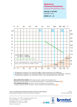
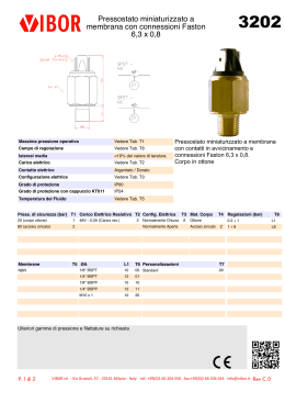
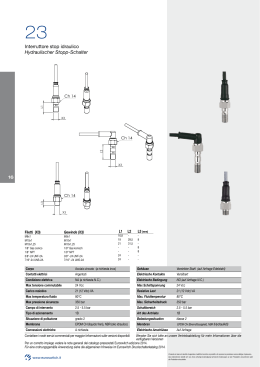
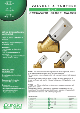
VIP
VALVOLA AUTOMATICA
AUTOMATIC VALVE
Attuatori pneumatici, Attuatori elettrici, Valvole a sfera manuali e automatizzate, Valvole
a farfalla manuali e automatizzate, Valvole pneumatiche assiali, Valvole a flusso avviato
pneumatic actuators, electric actuators, manual or actuator operated ball valves,
manual or actuator operated butterfly valves, co axial pneumatic valves, angle seat valves
QUALITA’ CERTIFICATA
CERTIFIED QUALITY
BESCHEINIGTE QUALITÄT
CALIDAD CERTIFICADA
La tecnologia e la flessibilità sono fattori determinanti
per la crescita della Omal.
L’azienda è specializzata nella produzione di attuatori pneumatici ed elettrici; valvole
comandate
pneumaticamente
ed
elettricamente;
valvole assiali on-off ; valvole a flusso avviato completati dalle
serie di accessori.
La scelta accurata delle materie prime e la tecnologia di
produzione all’avanguardia assicurano la massima qualità di prodotto lavorato e finito.
Technology and flexibility are determining factors in
Omal’s growth. The company is specialized in the production of pneumatic and electric actuators; pneumatically and electrically controlled valves; on-off axial valves; flow valves with a series of accessories. The careful
choice of raw materials and state-of-the-art production
technology ensure the highest quality processed and finished product.
VIP IS ONLY OMAL
Progettata per ottimizzare e semplificare l’automazione di impianti con sicurezza, affidabilità ed
economicità, la valvola VIP nasce per soddisfare le
esigenze della moderna impiantistica.
The VIP has been developed as the best and easy
solution for the installation of automatic plants with
safety, reliability and economic factors. The VIP is
born to satisfy all the needs of the modern plants.
Vantaggi della valvola VIP OMAL
Advantages of using an OMAL VIP
• Valvola automatica semplice e affidabile
• Easy and reliable automatic valve
• Ingombri e peso ridotti consentono installazioni
• Reduced weight and compact product save space
compatte
• Wide range of model and sizes
• Vasta gamma di modelli e misure
• Low air consumption
• Basso consumo d’aria
• Full bore
• Passaggio totale
• Very long working life
• Lunghissimo ciclo vitale
• Easy assembling in any position
• Facilità di montaggio in ogni posizione
• No external moving parts
• Assenza di parti mobili esterne (antinfortunistico)
• Inexpensive
• Costo ridotto
• Working independently from downstream or
• Funzionamento indipendente dalle pressioni a
monte e a valle del fluido intercettato
upstream pressure
VIP IS ONLY OMAL
Speziell
für
den
automatisierten
Anlagenbau
wurde
dieses pneumatisch gesteuerte Sperrventil von Omal
entwickelt.
Diseñada para optimizar y semplicar la automatizaciòn de las instalaciones con seguridad, fiabilidad y
economía, la vàlvula VIP ha nacido para satisfacer las
exigencias de las màs modernas instalaciones.
Ventajas de la vàlvula automàtica VIP OMAL:
VORTEILE DES OMAL VIP VENTILS
• Vàlvula automàtica sencilla y fiable.
• zuverlässig und anpassungsfähig
• kompakt
• Tamaño
ciòn
y
peso
reducidos,
• geringer Luftverbrauch zur Steuerung
• Paso total.
• in jeder Position einfach montierbar
utiliza-
en instalaciones compactas.
• Reducido consumo de aire.
• langlebig
su
• Amplia gama de modelos y medidas.
• fein abgestufte Baureihe
• 100% Durchgang
permitiendo
• Dilatadísimo ciclo vital.
• Fàcil de instalar en cualquier posiciòn.
• Ausencia de piezas mòviles externas (Mayor seguridad).
• keine beweglichen Außenteile (Unfallverhütung)
• Bajo coste.
• hervorragendes Preis-/Leistungsverhältnis
• Presiòn diferencial màxima (10 bar).
Le valvole VIP di intercettazione pneumatica, sono valvole
automatiche a passaggio totale. Vengono realizzate nelle
versioni doppio e semplice effetto (sia normalmente aperte
che normalmente chiuse) con attacchi filettati di vario tipo e
flangiati. Le valvole VIP sono pilotate con aria compressa
filtrata non necessariamente lubrificata (attacchi NAMUR).
In caso di lubrificazione utilizzare olio compatibile con le
guarnizioni. La pressione di alimentazione deve essere
compresa tra 3 e 8 bar nella versione doppio effetto e tra 4,2
e 8 bar nella versione semplice effetto.
Disponibili con guarnizioni in EPDM, Viton o NBR intercettano
fluidi fino alla pressione di 10 bar con temperature da -20°C a
+150°C (+80°C NBR).
La tenuta al vuoto é 740 mm Hg corrispondente ad un vuoto
del 97,4%.
Con temperature di utilizzo inferiori a 80°C tutte le valvole Vip
possono essere dotate di finecorsa magnetici esterni (da specificare in fase d’ordine).
VIP sind automatische Ventile mit 100% Durchgang. Das
VIP Ventil ist in den doppeltwirkenden und einfachwirkenden (normalerweise sowohl geöffnet als auch geschlossen)
Ausführungen mit Gewinde- oder Flanschanschlüsse lieferbar. Die Steuerung erfolgt mit gefilterter (trocken oder
geschmiert) Druckluft (Namur-Anschluß). Zur Schmierung
kann öl verwendet werden, das sich mit den dichtungen
verträgt. Die doppeltwirkende Ausführung benötigt einen
Steuerdruck zwischen 3 und 8 bar; bei der einfachwirkenden
Ausführung ist der Minimalwert 4,2 bar.
Durch die Auswahl der entsprechenden Dichtung (EPDM,
Viton, NBR) können die Ventile im Temperaturbereich von 20°C bis +150°C (+80°C mit NBR) eingesetzt werden.
Max. Betriebsdruck: 10 bar
Der Vakuumwert ist 97,4% (Vakuumdichtigkeit 740 mm Hg).
Bei Temperaturen unter 80°C können magnetische Endschalter
eingebaut werden (bei
dem auf mitzubestellen).
I dati e le caratteristiche di questo opuscolo potrebbero essere variati a scopo di miglioramento tecnico anche
senza preavviso e, pertanto non sono vincolanti ai fini della fornitura.
Änderungen vorbehalten.
The ON-OFF VIP are automated full bore valves. They are
realised in double actting and spring return (normally open
and normally closed) version with threaded ends or flanged.
The VIP are supplied with filtered compressed air not necessarily lubricated (connections as per NAMUR interface). In
case of lubrication, use oil compatible with the seals.
Working pressure must be between 3 and 8 bar in double
acting execution and between 4,2 and 8 bar in the spring
return execution.
Available with EPDM, Viton and NBR seals, VIP is used with
fluid at a max pressure of 10 bar and a temperature range
of -20°C and +150°C (+80°C NBR).
Vacuum tightness is 740 mm Hg that is equal to 97,4%. VIP
can be provided with external limit switches, only if a VIP is
used at a temperature below +80°C.
Las vàlvulas VIP de interrupciòn neumàtica son vàlvulas
automàticas de paso total. Estàn previstar para las versiones de simple y doble efecto (tanto normalmente abiertas
como normalmente cerradas), con conexiones roscadas
de 3/8” a 2” o con bridas. Las vàlvulas VIP se accionan
mediante aire comprimido que no es preciso que sea lubrificado (conexiòn NAMUR). La presiòn de alimentaciòn debe
estar comprendida entre 3 y 8-bar para las versiones de
doble efecto y entre 4,2 y 8 bar para las versiones de simple
efecto. Se hallan disponibles con juntas de EPDM, Viton ò
NBR para presiòn màxima de trabajo de 10 bar, a temperaturas de -20°C a +150°C (+80°C para NBR).
Su estanqueidad al vacío es de 740 mm Hg, correspondientes
a un vacío del 97,4%.
Con temperaturas de utilizaciòn inferiores a 80°C, todas las
vàlvulas VIP pueden estar dotadas de finales de carrera
magnéticos externos (a especificar en el pedido).
OMAL will be free to change all specifications and data included in this catalougue at any time, so as to
improve the quality and the performance of its products.
A efectos de su mejora técnica, los datos y caracteristicas indicadas en este folleto pueden ser modificadas
sin previo aviso y por lo tanto, no son vinculantes para los fines de entrega.
FUNZIONAMENTO WORKING
Nella progettazione della valvola Vip si é posta particolare attenzione alla realizazione del condotto passante
per garantire il passaggio totale e minimizzare le perdite di carico.
A lato il DIAGRAMMA PORTATA - PERDITA DI CARICO E COEFFICIENTE NOMINALE Kv. Il valore Kv é
il valore indice in m /h (con acqua a 15°C) provocante la caduta di pressione di 1 bar.
Bei diesem Ventil konnte die Forderung nach 100%
Durchfluß mit minimalen Strömungsverlust realisiert
werden.
Fl u s s - D r u c k v e r l u s t
Diagramm
und
Nennkoeffizent Kv. Der Kv Wert ist der Kennwert
in
m /h
(mit
Wasser
bei
15°C),
der
einen
Druckverlust von 1 bar verursacht.
Projecting the VIP we have carefully studied the fluid
passage to garantee the full boring and to minimize
losses of head.
FLOW-PRESSURE
DIAGRAM
PRESSURE
LOSS
AND Kv NOMINAL COEFFICIENT. Kv is the coefficient, expressed in m /h (with water at 15°C)
causing a pressure loss of 1 bar.
En el diseño de la vàlvula VIP se ha prestado una atenciòn especial a la ejecuciòn del conducto de paso del
fluido, a fin de garantizar el paso total y minimizar las
pérdidas de carga.
Al lado, se muestra el diagrama de CAUDAL - PERDIDA DE CARGA y COEFICIENTE NOMINAL Kv. El
valor Kv es el valor índice en m /h (con agua a 15°C),
que origina la pérdida de presiòn de 1 bar.
3
3
3
3
VALVOLA CHIUSA
CLOSE VALVE
Immettendo aria nel foro di comando “A”, il pistone va
a premere sulla guarnizione del seggio chiudendo la
valvola. Nelle versioni Semplice Effetto N.C. la molla é
alloggiata nella camera “A”: la posizione preferenziale
é quindi quella chiusa.
Supplying air through the hole “A”, the piston moves
towards the sleeve pressing the seals closing the
valve. In the spring return N.C. version the spring is
in the “A” chamber, therefore the preferential position is closed.
GESCHLOSSENES VENTIL
Führt man Druckluft durch “A” ein, so verschiebt sich
der Kolben nach rechts und drückt sich gegen die
Anschlagsdichtung: das Ventil ist gesperrt.
Bei der einfachwirkenden normalerweise geschlossen
Ausführung befindet sich eine Feder in der Kammer
“A”: die Vorzugsstellung ist daher die geschlossene.
VALVULA CERRADA
Admitiendo aire en el orificio de mando “A”, el pistòn,
presiona la junta del asiento, cerrando la vàlvula. En
las versiones de Simple Efecto N.C. el muelle està
alojado en la càmara “A”. La posiciòn de reposo es de
vàlvula cerrada.
PERDITA DI CARICO LOSSES
DRUCKVERLUST PERDIDA DE CARGA
∆p - bar
BETRIEB FUNCIONAMENTO
PORTATA FLOW PRESSURE DURCHFLUSSWERT CAUDAL
Q=m /h
3
VALVOLA APERTA
OPEN VALVE
Immettendo aria nel foro di comando “B”, il pistone
si stacca dalla guarnizione del seggio aprendo la valvola. Nelle versioni Semplice Effetto N.A. la molla é
alloggiata nella camera “B”: la posizione preferenziale é quindi quella aperta.
Supplying air through the hole “B”, the piston moves
backwards opening the valve. In the spring return
N.O. version the spring is in the “B” chamber, therefore the preferential position is open.
OFFENES VENTIL
VALVULA ABIERTA
Führt man Druckluft durch “B” ein, so verschiebt
sich der Kolben nach links und trennt sich von der
Anschlagsdichtung: das Ventil ist geöffnet.
Bei der einfachwirkenden normalerweise geöffnet
Ausführung befindet sich eine Feder in der Kammer
“B”: die Vorzugsstellung ist daher die geöffnete.
Admitiendo aire en el orificio de mando “B”, el pistòn,
se separa de la junta del asiento, abriendo la vàlvula.
En las versiones de Simple Efecto N.A. el muelle està
alojado en la càmara “B”. La posiciòn de reposo es de
vàlvula abierta.
NAMUR
45
12
M5
32
øB
A
E
1/8”
27
F
c
I
ch. D
TABELLA DIMENSIONALE
GB
DIMENSION TABLE
15
20
25
32
40
50
mm.
10
15
20
25
32
40
GAS
10
nominal diameter
misura F
3/8”
1/2”
3/4”
1”
1”1/4
1”1/2
2”
size F
GAS
3/8”
1/2”
3/4”
1”
1”1/4
1”1/2
2”
diametro passaggio
mm.
10
15
20
25
32
40
50
bore
mm.
10
15
20
25
32
40
50
A
mm.
53,8
60
70
76
91,25
102
115
A
mm.
53,8
60
70
76
91,25
102
115
ØB
mm.
46
51,7
63,5
69
86
96
109
ØB
mm.
46
51,7
63,5
69
86
96
109
C
mm.
98
112
135
143
165
180
207
C
mm.
98
112
135
143
165
180
207
chiave D
mm.
22
27
33
41
50
60
75
wrench D
mm.
22
27
33
41
50
60
75
E
mm.
30,8
33,3
38,25
41,5
48,25
53,75 59,75
E
mm.
30,8
33,3
diametro nominale
mm.
38,25
41,5
0,08
50
48,25 53,75 59,75
doppio effetto
dm3/ciclo
0,024 0,035 0,063
0,08
0,15
0,219
0,31
air consumption double acting
dm3/cycle
0,024
0,035
0,063
0,15
0,219 0,31
consumo aria semplice effetto
dm3/ciclo
0,012 0,017 0,031
0,04
0,075
0,109 0,155
air consumption spring return
dm3/cycle
0,012
0,017
0,031 0,04
0,075
0,109 0,155
consumo aria
peso doppio effetto
Kg.
0,8
1
1,59
1,8
3,13
3,5
5,5
weight double acting
Kg.
0,8
1
1,59
1,8
3,13
3,5
5,5
peso semplice effetto Kg.
0,85
1,05
1,69
1,88
3,41
3,7
5,8
weight spring return
Kg.
0,85
1,05
1,69
1,88
3,41
3,7
5,8
50
D
E
MASSTABELLE
TABLA DE DIMENSIONES
Nennweite
mm.
10
15
20
25
32
40
50
diàmetro nominal
mm.
10
15
20
25
32
40
Maße F
GAS
3/8”
1/2”
3/4”
1”
1”1/4
1”1/2
2”
medida F
GAS
3/8”
1/2”
3/4”
1”
1”1/4
1”1/2
2”
Durchgang
mm.
10
15
20
25
32
40
50
diàmetro de paso
mm.
10
15
20
25
32
40
50
A
mm.
53,8
60
70
76
91,25
102
115
A
mm.
53,8
60
70
76
91,25
102
115
ØB
mm.
46
51,7
63,5
69
86
96
109
ØB
mm.
46
51,7
63,5
69
86
96
109
C
mm.
98
112
135
143
165
180
207
C
mm.
98
112
135
143
165
180
207
Sechskante-Schlüßel D mm.
22
27
33
41
50
60
75
ch. D
mm.
22
27
33
41
50
60
75
30,8
33,3
38,25
41,5
48,25
53,75 59,75
E
mm. 30,8
33,3
38,25
41,5
48,25
53,75 59,75
consumo aire
doble efecto
dm3/ciclo
0,024 0,035 0,063
0,08
0,15
0,219 0,31
consumo aire
simple efecto
dm3/ciclo
0,012 0,017 0,031
0,04
0,075
0,109 0,155
1,8
3,13
E
mm.
Luftverbrauch doppeltwirkend
dm3/Zyk.
0,024 0,035 0,063
0,08
0,15
0,219
Luftverbrauch einfachwirkend
dm /Zyk.
0,012 0,017 0,031
0,04
0,075
0,109 0,155
1,8
3,13
Gewicht
doppeltwirkend
3
Kg.
0,8
1
1,59
3,5
0,31
5,5
peso doble efecto
Kg.
0,8
1
1,59
3,5
5,5
1
11
10
9
8
2
3
I
N° di pezzi
Particolare
1
2
3
4
5
6
7
8
9
10
11
Corpo
Pistone
Guarnizioni a labbro
O-Ring per stelo
Molla N.A./N.C.
Guarnizione di battuta
Manicotto
Seggio di tenuta
O-Ring
Ghiera di battuta
O-Ring pistone
N°
1
2
3
4
5
6
7
8
9
10
11
1
1
2
2
1
1
1
1
1
1
1
Beschreibung
Gehäuse
Kolben
Lippendichtungen
Schaft-o-ring
Feder N.A./N.C.
Anschlagsdichtung
Muffe
Ventilsitz
O-Ring
Anschlagsmutternut
Kolben O-Ring
7
MATERIAL TABLE
N°
Description
EN 12165 CW617N Nichelato
1
2
3
4
5
6
7
8
9
10
11
Body
Piston
Lip seals
Stem O-Ring
Spring N.O./N.C.
Seat seal
Sleeve
Seat
Sleeve O-Ring
Seat nut
Piston O-Ring
EN 12164 CW614N Nichelato
NBR / Viton / EPDM
NBR / Viton / EPDM
Acciaio per molle
NBR / Viton / EPDM
EN 12165 CW617N Nichelato
EN 12165 CW617N Nichelato
NBR / Viton / EPDM
EN 12164 CW614N Nichelato
NBR / Viton / EPDM
E
MATERIALTABELLE
N° Anz.
6
Materiale
doppio semplice
effetto
effetto
1
1
2
2
1
1
1
1
1
1
5
GB
TABELLA DEI MATERIALI
N°
D
4
doppelt
wirkend
einfach
wirkend
Materialien
N°
1
1
2
2
1
1
1
1
1
1
1
1
2
2
1
1
1
1
1
1
1
EN 12165 CW617N Vernickelt
1
2
3
4
5
6
7
8
9
10
11
EN 12164 CW614N Vernickelt
NBR / Viton / EPDM
NBR / Viton / EPDM
Stahl-Legierung
NBR / Viton / EPDM
EN 12165 CW617N Vernickelt
EN 12165 CW617N Vernickelt
NBR / Viton / EPDM
EN 12164 CW614N Vernickelt
NBR / Viton / EPDM
N°of pieces
double
acting
spring
return
Materials
1
1
2
2
1
1
1
1
1
1
1
1
2
2
1
1
1
1
1
1
1
EN 12165 CW617N Nickel-pl.
EN 12164 CW614N Nickel-pl.
NBR / Viton / EPDM
NBR / Viton / EPDM
Steel
NBR / Viton / EPDM
EN 12165 CW617N Nickel-pl.
EN 12165 CW617N Nickel-pl.
NBR / Viton / EPDM
EN 12164 CW614N Nickel-pl.
NBR / Viton / EPDM
TABLA DE MATERIALES
Detalle
Cuerpo
Pistòn
Junta de labios
Tòrica del eje
Muelle N.A./N.C.
Junta de asiento
Manguito (roscado)
Asiento del cierre
Tòrica del manguito
Arandela de presiòn
Tòrica del pistòn
N° piezas
doble
efecto
simple
efecto
Material
1
1
2
2
1
1
1
1
1
1
1
1
2
2
1
1
1
1
1
1
1
EN 12165 CW617N Niquelado
EN 12164 CW614N Niquelado
NBR / Viton / EPDM
NBR / Viton / EPDM
Acero para muelles
NBR / Viton / EPDM
EN 12165 CW617N Niquelado
EN 12165 CW617N Niquelado
NBR / Viton / EPDM
EN 12164 CW614N Niquelado
NBR / Viton / EPDM
Carta utilizzata - Paper used: Symbol Freelife Satin certificata FSC Mixed Sources COC - 000010
OMAL S.P.A.
Via Ponte Nuovo, 11 25050 Rodengo Saiano Brescia Italy - Tel. +390308900145 r.a.
http://www.omal.com - http://www.omal.it - E-mail: [email protected]
Scaricare