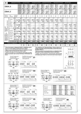
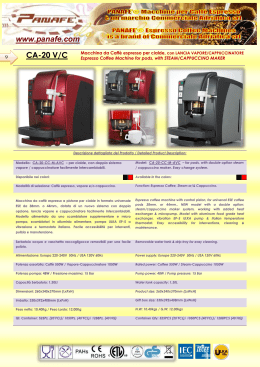
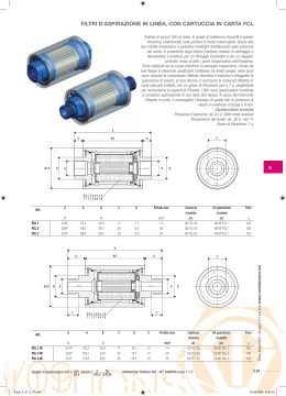
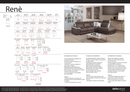
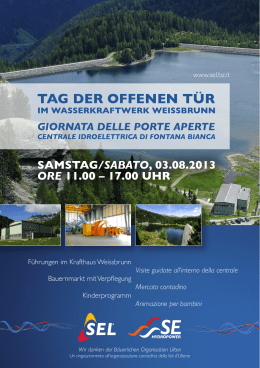
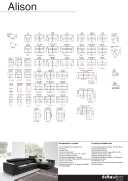
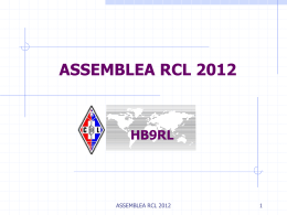
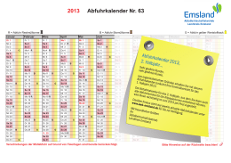
I TA L I A N O
CDH
Istruzione per il montaggio e la manutenzione per
“AEROEVAPORATORI INDUSTRIALI A DOPPIO FLUSSO
ENGLISH
FRANCAIS
DEUTSCH
РУССКИЙ
Installation and maintenance instruction for
“DUAL DISCHARGE INDUSTRIAL UNIT COOLERS”.
Instruction pour le montage et l’entretien pour
“EVAPORATEURS VENTILES INDUSTRIELS DOUBLE FLUX”.
Montage und wartungsanleitung für
“INDUSTRIE ZWEISEITIG AUSBLASENDE HOCHLEISTUNGSLUFTKÜ HLER”.
Инструкция по установке и обслуживанию для
“2-х ПОТОЧНЫХ ПРОМЫШЛЕННЫХ ВОЗДУХООХЛАДИТЕЛЕЙ”.
1
I TA L IA N O
Dichiarazione del fabbricante.
N O R M E - Gli apparecchi sono stati progettati e costruiti per poter essere incorporati in macchine
co- me definito dalla Direttiva Macchine 2006/42CE e successivi emendamenti.
• EN 60335-1 (CEI 61-50) Sicurezza degli apparecchi elettrici d’uso domestico e similare. Norme Generali.
• Direttiva 2004CE e successivi emendamenti. Compatibilità elettromagnetica.
• Bassa tensione - Riferimento Direttiva 2006/95CE - EN 294 Griglie di protezione
Tuttavia non è ammesso mettere i nostri prodotti in funzione prima che la macchina nella quale essi
sono incorporati o della quale essi sono una parte sia stata dichiarata conforme alla legislazione in vigore.
PRECAUZIONI: Messa in guardia contro eventuali rischi d’infortunio o di danneggiamento dei materiali in caso d’inosservanza delle istruzioni.
A) Per le operazioni di movimentazione, installazione e manutenzione, è obbligatorio:
1 - Personale abilitato all’uso dei mezzi di movimentazione (gru, carrello elevatore, etc.).
2 - Uso dei guanti di protezione.
3 - Non sostare sotto il carico sospeso.
B) Prima di procedere ai collegamenti elettrici, è obbligatorio:
1 - Personale abilitato.
2 - Assicurarsi che il circuito elettrico d’alimentazione sia aperto.
3 - L’interruttore del quadro generale d’alimentazione sia lucchettato in posizione di aperto.
C) Prima di procedere ai collegamenti dei collettori/distributori, è obbligatorio:
1 - Personale abilitato.
2 - Assicurarsi che il circuito d’alimentazione sia chiuso (assenza di pressione).
3 - Durante l’operazione di saldatura, assicurarsi di indirizzare la fiamma in modo da non investire la macchina (eventualmente interporre una protezione).
D) SMALTIMENTO: I prodotti LU-VE sono composti da:
Materiali plastici: polistirolo, ABS, gomma.
Materiali metallici: ferro, acciaio inox, rame, alluminio (eventualmente trattati).
Per i liquidi refrigeranti seguire le istruzioni dell’installatore dell’impianto.
E) Togliere la pellicola trasparente di protezione dalle parti metalliche verniciate.
FRANCAIS
Declaration d’incorporation du constructeur.
NORMES - Les produits sont conçus et costruits pour pouvoir être incorporés dans les machines
comme défini par la directive européenne 2006/42CE et amendements successifs.
• Directive 2004/108/CE et amendements successifs. Compatibilité électromagnétique.
• Basse tension - Référence Directive 2006/95CE - EN 294 Grilles de protection.
Toutefois, il n’est pas admis de mettre nos produits en fonctionnement avant que la machine dans laquelle ils sont incorporés ou de laquelle ils sont une partie, ne soit considérée et déclarée conforme
à la législation en vigueur incluant les produits objet de cette déclaration.
PRECAUTIONS: Mise en garde contre d’éventuels risques d’accident ou d’endommagement des appareils en cas de non-observation des instrustions.
A) Pour les opérations de manutention, installation et maintenance, est obligatoire:
1 - L’intervention d’ un opérateur autorisé à l’ usage des appareils de manutention (grue, chariot
élévateur, etc.).
2 - L’utilisation des gants de protection.
3 - De ne pas stationner en dessous d’une charge suspendue.
B) Avant de procéder aux raccordements électriques, est obligatoire:
1 - L’intervention d’un opérateur autorisé.
2 - De s’assurer que le circuit électrique d’alimentation est ouvert.
3 - De s’assurer que l’interrupteur du boîtier général d’alimentation est bloqué par un cadenas en
position ouverte.
C) Avant de procéder aux raccordements des collesteurs/distributeurs, est obligatoire:
1 - L’intervention d’un opérateur autorisé.
2 - De s’assurer que le circuit d’alimentation est fermé (absence de pression).
3 - Durant la soudure, de veiller à diriger la flamme de façon à ne pas toucher la machine
(éventuellement, il conviendra de placer une protection devant la machine).
D) ELIMINATION: Les produits LU-VE sont composés de:
Matériaux plastiques: Polystyrène, ABS, caoutchouc.
Matériaux métalliques: fer, acier inox, cuivre, aluminium (éventuellement traité).
Pour les liquides de refroidissement, suivre les instructions de l’installateur de l’appareil.
E) Ôter la pellicule transparente de protection des parties métalliques peintes.
ESPAÑOL
DECLARACÍON del fabricante.
НОРМЫ – Продукция предназначена для включения в агрегаты, как это определено в
Директиве ЕС 2006/42CE для машин и ее последующих модификациях.
- Директива 2004/108/CE и ее последующие модификации. Электромагнитная
совместимость
- Низкое напряжение – Соответствующая Директива 2006/95/CE. Решетки
вентиляторов
Зпрещено эксплуатировать оборудование до того, как оно будет установлено на конечный
агрегат или станет его частью, как это определено в Директиве ЕС для машин.
ВНИМАНИЕ: Несоблюдение следующих инструкций может повлечь травмирование
персонала и порчу оборудования
A) Для передвижения и монтажа и обслуживания оборудования необходимо::
1 – Привлечение только квалифицированного персонала для работы с подъемными
механизмами (краны, подъемники и т.п.)
2 – Использовать рабочие перчатки
3 – Не стоять под грузом.
B) Для проведения электромонтажных работ необходимо:
1 – Привлекать квалифицированный персонал.
2 – Убедиться в отсутствии напряжения на линии
3 – Убедиться, что основной выключатель разомкнут и заблокирован в этом положении.
C) Для электромонтажных работ с коллекторами/распределителями необходимо:
1 – Привлекать только квалифицированный персонал.
2 – Убедиться, что нет даления в контуре.
3 – Во время сварочных работ не направлять пламя горелки на оборудование (использовать
при необходимости прокладку)
D) УТИЛИЗАЦИЯ: Продукция ЛЮ-ВЭ изготовлена из:
Пластиковых материалов: полиэтилен, ABS, резина.
Металла: железо, сталь, медь, алюминий (возможно переработанный).
Е) Удалите защитную пленку с металлических частей.
E) Eliminar la protección plástica transparente de las partes metalicás pintadas.
2
ENGLISH
M A N U FA C T U R E R S D E C L A R AT I O N O F I N C O R P O R AT I O N .
S TANDADS - The products are provided for incorporation in machines as defined in the EC Machine
Directive 2006/42CE and subsequent modifications.
• Machine Directive 2004/108/CE and subsequent modifications. Electromagnetic compatibility.
• Low tension - Reference Directive 2006/95/CE - EN 294 Fan guards.
However it is not allowed to operate our equipment in advance before the machine incorporating the products or making part thereof has been declared conforming to the EC Machine Directive.
PRECAUTIONS: Accidents warning to personal injury or equipment damage due to negligence for complying to instructions.
A) For moving installing and maintenance operations it is mandatory to comply as follows:
1 - Employ authorized personnel only for using moving equipment (cranes, fork elevators, etc.).
2 - Wearing of work gloves.
3 - Never stop below a suspended load.
B) Before to proceed with elestrical wirings it is mandatory to comply as follows:
1 - Authorized personnel only shall be employed.
2 - Make sure the power line circuit is open.
3 - The main switch on the general power panel is open and pad-locked in this setting.
C) Before to proceed with the collectors/distributors connections it is mandatory to
comply as follows:
1 - Authorized personnel only shall be employed.
2 - Make sure the supply circuit is closed (no pressure).
3 - When performing welding operations, make sure the flame nozzle is not aimed toward the
equipment (insert a shield if required).
D) DISPOSAL: LU-VE products are made of:
Plastic materials: polyethylene, ABS, rubber.
Ferrous materials: iron, stainless steel, copper, aluminium (possibly processed).
Refrigerants liquids: follow the instructions relevant to the equipment installation.
E) Remove the transparent protection film from varnished metallic parts.
DEUTSCH
HERSTELLER-ERKLÄ RUNG
NORMEN - Die Produkte sind in Überreistimmung mit der EG Richtlinie 2006/42CE und nachtfolgende
Ergänzungen entwickelt, konstruiert und gefertigt.
• Richtlinie 2004/108/CE und nachfolgende Ergänzungen. Elektromagnetische Kompatibilität.
• Niederspannung - Richtlinie 2006/95/CE - EN 294 Schutzgitter.
Die Inbetriebnahme dieser Maschine ist so lange untersagt, bis sichergestellt ist, daß die Anlage, in die sie
eingebaut wurde oder von welcher sie ein Teil ist, den Bestimmungen der EG Richtlinie Maschinen entspricht.
VORSICHTSMASSNAHMEN: Warnung vor Unfall- oder Materialschadensgefahren bei
Vorletzung der Vorschriften.
A) Für den Innerbetrieblichen Transport, die Installation und die Wartung müssen
folgende Vorschriften eingehalten werden:
1 - Das Personal muß für die Bedienung von innerbetrieblichen Transporteinrichtungen (Krane,
Hubkarren usw.) befähigt sein.
2 - Gebrauch von Schutzhandschuhen.
3 - Kein Aufenthalt von Personen unter hängenden Lasten.
B) Vor Ausführung der Elektroanschlüsse müssen folgende Vorschriften eingehalten werden:
1 - Fachkundiges Personal.
2 - Sicherstellen, daß der Stromversorgungskreis offen ist.
3 - Der Schalter am Hauptstromversorgungs-Schaltschrank muß mit einem Schloß
versehen und geöffnet sein.
C) Vor Anschluss der Sammelrohre/Verteilerrohre müssen folgende Vorschriften eingehalten werden:
1 - Fachkundiges Personal.
2 - Sicherstellen, daß der Speisungskreis geschlossen ist (kein Druck).
3 - Beim Schweißen die Flamme so ausrichten, daß die Maschine nicht getroffen wird (eventuell
mit einem Schutz versehen).
D) ENTSORGUNG: Die LU-VE-Produkte bestehen aus:
Plastmaterialien: Polystyrol, ABS, Gummi.
Metallmaterialien: Eisen, rostfreier Stahl, Kupfer, Aluminium (eventuell behandelt).
Bezüglich der Kühlflüssigkeiten sind die Vorschriften des Anlageninstallateurs zu beachten.
E) Die transparente Plastfolie von den lackierten Metallteilen entfernen.
SOLLEVAMENTO
/
LIFTING SKETCH
/
SOULEVEMENT
SI - YES - OUI
JA - SI
/
ANHEBEN
ПОДЪЕМ
/
• Smontare il coperchio “1”, sollevare la cassa al soffitto “2 - 3”usando un carrello a forche facendo
passare negli appositi fori i tiranti di sostegno”4” . Bloccare i dadi dei tiranti di sostegno “5” interponendo una rondella di bloccaggio. Togliere i bulloni “6”. Abbassare la cassa“7”.
• Lift the crate to the ceiling “1”, preferably by use of forklift truck “2-3”. Feed securing coach bolts
through proper holes in the supporting bars of the unit cooler ”4”. Securely tighten the nuts on through bolts “5”, interposing a washer. Remove bolts “6”. Lower empty crate “7”.
• Enlever ensuite le couvercle “1”, élever la caisse au plafond “2 - 3”, au moyen d’un charot éléva-
teur, et placer les tirants d’appui dans les trous appropriés ”4”. Serrer les écrous des tirants d’appui “5”en y interposant une rondelle di fixation. Enlever les boulons “6”. Baisser la caisse “7”.
• Der Verschlag ist mit Hilfe“1” eines Hubstaplers zur Dekke zu heben “2 - 3”. Die Bolzen für die Be-
NO - NO - NON
NEIN - NO
festigung sind durch die entsprechenden Löcher der Kühleraufhängung zu führen”4”. Die Muttern
“5” sind unter Verwendung einer Beilagscheibe festzuziehen. Die Bolzen “6” sind zu entfernen. Der
leere verschlag ist herabzulassen “7”.
2000
mim.
•
Поднимите упаковку к потолку”1”, желательно используя вилочный подъемник “2-3”.
Вставьте страховочные болты в соответствующие отверстия в поддерживающей балке
воздухоохладителя ”4”. Затяните гайки на болтах “5”, используя шайбы. Удалите болты “6” .
Опустите упаковку “7”.
4
5
6
• È importante che l’apparecchio sia sistemato in modo da lasciare uno spazio laterale pari alla sua lunghezza. Ciò per consentire l’eventuale sostituzione delle resistenze elettriche (ES).
• It’s important that the unit cooler is installed so as to leave space to the left of cooler (i.e. facing fans) for
(ES) electric heaters removal.
• Il est important de noter que l’appareil de-
•
vra toujours être installé avec un espace
latéral libre égal a sa longueur, ceci pour
l’eventuel remplacement des résistance
électriques (ES).
Die Verdampfer müssen mit einem Seitenabstand, der genauso Groß ist wie die
Verdampfer lang sind, montiert werde, um
den Austausch der Abtauheizstäbe zü
gewährleisten (ES).
6
6
6
6
• Важно установить охладитель с зазором слева (вид спереди) для возможности снятия электрических
нагревателей (ES).
7
/
INSTALLATION
/
INSTALLATION
A
/
Modello Modè le Модель
MONTAGE
n°
A mm
B
30 x 20
GAS
1”1/4
2
2050
3
2850
4
3650
B
mm
800
1600
2400
3200
C
D
A
mm
mm
mm
–
1355
1650
1355
2850
800
1355
4050
1600
1355
5250
CD63H
CD64H
B
C
D
mm
mm
mm
1200
–
1775
2400
1775
3600
1200
1775
4800
2400
1775
CD45H
D
225
1
1250
CD45H
CD63- 64H
395
225
1”1/4
Elettroventilatori - Fans motor - Ventilateurs
Ventilatoren - Моторы вентиляторов
Type Modell
D
C
/ ИНСТАЛЛЯЦИЯ
475
INSTALLAZIONE
GAS
3
ATTACCHI
/
CONNECTIONS
/
RACCORDS
/
ANSCHLÜ SSE
/
СОЕДИНЕНИЯ
• Prima di procedere ai collegamenti dei collettori/distributori, è obbligatorio: assicurarsi che il circuito d’alimentazione sia chiuso (assenza di pressione).
Durante l’operazione di saldatura, assicurarsi di indirizzare la fiamma in modo da non investire la macchina
(eventualmente interporre una protezione).
• Before to proceed with the collectors/distributors connections it is mandatory to comply as follows:
Make sure the supply circuit is closed (no pressure).
When performing welding operations, make sure the flame nozzle is not aimed toward the equipment (insert a shield of required).
• Avant de procé der aux raccordements des collesteurs/distributeurs, est obligatoire: De s’assurer que
le circuit d’alimentation est fermé (absence de pression).
Durant la soudure, de veiller à diriger la flamme de façon à ne pas toucher la machine (éventuellement, il
conviendra de placer une protection devant la machine).
SI - YES - OUI
JA - ДА
NO - NO - NON
NEIN - НЕТ
• Vor Anschluss der Sammelrohre/Verteilerrohre mü ssen folgende Vorschriften eingehalten werden:
Sicherstellen, daß der Speisungskreis geschlossen ist (kein Druck).
Beim Schweißen die Flamme so ausrichten, daß die Maschine nicht getroffen wird (eventuell mit einem
Schutz versehen).
• Non adattare la posizione dei collettori alla linea.
• Do not adapt headers position to the suction line
• Ne pas adapter la position du collecteurs à la ligne.
• Sammlerposition nicht an Leitung anpassen !
• Установка наконечников к линии всоса
COLLEGAMENTI
/ CONNECTIONS
• Перед началом соедининия коллекторов/дистрибьтеров необходимо: убедиться, что нет давления в
подающем контуре
Во время сварочных работ не направлять пламя горелки на оборудование (при необходимости поместить
прокладку)
/
RACCORDEMENTS
• COLLEGAMENTO TUBAZIONI SCARICO ACQUA: avvitare allo scarico delle bacinelle un gomito a 60° (A).
È necessario che, sia la valvola solenoide che l’eventuale rubinetto a mano per il comando della mandata dell’acqua, siano installati all’esterno della cella, ad un livello
più basso dell’evaporatore. Su questa linea verrà installato inoltre un (T), all’estremità
del quale si collegherà un tubetto disperdente che servirà a mantenere scarico il tratto di tubazione che va dalla solenoide all’evaporatoe per evitare il congelamento dell’acqua.
/ ANSCHLÜ SSE
/ СОЕДИНЕНИЯ
• WATER DRAIN TUBING CONNECTION: fit a 60° elbow (A), to the drain tray.
It’s essential that the control valve, either hand or automatic, be fitted outside the cold room and at a lower
level than the evaporator, and a drain off (TEE) piece should be fitted with a bleed tube to allow water left
in the feed pipe to the cooler to drayn away when the control valve close.
• CONNECTION TUBE É VACUATION D’EAU: vissere une coude filetée de 60° (A) a la sortie des egouttoirs.
La vanne solénoide et éventuellement la vanne à main pour la commande de l’eau seront installées a
l’extérieur de la chambre froide à un nuveau plus bas que celui de l’évaporateur. On installera en outre sur
cette conduite un (T) à l’extrémité duquel un tube déperditeur servira de vidange à la partie de la conduite située entre la vanne solenoide et l’évaporateur; ceci pour eviter le danger de gel de l’eau.
• TROPFWASSERANSCHLUSS: montiere einen 60° Bogen (A).
Es ist wichtig, dass das Wasser-Regel-Ventil (hand oder automatisch) ausserhalb del Kühlraums un Tiefer als der Verdampfer installiert wird und dass ein T-Stück, wie nachstehend abgebildet, eingebaut wird,
der eine abzweig am T-Stück sollte stark reduziert sein, sodass wahrend des Abtauens nur wenig Wasser ausfliessen kann und sich nach schliessen des Ventils die Wasserzuleitung entleeren kann.
• СОЕДИНЕНИЕ ДРЕНАЖНЫХ ТРУБОК: соединить под углом 60° (A) к дренажному поддону.
Важно, чтобы контрольный клапан, как автоматический, так и ручной, был расположен вне
холодильной камеры и ниже по уровню, чем испаритель, и дренажный отвод (T), имел трубку для
стока воды в трубе подачи к охладителю для дренажа при закрытом клапане.
VERIFICHE
/
COOLER CAPACITY CHECKS
/
CONTROLES
/
LEISTUNGSUBERPRUFUNG
/
КОНТРОЛЛЕРЫ
• VERIFICHE - Rilevare le seguenti temperature e pressioni:
Ts’ - Temperatura di cella nella zona aria ingresso all’evaporatore.
Te
- Temperatura di evaporazione, corrispondente alla pressione del refrigerante all’uscita dell’evaporatore.
Trs - Temperatura di surriscaldamento del refrigerante, sulla linea di aspirazione in prossimità del bulbo della valvola termostatica.
N.B. - Per una utilizzazione ottimizzata dell’evaporatore il surriscaldamento (Trs-Te) non dovrà
superare 0,7 x (Ts’-Te).
• CONTROLES - Relever les températures et pressions suivantes:
Ts’ - Témperature de la chambre froide dans la zone d’entrée d’air de l’évaporateur.
Te
- Témperature d’évaporation, correspondante à la pression du réfrigérant à la sortie de l’évaporateur.
Trs - Témperature de surchauffe du réfrigérant, sur la ligne d’aspiration à proximité du bulbe de la
vanne thermostatique.
N.B. - Pour utiliser l’aé roé vaporateur dans les conditions optimales, la surchauffe (Trs-Te) ne
doit pas ê tre supé rieure à 0,7 x (Ts’-Te).
• COOLER CAPACITY CHECKS - Take the following temperature and pressures:
Ts’ - Cold room air inlet temperature to the unit.
Te
- Evaporating temperature, relating to the refrigerant pressure on the unit cooler outlet.
Trs - Refrigerant superheat temperature, on suction line near thermostatic valve bulb.
N.B. - For otimum unit cooler performance the superheat (Trs-Te) shoud not be higher than
0,7 x (Ts’-Te).
• LEISTUNGSUBERPRUFUNG - Folgende Temperaturen und Drücke sind zu messen:
Ts’ - Kühlraumtemperatur an der Lufteintrittsseite des Verdampfers.
Te
- Verdampfungstemperatur über Druck am Verdampferende.
Trs - Fühlertemperatur an der Saugleitung nahe beim Fühler des Expansionventils.
N.B. - Fü r eine optimale Verdampferarbeitsweise darf die Ü berhitzung (Trs-Te) nicht hö her sein
als 0,7 x (Ts’-Te).
• КОНТРОЛЛЕРЫ МОЩНОСТИ - Температура и давление:
Ts’ - Температурахолодильной камеры навходе.
Te
- Температура испарения, относительно давления агента навыходе
Trs - Температура перегревана линиивсоса около клапанатермостата.
Nota - Для оптимальной работы охладителя температура перегрева (Trs – TE) не должна
быть выше 0,7 x (Ts’ - Te).
4
Ts’ Trs
Te
E
SBRINAMENTO ELETTRICO
Вентиляторы
Fans
Eléctrovent.
Electric heaters
Resistenze elettriche
Résistances électriques Heizstäbe
Электрические нагреватели
n°
/
DEGIVRAGE ELECTRIQUE / ELEKTRISCHE ABTAUUNG
8100-4
8200-6
8300-7
1
(1*) N°
ЭЛЕКТРОРАЗМОРОЗКА
/
8102-4
8202-6
8302-7
8104-4
8204-6
8304-7
8106-4
8206-6
8306-7
8108-4
8208-6
8308-7
1
2
2
3
8110-4
8210-6
8310-7
3
8112-4
8212-6
8312-7
8114-4
8214-6
8314-7
4
4
4
4
4
4
4
4
4
4
RCL8
850
-----
RCL8
850
2
FCL8
RCL16
1585
-----
RCL16
1585
2
FCL16
RCL24
2300
-----
RCL24
2300
2
FCL24
RCL32
3020
----
RCL32
3020
2
FCL32
--3400
2
FCL8
850
5100
2
FCL8
--6340
2
FCL16
1585
9510
2
FCL16
--9200
2
FCL24
2300
13800
2
FCL24
--12080
2
FCL32
3020
18120
2
FCL32
W
850
1
EB1
200
850
1
EB1
200
1585
1
EB1
200
1585
1
EB1
200
2300
1
EB1
200
2300
1
EB1
200
3020
1
EB1
200
3020
1
EB1
200
=W
1900
1900
3370
3370
4800
4800
6240
6240
TOT. (1*+2*+3*+4*) = W
5300
7000
9710
12880
14000
18600
18320
24360
Batteria
Mod. / Type
Coil
(230 V x n° 1)
W
(2*) N°
Batterie
Block
Mod. / Type
Теплообменник
Bacinella
Drain tray
Égouttoir
Trofwanne
Дренажный
поддон
(230 V) x n° 1) W
TOT. (1*+ 2*) = W
(3*) N°
Mod. / Type
(230 V x n° 1)
W
(4*) N°
Mod. / Type
(230 V x n° 1)
TOT. (3*+ 4*)
CD45H...E
ELECTRIC DEFROST
CD45H
CD45H
CD45H
CD45H...E
Elettrovent.
Ventilatoren
/
Schema di collegamento / Connection wiring / Schema de raccordement / Schaltbilder Zeichenerklä rung / Соединение проводов
01
02
01
02
Prima di procedere ai collegamenti elettrici, è obbligatorio assicurarsi che il circuito
elettrico d’alimentazione sia aperto.
Before to proceed with electrical wirings it is mandatory to comply as follows make sure the power line circuit is open.
Avant de procé der aux raccordements é lectriques, est obligatoire de s’assurer
que le circuit é lectrique d’alimentation est ouvert.
02
01
02
Vor Ausfü hrung der Elektroanschlü sse mü ssen folgende Vorschriften eingehalten
werden Sicherstellen, daß der Stromversorgungskreis offen ist.
Перед электромонтажными работами убедитесь в отсутствии напряжения на
линии
Schaltbilder Zeichenerklärung
Схема соединений
Schema di collegamento
Connection wiring
Schema de raccordement
01
RCL
U
FCL
Y
RCL
RCL
RCL
X
FCL
FCL
EB1
Z
RCL
RCL
01
Z
W
V
X
U1
U
U2
Y
V1
V
W1
W
V2
W2
FCL
EB1
1 2
3
N
STANDARD
Schaltbilder Zeichenerklärung
Схема соединений
Schema di collegamento
Connection wiring
Schema de raccordement
02
3~400 V 50-60 Hz
Z
X
U1
W1
FCL RCL
U
FCL
V
Y
RCL
RCL
RCL
X
FCL
FCL
FCL
FCL
EB1
Z
RCL
RCL FCL
Y
V1
W
U
U2
V
V2
W
W2
3~230 V 50-60 Hz
FCL
EB1
5
E
SBRINAMENTO ELETTRICO
ELECTRIC DEFROST
CD63H 8500-4
CD63H 8600-6
CD63H 8700-7
CD63H 8800-10
CD64H 9000-4
CD64H 9100-6
CD64H 9200-7
CD64H 9300-10
CD63H...E
CD64H...E
Elettrovent.
Ventilatoren
/
Вентиляторы
Fans
Eléctrovent.
n°
--8604-6
8704-7
8804-10
--9104-6
9204-7
9304-10
1
8506-4
8606-6
8706-7
8806-10
9006-4
9106-6
9206-7
9306-17
1
2
8508-4
8608-6
8708-7
8808-10
9008-4
9108-6
9208-7
9308-10
--8610-6
8710-7
8810-10
--9110-6
9210-7
9310-10
2
ЭЛЕКТРОРАЗМОРОЗКА
/
8512-4
8612-6
8712-7
8812-10
9012-4
9112-6
9212-7
9312-10
2
8514-4
8614-6
8714-7
8814-10
9014-4
9114-6
9214-7
9314-10
3
--8616-6
8716-7
8816-10
--9116-6
9216-7
9316-10
8518-4
8618-6
8718-7
8818-10
9018-4
9118-6
9218-7
9318-10
3
4
3
8520-4
8620-6
8720-7
8820-10
9020-4
9120-6
9220-7
9320-10
--8622-6
8722-7
8822-10
--9122-6
9222-7
9322-10
4
4
4
4
8
4
4
8
4
4
8
---
---
---
W
(4*) N°
RCL12
1215
------4860
2
FCL12
1215
1
RCL12
1215
2
FCL12
1215
7290
2
FCL12
1215
1
RCL12
1215
------9720
2
FCL12
1215
1
RCL24
2300
------9200
2
FCL24
2300
1
RCL24
2300
2
FCL24
2300
13800
2
FCL24
2300
1
RCL24
2300
------18400
2
FCL24
2300
1
RCL36
3375
------13500
2
FCL36
3375
1
RCL36
3375
2
FCL36
3375
20250
2
FCL36
3375
1
RCL36
3375
------27000
2
FCL36
3375
1
----4
FCL48
4450
17800
2
FCL48
4450
1
----6
FCL48
4450
26700
2
FCL48
4450
1
----8
FCL48
4450
35600
2
FCL48
4450
1
W
TOT. (3*+4*) = W
EB1
200
2630
EB1
200
2630
EB1
200
2630
EB1
200
4800
EB1
200
4800
EB1
200
4800
EB1
200
6950
EB1
200
6950
EB1
200
6950
EB1
200
9100
EB1
200
9100
EB1
200
9100
TOT. (1*+2*+3*+4*) = W
7490
9920
12350
14000
18600
23200
20450
27200
33950
26900
35800
44700
Mod. / Type
Coil
(230 V x n°1)
Batterie
Electric heaters
Resistenze elettriche
Résistances électriques Heizstäbe
Электронагреватели
DEGIVRAGE ELECTRIQUE / ELEKTRISCHE ABTAUUNG
8502-4
8602-6
8702-7
8802-10
9002-4
9102-6
9202-7
9302-10
1
(1*) N°
Batteria
Block
230 V x n°1)
Батарея
TOT.
W
(1*+2*) = W
(3*) N°
Bacinella
Mod. / Type
Drain tray
230 V x n°1)
Égouttoir
W
(2*) N°
Mod. / Type
Bateria
Trofwanne
Дренажный Mod. / Type
поддон
230 V x n°1)
CD...H ...E
/
Schema di collegamento / Connection wiring / Schema de raccordement / Schaltbilder Zeichenerklä rung / Соединение проводов
01
02
03
01
Prima di procedere ai collegamenti elettrici, è obbligatorio assicurarsi che il circuito elettrico d’alimentazione sia aperto.
Before to proceed with electrical wirings it is mandatory to comply as
follows make sure the power line circuit is open.
Avant de procé der aux raccordements é lectriques, est obligatoire de s’assurer que le circuit é lectrique d’alimentation est ouvert.
03
01
02
03
04
05
Vor Ausfü hrung der Elektroanschlü sse mü ssen folgende Vorschriften eingehalten werden Sicherstellen, daß der Stromversorgungskreis offen ist.
Перед электромонтажными работами убедитесь в отсутствии
напряжения на линии
Z
X
Y
U1
U
V1
V
U2
W1
W
V2
W2
3
N
STANDARD
01
3~400 V 50-60 Hz
Z
X
Z
06
1 2
Schaltbilder Zeichenerklärung
Схема соединения
Schema di collegamento
Connection wiring
Schema de raccordement
RCL
RCL
02
X
U1
Y
V1
W1
U
FCL
RCL
RCL
RCL
RCL
FCL
FCL
EB1
Y
U
W
W2
FCL
3~230 V 50-60 Hz
U
FCL
RCL
RCL
RCL
RCL
RCL
FCL
EB1
FCL
FCL
Y
X
U
W
V
V
W
FCL
EB1
Only for:
Seulement pour:
Nur für:
Только для:
W
FCL
FCL
U
FCL
FCL
EB1
V
FCL
Y
FCL
FCL
EB1
Y
FCL
EB1
U
W
X
FCL
Z
FCL
FCL
FCL
FCL
X
FCL
FCL
FCL
FCL
EB1
Z
--8622-6
8722-7
8822-10
--9122-6
9222-7
9322-10
Schaltbilder Zeichenerklärung
Схема соединения
Schema di collegamento
Connection wiring
Schema de raccordement
05
8520-4
8620-6
8720-7
8820-10
9020-4
9120-6
9220-7
9320-10
FCL
Schaltbilder Zeichenerklärung
Схема соединения
Schema di collegamento
Connection wiring
Schema de raccordement
FCL
FCL
FCL
EB1
FCL
V
FCL
FCL
U
FCL
RCL
FCL
FCL
EB1
Y
8518-4
8618-6
8718-7
8818-10
9018-4
9118-6
9218-7
9318-10
V
FCL
X
Z
CD63H
CD63H
CD63H
CD63H
CD64H
CD64H
CD64H
CD64H
FCL
FCL
solo per:
FCL
FCL
04
FCL
Schaltbilder Zeichenerklärung
Схема соединения
Schema di collegamento
Connection wiring
Schema de raccordement
FCL
EB1
FCL
FCL
Z
RCL
RCL
Y
RCL
RCL
RCL
FCL
FCL
FCL
EB1
X
03
RCL
FCL RCL
Z
Schaltbilder Zeichenerklärung
Схема соединения
Schema di collegamento
Connection wiring
Schema de raccordement
RCL
RCL
RCL
02
RCL
Schaltbilder Zeichenerklärung
Схема соединения
Schema di collegamento
Connection wiring
Schema de raccordement
6
V2
W
V
EB1
RCL FCL
V
U2
W
Elettrovent. Fans
Вентиляторы
Ventilatoren Eléctrovent.
Attacchi Connect. Raccords
n°
1
Ø A/B mm
1
4
---
4
16/42
6/42
6/42
28/64
28/54
28/64
---
---
---
2
2
2
2
2
2
2
---
---
---
---
FCL8
850
1
EB1
200
FCL16
1585
1
EB1
200
FCL16
1585
1
EB1
200
FCL24
2300
1
EB1
200
FCL24
2300
1
EB1
200
FCL32
3020
1
EB1
200
FCL32
3020
1
EB1
200
-----------
-----------
-----------
-----
W
FCL8
850
1
EB1
200
TOT. (1*+2*) = W
1900
1900
3370
3370
4800
4800
6240
6240
---
---
---
---
CD63...G
CD63...G
8500-4
8600-6
8502-4
8602-6
--8604-6
8506-4
8606-6
8508-4
8608-6
--8610-6
8512-4
8612-6
8514-4
8614-6
--8616-6
8518-4
8618-6
8520-4
8620-6
--8622-6
(230 V) x1
=W
(2*) N°
Mod. / Type
(230 V x n° 1)
CD63H...G
CD63...G
CD64H...G
-----
8700-7
8702-7
8704-7
8706-7
8708-7
8710-7
8712-7
8714-7
8716-7
8718-7
8720-7
8722-7
CD63...G
CD64...G
CD64...G
CD64...G
CD64...G
8800-10
9000-4
9100-6
9200-7
9300-10
8802-10
9002-4
9102-6
9202-7
9302-10
8804-10
--9104-6
9204-7
9304-10
8806-10
9006-4
9106-6
9206-7
9306-17
8808-10
9008-4
9108-6
9208-7
9308-10
8810-10
--9110-6
9210-7
9310-10
8812-10
9012-4
9112-6
9212-7
9312-10
8814-10
9014-4
9114-6
9214-7
9314-10
8816-10
--9116-6
9216-7
9316-10
8818-10
9018-4
9118-6
9218-7
9318-10
8820-10
9020-4
9120-6
9220-7
9320-10
8822-10
--9122-6
9222-7
9322-10
n°
1
1
1
2
2
2
3
3
3
4
4
4
Ø A/B mm 16/35
16/42
28/54
28/54
28/54
35/76
28/64
35/76
35/89
35/89
35/89
35/89
Elettrovent. Fans
Вентиляторы
Ventilatoren Eléctrovent.
Anschlüsse Соединения
(1*) N°
2
FCL12
2
FCL12
2
FCL12
2
FCL24
2
FCL24
2
FCL24
2
FCL36
2
FCL36
2
FCL36
2
FCL48
2
FCL48
2
FCL48
=W
(2*) N°
W
1215
1
EB1
200
1215
1
EB1
200
1215
1
EB1
200
2300
1
EB1
200
2300
1
EB1
200
2300
1
EB1
200
3375
1
EB1
200
3375
1
EB1
200
3375
1
EB1
200
4450
1
EB1
200
4450
1
EB1
200
4450
1
EB1
200
TOT. (1*+2*) = W
2630
2630
2630
4800
4800
4800
6950
6950
6950
9100
9100
9100
Mod. / Type
(230 V) x1
Mod. / Type
(230 V x n°1)
CD63H/64H...G
3
16/28
Mod. / Type
Resistenza elettrica
Electric heater
Résistance électrique
Heizstäbe Tropfwanne
Электронагреватели
3
2
(1*) N°
CD45H...G
2
-------
16/28
Anschlüsse Соединение
Resistenza elettrica
Electric heater
Résistance électrique
Heizstäbe Tropfwanne
Электронагреватель
2
-------
Prima di procedere ai collegamenti elettrici, è obbligatorio assicurarsi che il circuito
elettrico d’alimentazione sia aperto.
Before to proceed with electrical wirings it is mandatory to comply as follows make sure the power line circuit is open.
Avant de procé der aux raccordements é lectriques, est obligatoire de s’assurer que le circuit é lectrique d’alimentation est ouvert.
Vor Ausfü hrung der Elektroanschlü sse mü ssen folgende Vorschriften eingehalten
werden Sicherstellen, daß der Stromversorgungskreis offen ist.
Перед электромонтажными работами убедитесь в отсутствии напряжения на
линии
COLLEGAMENTO RESISTENZA
ØA
CONNEXION RESISTANCE
FCL
ØB
СОЕДИНЕНИЯ НАГРЕВАТЕЛЕЙ
EB1
EB1
EB1
FCL
Y
ANSCHLÜ SSE
U
1
FCL
X
Z
HEATER CONNECTION
FCL
CD45H...G
SBRINAMENTO MISTO GAS CALDO-ELETTRICO
HOT GAS-ELECTRIC MIXED DEFROS
DEGIVRAGE MIXTE GAZ CHAUD-ELECTRIQUE
HEIßGAS-ELEKTRISCHE GEMISCHT ABTAUUNG
РАЗМОРОЗКА ГОРЯЧИМ ГАЗОМ И ЭЛЕКТРИЧЕСТВОМ
CD45...G
8100-4
8102-4
8104-4
8106-4
8108-4
8110-4
8112-4
8114-4
----CD45...G
8200-6
8202-6
8204-6
8206-6
8208-6
8210-6
8212-6
8214-6
----CD45...G
8300-7
8302-7
8304-7
8306-7
8308-7
8310-7
8312-7
8314-7
-----
FCL
G
2 3
V
W
N
FCL
STANDARD
3~400 V 50-60Hz
ATTACCHI
/
NO - NO - NON
NEIN - НЕТ
SI - YES - OUI
JA - ДА
CONNECTIONS
/
RACCORDS
NO - NO - NON
NEIN - НЕТ
/
ANSCHLÜ SSE
/
СОЕДИНЕНИЯ
NO - NO - NON
NEIN - НЕТ
SI - YES - OUI
JA - ДА
SI - YES - OUI
JA - ДА
7
GB
SBRINAMENTO A GAS CALDO NELLA BATTERIA E BACINELLA
COIL AND DRAIN-TRAY HOT GAS DEFROST
DEGIVRAGE A GAS CHAUD DANS LA BATTERIE ET L’EGOUTTOIR
HEIßGASABTAUUNG DER BATTERIE UND TROPFWANNE
РАЗМОРОЗКА ГОРЯЧИМ ГАЗОМ ТЕПЛООБМЕННИКА И ДРЕНАЖНОГО ПОДДОНА
CD45H...GB
Elettrovent. Fans
Ventilatoren Eléctrovent.
CD45...GB
CD45...GB
CD45...GB
Вентиляторы
Attacchi Connect. Raccords
Anschlüsse Соединения
n°
8100-4
8200-6
8300-7
1
8102-4
8202-6
8302-7
1
Ø G mm
28
8104-4
8204-6
8304-7
8106-4
8206-6
8306-7
8108-4
8208-6
8308-7
2
3
2
28
28
28
8110-4
8210-6
8310-7
8112-4
8212-6
8312-7
8114-4
8214-6
8314-7
3
4
4
28
28
28
-------
-------
-------
----
----
----
28
--
---
----------
---
---
ØG
ØG
CD63H...G
CD64H...G
Elettrovent. Fans
Вентиляторы
Ventilatoren Eléctrovent.
Attacchi Connect. Соединения
Anschlüsse Conexión
ØG
CD63...GB
CD63...GB
CD63...GB
CD63...GB
CD64...GB
CD64...GB
CD64...GB
CD64...GB
8500-4
8600-6
8700-7
8800-10
9000-4
9100-6
9200-7
9300-10
8502-4
8602-6
8702-7
8802-10
9002-4
9102-6
9202-7
9302-10
n°
1
1
1
2
2
2
3
3
3
4
4
4
28
28
28
28
28
28
35
35
35
35
35
35
Ø G mm
--8506-4 8508-4
--8512-4
8514-4
--- 8518-4
8520-4
--8604-6
8606-6 8608-6
8610-6 8612-6
8614-6
8616-6 8618-6
8620-6 8622-6
8704-7
8706-7 8708-7
8710-7 8712-7
8714-7
8716-7 8718-7
8720-7 8722-7
8804-10 8806-10 8808-10 8810-10 8812-10 8814-10 8816-10 8818-10 8820-10 8822-10
--9006-4 9008-4
--9012-4
9014-4
--- 9018-4
9020-4
--9104-6
9106-6
9108-6 9110-6
9112-6 9114-6
9116-6
9118-6 9120-6
9122-6
9204-7
9206-7
9208-7 9210-7
9212-7 9214-7
9216-7
9218-7 9220-7
9222-7
9304-10 9306-17 9308-10 9310-10 9312-10 9314-10 9316-10 9318-10 9320-10 9322-10
8
ELETTROVENTILATORI / FAN MOTORS
Modello Type
Modèle Modell
Модель
Elettroventilator
Ventilateurs
Вентиляторы
Fans
Ventilatoren
/ VENTILATEURS / VENTILATOREN
/
CD45H
CD45H
CD45H
8100-4
8200-6
8300-7
8102-4
8202-6
8302-7
8104-4
8204-6
8304-7
8106-4
8206-6
8306-7
8108-4
8208-6
8308-7
8110-4
8210-6
8310-7
8112-4
8212-6
8312-7
8114-4
8214-6
8314-7
-------
-------
-------
-------
n°
1
1
2
2
3
3
4
4
---
---
---
---
A4D450-AO14-02 (4P)
Mod. / Type
Assorbimento motori x 1
Motors power consumption x 1
Puissance moteur x 1
Motorleistungaufnahme x 1
Мощность потребления мотора x1
N
N
N
N
3~400 V 50 Hz
STANDARD
3~400 V 50 Hz
3~400 V 60 Hz
OPTIONAL
3~400 V 60 Hz
Modello Type
Modèle Modell
Модель
Elettroventilator
Ventilateurs
Вентиляторы
Fans
Ventilatoren
CD63H
CD63H
CD63H
CD63H
8500-4
8600-6
8700-7
8800-10
8502-4
8602-6
8702-7
8802-10
n°
1
1
=
=
=
=
1
N
N
N
N
3~400 V 50 Hz
STANDARD
3~400 V 50 Hz
3~400 V 60 Hz
3~400 V 60 Hz
Elettroventilator
Ventilateurs
Вентиляторы
Fans
Ventilatoren
Assorbimento motori x 1
Motors power consumption x 1
Puissance moteur x 1
Motorleistungaufnahme x 1
Мощность потребления мотора x1
CD64H
CD64H
CD64H
CD64H
9000-4
9100-6
9200-7
9300-10
9002-4
9102-6
9202-7
9302-10
n°
1
1
0,7 A
... W
... A
... W
... A
2
=
=
=
=
M
M
M
M
=
=
=
=
--8512-4
8610-6 8612-6
8710-7 8712-7
8810-10 8812-10
2
2
590 W
1,3 A
400 W
0,7 A
... W
... A
... W
... A
--- 9006-4 9008-4
9104-6
9106-6 9108-6
9204-7
9206-7 9208-7
9304-10 9306-17 9308-10
1
2
3
2
N
N
N
N
3~400 V 50 Hz
STANDARD
3~400 V 50 Hz
3~400 V 60 Hz
3~400 V 60 Hz
M=
Batteria libera
Clean coi
Batterie non givrée
Bei nicht bereiftem Verdampfer
Чистый теплообменник
=
=
=
=
1280 W
2,6 A
850 W
1,45 A
... W
... A
... W
... A
Batteria brinata
Frosted coi
Batterie givrée
Bei bereiftem Verdampfer
Замороженный теплообменник
... A
... W
... A
... W
... A
S
S
S
S
=
=
=
=
3
4
...A
...A
...A
...A
--8622-6
8722-7
8822-10
4
4
3~400 V 50/60 Hz
M
M
M
M
=
=
=
=
... W
... A
... W
... A
... W
... A
... W
... A
9014-4
--9114-6 9116-6
9214-7 9216-7
9314-10 9316-10
3
3
S
S
S
S
=
=
=
=
... A
A
A
A
9018-4
9118-6
9218-7
9318-10
9020-4
9120-6
9220-7
9320-10
--9122-6
9222-7
9322-10
4
4
4
=
=
=
=
... A
3
3~400 V 50/60 Hz
M
M
M
M
=
=
=
=
Corrente di spunto
Starting current
Courant de demarrage
Anlaufstrom
Пусковой ток
S=
... A
... W
3
--9012-4
9110-6 9112-6
9210-7 9212-7
9310-10 9312-10
2
... W
8514-4
--8518-4 8520-4
8614-6 8616-6
8618-6 8620-6
8714-7 8716-7
8718-7 8720-7
8814-10 8816-10 8818-10 8820-10
A4D630-AR05-02 (4P)
Mod. / Type
OPTIONAL
N=
1,0 A
335 W
3~400 V 50/60 Hz
A6D630-AN01-02 (6P)
OPTIONAL
Modello Type
Modèle Modell
Модель
455 W
--- 8506-4 8508-4
8604-6
8606-6 8608-6
8704-7
8706-7 8708-7
8804-10 8806-10 8808-10
Mod. / Type
Assorbimento motori x 1
Motors power consumption x 1
Puissance moteur x 1
Motorleistungaufnahme x 1
Мощность потребления мотора x1
МОТОРЫ ВЕНТИЛЯТОРОВ
... W
... A
... W
... A
... W
... A
... W
... A
T K=
S
S
S
S
A
A
A
Motori protetti termicamente
Overload protected motors
Moteurs avec protection thermique
Motoren mit überlastungsschutz
Моторы с защитой от перегрузки
COLLEGAMENTO DEI MOTORI / MOTORS CONNECTION / CONNEXION DES MOTEURS / MOTORSCHALTUGEN / СОЕДИНЕНИЯ МОТОРОВ
• Vor Ausfü hrung der Elektroanschlü sse mü ssen folgende Vorschriften eingehalten werden:
Sicherstellen, daß der Stromversorgungskreis offen ist.
• Prima di procedere ai collegamenti elettrici, è obbligatorio:
Assicurarsi che il circuito elettrico d’alimentazione sia aperto.
• Avant de procé der aux raccordements é lectriques, est obligatoire:
De s’assurer que le circuit électrique d’alimentation est ouvert.
• Перед электромонтажными работами необходимо:
Убедиться в отсутствии напряжения на линии.
• Before to proceed with electrical wirings it is mandatory to comply as follows:
Make sure the power line circuit is open.
Bassa velocità a collegamento
Low speed - connection
Petite vitesse - couplage
Biedere Drehzahl - Schaltung
Низкоскоростное соединение
Alta velocità a collegamento
High speed - connection
Grande vitesse - couplage
HÖhe Drehzahl - Schaltung
Высокоскоростное
соединение
U1
TK TK W2 U1 U2 V1 V2 W1
TK TK W2 U1 U2 V1 V2 W1
L1
L1
L2
3 ~ 400 V 50 Hz
L3
PE
L2
3 ~ 400 V 50Hz
L3
PE
Marrone
Marron
Brown
Braun
U2
Rosso
Rouge
Red
Rot
V1
Azzurro
Bleu clair
Blue Azure
Hellblau
Синий
V2
Grigio
Gris
Grey
Grau
Серый
W1
Nero
Noir
Black
Schwarz
Черный
W2
Arancio
Orange
Orange
Orange
Оранжевый
Коричневый
Красный
STANDARD
9
MANUTENZIONE
/
MAITENANCE
/
ENTRETIEN
/
VARTUNG
/
ОБСЛУЖИВАНИЕ
• SOSTITUZIONE RESISTENZA
La sostituzione delle resistenze elettriche della batteria RCL deve essere effettuata sfilandole lateralmente dal loro alloggiamento. La molletta di fissaggio (U) si dovrà
sganciare e rimontare sulla nuova resistenza e riposizionare nella sede (V) al fine di evitare possibili migrazioni della resistenza elettrica.
• HEATER REPLACEMENT
Coil electric heaters RCL must be withdrawn from the tubed holes. The fixing clip (U) must be removed and reassembled on the new electric heater in the correct position (V) to avoid movement.
•REMPLACEMENT DE LA RESISTANCE
Les résistances chauffantes de la batterie RCL doivent être latéralement de leur eplacement pour être remplacées. Le clip de fixatioon (U) doit être retiré, remonté sur la
nouvelle résistance chauffante électrique et remis en place dans son logement (V) pour empêcher tout déplacement de cette résistance chauffante.
• HEIZUNGSAUSTAUSCH
Die Heizstäbe RCL im Block müssen aus den Öffnungen herausgezogen werden. Die Klipse (U) müssen von den defekten Heizstäben abgenommen und auf die neuen
Heizstäbe wieder in der richtigen Stellung angebracht werden (V).
• ЗАМЕНА НАГРЕВАТЕЛЕЙ
Электрические нагреватели RCL должны быть удалены из отверстий. Фиксатор (U) необходимо снять и установить на новый нагреватель в правильном положении (V) для
избежания смещения.
RCL
1300 mm
Scambiatore di calore
Heat exchanger
NO-NO
NON-NEIN
Ø 9 mm
Ø 8,5 mm
Tubo - Tubes - Tubes
Rohre - Tubo
SI-YES
OUI-JA-SI
FCL
1300 mm
Ø 9,35 mm
U
Echangeur de chaleur
Wärmeaustauscher
Intercambiador de calor (batería)
Resistenze elettriche (BATTERIA)
Electric heaters (COIL)
Résistances électriques (BATTERIE)
Heizstäbe (BLOK)
Электронагреватель (БАТАРЕЯ)
Heizstäbe (TROPFWANNE)
Электронагреватель (ДРЕНАЖНЫЙ ПОДДОН)
Resistenze elettriche (BACINELLA)
Electric heaters (DRAIN TRAY
Résistances électriques (ÉGOUTTOIR)
FCL
•
Tutte le caratteristiche tecniche sono
indicate sui cataloghi dei prodotti.
•
•
• Todas las caracteristicas tecnicas sono in-
All technical characteristics are stated in the
products catalogues.
Alle technischen Eingenschaften sind in den
Katalogen der Erzeugnisse angegeben.
• Все технические характеристики указаны
в каталоге продукции.
dicadas en los cá talogos de los productos.
Branches:
10
LU-VE CONTARDO IBERICA s.l.
28230 LAS ROZAS (MADRID) - ESPAÑA
Edif. Fiteni VIII - Valle de Alcudia. 3 - 2a Plta., Of.9
Tel. +34 91 721 6310 Fax +34 91 721 9192
E-mail: [email protected]
LU-VE CONTARDO RUSSIA OFFICE
MOSCOW 115419
Bolshaya Novodmitrovskaya ul., d.23,
str.6
Tel. & Fax +7 495 685 93 96
E-mail: [email protected]
LU-VE CONTARDO CARIBE s.a.
SAN JOSE - COSTA RICA
Calle 38, Avda 3
Tel. & Fax +506 2 336141
LU-VE CONTARDO
DEUTSCHLAND GmbH
70597 STUTTGART
Bruno - Jacoby - Weg 10
Tel. +49 711 727211.0
Fax +49 711 727211.29
E-mail: [email protected]
LU-VE CONTARDO UK-EIRE OFFICE
FAREHAM HANTS
P.O. Box 3 PO15 7YU
Tel. +44 1 489881503
Fax +44 1 489881504
E-mail: [email protected]
LU-VE SPB REF
ST. PETERSBURG 194100
Pirogovskaja Nab. 17, Korp 1-A
Tel. & Fax +7 812 320 49 02
E-mail: [email protected]
LU-VE PACIFIC PTY. Ltd.
3074 AUSTRALIA
THOMASTOWN - VICTORIA
84 Northgate Drive
Tel. +61 3 94641433
Fax +61 3 94640860
E-mail: [email protected]
LU-VE POLSKA OFFICE
44-109 GLIWICE
ul. Wyczolkowskiego 30
Tel. +48 32 330 40 50
Fax +48 32 330 40 30
E-mail: [email protected]
[email protected]
LU-VE S.p.A.
21040 UBOLDO VA ITALY
Via Caduti della Liberazione, 53
Tel. +39 02 96716.1
Fax +39 02 96780560
E-mail: [email protected]
http://www.luve.it
Code 30102663
LU-VE CONTARDO
FRANCE s.a.r.l.
69002 LYON
132 Cours Charlemagne
Tel. +33 4 72779868
Fax +33 4 72779867
E-mail: [email protected]
12/09
Headquarters:
Scaricare