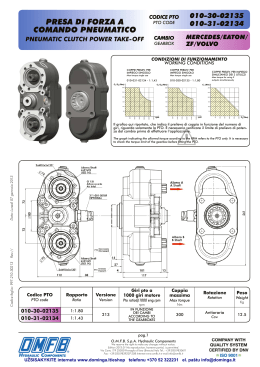
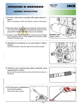
ISTRUZIONI DI MONTAGGIO
KIT INNESTO PTO
CODICE KIT
KIT CODE
KIT ASSEMBLY INSTRUCTIONS
FOR PTO CLUTCHES
301-101-509
ZF AS-TRONIC
ZF EUROTRONIC 2
Il cambio ZF ‘AS TRONIC’ ed ‘EUROTRONIC 2’ sono asserviti da una centralina elettronica che gestisce
anche la presa di forza. Il nostro kit innesto PTO, dal montaggio molto semplice e pratico in quanto completamente preassemblato, è stato studiato per interfacciarsi con l’impianto originale del veicolo, consentendo l’azionamento delle prese di forza. L’affidabilità è garantita dalla qualità dei componenti utilizzati.
L’azionamento della P.T.O. è garantito anche in caso di guasto dell’elettrovalvola, grazie alla possibilità di
intervenire manualmente sul dispositivo di emergeza.
ZF ‘AS TRONIC’ and ‘EUROTRONIC 2’ gearboxes have an electronic CDI which manages the power takeoff. The plant interfaces with
the existing vehicle plant, enabling the CDI. Assembly is quick and easy due to the pre-assembled kit. Reliability is guaranteed by the
quality of parts etc. Power takeoff can also be supplied by emergency manual operation.
COMPONENTI IMPIANTO
Data: Lunedì 04 giugno 2012
PLANT COMPONENTS
IMPIANTO ELETTRICO
Codice foglio: 997-009-00367 Rev: AB
ELECTRIC PLANT
")!.#/7()4%
-!22/.%"2/7.
.#
.#
")!.#/7()4%
-!22/.%"2/7.
")!.#/7()4%
#!6/-!22/.%
#!",%"2/7.
#!6/7()4%
#!",%7()4%
pag.1
O.M.F.B. S.p.A. Hydraulic Components
We reserve the right to make any changes without notice.
Edition 2006.05 No reproduction, however partial, is permitted.
Via Cave, 7/9 25050 Provaglio d’Iseo (Brescia) Italy Tel.: +39.030.9830611
Fax: +39.030.9839207-208 Internet:www.omfb.it e-mail:[email protected]
ZF AS-TRONIC
ZF EUROTRONIC 2
KIT INNESTO PTO PER IVECO STRALIS
KIT FOR PTO CLUTCHES FOR IVECO STRALIS
301-101-509
• Fissare l’elettrovalvola all’interno
del longerone destro del telaio • Fix the solenoid valve inside the right
in prossimità della presa di forza side of the chassis nearby the PTO,
ensuring an easy access to the emergarantendo la facilità di accesso gency control.
al comando di emergenza;
• Connect up the pneumatic plant as
• Collegare l’impianto pneumati- shown in the drawing.
co come indicato in figura
FILTRO
FILTER
MONTARE L’ELETTROVALVOLA
CON IL FILTRO RIVOLTO
VERSO IL BASSO.
IN
FIT THE SOLENOID
VALVE WITH THE FILTER
FACING THE GROUND.
OUT
pag.2
O.M.F.B. S.p.A. Hydraulic Components
We reserve the right to make any changes without notice.
Edition 2006.05 No reproduction, however partial, is permitted.
Via Cave, 7/9 25050 Provaglio d’Iseo (Brescia) Italy Tel.: +39.030.9830611
Fax: +39.030.9839207-208 Internet:www.omfb.it e-mail:[email protected]
Codice foglio: 997-009-00367 Rev: AB
• Far scorrere l’impianto (lato faston) attraverso il passaggio nel
longherone destro del telaio, • Slide the plant through the gap in the
quindi posizionarlo seguendo il faston side of the frame side member
and move it as shown in figures 2 and
percorso indicato in fig.2 e 3 fino
3 to the junction box (fig.1)
alla scatola connessioni fig.1
• Secure the eyelet (brown wire) to
• Fissare l’occhiello (filo marrone) the vehicle earth inside the right side
alla massa del veicolo posizio- member of the frame (fig.2)
nata all’interno del longherone
destro fig.2
Data: Lunedì 04 giugno 2012
Rimuovere il carter di protezione
Remove the protecting cover at the back
posizionato nel retro cabina lato
of the passenger side of the cabin
passeggero
ZF AS-TRONIC
ZF EUROTRONIC 2
KIT INNESTO PTO PER IVECO STRALIS
301-101-509
KIT FOR PTO CLUTCHES FOR IVECO STRALIS
PROCEDURE DI CABLAGGIO/WIRING STEPS:
A) Per As-Tronic / For As-Tronic
Individuare il connettore da utilizFind the connector to use for the two
zare per l’inserimento dei due fafastons.
ston.
FILO
BIANCO 0131 (SPINA 17)
0131 WHITE WIRE (CONNECTOR 17)
Codice foglio: 997-009-00367 Rev: AB
Data: Lunedì 04 giugno 2012
FILO
BIANCO 9131 (SPINA 14)
9131 WHITE WIRE (CONNECTOR 14)
• Rimuovere i due fermi indicati
dalle frecce;
• Sfilare il connettore;
• Rimuovere i 2 tappi in corrispondenza delle sedi dei faston da
utilizzare;
• Infilare i due faston;
• Reinserire il connettore nella
propria sede fissandolo con i due
fermi precedentemente rimossi.
• Remove the two stops shown by the
arrows.
• Remove the connector.
• Remove the 2 plugs from the faston
housing.
• Fit the fastons.
• Replace the connector and secure
with the two stops.
B) Per EUROTRONIC 2 / For EUROTRONIC 2
• Il connettore da utilizzare è lo
stesso della configurazione pre- • The connector to use is the same the
previous configuration. (See picture
cedente (vedi foto 5);
5).
• Togliere il tappo della sede ri• Remove the plug from the seat by remuovendo i due fermi di colore
moving the two red stops.
rosso;
Pos.8
FILO BIANCO 9131 PTO 2
9131 WHITE WIRE PTO 2
Pos. 17
FILO BIANCO
9131 PTO 1
9131 WHITE
WIRE PTO 1
Pos. 13-14
FILO BIANCO 0131 SPIE PTO 1-2
0131 WHITE WIRE LAMP PTO 1-2
• Infilare i due faston come in figura nel connettore incluso nel kit.
NB: La posizione del filo bianco
è utilizzabile indifferentemente in
entrambe le posizioni.
• Tappare i fori non utilizzati con i
gommoni in dotazione.
• Inserire il connettore nella propria sede fissandolo con i due
fermi precedentemente rimossi.
• Fit the fastons into the connector sup-
plied with the kit as shown in the
picture.
PS: the white wire can be placed in both
positions.
• Plug the hole with the rubber caps
supplied.
• Fit the connector in the proper seat
and secure with the two stops previously removed.
pag.3
O.M.F.B. S.p.A. Hydraulic Components
We reserve the right to make any changes without notice.
Edition 2006.05 No reproduction, however partial, is permitted.
Via Cave, 7/9 25050 Provaglio d’Iseo (Brescia) Italy Tel.: +39.030.9830611
Fax: +39.030.9839207-208 Internet:www.omfb.it e-mail:[email protected]
ZF AS-TRONIC
ZF EUROTRONIC 2
KIT INNESTO PTO PER IVECO STRALIS
KIT FOR PTO CLUTCHES FOR IVECO STRALIS
301-101-509
• Rimuovere i copriforo tra leva
freno a mano e cloche cam• Remove the hole cap between the
bio;
• Individuare i connettori origi- hand brake and gearbox.
nali per il comando delle PTO • Find the original connectors for the
control of PTO 1 and 2 as follows.
1 e 2 così identificati:
PTO 1
PTO 1
wire 0131
filo 0131
PTO 2
PTO 2
wire 0132
filo 0132
• Use the connector for PTO 1 and
• Utilizzare il connettore per the safety key provided in the kit
PTO1 e utilizzare il tasto di si- (Cod. IVECO 99456502)
curezza fornito nel kit.
(Cod. IVECO 99456502)
NOTA: ATTIVAZIONE MANUALE DEL COMANDO DI EMERGENZA
CONTROL OF OVERRIDE EMERGENCY SYSTEM
Ruotare in posizione 1 per aprire.
Turn in position 1 to open it.
Chiuso/Closed
Aperto/Open
pag.4
O.M.F.B. S.p.A. Hydraulic Components
We reserve the right to make any changes without notice.
Edition 2006.05 No reproduction, however partial, is permitted.
Via Cave, 7/9 25050 Provaglio d’Iseo (Brescia) Italy Tel.: +39.030.9830611
Fax: +39.030.9839207-208 Internet:www.omfb.it e-mail:[email protected]
Codice foglio: 997-009-00367 Rev: AB
Data: Lunedì 04 giugno 2012
La programmazione della centralina elettronica del veicolo The electronic CDI must be programdeve essere effettuata presso un med by an authorized Iveco dealer,
concessionario autorizzato IVE- on PTO 1.
CO, su PTO 1.
Scaricare