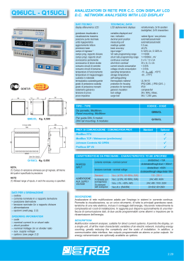
CONVERTITORE PROGRAMMABILE, FINO A 12 USCITE
PROGRAMMABLE TRANSDUCER, UP TO 12 OUTPUTS
MCUU...
DATI TECNICI
tipo di misura
precisione base
tensione nominale
corrente nominale
campo di ingresso (1)
frequenza di riferimento
campo prog. rapporto TV
campo prog. rapporto TA
sovraccarico permanente
sovraccarico di breve durata
consumo circuiti corrente/tensione
ondulazione residua
tempo di risposta
programmabilità
temperatura di funzionamento
temperatura di magazzinaggio
custodia in materiale
termoplastico autoestinguente
isolamento galvanico
TECHNICAL DATA
measuring type
basic accuracy
nominal voltage
nominal current
specified input range (1)
reference frequency
VT ratio programming range
CT ratio programming range
continuous overload
short-term overload
current/voltage circuits consumption
residual ripple
response time
programmability
operating temperature
storage temperature
self estinguishing
thermoplastic material
galvanic insulation
tensione di prova
test voltage
prova impulsiva
conforme a
surge test
according to
CODICE - CODE
DIMENSIONI (Moduli DIN)
DIMENSIONS (DIN modules)
Kg. 0,550
N° USCITE
N° OUTPUTS
TRMS
±0.5% (±0.2%opz./opt.)
100 ÷ 400V
1 ÷ 5A
20÷480V, 5-120% (1)
50/ 60Hz
1÷10000
1÷10000
2 x In; 1.2 x Un
20 x In; 2 x Un
< 0.5VA
< 0.1% p.p.
100ms. (300ms.-12 outs)
completa (vedere testo) - full (see text)
-10…+23…+50°C
-30…+70°C
UL 94-V0
alim./ingressi/uscite
p. supply/inputs/outputs
2kV, 50Hz, 60sec.(alim./p. supply)
2kV, 50Hz, 60sec.(ingr.-uscite/in-outs)
500V, 50Hz, 60sec.(tra moduli/among units)
5kV, 1.2/50 µsec.
EN 60688
MCUU2
MCUU4
MCUU6
MCUU8
MCUU12
6+.3
6+3
6+3+3
6+3+3
6+3+3+3
2
4
6
8
12
MODULO BASE - MAIN UNIT
Configurabili in campo - On site settable
0-1mA (15kΩ); 0-5mA (3kΩ); 0-10mA (1,5kΩ);
0-20mA (750Ω); 4÷20mA (750Ω);
±1mA (15kΩ); ±5mA (3kΩ); ±10mA (1,5kΩ); ±20mA (750Ω);
USCITE
OUTPUTS
0-1V (>2kΩ); 0-10V (>2kΩ); ±1V (>2kΩ); ±10V (>2kΩ); 2÷10V (>2kΩ)
TEMPO DI RISPOSTA
RESPONSE TIME
100msec
100msec
200msec
200msec
300msec
CARATTERISTICHE DA PRECISARE - CHARACTERISTICS TO BE SPECIFIED
Standard
Kg. 0,330
MODULO USCITE ANALOGICHE
ANALOG OUTPUTS UNIT
NOTE:
(1) Campo di variazione ammesso per gli ingressi, all’interno del quale
è specificata la precisione
NOTE:
(1) Allowed range of inputs, in which the accuracy is specified.
DATI PER L’ORDINAZIONE
– codice
– alimentazione
– opzioni (vedi pag. 6.2)
ORDERING INFORMATION
– code
– power supply
– options (see page 6.2)
6.8
ALIMENTAZIONE
AUX. SUPPLY
VOLTAGE
A richiesta con
sovrapprezzo
On demand
with extraprice
115 - 230 Va.c. (±10%, 45÷65Hz, 6VA)
24V; 48V; 400Va.c. (±10%, 45÷65Hz, 6VA)
24V; 48V; 110V; 220Vd.c. (-15...+20%, 6W)
20÷60V; 80÷260Va.c./d.c. (6VA/6W)
DESCRIZIONE
Convertitore multifunzione adatto per l’impiego in sistemi trifase a tre o quattro fili con carico squilibrato, anche in presenza di forme d’onda distorte. Esegue la misura di tutte le principali grandezze caratteristiche di una rete elettrica, inclusi i conteggi di energia attiva e
reattiva, riducendo notevolmente la complessità ed i costi di installazione. Ognuna delle
2÷12 uscite analogiche può essere programmata in campo, rendendo possibile la configurazione del trasduttore in funzione delle diverse esigenze di misura. In aggiunta può
disporre opzionalmente di una interfaccia RS485 con protocollo ModBus, di uscite di allarme e di uscite impulsive per la ritrasmissione delle energie.
DESCRIPTION
Multifunction transducer, suitable for three or four wires three-phase systems with unbalanced load, even with distorted waveforms. It performs the measurement of all main characteristic variables of an electric network, including active and reactive energy counting,
greatly reducing the complexity and the costs of installation. Each one of the 2÷12 analog
outputs can be programmed on site, this permits the configuration of the transducer according to the application requirements. In addition, an RS485 interface with ModBus protocol,
alarms outputs and pulse outputs for energy retransmission are optionally available as
options.
MCUU...
CONVERTITORE PROGRAMMABILE, FINO A 12 USCITE
PROGRAMMABLE TRANSDUCER, UP TO 12 OUTPUTS
Dati tecnici aggiuntivi
conteggio delle energie
conteggio massimo
classe di precisione
bidirezionalità
uscite allarme
ritardo di attivazione
programmabilità
Additional technical Data
energy counting
kWh e/and kVarh
maximum counting
99999999 GWh/GVArh
accuracy class
2 (kWh), 3 (kVArh)
bidirectionality
si / yes (kWh+ / kWh-)
alarm outputs
Photo-mos 100V e 250V, 100mA
activation delay setting
programm. 0...99 sec.
programmability
variabile, valore, direzione/
variable, value, direction
uscite impulsive (su unità base) pulse outputs (on the main unit) programmabile in alternativa
agli allarmi / programmable as
alternative to alarms
programmabilità
programmability
peso impulso/pulse value
durata impulso
pulse duration
30...1000 msec.
interfaccia seriale
serial interface
RS485 isolata/insulated
protocollo di comunicazione
communication protocol
ModBus RTU
velocità (bps)
speed (bps)
9600/19200
parametri di comunicazione
communication parameters
1,8,N,2/1,8,E,1/1,8,O,1
campo di indirizzamento
addressing range
1…247 programm.
GRANDEZZE MISURATE - MEASURED VARIABLES
Grandezze di fase
Phasevariables
Grandezze
di sistema
System variables
Corrente di linea / Line current
L1, L2, L3
––
Tensione di fase L-N / Star voltage L-N
L1, L2, L3
––
Tensione concatenata L-L / Delta voltage L-L
L1, L2, L3
––
––
somma / sum
TIPO - TYPE
Potenza attiva / Active power
Potenza reattiva / Reactive power
Fattore di potenza (cosφ) / Power factor (cosφ)
Frequenza / Frequency
Corrente media / Average current
Potenza attiva media. / Average active power
Max. corrente media / Max. average current
––
somma / sum
L1, L2, L3
media / average
L1
––
L1, L2, L3
––
––
somma / sum
L1, L2, L3
––
Punta massima (kW) / Max. demand (kW)
––
somma / sum
Energia attiva (kWh+) / active energy (kWh+)
––
somma / sum
Energia reattiva (kVAR+) / reactive energy (kVARh+)
––
somma / sum
NOTE
I valori della corrente e della potenza media sono calcolati in base ad un tempo (periodo di integrazione) programmabile tra 1 e 60 minuti.
USCITE ANALOGICHE PROGRAMMABILI
Ogni singola uscita analogica può essere individualmente e completamente configurata in
campo; la selezione del tipo di uscita (corrente o tensione c.c.) viene effettuata tramite dip-switches collocati sul retro del modulo (Fig. 1), mentre tutte le altre impostazioni vengono effettuate direttamente sul pannello frontale dell’unità base.
Esse sono:
- Valore nominale dell’uscita
(es.: 0…+/-1mA, 0…+/-5mA, 0…+/-10mA, 0…+/-20mA, 4…20mA; 0…+/-1V,
0…+/-10V, 2…10V, etc., in accordo con il tipo precedentemente selezionato)
- Misura da associare all’uscita, tra quelle effettuate dall’unità base
(es. tensioni, correnti, potenze, fattori di potenza, etc.)
- Valori di inizio e fondo scala dell’uscita
(es. -25…0…100kW = 4…20mA; 45…50…55Hz = -1…0…+1V; etc.)
TRMS
La misura delle grandezze di base (tensioni e correnti) viene eseguita con il metodo del campionamento, che per sua natura consente il calcolo corretto del vero valore efficace (TRMS) anche in presenza
di forme d’onda distorte, sempre più frequenti negli impianti elettrici moderni.
CONNESSIONE TRA MODULO BASE E MODULI USCITE ANALOGICHE
WIRING CONNECTION BETWEEN
MAIN UNIT AND ANALOG OUTPUTS UNITS
NOTES
Average current and average active power values are calculated considering a time period (integration
period) programmable between 1 and 60 minutes.
PROGRAMMABLE ANALOGUE OUTPUTS
Each single analogue output can be individually and fully configured on site; output type selection (current or voltage d.c.) is made by dip-switches located on the bottom of the unit (Fig. 1),
while all other settings are feasible directly from the front panel of the main unit.
They are:
- Nominal value of the output
(i.e. 0…+/-1mA, 0…+/-5mA, 0…+/-10mA, 0…+/-20mA, 4…20mA; 0…+/-1V,
0…+/-10V, 2…10V and so on, according to the type previously selected)
- Variable to be represented by the output, among all available in the main unit
(i.e. voltages, currents, powers, power factors and so on)
- Start and end scale values of the output
(i.e. -25…0…100kW = 4…20mA; 45…50…55Hz = -1…0…+1V and so on)
TRMS
The measurement of the main variables (currents and voltages) is performed with the sampling method,
which, in its own nature, permits the correct computation of the TRMS even in presence of distorted
waveforms, which are more and more usual in modern electrical installations.
6.9
MCUU...
CONVERTITORE PROGRAMMABILE, FINO A 12 USCITE
PROGRAMMABLE TRANSDUCER, UP TO 12 OUTPUTS
MISURE ADDIZIONALI E CONTEGGIO DELLE ENERGIE
Oltre alla misura di tutte le principali grandezze caratteristiche della rete elettrica, questi
strumenti calcolano e forniscono anche delle informazioni addizionali molto utili per la
verifica del buon andamento dell’impianto, per la valutazione dei prelievi energetici e per
la prevenzione del superamento dei limiti contrattuali; esse sono:
- il valore medio della corrente (corrente termica), calcolato in un intervallo di tempo programmabile
- il valore massimo raggiunto dalla corrente termica
- il valore medio della potenza attiva, calcolato in un intervallo di tempo programmabile
- la punta massima (il valore massimo raggiunto dalla potenza attiva media)
- l’energia attiva (+/- kWh)
- l’energia reattiva (+/- kVArh)
Il valore medio della corrente ed il valore massimo raggiunto dalla corrente media simulano rispettivamente l’indice nero e quello rosso di un amperometro a bimetallo.
Quando viene a mancare l’alimentazione dello strumento, i conteggi delle energie vengono automaticamente salvati in una memoria non volatile; il tempo di ritenzione dei dati
è maggiore di 20 anni e non vi sono batterie da sostituire.
USCITE DI ALLARME ED USCITE IMPULSIVE
Per ogni modulo, sia base che uscite analogiche, sono disponibili due uscite di allarme
(opzionali), utilizzabili per controllare l’andamento di specifiche grandezze misurate. La
loro programmazione consente di stabilire la modalità di funzionamento (di minima o di
massima oppure, solo sul modulo base, come watch-dog),quale è la variabile controllata, il suo livello di soglia e il ritardo di intervento. Nel caso in cui le variabili controllate
siano delle tensioni o delle correnti, l’allarme agisce in modalità trifase, cioè interviene se
una qualsiasi delle tre fasi supera il livello di soglia prestabilito. In tutti gli altri casi invece la grandezza controllata è quella di sistema (somma o media delle singole fasi).
In alternativa, tramite le due uscite del modulo base, è possibile ritrasmettere i conteggi
delle energie ad unità remote quali contaimpulsi esterni, PLC, etc.
Il peso dell’impulso è programmabile in modo diretto, es. 1 impulso = …kWh, in modo
indipendente tra energia attiva e reattiva.
INTERFACCIA SERIALE RS485
L’interfaccia seriale RS485 (opzionale), consente di integrare lo strumento in sistemi di
supervisione o di gestione dell’energia. Il protocollo utilizzato è il ModBus, in modalità
RTU. Su una stessa linea RS485 possono essere collegati fino a 32 strumenti (128 con
l’opzione 1/4 unit load, o 247 utilizzando opportuni amplificatori di linea), coprendo una
distanza massima di 1200 metri.
IMPOSTAZIONE DEI RAPPORTI TA E TV
L’impostazione dei rapporti di trasformazione dei TA e dei TV si effettua in modo molto
semplice, programmando i valori dei primari e dei secondari così come sono riportati
sulle targhette dei trasformatori stessi.
MODULO BASE / MAIN UNIT
per linea trifase a tre fili
for three-phase three wires system
MODULO BASE / MAIN UNIT
per linea trifase a quattro fili
for three-phase four wires system
ADDITIONAL VARIABLES AND ENERGY COUNTING
In addition to the measurement of the main characteristics variables of the electric network, these instruments calculate and provide additional information very useful to verify
the good behaviour of the system, to evaluate the energy withdrawing and to prevent
exceeding the contractual limits; they are:
- the average current (thermal current) calculated in a programmable time interval
- the maximum value reached by the thermal current
- the average active power, calculated in a programmable time interval
- the maximum demand (maximum value reached by the average active power)
- the active energy (+/- kWh)
- the reactive energy (+/- kVArh)
The average current indication and the maximum value reached by the average current
simulate the black and the red pointers respectively of a bimetal ammeter.
In case of aux power loss, the content of the energy registers is automatically saved in a
non volatile memory; the data retention time is more than 20 years and there are not batteries to be replaced.
ALARM AND PULSE OUTPUTS
For each module, either main unit or analog outputs units, two alarm outputs (optional)
are available to control the behaviour of specific measured variables. It is possible to
define the functioning mode (as minimum or maximum level or, just for the main unit, as
a watch-dog), the controlled variable type, the alarm value and the activation delay. When
monitoring currents or voltages, the alarms work in three-phase mode, this means that
they activate the output relays when one of the three phases crosses the set point; in all
other cases the controlled variable is the one of the system (sum or average of the different phases).
As alternative it is possible to retransmit, via the two outputs of the main unit, the energy
counting to remote units as external pulse counters, PLC and so on. The pulse value is
directly programmable i.e. 1 pulse = …kWh, independently for active and reactive energy.
RS485 SERIAL INTERFACE
The serial interface RS485 (optional) permits to integrate the instrument in supervision
and/or energy management systems. The protocol is the ModBus in RTU mode.
Up to 32 instruments (128 with the 1/4 unit load option, or 247 using suitable line amplifiers) can be connected on the same RS485 line, at a maximum distance of 1200 meters
(4000 FT).
MODULO USCITE ANALOGICHE
ANALOG OUTPUTS UNIT
6.10
CT AND VT RATIOS SETTING
Setting of the CT and VT ratios is performed in a very simple way, programming the primary and secondary values exactly as they are written on the transformer label.
Scaricare