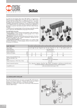
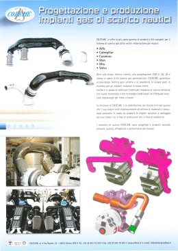
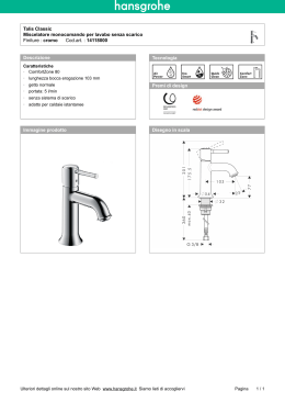
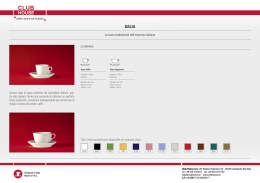
Serie FRL
Avviatore progressivo con scarico rapido
Soft start valve with quick exhaust
T060
Taglia 1
Size 1
Codice
Code
MisuraFiletto Comando
Size Thread
Drive
APE 1
3/8
EP
APE 2
3/8
EP
APE 2
1/2
EP
APE 3
3/4
EP
APE 3
1”
EP:
Elettropneumatico - Electropneumatic
EP
NB: STANDARD SENZA SOLENOIDE VEDI PAG. 17.48 - STANDARD WITHOUT SOLENOID SEE PAG. 17.48
NB: L’avviatore progressivo non può essere utilizzato in atmosfera
potenzialmente esplosiva secondo la Direttiva ATEX.
NB: According to the Directive ATEX soft start valves cannot be used in
potentially explosive environment.
Taglia 2 e 3
Size 2 and 3
Dimensioni - Dimensions
D
A
J
FRL 1
C
L
K
W
E
B
N
P
O
F
A
B
C
D
W
E
F
J
K
L
N
P
O
118.5
126.5
45
115
1/8 - 1/4 - 3/8
21
22.5
97
26
ØxM5
73.5
32.5
26
A
FRL_ITA_ING_2014.indd 29
19/05/14 23:15
Serie FRL
FRL 2
A
J
C
P
D
O
F
G
89
142
59
89
1/4 - 3/8 -1/2
27.5
28.5
55.5
55
69
32.5
ØxM5
76.5
32
38.5
106 106 111
131.5
70
100
1/2 - 3/4 -1
32.5
35
55.5
65
79
38
ØxM5
76.5
38.5
45
L
K
W
E
B
N
I
A
B
C
D
W
E
F
G
I
J
K
L
N
O
P
FRL 3
Scheda Materiali - Specifications
4
3
2
5
6
1
1 Corpo in tecnopolimero
2 Gruppo di comando in ottone
3 Vite di regolazione del flusso in ottone
4 Elettropilota
5 Uscita dello scarico rapido
6 Terminale in zama
7 O-Ring in NBR
8 Tappo inferiore in ottone
9 Otturatore in ottone con O-Ring integrata
10 Molla premiotturatore in acciaio inox
11 Elemento di fissaggio / distanziale
1 Technopolymeric Body
2 Brass Impulse group
3 Brass Adjusting screw
4 Electronic pilot
5 Exit of the quick exhaust
6 Zamac End part
7 NBR O-ring
8 Brass Lower plug
9 Brass Shutter with integrated O-ring
10 Stainless steel Shutter spring
11 Fixing with distance
7
11
10
9
Dati tecnici - Technical data
ATTACCO FILETTATO / THREADED FASTENING
VITI DI FISSAGGIO / WALL CLAMPING SCREWS
PRESSIONE MAX D’INGRESSO / MAXIMUM INLET PRESSURE
FRL 1
FRL 2
FRL 3
1/4”-3/8”-1/2”
1/4”-3/8”-1/2”
1/2”-3/4”-1”
M5X18
M5X18
M6X20
4-10 bar
4-10 bar
3-10 bar
FLUIDO / FLUID
ATTACCO FILETTATO USCITA SCARICO RAPIDO / FASTENING QUICK EXHAUST
TEMPERATURA / TEMPERATURE
POSIZIONE DI MONTAGGIO / ASSEMBLING POSITION
POSIZIONE IN LINEA / LINE POSITION
ARIA COMPRESSA / COMPRESSED AIR
1/8”
1/4”
Min -10 / Max +50°C a/to 10 bar
VERTICALE / VERTICAL
IN CODA AI COMPONENTI FRL
END OF ALL FRL COMPONENTS
TIPO DI COMANDO / DRIVE SYSTEM
SOLENOIDE / SOLENOID
ELETTROPNEUMATICO / ELECTROPNEUMATIC
24V DC 3W - 220V AC 5VA
4
4
FRL_ITA_ING_2014.indd 30
19/05/14 23:15
Instructions
Istruzioni Tecniche Frl 1-2-3 / Technical Instruction Frl 1-2-3
L’assemblaggio dei componenti della serie FRL deve seguire,
in linea di massima, questo ordine: Valvola sezionatrice,
Filtro, Regolatore, Lubrificatore e Avviatore progressivo.
L’accoppiamento dei componenti deve avvenire facendo
in modo che l’aria fluisca nella direzione indicata dalle
frecce poste sulla superficie superiore dei componenti.
The setting up of the parts has to be done as follows: Put
the plates in the proper places of the bodies. Put the
assembling parts together , making sure that the o-ring are
in their proper seats. Tighten the screws on the plates.
Per l’impostazione della pressione si devono seguire queste indicazioni:
- sollevare la manopola nella posizione di regolazione;
- impostare la pressione voluta sempre in salita;
- premere la manopola nella posizione di blocco.
L’applicazione del manometro deve avvenire manualmente e con l’utilizzo di
sigillanti liquidi.
To regulate the pressure follow these suggestions:
- raise the knob to the regulating position;
- fix up the required pressure always upgrade then press the knob to the block
position.
The manometer has to be assembled manually with the addition of liquid sealant.
L’azionamento della valvola sezionatrice
avviene nelle seguenti fasi: premendo
il pulsante di azionamento 1 si apre il
circuito primario verso l’utilizzo, premendo
il pulsante 2 si chiude il circuito primario
e si mette a scarico quello secondario.
Quest’ultima posizione può essere
bloccata mediante lucchetto.
L’inserimento dell’olio nel lubrificatore
si effettua svitando il tappo posto sulla
superficie superiore oppure smontando la
tazza accertandosi prima che non vi sia
pressione nell’impianto. La regolazione
dell’olio nel circuito si effettua agendo con
un cacciavite sullo spillo e impostando
una goccia di olio ogni 300-600 Nl/min.
The driving of the shut off valve follows these
steps: pressing the start push button 1 you
open the primary circuit towards the use;
pressing the push button 2 you close the
primary circuit and put the secondary one
in exhaust. A padlock can lock this last
operation.
To insert the oil into the lubricator, unscrew the plug on the upper
surface or disassemble the bowl
making sure that no pressure is in the
system. To regulate the oil into the circuit
act the needle with a screwdriver and
adjust 1 oil drop every 300/600NI/min.
4
4
FRL_ITA_ING_2014.indd 14
19/05/14 23:15
Instructions
Il caricamento dell’olio a depressione
consente il riempimento in automatico di
olio nella tazza. Il sistema si attiva mediante
l’azionamento di un pulsante e l’olio
prelevato da un serbatoio posto anche
a quote più basse rispetto al lubrificatore
fluisce nella tazza grazie ad un attacco
G1/4 posto sotto di essa. Il caricamento
deve essere interrotto quando l’olio
raggiunge il livello massimo consentito
corrispondente alle aperture trasparenti
della tazza.
The priming of vacuum permits the automatic filling in the bowl. Pushing the start
button starts the driving of the system.
The oil, collected from a level lower than
lubricator, flows into the bowl thanks to a
fitting G located under the bowl. Stop the
priming when the oil has reached the maximum level allowed. This level corresponds
with the transparent windows in the bowl.
L’avviatore progressivo è un dispositivo
pneumatico che consente di pressurizzare
gradualmente e in modo regolabile gli
impianti pneumatici. Lo scarico rapido
è una funzione integrata presente nel
nostro avviatore progressivo quindi
è possibile interrompere l’afflusso di
aria, interrompendo il segnale elettrico
del pilota, e scaricare rapidamente
l’aria residua nell’impianto di valle
nell’ambiente esterno. La regolazione del
tempo dell’incremento della pressione
avviene mediante la registrazione di
un’apposita vite che interviene sulla
regolazione del flusso. Il comando
di pilotaggio è elettropneumatico: il
funzionamento dell’avviatore progressivo
avviene mediante un impulso elettrico.
L’avviatore progressivo con scarico rapido
va posizionato nella linea dell’impianto
dopo tutti i componenti di trattamento
dell’aria compressa.
The soft start valve is a pneumatic valve
that permits to pressurize gradually and
constantly the pneumatic systems. The
quick exaust is present on our soft starter; by switching off the electrical signal
it stops the air-intake, exhusting
the
remaining
air
downstream.
To
regulate
the
pressure increasing time use a screw.
An electrical impulse gives power to the
starter. Install the starter on the system just
after the components for air treatment.
Lo scarico della condensa Manuale / Semiautomatico é normalmente nella posizione
aperta cioé scarica automaticamente la condensa quando é assente la pressione nella
tazza, premendo la manopola é possibile scaricare la condensa in presenza di pressione,
ruotando la manopola in senso antiorario lo scarico é nella posizione chiusa.
The automatic/semiautomatic condensate exhaust is normally in the open position; i.e. it
exhaust automatically the condensate when there is no pressure inside of the bowl. Pressing
the knob it is possible to exhaust the condensate even if it is on pressure, turning the knob in
anticlockwise sense the exhaust is in the close position.
A
FRL_ITA_ING_2014.indd 15
19/05/14 23:15
Instructions
FISSAGGIO STANDARD.
STANDARD FIXING.
FISSAGGIO CON DISTANZIALE.
FIXING WITH DISTANCE.
Lo scarico di condensa automatico è
disponibile per le misure FRL2 e FRL3 . Il suo
funzionamento è di tipo a galleggiante
cioè scarica la condensa quando
questa raggiunge il livello impostato
indipendentemente dalla pressione di
utilizzo.
The condensate exhaust is available for
the sizes FRL2 and FRL3. It works as a float
that exhausts the condensate when this
reaches the programmed level without
any relation to the pressure used.
L’elemento utilizzato per il fissaggio dei gruppi di trattamento
dell’aria a parete può svolgere la funzione di distanziale:
è sufficiente svitare tale elemento, ruotarlo e riavvitarlo. Il
distanziale permette così il fissaggio dei gruppi di trattamento
dell’aria sulle superfici non perfettamente piane e disconnesse.
The part used to fix the FRL on the wall can be used as a
distance spacer as well. It is enough to unscrew this part, turn
it and screw it again. The distance spacer penits in this way
the fixing of the treatment of compressed air on surfaces not
properly smooth and flat.
Per lo smontaggio della tazza utilizzare
una chiave esagonale a tubo. Le aperture
trasparenti sulla tazza permettono il
controllo del livello della condensa per il
filtro o dell’olio per il lubrificatore.
To disassembly the bowl use an hexagon
tube wrench. The bowl has got trasparent
windows which permit to check the
lubricator oil level or the filter condensate
level.
4
4
FRL_ITA_ING_2014.indd 16
19/05/14 23:15
Scaricare