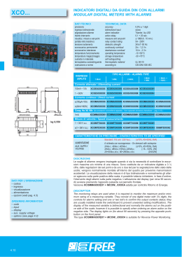
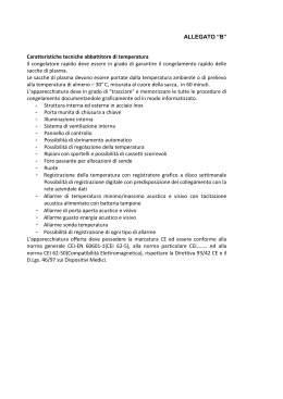
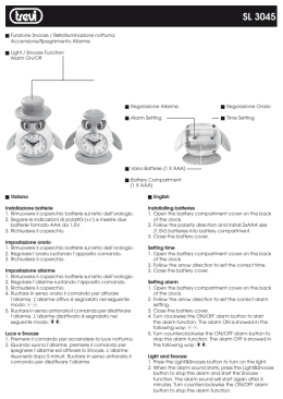
PYTHAGORAS3 Barriera Multi-tecnologia Microonde e infrarosso per protezioni esterne Manuale di Installazione Multi-technology Barrier Microwave and Infrared Installation Manual Edizione / Edition 1.0 20MACIE0197 CIAS Elettronica S.r.l. Ed. 1.0 INDICE 1 DESCRIZIONE ..................................................................................................................................................................................... 3 1.1 2 DESCRIZIONE ...................................................................................................................................................................................... 3 INSTALLAZIONE ................................................................................................................................................................................ 4 2.1 2.2 2.3 2.4 2.5 2.6 2.7 3 MONTAGGIO DELLE UNITÀ .................................................................................................................................................................. 4 NUMERO DI TRATTE............................................................................................................................................................................ 6 AVVERTENZE PER L’INSTALLAZIONE ................................................................................................................................................... 7 CONDIZIONI DEL TERRENO .................................................................................................................................................................. 7 PRESENZA DI OSTACOLI ...................................................................................................................................................................... 7 AMPIEZZA DEI FASCI SENSIBILI A MW ................................................................................................................................................ 8 LUNGHEZZA DELLE ZONE MORTE IN PROSSIMITÀ DEGLI APPARATI ....................................................................................................... 8 COLLEGAMENTI ............................................................................................................................................................................... 9 3.1 MORSETTIERE, CONNETTORI E FUNZIONALITÀ DEI CIRCUITI ................................................................................................................. 9 3.1.1 Circuito di controllo Trasmettitore ....................................................................................................................................... 9 3.1.2 Circuito di controllo Ricevitore .......................................................................................................................................... 11 3.1.3 Circuito Tx e Rx IR ............................................................................................................................................................. 13 3.1.4 Circuito di Interfaccia Trasmettitore .................................................................................................................................. 14 3.1.5 Circuito di Interfaccia Ricevitore ....................................................................................................................................... 15 3.2 COLLEGAMENTO ALL’ALIMENTAZIONE PRINCIPALE ........................................................................................................................... 16 3.2.1 Collegamento all’alimentazione per il Riscaldatore .......................................................................................................... 16 3.2.2 Collegamento all’Alimentazione di Rete............................................................................................................................. 16 3.2.3 Collegamento all’Alimentazione di Riserva (Batteria) ....................................................................................................... 16 3.3 COLLEGAMENTO ALLA CENTRALE ..................................................................................................................................................... 17 3.3.1 Contatti di segnalazione: .................................................................................................................................................... 17 3.3.2 Connessioni per Sincronismo ............................................................................................................................................. 18 3.3.3 Connessioni per Test ........................................................................................................................................................... 18 3.3.4 Connessioni per Stand by ................................................................................................................................................... 18 3.4 LINEA SERIALE RS-485 ................................................................................................................................................................... 19 3.4.1 Interfaccia Linea Seriale RS-485 / 232 ............................................................................................................................... 19 3.4.2 Connessioni per Linea Seriale RS-485 ............................................................................................................................... 19 3.4.3 Configurazione Rete e Rigeneratori di segnale .................................................................................................................. 19 3.5 COLLEGAMENTO DA ACCESSO REMOTO ............................................................................................................................................ 20 4 ALLINEAMENTO E VERIFICA MICROONDA ........................................................................................................................... 21 4.1 ALLINEAMENTO E VERIFICA .............................................................................................................................................................. 21 4.1.1 Operazioni sul Trasmettitore .............................................................................................................................................. 21 4.1.2 Operazioni sul Ricevitore ................................................................................................................................................... 23 4.2 ALLINEAMENTO E VERIFICA CON SOFTWARE ..................................................................................................................................... 29 5 ALLINEAMENTO E VERIFICA INFRAROSSO ........................................................................................................................... 30 5.1 5.2 SELEZIONE CANALI ........................................................................................................................................................................... 30 ALLINEAMENTO OTTICO ................................................................................................................................................................... 32 5.2.1 Descrizione dell’allineamento ottico dei moduli ................................................................................................................ 32 5.3 ALLINEAMENTO ELETTRONICO .......................................................................................................................................................... 33 5.4 SCELTA DELLA MODALITÀ OPERATIVA ............................................................................................................................................... 34 5.5 MODALITÀ OPERATIVE ..................................................................................................................................................................... 35 5.6 TEMPO DI INTERRUZIONE .................................................................................................................................................................. 35 5.7 CONTROLLO DELLA POTENZA ............................................................................................................................................................ 35 5.8 CONTROLLO FINALE .......................................................................................................................................................................... 36 6 MANUTENZIONE E ASSISTENZA ................................................................................................................................................ 37 6.1 6.2 6.3 7 RICERCA GUASTI .............................................................................................................................................................................. 37 KIT ASSISTENZA MW ...................................................................................................................................................................... 37 KIT ASSISTENZA INFRAROSSI............................................................................................................................................................ 37 CARATTERISTICHE ........................................................................................................................................................................ 38 7.1 7.2 CARATTERISTICHE TECNICHE ............................................................................................................................................................ 38 CARATTERISTICHE FUNZIONALI ........................................................................................................................................................ 39 Manuale di Installazione Pagina 1 di 76 PYTHAGORAS 3 CIAS Elettronica S.r.l. Ed. 1.0 INDEX 1 DESCRIPTION ................................................................................................................................................................................... 40 1.1 2 DESCRIPTION .................................................................................................................................................................................... 40 INSTALLATION ................................................................................................................................................................................ 41 2.1 2.2 2.3 2.4 2.5 2.6 2.7 3 MOUNTING OF THE UNIT ................................................................................................................................................................... 41 NUMBER OF ZONES ........................................................................................................................................................................... 43 INSTALLATION ADVICE ..................................................................................................................................................................... 44 GROUND CONDITIONS ....................................................................................................................................................................... 44 OBSTACLES....................................................................................................................................................................................... 44 AMPLITUDE OF THE MW SENSITIVE BEAM ........................................................................................................................................ 45 LENGTH OF THE DEAD ZONES NEAR THE EQUIPMENT ......................................................................................................................... 45 CONNECTIONS ................................................................................................................................................................................. 46 3.1 TERMINALS, CONNECTORS AND CIRCUIT FUNCTIONS .......................................................................................................................... 46 3.1.1 Transmitter Control Circuit ................................................................................................................................................ 46 3.1.2 Receiver Control Circuit ..................................................................................................................................................... 48 3.1.3 IR Transmitter and Receiver Circuit ................................................................................................................................... 50 3.1.4 Transmitter Interface Circuit .............................................................................................................................................. 51 3.1.5 Receiver Interface Circuit ................................................................................................................................................... 52 3.2 CONNECTION TO POWER SUPPLY....................................................................................................................................................... 53 3.2.1 Connection to the Power Supply for Heating ..................................................................................................................... 53 3.2.2 Connection to Main Power Supply ..................................................................................................................................... 53 3.2.3 Connection to Stand-by Power Supply (Battery) ................................................................................................................ 53 3.3 CONNECTION TO THE CONTROL UNIT ................................................................................................................................................ 54 3.3.1 Alarm Contacts: Alarm, Tamper, Fault .............................................................................................................................. 54 3.3.2 Synchronisation Connections ............................................................................................................................................. 55 3.3.3 Test Connections ................................................................................................................................................................. 55 3.3.4 Stand by Connections ......................................................................................................................................................... 55 3.4 RS-485 SERIAL LINE ........................................................................................................................................................................ 56 3.4.1 RS-485 / 232 Serial Line Interface...................................................................................................................................... 56 3.4.2 RS-485Serial Line Connections .......................................................................................................................................... 56 3.4.3 Network Configuration and Signal Regeneration ............................................................................................................... 56 3.5 CONNECTION FOR REMOTE ACCESS................................................................................................................................................... 57 4 MICROWAVE ALIGNMENT AND CONFIGURATION .............................................................................................................. 58 4.1 ALIGNMENT AND CONFIGURATION .................................................................................................................................................... 58 4.1.1 Operations at the TRANSMITTER ...................................................................................................................................... 58 4.1.2 Operations at the Receiver .................................................................................................................................................. 60 4.2 ADJUSTMENT AND TESTING WITH SOFTWARE .................................................................................................................................... 66 5 INFRARED ALIGNMENT AND CONFIGURATION ................................................................................................................... 67 5.1 5.2 CHANNEL SELECTION ........................................................................................................................................................................ 67 OPTICAL ALIGNMENT........................................................................................................................................................................ 69 5.2.1 Description of optical alignment of a module ..................................................................................................................... 69 5.3 ELECTRONIC ALIGNMENT.................................................................................................................................................................. 70 5.4 SELECTION OF OPERATING MODE...................................................................................................................................................... 71 5.5 OPERATING MODE ............................................................................................................................................................................ 72 5.6 INTERRUPTION TIME ......................................................................................................................................................................... 72 5.7 POWER CONTROL ............................................................................................................................................................................. 72 5.8 FINAL CHECKS .................................................................................................................................................................................. 73 6 MAINTENANCE AND SERVICE .................................................................................................................................................... 74 6.1 6.2 6.3 7 FAULT FINDING ................................................................................................................................................................................ 74 MW SERVICE KIT ............................................................................................................................................................................ 74 IR SERVICE KIT ............................................................................................................................................................................... 74 CHARACTERISTICS ........................................................................................................................................................................ 75 7.1 7.2 TECHNICAL CHARACTERISTICS .......................................................................................................................................................... 75 FUNCTIONAL CHARACTERISTICS........................................................................................................................................................ 76 Manuale di Installazione Pagina 2 di 76 PYTHAGORAS 3 CIAS Elettronica S.r.l. Ed. 1.0 1 DESCRIZIONE 1.1 Descrizione PYTHAGORAS3 è una barriera multi tecnologia per protezioni volumetriche perimetrali esterne. La barriera è in grado di rilevare la presenza di un corpo che si muove all’interno di un campo sensibile instauratosi tra il Trasmettitore (TX) e il Ricevitore (RX). I segnali ricevuti dai singoli rivelatori, vengono analizzati e valutati mediante un microprocessore secondo modelli comportamentali (Analisi con logica Fuzzy), in base allo scenario impostato, e sfruttando le migliori sinergie delle tecnologie impiegate (barriere a Microonda, ad Infrarosso e sensori ad effetto doppler), permettono di raggiungere eccellenti prestazioni nella rilevazione, ed un numero estremamente limitato di falsi allarmi. Inoltre un completo efficiente sistema di test e qualifica sonora consentono una enorme semplicità di installazione e di manutenzione. PYTHAGORAS3 è disponibile con le seguenti portate: - PYTHAGORAS3100 - PYTHAGORAS3160 Portata 100 metri Portata 160 metri Disponibile inoltre con colonne alte 2 metri o 3 metri, in doppia tecnologia (barriera infrarosso e barriera a microonde) o tripla tecnologia (barriera infrarosso, barriera microonde e doppler microonde su ogni colonna) Manuale di Installazione Pagina 3 di 76 PYTHAGORAS 3 CIAS Elettronica S.r.l. Ed. 1.0 2 INSTALLAZIONE 2.1 Montaggio delle unità Per il montaggio delle due unità (TX e RX) fissare la base di sostegno a terra. Aprire ogni singola colonna partendo dal coperchio superiore. Rimuovere le viti con l’aiuto di un cacciavite. Estrarre la calotta. Sollevare leggermente il cover dall’estremità della colonna da cui è stato appena rimosso il coperchio. Scorrere con le mani tra cover e parte metallica lungo tutta la colonna. Una volta raggiunta l’altra estremità della colonna, sollevare completamente il cover. Fig. 1a Fig. 1b Fig .1c Fig .1d Posizionare coperchio inferiore sopra la base, inserire la colonna nell’apposita spina dopo aver posizionato la staffa a L di bloccaggio e fissare il tutto utilizzando le viti in dotazione. Fig .1e Fig .1f Fig .1g Fig .1h Manuale di Installazione Pagina 4 di 76 PYTHAGORAS 3 CIAS Elettronica S.r.l. Ed. 1.0 Nella parte superiore di ciascuna colonna sono presenti due interruttori (tamper) in serie. Quello laterale segnala la rimozione del coperchio superiore. Quello centrale segnala invece la pressione sul coperchio ed è quindi indicato per rivelare tentativi di scavalcamento. Interruttore tamper per segnalazione antiscavalcamento attraverso pressione su coperchio superiore Interruttore tamper per segnalazione rimozione coperchio superiore Figura 1i Manuale di Installazione Pagina 5 di 76 PYTHAGORAS 3 CIAS Elettronica S.r.l. Ed. 1.0 2.2 Numero di Tratte Dovendo progettare la protezione con barriere volumetriche di un perimetro chiuso, oltre alle normali considerazioni di suddivisione del perimetro in un certo numero di tratte che tengano conto delle necessità gestionali dell'intero impianto, occorre ricordare che è sempre preferibile installare un numero di tratte pari. Questo perché in un perimetro chiuso formato da un numero di tratte dispari si forma un incrocio dove sono presenti un trasmettitore ed un ricevitore i quali potrebbero interferire tra di loro. Nella figura 2a) l’angolo tra le due teste Tx ed Rx è corretto, ma le due teste sono molto vicine ed il trasmettitore corrispondente al ricevitore posto in questo angolo è molto lontano. Nel caso di figura 2d) le due teste Tx ed Rx formano un angolo maggiore di 90° e ciò non è corretto, queste due teste inoltre sono molto vicine l’una all’altra. Fig.2a ERRATO CORRETTO ERRATO Fig.2d CORRETTO Fig.2e CORRETTO Fig.2f Fig.2b Fig.2c Manuale di Installazione CORRETTO Pagina 6 di 76 PYTHAGORAS 3 CIAS Elettronica S.r.l. Ed. 1.0 2.3 Avvertenze per l’Installazione Per una corretta installazione delle barriere infrarosso, è necessario attenersi alle seguenti regole: Non posizionare i ricevitori in modo tale che la luce solare, diretta o riflessa, possa raggiungerli. Infatti se la luce solare, colpisse direttamente o per riflessione i ricevitori, potrebbero manifestarsi falsi allarmi. Non posizionare la barriera infrarosso accostata a superfici altamente riflettenti, quali pareti bianche o addirittura vetrate, potrebbero, in questo caso, verificarsi fenomeni di insensibilità della barriera (difficoltà a generare un allarme). Non posizionare la barriera infrarosso su supporti meccanicamente instabili, quali recinzioni che possono muoversi, pali male ancorati, in questi casi, potrebbero verificarsi disallineamenti della barriera con conseguente generazione di falsi allarmi. 2.4 Condizioni del Terreno E' sconsigliabile installare l'apparato lungo tratti dove vi siano: erba alta (maggiore di 10 cm), stagni, corsi d'acqua in senso longitudinale ed in generale tutti quei tipi di terreni la cui conformazione sia rapidamente variabile. 2.5 Presenza di Ostacoli Le recinzioni, se metalliche e pertanto molto riflettenti, possono causare diversi problemi di riflessione della microonda, è quindi necessario adottare alcuni accorgimenti: - la recinzione deve essere accuratamente fissata, in modo che il vento non ne provochi il movimento; - dove possibile la tratta non deve essere installata in parallelo alla recinzione, è necessario creare un angolo rispetto ad essa; - nel caso in cui il fascio sensibile debba essere delimitato lateralmente da due reti metalliche, è consigliabile che il corridoio tra esse non sia inferiore ai 5 m. in quanto il loro movimento potrebbe creare dei disturbi. Occorre notare che utilizzando uno degli scenari “AND” successivamente descritti al capitolo 4, Pythagoras3 può essere installato anche in corridoi di dimensioni inferiori a 5 m. e anche parallelamente a recinzioni non ben fissate. - recinzioni metalliche poste dietro gli apparati possono provocare talvolta distorsioni del fascio sensibile. Gli alberi, le siepi, i cespugli, la vegetazione in genere richiede una grande attenzione qualora ve ne sia in prossimità o entro i fasci di protezione. Questi ostacoli sono elementi variabili sia come dimensione che come posizione, possono infatti crescere ed essere mossi dal vento. Pertanto è sconsigliabile tollerare la presenza di detti ostacoli entro le tratte di protezione. E’ possibile tollerarne la presenza solo a patto che la loro crescita venga limitata mediante una metodica manutenzione e che il loro movimento venga inibito mediante barriere di contenimento. All’interno del fascio di protezione, è altresì tollerabile la presenza di tubi, pali ed ostacoli vari (illuminazione, camini, ecc) purché non presentino dimensioni eccessive all’interno dei lobi di protezione. Questi infatti sono la causa di Zone d’Ombra non protette e di Zone di Ipersensibilità, fonti di falsi allarmi. Manuale di Installazione Pagina 7 di 76 PYTHAGORAS 3 CIAS Elettronica S.r.l. Ed. 1.0 2.6 Ampiezza dei Fasci Sensibili a MW L'ampiezza del Campo Sensibile è in funzione dalla regolazione di sensibilità impostata. Le figure seguenti ci forniscono la dimensione a metà tratta del Fascio Sensibile, in funzione della lunghezza della tratta, nel caso di sensibilità massima e minima. 20 Diametro zona sensibile 16 a metà tratta [m] 18 Sensibilità Massima (”F”) 14 12 10 8 Sensibilità minima (”0”) 6 4 Lunghezza della tratta [m] 2 20 40 60 80 100 120 140 160 180 200 220 Figura 3 Larghezza della zona sensibile a metà tratta per PYTHAGORAS3 100-160 (campo libero) 2.7 Lunghezza delle Zone Morte in prossimità degli apparati La lunghezza delle Zone Morte in prossimità degli apparati è in funzione sia della distanza dell'apparato stesso dal suolo, sia della sensibilità impostata sul Ricevitore (figura 4). L’Altezza consigliata per installazioni standard è di 80 cm circa, compatibilmente con le esigenze impiantistiche. La misura è da considerarsi tra il suolo e il centro dell'antenna. Con una sensibilità media, la distanza minima consigliata per effettuare l’Incrocio è di 3,5 m. 100 Altezza dal suolo 90 al centro antenna [cm] 80 Sensibilità Massima (”F”) Sensibilità minima (”0”) 100 90 80 70 70 60 60 50 50 40 40 30 30 20 20 10 Lunghezza 10 zona morta [m] 6 1 2 3 4 5 7 8 9 10 Figura 4 Lunghezza della zona morta in prossimità degli apparati in funzione dell’altezza dal centro dell’antenna al suolo per PYTHAGORAS3 Manuale di Installazione Pagina 8 di 76 PYTHAGORAS 3 CIAS Elettronica S.r.l. Ed. 1.0 3 COLLEGAMENTI 3.1 Morsettiere, connettori e Funzionalità dei Circuiti 3.1.1 Circuito di controllo Trasmettitore 1000uF J2 S1 TERMINAZIONE DI LINEA RS 485 OFF ON JP4 J4 SW2 SW1 J3 SW3 LED GUASTO LED TAMPER JP2 LED ON OFF OUT SYNC GND TEST STBY FLT FLT TMP TMP LO LH GND 13,8V MS3 IN SYNC JP1 MS2 Figura 5 Disposizione topografica dei componenti nel circuito di controllo Tx Nelle seguenti tabelle sono indicate le funzioni delle morsettiere presenti sulla scheda PYTHAGORAS3 TX: MORSETTIERA MS 2 TRASMETTITORE Mors. Simbolo 1 TMP 2 TMP 3 FLT 4 FLT 5 STBY 6 TEST 7 GND 8 SYNC Funzione Contatto Relè di Manomissione + Ampolla AMP1 (NC) Contatto Relè di Manomissione + Ampolla AMP1 (NC) Contatto Relè di Guasto (NC) Contatto Relè di Guasto (NC) Non utilizzato Ingresso per Comando TEST (Norm. Aperto da GND) Uscita Ausiliaria di Massa Uscita (Ingresso) del Segnale di Sincronismo, verso (da) Tx Slave (Master) MORSETTIERA MS 3 TRASMETTITORE Pin 1 2 3 4 Simbolo Funzione 13,8V Positivo di alimentazione Convertitore RS 485/232 (+13,8V GND Negativo di alimentazione e riferim. dati LH Linea Alta Dati (+ RS 485) Linea Bassa Dati (-RS 485) LO Manuale di Installazione Pagina 9 di 76 ) PYTHAGORAS 3 CIAS Elettronica S.r.l. Ed. 1.0 CONNETTORE J2 Pin 1 2 3 Simbolo Funzione GND Massa per Oscillatore a MW DRO Collegamento per Oscillatore a MW GND Massa per Oscillatore a MW CONNETTORE J3 Pin 1-2-3-5-8-9-10-1114-15 4 6 7 12 13 Simbolo N.C. 16 +8V GND +13,8 GND +5V OSC TRASMETTITORE Funzione Non Connesso Massa Tensione di Alimentazione (13,8 V ) Massa Tensione di Alimentazione interna (5 V ) Misura Funzionamento Oscillatore (+4V OK, 0 o 8V = NON OK) Tensione di Alimentazione interna (8 V ) CONNETTORE J4 Pin 1 2 3 TRASMETTITORE = TRASMETTITORE Simbolo Funzione GND Collegamento di Massa al Microinterruttore di Manomissione ING Ingresso Microinterruttore di manomissione GND Collegamento di Massa al Microinterruttore di Manomissione SELETTORE CANALI DEL TRASMETTITORE Simbolo SW3 Funzione Commutatore esadecimale per la Selezione dei Canali di Modulazione da 0 a F SELETTORI NUMERO DI TRATTA Simbolo SW2 Selettore delle Decine SW1 Selettore delle Unità Funzione JUMPERS DEL TRASMETTITORE Simbolo JP1 JP2 JP4 Funzione OUT = Modulazione Interna ( il Tx è Master ed il segnale di Sincronismo esce) IN = Modulazione Esterna (il Tx è Slave ed il segnale di sincronismo entra) Esclusione leds di indicazione guasto e manomissione, Terminazione di linea Normalmente OUT ON OFF LEDS DEL TRASMETTITORE Simbolo Indicazione D7 Guasto D3 Manomissione. Manuale di Installazione Pagina 10 di 76 Normalmente ON ON PYTHAGORAS 3 CIAS Elettronica S.r.l. Ed. 1.0 3.1.2 Circuito di controllo Ricevitore 1000uF J2 BZ1 Jp2 OFF J4 SW3 ON SW2 SW4 SW5 SW1 ON S1 Tp FLT MS2 FLT TMP MS3 TMP ALL ALL LO LH GND 13,8V OFF Jp1 LED LED ALLARME LED GUASTO TAMPER Figura 6 Disposizione topografica dei componenti nel circuito di elaborazione Rx Nelle seguenti tabelle sono indicate le funzioni delle morsettiere presenti sulla scheda PYTHAGORAS3 RX: MORSETTIERA MS2 Mors 1 2 3 4 5 6 RICEVITORE Simbolo Funzione ALL Contatto Relè di Allarme (NC) ALL Contatto Relè di Allarme (NC) TMP Contatto Relè di Manomissione + Ampolla AMP1 (NC) TMP Contatto Relè di Manomissione + Ampolla AMP1 (NC) FLT Contatto Relè di Guasto (NC) FLT Contatto Relè di Guasto (NC) MORSETTIERA MS 3 RICEVITORE Mors 1 2 3 4 Simbolo 13,8V GND LH LO Manuale di Installazione Funzione Positivo di alimentazione Convertitore RS 485/232 (+13,8V Negativo di alimentazione e riferim. dati Linea Alta Dati (+ RS 485) Linea Bassa Dati (-RS 485) Pagina 11 di 76 ) PYTHAGORAS 3 CIAS Elettronica S.r.l. Ed. 1.0 CONNETTORE J2 RICEVITORE Simbolo Funzione GND Massa per Rivelatore a Microonde DET Collegamento per Rivelatore a Microonde (Detector) GND Massa per Rivelatore a Microonde Pin 1 2 3 CONNETTORE J3 RICEVITORE Pin Simbolo Funzione 1-2-3-5-8-10-11-13N.C. Non Connesso 15-16 4 GND Massa 6 +13,8 Tensione di Alimentazione (13,8 V ) 7 GND Massa 9 0,2V Segnale Ricevuto 200 mVpp 12 +5V Tensione di Alimentazione Interna (5 V ) 14 VRAG Tensione del Regolatore Automatico di Guadagno CONNETTORE J4 Pin 1 2 3 RICEVITORE Simbolo Funzione GND Collegamento di Massa al Microinterruttore di Manomissione ING Ingresso Microinterruttore di manomissione GND Collegamento di Massa al Microinterruttore di Manomissione Simbolo Jp1 Jp2 JUMPERS DEL RICEVITORE Funzione Esclusione leds di indicazione Allarme, Manomissione e Guasto (D6, D5, D4) Terminazione di linea Simbolo D4 D5 D6 Simbolo S1 Simbolo Tp 3 Tp 4 Tp 10 Manuale di Installazione LEDS DEL RICEVITORE Indicazione Guasto + Allineamento Manomissione + Allineamento Allarme + Allineamento Default ON OFF Default ON ON ON PULSANTE DI ATTIVAZIONE DELLE FUNZIONI Funzione -Attivazione recupero e acquisizione valori in fase di allineamento (con SW1 In posizione 1) - Acquisizione Canale, Valore di Campo e Indicazione della Qualità dell’Allineamento (con SW1 In posizione 2) - Attivazione della indicazione della qualità dell’allineamento (con SW1 In posizione 3) TEST POINTS DEL RICEVITORE Funzione Misura del Segnale di campo 200 mVpp (Oscilloscopio) Misura del Valore di tensione del Regolatore Automatico di Guadagno (V RAG) Massa per strumenti di misura Pagina 12 di 76 PYTHAGORAS 3 CIAS Elettronica S.r.l. Simbolo SW1 Ed. 1.0 SELETTORE DI FUNZIONI SUL RICEVITORE Funzione Posizione 1 = Allineamento Barriera MW Posizione 2 = Acquisizione parametri Barriera MW (Canale, Valore di Campo, Indicazione della Qualità dell’Allineamento) Posizione 3 = Walk Test Barriera MW, acquisizione Soglie di sensibilità e mascheramento, verifica della qualità dell’allineamento Posizione 4 = Walk Test e acqusizione sesibilità sensore Doppler Colonna Rx Posizione 5 = Walk Test Sensore e acqusizione sesibilità Doppler Colonna Tx Posizione 6 = NON attivo Posizione 7 = NON attivo Posizione 8 = Lettura e/o modifica del numero di tratta Posizione 9 = Impostazione scenario “AND con filtro 2 tecnologie” Posizione A = Impostazione scenario “AND con filtro per priorità” Posizione B = Impostazione Scenario “AND” Posizione C = Impostazione Scenario “AND con Antiscavalcamento” Posizione D = Impostazione Scenario “AND con Antistrisciamento” Posizione E = Impostazione Scenario “AND con Antistrisciamento + Antiscavalcamento” Posizione F = Impostazione Scenario “OR” Posizione 0 = Impostazione Scenario “AND con filtri: 2 tecn. + priorità” SELETTORI IMPOSTAZIONE PARAMETRI DI LAVORO DEL RICEVITORE Simbolo Funzione SW4 Regolazione della sensibilità del controllo di mascheramento (“0” = Poco sensibile, “F” = Molto sensibile, Default = “2”) SW5 Regolazione della sensibilità della barriera all’intrusione (“0” = Poco sensibile, “F” = Molto sensibile , Default = “7”) 3.1.3 Circuito Tx e Rx IR 1 1 Mors 1 Tx 2 Tx 3 Tx 4 Tx 5 Tx MORSETTIERA TX Simbolo Funzione + + Alimentazione - Alimentazione COM Tamper NC Tamper Synchro Manuale di Installazione Mors 1 Rx 2 Rx 3 Rx 4 Rx 5 Rx 6 Rx 7 Rx 8 Rx 9 Rx Pagina 13 di 76 MORSETTIERA RX Simbolo Funzione + + Alimentazione - Alimentazione COM Segnale d’allarme NC Segnale d’allarme NO Segnale d’allarme COM Segnale EDC NC Segnale EDC COM Tamper NC Tamper PYTHAGORAS 3 CIAS Elettronica S.r.l. Ed. 1.0 +13,8V GND 1 MS4 MS1 1 DZD JP1 OFF JP2 OFF OFF JP5 OFF DISQ JP4 DISQ IR1 Low OFF J1 +13,8V GND MPR GND +13,8V DISQ 1 MS5 MS2 Power IR High JP3 IN AL IN AL DISQ GND +13,8V IN AL 3.1.4 Circuito di Interfaccia Trasmettitore 1 DISQ DISQ IN AL MS3 GND 1 +13,8V IR2 Low Figura 7 Disposizione topografica dei componenti nel circuito di interfaccia Tx MORSETTIERA MS5 (POWER) INTERFACCIA TRASMETTITORE Mors Simbolo Funzione 1 13,8V Positivo per alimentazione circuito (+13,8V ) 2 GND Negativo per alimentazione circuito 3 MPR Positivo Presenza Rete (+14,6V = Rete e Alimentatore OK) MORSETTIERA MS1 (DZD) INTERFACCIA TRASMETTITORE Mors Simbolo Funzione 1 13,8V Positivo per alimentazione circuito (+13,8V ) 2 GND Negativo per alimentazione circuito 3 IN AL Ingresso segnale di allarme Doppler MORSETTIERA MS2 (IR HIGH) - MS3 (IR2 LOW-MID) – MS4 (IR1 LOW) INTERFACCIA TRASMETTITORE Mors Simbolo Funzione 1 13,8V Positivo per alimentazione circuito (+13,8V ) 2 GND Negativo per alimentazione circuito JUMPERS INTERFACCIA TRASMETTITORE Simbolo Funzione Jp1 Gestione Allarme Sensore Doppler (opzione) Default OFF CONNETTORE PER CIRCUITO DI ELABORAZIONE Simbolo Funzione J1 Connettore per collegamento al circuito di elaborazione per fornire alimentazione e segnali di allarme provenienti dal doppler a microonde. Manuale di Installazione Pagina 14 di 76 PYTHAGORAS 3 CIAS Elettronica S.r.l. Ed. 1.0 +13,8V 1 1 MS4 OFF IR High JP2 OFF OFF MS5 1 DISQ Power DISQ JP5 MS3 IN AL OFF GND DISQ JP4 DISQ IR1 Low +13,8V GND MPR GND DISQ +13,8V 1 MS2 JP3 JP1 IN AL DISQ +13,8V MS1 DZD GND IN AL GND IN AL 3.1.5 Circuito di Interfaccia Ricevitore OFF J1 1 +13,8V IR2 Low Figura 8 Disposizione topografica dei componenti nel circuito di interfaccia Rx Mors 1 2 3 MORSETTIERA MS5 (POWER) INTERFACCIA RICEVITORE Simbolo Funzione 13,8V Positivo per alimentazione circuito (+13,8V ) GND Negativo per alimentazione circuito MPR Positivo Presenza Rete (+14,6V = Rete e Alimentatore OK) Mors 1 2 3 MORSETTIERA MS1 (DZD) INTERFACCIA RICEVITORE Simbolo Funzione 13,8V Positivo per alimentazione circuito (+13,8V ) GND Negativo per alimentazione circuito IN AL Ingresso segnale di allarme Doppler MORSETTIERA MS2 (IR HIGH) - MS3 (IR2 LOW-MID) – MS4 (IR1 LOW) INTERFACCIA RICEVITORE Mors Simbolo Funzione 1 13,8V Positivo per alimentazione circuito (+13,8V ) 2 GND Negativo per alimentazione circuito 3 IN AL Ingresso contatto di allarme barriera infrarosso 4 DISQ Ingresso contatto di disqualifica 5 DISQ Ingresso contatto di disqualifica JUMPERS INTERFACCIA RICEVITORE Simbolo Funzione Jp1 Gestione Allarme Sensore Doppler (opzione) Jp2 Gestione Allarme Barriera IR Alta Jp3 Gestione Disqualifica Barriera IR Alta Jp4 Gestione Allarme Barriera IR 2 Low (fascio medio) Jp5 Gestione Disqualifica Barriera IR 2 Low (fascio medio) Default OFF ON ON OFF OFF CONNETTORE PER CIRCUITO DI ELABORAZIONE Simbolo Funzione J1 Connettore per collegamento al circuito di elaborazione per fornire alimentazione e segnali di allarme provenienti dai dispositivi ad infrarosso e dal doppler a microonde. Manuale di Installazione Pagina 15 di 76 PYTHAGORAS 3 CIAS Elettronica S.r.l. Ed. 1.0 3.2 Collegamento all’Alimentazione Principale Gli apparati devono essere alimentati in Corrente Continua alla tensione nominale di 13,8 V , attraverso il connettore MS5 presente sul circuito interfaccia ricevitore e trasmettitore. Il collegamento tra l’alimentatore e la testa deve essere adeguatamente dimensionato, quindi la sezione del conduttore deve essere calcolata in base alla lunghezza del collegamento ed all’assorbimento degli apparati. Nel caso in cui i collegamenti risultassero troppo lunghi, si consiglia l’utilizzo dell’alimentatore supplementare. Di seguito viene riportata una tabella che indica in funzione della lunghezza dei conduttori la sezione minima impiegabile per alimentare gli apparati nella configurazione base, senza i riscaldatori. I conduttori devono essere di tipo schermato ed intrecciato. Sezione conduttori [mm2] Lunghezza dei conduttori [m] Lunghezza dei conduttori [m] PYTHAGORAS3 100 PYTHAGORAS3 160 0,6 1,5 2,5 4 Tx 120 280 480 750 Rx 80 200 300 500 Tx 100 250 450 700 Rx 80 200 300 500 Nota: utilizzando lo stesso cavo per alimentare più barriere Pythagoras3 le distanze indicate devono essere divise per il numero di barriere collegate 3.2.1 Collegamento all’alimentazione per il Riscaldatore L’alimentazione relativa al sistema di riscaldamento, deve essere connessa direttamente all’apposita morsettiera (HEATER) di ogni sensore IR e deve essere realizzata con una linea di alimentazione separata, rispetto a quella di alimentazione del modulo. Tale alimentazione può essere realizzata sia mediante tensione continua 12V sia mediante tensione alternata 12V~. 3.2.2 Collegamento all’Alimentazione di Rete Il collegamento tra l’alimentatore supplementare e la rete a 230 V~ dovrà essere effettuato con conduttori adeguati, come da prescrizioni e normative vigenti. Il collegamento del alimentatore alla rete 230 V~ deve essere effettuato attraverso un idoneo dispositivo di sezionamento che abbia le seguenti caratteristiche: bipolare con distanza minima tra i contatti di 3 mm previsto nell’impianto fisso facilmente accessibile È possibile utilizzare l’alimentatore Newton-Alim all’interno delle colonne TX e RX. In ogni caso occorre attenersi scrupolosamente alle prescrizioni contenute nelle leggi e normative vigenti in materia di installazioni fisse di apparati collegati permanentemente alla rete di alimentazione come la Legge 46/90 e la Normativa CEI 64-8. 3.2.3 Collegamento all’Alimentazione di Riserva (Batteria) L’eventuale batteria opzionale da 12V 2,1 Ah alloggiata all’interno della colonna e ricaricata da Newton-Alim consente un’autonomia superiore a 12 ore (Attivazione del Guasto per assenza di Rete dopo 3 ore di assenza rete consecutive, se connesso il positivo di presenza rete sul morsetto MPR ). N.B. gli involucri delle batterie tampone utilizzate, devono avere una classe di autoestinguenza HB o migliore ( Standard UL 94 ). Manuale di Installazione Pagina 16 di 76 PYTHAGORAS 3 CIAS Elettronica S.r.l. Ed. 1.0 3.3 Collegamento alla Centrale Le connessioni alla Centrale di elaborazione devono essere effettuate mediante cavi schermati. 3.3.1 Contatti di segnalazione: Le uscite degli apparati sono costituite: sul ricevitore da 3 contatti normalmente chiusi liberi da potenziale, per la segnalazione dei seguenti stati: ALLARME, MANOMISSIONE, GUASTO sul Trasmettitore da 2 contatti normalmente chiusi liberi da potenziale, per la segnalazione dei seguenti stati: MANOMISSIONE, GUASTO Sono inoltre presenti sul trasmettitore 2 Ingressi per attuare le seguenti funzioni: Test Sincronismo (Ingresso o Uscita) I contatti di uscita per allarme, manomissione e guasto sia sul Trasmettitore sia sul Ricevitore, sono costituiti da Relè statici con una portata di 100 mA max. N.B. i contatti di Allarme, Manomissione e Guasto presentano, in stato di Vigilanza (contatto chiuso), una resistenza di circa 40 Ohm. I contatti d’allarme, sono attivati, per i seguenti motivi: - RELE’ di ALLARME 1. Preallarme sul Ricevitore (Nota 1) più un allarme di almeno una barriera infrarosso 2. Allarme canale (Nota 2) più un allarme di almeno una barriera infrarosso 3. Allarme di almeno 2 barriere infrarosso 4. Disqualifica di almeno una barriera infrarosso più un altro qualsiasi allarme 5. Qualsiasi allarme descritto successivamente nel capitolo allineamento e verifica, operazioni sul ricevitore, punto 5 scenari - RELE’ di MANOMISSIONE 1- Rimozione del coperchio (Radome) 2- Sposizionamento Ampolla (Tilt Bulb) - RELE’ di GUASTO 1- Tensione di Batteria Bassa (< +11V ) 2- Tensione di Batteria Alta (> +14.8V ) 3- Guasto oscillatore BF (bassa frequenza) o RF (radio frequenza) circuito TX 4- Assenza rete per più di 3 ore continuative se utilizzato l’apposito ingresso 5- Disqualifica di una o più Barriere IR su RX Nota 1: se il segnale di intrusione, dopo aver superato la soglia di inizio analisi (buzzer di Walk-Test con suono intermittente), resta per 30 secondi circa, in queste condizioni, si ha l’attivazione del preallarme. Nota 2: se il trasmettitore è impostato sul canale F non si avrà la generazione dell’evento di allarme Manuale di Installazione Pagina 17 di 76 PYTHAGORAS 3 CIAS Elettronica S.r.l. Ed. 1.0 3.3.2 Connessioni per Sincronismo Per effettuare il Sincronismo tra due Trasmettitori occorre connettere tra loro i morsetti 8 “SYNC” ed i morsetti 7 “GND” della morsettiera MS2 dei due Trasmettitori. È Inoltre necessario selezionare un Trasmettitore come “Master” e l’altro come “Slave” mediante il ponticello Jp1. Con Jp1 in posizione “IN” il morsetto 8 di MS2 è il morsetto di ingresso per un sincronismo che proviene dall’esterno, pertanto il Trasmettitore così predisposto è “Slave”. Con Jp1 in posizione “OUT” il morsetto 8 di MS2 è il morsetto di uscita del segnale di sincronismo che viene prodotto all’interno, pertanto il Trasmettitore così predisposto è “Master”. N.B. il cavo di connessione tra un trasmettitore e l’altro, deve essere il più breve possibile (< 10 metri) e deve essere schermato con schermo collegato a terra. Per lunghezze del cavo di sincronismo maggiori di 10 metri occorre utilizzare un circuito di ripetizione del sincronismo (mod. SYNC 01). 3.3.3 Connessioni per Test La funzione di test viene attivata connettendo il morsetto 6 “TEST” della morsettiera MS2 del circuito Trasmettitore a GND. Se la procedura di test è andata a buon fine dopo 10 sec si attiverà il relè di allarme sul circuito Ricevitore. N.B. nelle protezioni ad Alto Rischio è indispensabile che i rivelatori siano sottoposti con adeguata periodicità al Test operativo. In questo modo la centrale di allarme sarà in grado di riconoscere i tentativi di elusione dei rivelatori. 3.3.4 Connessioni per Stand by La funzione di stand by non è attiva. NB: accertarsi che il morsetto 5 “STAND BY” della morsettiera MS2 del circuito Tx, se non è presente il circuito d’interfaccia, sia connesso a GND Manuale di Installazione Pagina 18 di 76 PYTHAGORAS 3 CIAS Elettronica S.r.l. Ed. 1.0 3.4 Linea Seriale RS-485 3.4.1 Interfaccia Linea Seriale RS-485 / 232 Sia il ricevitore che il trasmettitore della barriera PYTHAGORAS3, sono dotati, ciascuno, di una interfaccia seriale standard RS-485. I parametri di comunicazione sono i seguenti: Modo: Asincrono Half-Duplex Velocità: 9600 b/s Lunghezza del carattere: 8bit Controllo di parità: Nessuno Bit di Stop: 1 3.4.2 Connessioni per Linea Seriale RS-485 Il collegamento può essere di tipo “multidrop”, possono cioè essere collegate più barriere in parallelo alla stessa linea seriale (configurazione Bus). Tale connessione si effettua collegando, sulla morsettiera MS3 del Ricevitore e del Trasmettitore, il conduttore relativo ai dati della linea RS-485 negativi (RS-485 - ) al morsetto 4 “LO”, il conduttore relativo ai dati della linea RS-485 positivi (RS-485 + ) al morsetto 3 “LH”, il conduttore relativo al riferimento di massa dei dati al morsetto 2 “GND”. Per collegare a questa linea Seriale un PC, se dotato di interfaccia seriale RS 232, occorre utilizzare un Convertitore di interfaccia RS 485/232, se dotato di porta USB, occorre utilizzare la conversione USB-485 in dotazione con il SW Wave-Test. L’alimentazione del convertitore RS485/232, può essere prelevata dai morsetti 1 (+13,8V ) e 2 (GND) di MS3. Cavo per connettere i circuiti di tutte le teste Rx e Tx al P.C. di manutenzione con SW WAVE TEST PIN Morsettiera MS3 N° 1 2 3 4 Connettore 25 pin (D Type) del convertitore N° 12 9 10 11 Simbolo +13,8 GND LH 485 LO 485 Funzione Alimentazione (13,8 V ) per convertitore 485/232 Massa dati e alim. per convertitore 485/232 Linea dati Alta per RS 485 Linea dati Bassa per RS 485 3.4.3 Configurazione Rete e Rigeneratori di segnale La connessione seriale tra le varie teste di tutte le barriere installate, deve essere effettuata mediante cavo schermato, intrecciato ed a bassa capacità (< 70 pF/m) es. “Belden 9842”. L’architettura della rete deve essere di tipo a “BUS”, con una lunghezza massima del bus pari a 1200 m. Qualora fosse necessario utilizzare una architettura stellare, o la lunghezza massima del bus fosse superiore a 1200 m, occorre utilizzare uno o più ripetitori di linea modello “BUS-REP”. Si possono realizzare stesure di cavo con configurazioni diverse: - completamente stellari, - miste, a bus e stellare utilizzando ripetitori/rigeneratori e moltiplicatori di interfaccia (BUS REP o FMCREP) fig. 9. ll numero totale di dispositivi (Tx o RX) che possono essere connessi sulla linea è di 32, per un numero maggiore di dispositivi è necessario utilizzare uno o più rigeneratori di linea RS-485, anche se la lunghezza del cavo è inferiore a 1200 m fig. 10. Per un’efficace protezione dai disturbi indotti su tale linea occorre assicurare la continuità della connessione dello schermo, il quale deve essere connesso a TERRA solo in un punto, per esempio in prossimità dell’alimentatore. Quando vi sono più barriere connesse sul bus seriale RS-485, la tensione d’alimentazione per il convertitore d’interfaccia da RS-485 a RS-232 deve essere fornita mediante un alimentatore locale, collocato vicino al convertitore stesso e quindi al PC. Manuale di Installazione Pagina 19 di 76 PYTHAGORAS 3 CIAS Elettronica S.r.l. Ed. 1.0 ARCHITETTURA DI LINEA “STELLARE” IMPIEGANDO “BUSREP” COME MOLTIPLICATORE Linea RS- 485 max 1200 mt. 3 2 CONVERTITORE DI LINEA SERIALE RS-485/RS-232 BUSREP 1 13 1 RS232 RS-485 1 1 Linea RS- 485 max 1200 mt. 1 L4 32 L1 L3 1 2 3 Linea RS- 485 max 1200 mt. 1 L2 13,8 Vcc 32 Barriere 1 31 3 2 32 ALIMENTATORE LOCALE Dispositivi di Campo 0 Vcc Barriere 2 3 32 Barriere Nella figura è rappresentato un impianto che richiede una linea seriale RS - 485 a più rami (Architettura Stellare) Questa architettura è realizzabile utilizzando un BUSREP come moltiplicatore. Le 4 tratte risultanti possono essere lunghe, ciascuna, fino a 1200 mt e ad ognuna possono essere collegati un numero massimo di dispositivi pari a 32 compreso il BUSREP, e nella prima tratta compreso il convertitore di linea seriale Figura 9 ESTENSIONE DELLA DISTANZA IMPIEGANDO “BUSREP” COME RIGENERATORE CONVERTITORE DI LINEA SERIALE RS-485/RS-232 BUSREP 1 13 1 1 RS232 RS-485 1 13,8 Vcc Linea RS- 485 max 1200 mt. 11 L1 1 L3 L2 2 3 BUSREP 2 Linea RS- 485 max 1200 mt. L4 10 21 L1 12 0 Vcc L3 L2 13 14 ALIMENTATORE LOCALE Barriere Barriere Linea RS- 485 max 1200 mt. L4 20 22 23 24 29 Barriere Nella figura è rappresentato un impianto che richiede una linea seriale RS - 485 di lunghezza superiore a 1200 mt. Essa è stata spezzata, utilizzando due BUSREP come rigeneratori, in 3 tratte ciascuna di lunghezza inferiore. In questo caso i dispositivi di campo, sono meno di 32 ma possono essere dislocati su una linea lunga 3600 mt. Figura 10 3.5 Collegamento da Accesso Remoto Per interfacciare il modem (per linea telefonica commutata con velocità di 9600 b/s) alle barriere PYTHAGORAS3 oltre alla conversione RS485/RS232 occorre la conversione cross mostrata di seguito: Figura 11 Manuale di Installazione Pagina 20 di 76 PYTHAGORAS 3 CIAS Elettronica S.r.l. Ed. 1.0 4 ALLINEAMENTO E VERIFICA MICROONDA 4.1 Allineamento e Verifica Le barriere PYTHAGORAS3 sono dotate di un sistema di allineamento elettronico, di un sistema di regolazione dei parametri di lavoro e di un sistema di test, che rendono particolarmente semplici ed efficaci sia le operazioni di installazione che di manutenzione periodica, senza la necessità di utilizzare particolari strumenti. 4.1.1 Operazioni sul Trasmettitore Aprire la colonna seguendo le istruzioni riportate al paragrafo 2.1. La rimozione del coperchio superiore e l’apertura del radome (coperchio frontale) provocheranno l’apertura del microinterruttore “Tamper” collegato al connettore J4. 1) Connettere i fili di alimentazione continua (13,8 V ) ai morsetti 1 e 2 di MS5 del circuito di interfaccia Trasmettitore. 2) Impostare il numero di tratta. Per ogni testa TX sono disponibili due modalità di impostazione del numero di tratta. a) Assegnazione locale non modificabile da remoto; impostare il numero di tratta mediante i commutatori SW1 e SW2. b) Assegnazione locale del numero di tratta con possibilità di modifica da remoto. Scrittura del numero di tratta: Ruotare il commutatore SW1 sulla posizione 0, ruotare il commutatore SW2 sulla posizione 0. Premere e poi rilasciare il pulsante S1 di reset. Selezionare il numero di tratta desiderato (da 1 a 99) utilizzando i commutatori SW1 (unità) e SW2 (decine), Chiudere il microinterruttore “Tamper”. In questa fase i leds di Guasto (D7) e di Manomissione (D3) cambieranno la loro funzionalità: si accenderanno per 3 secondi, confermando l’acquisizione del nuovo numero di tratta impostato, quindi, si spegneranno per 3 secondi, al termine dei quali ritorneranno al loro normale funzionamento, Lettura del numero di tratta: Ruotare il commutatore SW1 sulla posizione 0, ruotare il commutatore SW2 sulla posizione 0. Premere e poi rilasciare il pulsante S1 di reset, Ruotare il commutatore SW1 (unità) fino a che il led verde D3 sia acceso Ruotare il commutatore SW2 (decine) fino a che il led verde D7 sia acceso Il numero da 01 a 99 rappresentato sui commutatori SW1 (unità) ed SW2 (decine) corrisponde al numero di tratta attualmente assegnato alla barriera. NB: qualora si decidesse di NON modificare il numero di tratta appena visualizzato, è indispensabile chiudere il radome senza modificare la posizione dei commutatori SW1 ed SW2. Manuale di Installazione Pagina 21 di 76 PYTHAGORAS 3 CIAS Elettronica S.r.l. Ed. 1.0 3) Predisporre uno dei 16 canali di modulazione disponibili ruotando il commutatore esadecimale “SW3” in una posizione compresa tra 0 e F. L’utilizzo di un canale di modulazione piuttosto di un altro non altera il funzionamento della barriera, è però buona norma predisporre canali differenti per le differenti barriere di un impianto, in modo da accrescerne le doti di insabotabilità. Impostando il commutatore sul canale F, qualora si avessero le condizioni di allarme canale questo non genererebbe l’evento d’allarme. N.B. qualora vi fosse la probabilità che due barriere si interferiscano reciprocamente, perché i segnali a MW dell’una possono, per ragioni impiantistiche, essere intercettati dall’altra, si renderà necessario sincronizzare gli apparati trasmittenti, facendo in modo che uno dei due (Master) fornisca all’altro (Slave) il segnale di sincronismo. In questo caso la frequenza di modulazione del Trasmettitore Slave, non dipenderà dalla posizione del proprio commutatore, ma solo dal segnale di sincronismo. 4) Agire sullo snodo allentando leggermente le viti per effettuare il puntamento orizzontale e verticale, effettuato il puntamento serrare le viti dello snodo. 5) Assicurarsi che l’ampolla anti-sposizionamento “Amp 1” risulti in posizione tale da fornire un contatto chiuso (Perpendicolare rispetto al suolo). Manuale di Installazione Pagina 22 di 76 PYTHAGORAS 3 CIAS Elettronica S.r.l. Ed. 1.0 4.1.2 Operazioni sul Ricevitore Aprire la colonna seguendo le istruzioni riportate al paragrafo 2.1. La rimozione del coperchio superiore e l’apertura del radome (coperchio frontale) provocheranno l’apertura del microinterruttore “Tamper” collegato al connettore J4. 1 Connettere i fili di alimentazione continua (13,8 V ) ai morsetti 1 e 2 di MS5 del circuito interfaccia Ricevitore. 2 Per ottimizzare l’allineamento della barriera ed impostare i parametri senza l’ausilio di alcuno strumento, utilizzando il sistema elettronico integrato, dopo un primo allineamento ottico, procedere nel seguente modo: a. Assicurarsi che il microinterruttore di controllo apertura del coperchio collegato al connettore J4 sia aperto. b. Ruotare il commutatore di funzione SW1 in posizione 1. Questa operazione attiva la fase di installazione della barriera. c. Premere il pulsante S1. Tale operazione attiverà il sistema di regolazione rapida del segnale ricevuto ed attiverà, con suono intermittente il buzzer che in questa fase indica il livello del segnale ricevuto. d. Allentare le viti di fissaggio dello snodo, agire sull’orientamento orizzontale della testa ricevente, in modo da ricercare il valore massimo di segnale. e. Se durante l’orientamento, si verifica un incremento della frequenza dell’intermittenza del suono del buzzer, significa che il segnale ricevuto è aumentato rispetto alla situazione precedente. Se l’incremento del segnale ricevuto, durante questa operazione, è sostanzioso, il suono del buzzer può diventare continuo. Premere nuovamente il pulsante S1 e quando il suono del buzzer torna ad avere una frequenza di intermittenza più bassa e stabile (per l’avvenuto recupero del segnale), procedere nuovamente ad orientare la testa. Qualora durante l’orientamento, anziché aumentare, diminuisce la frequenza del suono intermittente, significa che il segnale ricevuto dopo il movimento della testa è diminuito, occorre quindi ruotare nella direzione opposta la testa e ricercare un eventuale nuovo massimo. Se non si trovano altre posizioni migliori, significa che l’orientamento attuale fornisce il massimo del segnale. f. Allentare le viti di fissaggio dello snodo, per effettuare l’orientamento sul piano orizzontale della testa trasmittente e ripetere le operazioni descritte al punto “e”. NB: durante l’orientamento della testa trasmittente, per riattivare il recupero del segnale, invece di premere il pulsante S1 del ricevitore, oscurare momentaneamente l’emissione di radiofrequenza (per esempio passando una mano davanti all’antenna del trasmettitore), in questo modo una sola persona potrà facilmente ed efficacemente effettuare l’allineamento delle barriere PYTHAGORAS3. g. Ottenuto il miglior allineamento (quindi il massimo segnale disponibile) bloccare il movimento orizzontale sia sul Ricevitore sia sul Trasmettitore. h. Sbloccare il movimento verticale della testa ricevente (Rx) ed orientarla verso l’alto. Premere quindi il pulsante S1 ed attendere che il suono intermittente si stabilizzi, Ruotare lentamente verso il basso ricercando il massimo segnale come descritto precedentemente al punto “e”. Manuale di Installazione Pagina 23 di 76 PYTHAGORAS 3 CIAS Elettronica S.r.l. Ed. 1.0 i. Sbloccare il movimento verticale della testa trasmittente (Tx) ed effettuare le operazioni descritte per l’orientamento verticale del Ricevitore, invece di premere il pulsante S1 del ricevitore oscurare momentaneamente l’emissione di radiofrequenza del trasmettitore. Al termine delle operazioni, bloccare il movimento verticale sia sul Ricevitore sia sul Trasmettitore. j. Portare il commutatore di funzioni SW1 in posizione 2, assicurandosi che durante questa operazione non vi siano ostacoli o alterazioni del campo a microonde, ad esempio che gli stessi operatori non entrino nel campo. Questo fatto riveste una notevole importanza, in quanto in questa fase, la barriera acquisisce sia il valore del canale di modulazione, sia il valore di campo presenti, un’alterazione del campo in questo momento condurrebbe quindi ad un’acquisizione scorretta. L’acquisizione di questi parametri da parte del ricevitore avviene dopo alcuni secondi che è stato premuto il pulsante S1. Dopo circa 3 secondi verrà indicata la qualità dell’allineamento mediante il Buzzer BZ1 ed i leds D4, D5, D6 che in questa fase non svolgono la funzione originale di Allarme, Manomissione, Guasto. Il buzzer emetterà un certo numero di suoni ed i led si accenderanno come indicato nella seguente tabella. Qualità Segnale Qualità Ottima Qualità Buona Qualità Scarsa Qualità Insufficiente Qualità Pessima Buzzer 1 Beep 2 Beep 3 Beep 4 Beep 5 o Più Beep Led 3 leds accesi (D4-D5-D6) 2 leds accesi (D4-D5) 1 leds acceso (D4) Nessun leds acceso Nessun leds acceso Qualora la qualità dell’allineamento risulti scarsa o peggio, portare il commutatore SW1 in posizione 1, ripetere tutta la procedura di allineamento accertandosi che non vi siano ostacoli o disturbi nel campo di protezione ritornare quindi in questa fase e premere nuovamente il pulsante S1. 3 Portando il commutatore di funzione SW1 in posizione 3 è possibile leggere, modificare i parametri di sensibilità e di mascheramento, effettuare il Walk-Test della microonda. Il valore di sensibilità impostato mediante SW5 determina l’inizio del processo di analisi del segnale ricevuto. Le soglie di Mascheramento impostate mediante SW4 sono poste una sopra ed una sotto il valore di campo memorizzato durante la fase di Acquisizione Parametri di lavoro (SW1 in posizione 2 fase “j”). Esse verificano se avvengono variazioni del campo ricevuto che possano provocare una alterazione della capacità di protezione della barriera. Questo genere di alterazioni possono essere provocate, per esempio, dal progressivo accumularsi di uno strato di neve lungo la tratta, oppure potrebbero essere prodotte dolosamente, per cercare di superare la protezione. Lettura del valore attuale dei parametri di mascheramento e di sensibilità: ruotare il commutatore SW4 (MASK) fino a che il primo led Verde (D6) sia acceso. ruotare il commutatore SW5 (SENS) fino a che il secondo led verde (D5) sia acceso. Il valore letto su questi due commutatori indica il valore dei parametri attualmente in uso dalla barriera. I valori di default sono “2” per il masheramento e “7” per la sensibilità Modifica del valore attuale delle soglie di allarme: ruotare i commutatori SW4 (MASK), SW5 (SENS) sul valore desiderato. premere S1 per memorizzare i nuovi parametri. Si accenderanno i led D5 e D6 Manuale di Installazione Pagina 24 di 76 PYTHAGORAS 3 CIAS Elettronica S.r.l. Ed. 1.0 È possibile impostare valori da 0 a F. Più alto è il valore impostato, maggiore è la sensibilita. Se si desidera diminuire la sensibilita impostare un valore più basso. Se si desidera aumentare la sensibilità impostare un valore più alto. NB. L’impostazione del valore “0” per il mascheramento equivale in pratica alla esclusione di tale funzione. Un aumento eccessivo della sensibilità può portare ad un aumento di allarmi impropri della barriera MW, mentre una diminuzione eccessiva di sensibilità può portare ad una minore capacità di rivelazione delle reali intrusioni. Walk-Test La barriera funziona con i parametri impostati ed ogni perturbazione (variazione) del segnale a microonde (Fascio sensibile) dà luogo all’attivazione del Buzzer che si trova a bordo della scheda del ricevitore. Il suono del buzzer è intermittente e la frequenza dell’intermittenza dipende dall’intensità del segnale perturbante: se la frequenza cresce, significa che il segnale perturbante è cresciuto (quindi indica una maggiore penetrazione dell’intruso nel campo di protezione). Se il segnale perturbante raggiunge le condizioni per determinare un evento di allarme, il buzzer verrà attivato con un suono continuo. In questo modo è possibile valutare la reale consistenza del fascio sensibile e verificare se presunte fonti di disturbo (per esempio recinzioni non ben fissate o altro) influiscono realmente sulla protezione ed in che misura. 4 Portando il commutatore di funzione SW1 in posizione 4 è possibile leggere e/o modificare la sensibilità ed effettuare il Walk-Test del sensore doppler della colonna RX. Lettura del valore attuale della sensibilità del doppler RX: ruotare il commutatore SW5 (SENS) fino a che il secondo led verde (D5) sia acceso. Il valore letto su questo commutatore indica il valore del parametro attualmente in uso per sensore doppler. Modifica del valore attuale della sensibilità del doppler RX: ruotare il commutatore SW5 (SENS) sul valore desiderato. premere S1 per memorizzare la nuova soglia. Si accenderà il led (D5) È possibile impostare valori da 0 a F. Più alto è il valore impostato, maggiore è la sensibilità. Se si desidera diminuire la sensibilità impostare un valore più basso. Se si desidera aumentare la sensibilità impostare un valore più alto. Walk-Test: il sensore doppler funziona col parametro impostato mediante il commutatore di sensibilità SW5 (SENS), e ogni perturbazione del fascio sensibile dà luogo all’attivazione del Buzzer che si trova a bordo della scheda del ricevitore. Il suono del buzzer è intermittente e la frequenza dell’intermittenza dipende dalla persistenza del disturbo: se la frequenza cresce, significa che il disturbo si è protratto per più tempo all’interno del fascio sensibile. Se tale disturbo permane oltre un certo tempo, si determina un evento di allarme ed il buzzer verrà attivato con un suono continuo. 5 Portando il commutatore di funzione SW1 in posizione 5 è possibile leggere e/o modificare la sensibilità ed effettuare il Walk-Test del sensore doppler della colonna TX. La funzionalità e la modalità di impostazione parametri sono le stesse descritte al punto 4. Manuale di Installazione Pagina 25 di 76 PYTHAGORAS 3 CIAS Elettronica S.r.l. Ed. 1.0 6 Portando il commutatore di funzione SW1 in posizione 8 è possibile leggere e/o modificare il Numero di Tratta. Modifica del numero di tratta: selezionare un numero da 1 a 99 sugli appositi commutatori SW2 (decine) e SW3 (unità). premere il pulsante S1, per confermarne l’acquisizione e la messa in uso. Lettura del numero di tratta assegnata: ruotare il commutatore SW2 fintanto che il led verde (D6) sia acceso, ruotare il commutatore SW3 fintanto che il led verde (D5) sia acceso. Il numero da 01 a 99 rappresentato sui commutatori SW2 (decine) e SW3 (unità) corrisponde al numero di tratta attualmente assegnato alla barriera. 7 Dopo aver effettuato l’allineamento dei fasci IR (Illustrato al capitolo 5), occorre scegliere lo scenario di funzionamento più adatto alle esigenze dello specifico sito protetto. La scelta dello scenario si esegue agendo sul commutatore SW1 e selezionando una delle seguenti posizioni: “9”, “A”, “B”, “C”, “D”, “E”, “F”, “0”. Gli scenari settati sono i seguenti: Scenario “0” : AND con filtri 2 tecnologie + priorità Scegliendo questo scenario si ha la produzione di allarme solo se una coppia di sensori di diversa tecnologia, raggiunge la condizione di allarme con la seguente priorità: prima la barriera MW o sensore Doppler e poi una barriera IR. Barriera MW Doppler Disqualifica IR Basso IR Medio IR Alto Barriera MW Doppler e poi e poi e poi e poi e poi e poi e poi e poi IR Basso, o IR Medio, o IR Alto, o Disqualifica IR Basso, o IR Medio, o IR Alto, o Disqualifica MW, o Doppler con sensibilità riconfigurata MW, o Doppler, o IR Medio, o IR Alto, o Disqualifica MW, o Doppler, o IR Basso, o IR Alto, o Disqualifica MW, o Doppler, o IR Basso, o IR Medio, o Disqualifica Doppler Barriera MW Allarme Allarme Allarme Nessun Allarme Nessun Allarme Nessun Allarme Nessun Allarme Nessun Allarme Questo scenario consente, di ridurre drasticamente i falsi allarmi che le condizioni di installazione quali vicinanza a recinzioni non perfettamente fisse, o le condizioni ambientali quali forti nebbie o pesanti condense, provocherebbero alle differenti tecnologie (MW e IR). La riduzione della probabilità di detezione è piuttosto modesta e quantunque vada sempre preventivamente valutata in funzione delle esigenze dello specifico sito, risulta nella grande maggioranza delle applicazioni, del tutto accettabile. Nota: IR Medio è sempre opzionale. Manuale di Installazione Pagina 26 di 76 PYTHAGORAS 3 CIAS Elettronica S.r.l. Ed. 1.0 Scenario “9” : AND con Filtro 2 tecnologie Scegliendo questo scenario si ha la produzione di allarme se una coppia di barriere di diversa tecnologia, a prescindere dalla sequenza (priorità), raggiunge la condizione di allarme. Barriera MW Doppler IR Basso IR Medio IR Alto Disqualifica Barriera MW Doppler IR (Basso, Medio, Alto) e poi e poi e poi e poi e poi e poi e poi e poi e poi IR Basso, o IR Medio, o IR Alto, o Disqualifica IR IR Basso, o IR Medio, o IR Alto, o Disqualifica IR MW, o Doppler MW, o Doppler MW, o Doppler MW, o Doppler con sensibilità riconfigurata Doppler Barriera MW IR Medio, o IR Alto, o IR Basso Allarme Allarme Allarme Allarme Allarme Allarme Nessun Allarme Nessun Allarme Nessun Allarme Questo scenario consente di filtrare allarmi dovuti alle Barriere IR quando per esempio, prima di segnalare una condizione di disqualifica, esse riescano a produrre una condizione di allarme. Nota: IR Medio è sempre opzionale. Scenario “A” : AND con Filtro per priorità Scegliendo questo scenario si ha la produzione di allarme solo se una coppia di sensori di diversa tecnologia, raggiunge la condizione di allarme con la seguente priorità: prima la barriera MW o sensore Doppler e poi una barriera IR, oppure se due Barriere IR raggiungono la condizione di allarme. Barriera MW Doppler IR (Basso, Medio, Alto) Disqualifica IR Basso IR Medio IR Alto e poi e poi e poi e poi e poi e poi e poi IR Basso, o IR Medio, o IR Alto, o Disqualifica IR IR Basso, o IR Medio, o IR Alto, o Disqualifica IR IR Medio, o IR Alto, o IR Basso, o Disqualifica IR MW, o Doppler, o IR Basso, o IR Medio, o IR Alto MW, o Doppler MW, o Doppler MW, o Doppler Allarme Allarme Allarme Allarme Nessun Allarme Nessun Allarme Nessun Allarme Questo scenario consente di filtrare allarmi della Barriera e del Doppler dovuti alle interferenze presenti nel campo generate, ad esempio alla vicinanza di siepi. Nota: IR Medio è sempre opzionale. Scenario “B” : AND Scegliendo questo scenario si ha la produzione di allarme se una coppia di sensori / barriere sia della stessa che di diversa tecnologia, a prescindere dalla sequenza (priorità), raggiunge la condizione di allarme. Barriera MW Doppler IR Basso IR Medio IR Alto Disqualifica Manuale di Installazione e poi e poi e poi e poi e poi e poi IR Basso, o IR Medio, o IR Alto, o Disqualifica IR Basso, o IR Medio, o IR Alto, o Disqualifica MW, o Doppler, o IR Medio, o IR Alto, o Disqualifica MW, o Doppler, o IR Basso, o IR Alto, o Disqualifica MW, o Doppler, o IR Basso, o IR Medio, o Disqualifica MW, o Doppler, o IR Basso, o IR Medio, o IR Alto Pagina 27 di 76 Allarme Allarme Allarme Allarme Allarme Allarme PYTHAGORAS 3 CIAS Elettronica S.r.l. Ed. 1.0 Scenario “C” : AND con Antiscavalcamento Scegliendo questo scenario si ha la produzione di allarme se almeno una coppia di barriere raggiunge la condizione di allarme o se il solo IR Alto (Antiscavalcamento) raggiunge una condizione di allarme. Barriera MW Doppler IR Basso IR Medio IR Alto Disqualifica e poi e poi e poi e poi IR Basso, o IR Medio, o IR Alto, o Disqualifica IR Basso, o IR Medio, o IR Alto, o Disqualifica MW, o Doppler, o IR Medio, o IR Alto, o Disqualifica MW, o Doppler, o IR Basso, o IR Alto, o Disqualifica e poi MW, o Doppler, o IR Basso, o IR Medio, o IR Alto Allarme Allarme Allarme Allarme Allarme Allarme Questo scenario consente un innalzamento della probabilità di rivelazione nelle posizioni dove può risultare facile eludere la protezione scavalcandola. Nota: IR Medio è sempre opzionale. Scenario “D” : AND con Antistrisciamento Scegliendo questo scenario si ha la produzione di allarme se almeno una coppia di barriere raggiunge la condizione di allarme o se il solo IR Basso (Antistrisciamento) raggiunge una condizione di allarme. Barriera MW Doppler IR Basso IR Medio IR Alto Disqualifica e poi e poi IR Basso, o IR Medio, o IR Alto, o Disqualifica IR Basso, o IR Medio, o IR Alto, o Disqualifica e poi e poi e poi MW, o Doppler, o IR Basso, o IR Alto, o Disqualifica MW, o Doppler, o IR Basso, o IR Medio, o Disqualifica MW, o Doppler, o IR Basso, o IR Medio, o IR Alto Allarme Allarme Allarme Allarme Allarme Allarme Questo scenario consente un innalzamento della probabilità di rivelazione nelle posizioni dove può risultare facile eludere la protezione strisciando sul terreno per esempio laddove gli incroci delle barriere siano di lunghezza insufficiente. Nota: IR Medio è sempre opzionale. Scenario “E” : AND con Antistrisciamento e Antiscavalcamento Scegliendo questo scenario si ha la produzione di allarme se una coppia di sensori raggiunge la condizione di allarme o se il solo IR Basso (antistrisciamento), o il solo IR Alto (Antiscavalcamento) raggiunge una condizione di allarme. Barriera MW Doppler IR Basso IR Medio IR Alto Disqualifica e poi e poi IR Basso, o IR Medio, o IR Alto, o Disqualifica IR Basso, o IR Medio, o IR Alto, o Disqualifica e poi MW, o Doppler, o IR Basso, o IR Alto, o Disqualifica e poi MW, o Doppler, o IR Basso, o IR Medio, o IR Alto Allarme Allarme Allarme Allarme Allarme Allarme Questo scenario consente un innalzamento della probabilità di rivelazione nelle posizioni dove può risultare facile eludere la protezione strisciando sul terreno o scavalcandola. Nota: IR Medio è sempre opzionale. Scenario “F” : OR Scegliendo questo scenario si ha la produzione di allarme quando qualsiasi singolo sensore raggiunge la condizione di allarme. Per esempio solo IR basso o solo MW, o solo IR Medio, o solo IR Alto, o solo il Doppler. La scelta di questo scenario rende massima la probabilità di rivelazione ma può dare luogo ad un elevato tasso di falsi allarmi, quindi va utilizzata nei casi di effettiva necessità quando comunque un tasso di falsi allarmi maggiore sia accettabile. Manuale di Installazione Pagina 28 di 76 PYTHAGORAS 3 CIAS Elettronica S.r.l. Ed. 1.0 Nota importante: La segnalazione all’elaboratore di uno stato di Disqualifica da parte di una qualsiasi barriera IR tra le tre possibili presenti in ciascuna barriera Pythagoras3, produce oltre che una segnalazione di guasto con l’attivazione dell’apposito relè sul Ricevitore, anche una riconfigurazione automatica della barriera MW e del sensore Doppler, portando sulla barriera la sensibilità dalla regolazione impostata all’installazione, ad una condizione di sensibilità inferiore di 3 passi, mentre sul Doppler la sensibilità viene dimezzata. Per esempio se la regolazione di sensibilità della barriera MW all’installazione era posizionata al valore di default pari a 7, quando una barriera IR segnala Disqualifica, la sensibilità della parte MW si porta automaticamente al valore 4. In queste condizioni l’allarme della sola barriera MW o del solo sensore Doppler, produce uno stato di allarme per qualsiasi scenario scelto. In questo modo vengono sfruttate al meglio le capacità di rivelazione di ciascuna tecnologia per quanto concerne la probabilità di detezione, minimizzando la produzione di falsi allarmi mediante l’utilizzo di opportune regole che in funzione degli avvenimenti reali avversi ad una o all’altra tecnologia ricondizionano la funzionalità dell’intera barriera, senza mai privare di protezione la tratta, anche in caso di forti nebbie o piogge intense. 4.2 Allineamento e Verifica con Software Per visualizzare e gestire con estrema precisione tutti i parametri software della barriera, compresi i livelli analogici delle soglie e del segnale ricevuto, è possibile utilizzare un PC con il programma “WAVE-TEST” CIAS; riferirsi alla documentazione tecnica di questi programmi per le procedure di collegamento e/o gestione delle funzionalità software. Manuale di Installazione Pagina 29 di 76 PYTHAGORAS 3 CIAS Elettronica S.r.l. Ed. 1.0 5 ALLINEAMENTO E VERIFICA INFRAROSSO 5.1 Selezione Canali Per evitare interferenze reciproche fra barriere installate nello stesso sito, le barriere sono impostabili con otto diverse frequenze (canali). Ciascuna Newton ha la possibilità di appartenere a due gruppi, gruppo A o gruppo B, ed ogni gruppo può essere suddiviso in 4 canali: canale M (Master), canale 1, canale 2 e canale 3. L’impostazione di tali canali è eseguita tramite i dip switch n°1, n°2 e n°3 posti sul trasmettitore e sul ricevitore, e secondo gli schemi dati nelle tabelle sotto: RICEVITORE TRASMETTITORE SELEZIONE DEL GRUPPO SELEZIONE DEL CANALE Il ricevitore e il trasmettitore associato devono essere configurati con lo stesso numero di gruppo/canale. Di seguito alcuni esempi d’installazione: 1. Singole Newton3: Impostando il canale M su entrambi i gruppi come mostrato in figura, non è richiesta la connessione del filo di sincronismo Manuale di Installazione Pagina 30 di 76 PYTHAGORAS 3 CIAS Elettronica S.r.l. Ed. 1.0 2. Stacks di due Newton3: In questo caso è richiesta la sincronizzazione dei due trasmettitori appartenenti allo stesso gruppo per mezzo di fili*. Non è richiesta nessuna sincronizzazione dei ricevitori. 3. Stacks di tre Newton3: In questo caso è richiesta la sincronizzazione dei tre trasmettitori appartenenti allo stesso gruppo per mezzo di fili*. Non è richiesta nessuna sincronizzazione dei ricevitori. * Impostare la prima Newton3 sul canale M e le altre con i canali dall’1 al 3. Manuale di Installazione Pagina 31 di 76 PYTHAGORAS 3 CIAS Elettronica S.r.l. Ed. 1.0 5.2 Allineamento Ottico Dopo aver alimentato sia il Trasmettitore sia il Ricevitore, la prima operazione da eseguire è un allineamento ottico. Asse ottico Trasmettitore Ricevitore L’allineamento ottico consiste nel far coincidere gli assi ottici dei moduli ricevitore e trasmettitore. Questo allineamento di base viene effettuato per ciascun modulo, utilizzando i sistemi di mira integrati, iniziando dal modulo trasmettitore. 5.2.1 Descrizione dell’allineamento ottico dei moduli 1. A lato del modulo ottico si trova il mirino che funge da visore per l’allineamento. Accostarvi l’occhio ad una distanza di circa 10-15 centimetri come mostrato in figura. 2. L’allineamento consiste nel visualizzare l’immagine del modulo opposto attraverso un sistema di specchi interno (vedi figura). Vista dal mirino 10-15cm Vite di regolazione orizzontale 3. Il puntamento si ottiene ruotando prima orizzontalmente il modulo, agendo col cacciavite sulla vite di regolazione orizzontale, poi, dopo aver inquadrato la colonna corrispondente, si procede alla regolazione verticale agendo sulla vite di regolazione verticale. Piattaforma girevole Vite di regolazione verticale 4. Ripetere l’operazione con il secondo modulo ottico. 5. Portarsi alla corrispondente colonna (Rx) e ripetere le operazioni precedenti. Manuale di Installazione Pagina 32 di 76 PYTHAGORAS 3 CIAS Elettronica S.r.l. Ed. 1.0 5.3 Allineamento Elettronico Dopo aver effettuato l’Allineamento Ottico è necessario ottimizzare l’allineamento, utilizzando il sistema elettronico incorporato. È possibile effettuare l’ottimizzazione del livello del segnale ricevuto utilizzando il tester, indicazioni sonore e visive proporzionali al segnale. Tali indicazioni sono attive sia sul trasmettitore che sul ricevitore dei modelli Newton3 120 e Newton3 200. L’allineamento deve essere eseguito su ogni singolo modulo ottico, avendo cura di coprire con le apposite mascherine nere, in dotazione ad ogni barriera, i moduli ottici Tx e Rx non soggetti all’allineamento. Iniziare coprendo i moduli ottici Tx e Rx inferiori. 1. Allineamento utilizzando un tester: i. inserire i terminali del tester nei “terminali di controllo allineamento” posti sul modulo ottico, ed impostare il tester sulla scala 10VDC, ii. con un cacciavite agire sulle viti di regolazione verticale e orizzontale del modulo ottico sino ad ottenere la tensione più alta (in un ambiente ideale tale tensione dovrebbe essere 3V sino ad un massimo di 3.75V), Ricevitore Terminali di controllo allineamento 2. Allineamento utilizzando i LEDs: i. con un cacciavite agire sulle viti di regolazione verticale e orizzontale del modulo ottico controllando lo stato dei LEDs, ii. i LEDs cambiano stato in funzione dell’intensità dell’energia ricevuta: accesi-> lampeggiano velocemente-> lampeggiano lentamente->spenti. Quando tutti i LEDs si spengono l’allineamento è completato, 3. Allineamento utilizzando il suono del buzzer: i. settare il dip switch n°6 su ON, ii. con un cacciavite agire sulle viti di regolazione verticale e orizzontale del modulo ottico sino a che da un suono di tipo continuo non si sente un suono a doppio battito: in questo caso l’allineamento è completato, iii. settare il dip switch n°6 su OFF: Manuale di Installazione Pagina 33 di 76 PYTHAGORAS 3 CIAS Elettronica S.r.l. Ed. 1.0 5.4 Scelta della modalità operativa Le barriere Newton3 120 e Newton3 200 possono funzionare in 2 diverse modalità. - Modalità “AND GATE” : L’allarme viene attivato con l’interruzione simultanea dei 4 raggi ad infrarosso emessi dai due moduli ottici, - Modalità “OR GATE” : L’allarme viene attivato con l’interruzione simultanea dei 2 raggi ad infrarosso emessi dal modulo ottico superiore o dei 2 raggi ad infrarosso emessi dal modulo ottico inferiore. Quando il segnale diventa instabile per fenomeni di nebbia o pioggia, il circuito di discriminazione ambientale EDC invia un segnale EDC che viene gestito dal ricevitore in due modi diversi, a seconda che il dip switch n°5 di BYPASS sia OFF o ON: - BYPASS switch OFF 1) In condizioni ambientali sfavorevoli (segnale instabile per più di 4 secondi) Il led EDC si accenderà ed il segnale EDC sarà inviato al ricevitore attraverso il relè d’uscita normalmente chiuso. Il segnale d’allarme sarà generato ad ogni successiva perdita di segnale. 2) Quando il modulo ottico superiore o inferiore è bloccato per più di 4 secondi Il led EDC si accenderà e verrà inviato il segnale EDC. In questo caso non viene generato nessun allarme. 3) Quando entrambi i moduli ottici sono bloccati per più di 4 secondi Dopo il tempo di interruzione, il led d’allarme si accenderà e sarà generato un segnale d’allarme. Se i raggi sono bloccati per più di 4 secondi allora il led EDC si accenderà e verrà inviato il segnale EDC. - BYPASS switch ON 1) In condizioni ambientali sfavorevoli (segnale instabile per più di 4 secondi) Il led EDC si accenderà ed il segnale EDC sarà inviato al ricevitore attraverso il relè d’uscita normalmente chiuso. Ad ogni successiva perdita di segnale il led d’allarme si accenderà ma non verrà generato nessun evento d’allarme (il relay d’allarme viene bypassato automaticamente). 2) Quando il modulo ottico superiore o inferiore è bloccato per più di 4 secondi Il led EDC si accenderà e verrà inviato il segnale EDC. Se un altro modulo ottico è bloccato, si accenderà il led d’allarme ma non verrà generato nessun evento d’allarme. 3) Quando entrambi i moduli ottici sono bloccati per più di 4 secondi Dopo il tempo di interruzione, il led d’allarme si accenderà e sarà generato un segnale d’allarme. In queste condizioni non verrà inviato nessun segnale EDC, nemmeno se i raggi sono bloccati per più di 4 secondi. La scelta della modalità operativa viene effettuata tramite i dip switch n°4 e n°5 sul ricevitore: Dip switch n° 4 5 Selezione della modalità operativa Modalità AND GATE Modalità OR GATE OFF ON Modalità BYPASS ON Ricevitore AND/OR Switch (switch no.4) Bypass Switch (switch no.5) Manuale di Installazione Pagina 34 di 76 PYTHAGORAS 3 CIAS Elettronica S.r.l. Ed. 1.0 5.5 Modalità Operative Modalità “AND” : Modalità “OR” : Interruzione Interruzione di uno dei simultanea di 2 moduli 2 moduli ottici per ottici per l’allarme l’allarme intrusione. intrusione 5.6 Tempo di Interruzione Il Tempo di Interruzione, regolabile mediante l’apposito commutatore posto sul modulo elettronico Ricevitore, può assumere valori che vanno da 50 a 500 ms. Questa regolazione consente di ottimizzare la Sensibilità di rivelazione ad ogni particolare condizione di installazione. Aumentando il tempo d’interruzione, diminuisce la sensibilità. 5.7 Controllo della Potenza Il Controllo della Potenza, regolabile mediante l’apposito commutatore posto sul modulo elettronico Trasmettitore, può assumere valori che vanno da 40 a 120. Questa regolazione è da effettuarsi in base alla lunghezza della tratta alla quale deve essere installata la barriera, secondo la seguente tabella: Modello Valore Newton3 120 Lunghezza tratta Valore Newton3 200 Lunghezza tratta Manuale di Installazione Settaggio della potenza in base alla tratta 40 60 80 100 110 120 0-40m 40-60m 60-80m 80-100m 100-110m 110-120m 60 100 130 160 180 200 160-180m 180-200m 0-60m 60-100m 100-130m 130-160m Pagina 35 di 76 PYTHAGORAS 3 CIAS Elettronica S.r.l. Ed. 1.0 5.8 Controllo finale Ad installazione completata eseguire le seguenti verifiche: In modalità AND GATE: verificare che l’attraversamento della barriera produca una segnalazione di allarme intrusione, In modalità OR GATE: verificare che ci sia l’allarme quando vengono bloccati gli infrarossi del modulo ottico superiore o inferiore per un tempo maggiore del tempo d’interruzione, Controllo del circuito di discriminazione ambientale: o se si è in modalità OR GATE portarsi in modalità AND GATE, o controllare che il led EDC sul ricevitore si accenda dopo 4 secondi che i raggi infrarossi emessi dal modulo superiore sono stati bloccati o controllare che il led di allarme sul ricevitore si accenda dopo che sono stati bloccati gli infrarossi del modulo ottico inferiore e mentre il led EDC era ancora acceso, o controllare che il led EDC sul ricevitore si accenda dopo 4 secondi che i raggi infrarossi emessi dal modulo inferiore sono stati bloccati o controllare che il led di allarme sul ricevitore si accenda dopo che sono stati bloccati gli infrarossi del modulo ottico superiore e mentre il led EDC era ancora acceso, o riportarsi in modalità OR GATE Ricevitore Accertarsi che i coperchi siano puliti Ripetere almeno annualmente il controllo finale con particolare riguardo alla pulizia dei coperchi. È consigliabile inoltre annotare ad ogni intervento il valore della tensione di allineamento, in modo da poter rilevare per tempo eventuali degradi ed evitare falsi allarmi. Manuale di Installazione Pagina 36 di 76 PYTHAGORAS 3 CIAS Elettronica S.r.l. Ed. 1.0 6 MANUTENZIONE E ASSISTENZA 6.1 Ricerca Guasti In caso di falsi allarmi, verificare i parametri riscontrati durante l’Installazione che saranno stati registrati nell’apposita Scheda di Collaudo allegata e se si riscontrano delle variazioni che eccedono i limiti indicati, rivedere i relativi punti nel capitolo “ Allineamento e Verifica “ (4 e 5). Difetto Led Guasto spento Possibile Causa Tensione alta e/o bassa Guasto oscillatore BF Tx Led Allarme spento Guasto oscillatore MW Tx o Rx guasti Disqualifica di uno o più IR Movimento od ostacoli nel campo protetto Ostacoli nel campo protetto Segnale trasmesso insufficiente Controllare il Trasmettitore Circuito guasto Sostituire il Ricevitore Ricevitore a microonde guasto Microinterruttore aperto Ampolla in posizione errata Sostituire il Rilevatore a microonde Verificare chiusura microinterruttore Verificare la posizione dell’ampolla Selezione canale errata Più allarme infrarossi Led Manomissione spento Verificare la tensione di batteria e l’alimentatore Sostituire circuito Tx Sostituire Cavità Tx Sostituire il circuito Verificare IR Assicurarsi che il campo protetto sia libero da ostacoli e non vi siano oggetti e/o persone in movimento Rifare il puntamento come descritto nel capitolo 4.1.2 punti a,b,c,d,e,f,g,h,i,j e 5.2 5.3 per Infrarosso Effettuare nuovamente l’acquisizione del canale, capitolo 4.1.2 punto j E verificare l’allineamento del Infrarosso Eseguire il puntamento come descritto nel capitolo 4.1.2 punti a,b,c,d,e,f,g,h,i,j Rimuovere gli ostacoli Barriere disallineate VRag elevato Possibile Soluzione Teste disallineate 6.2 Kit Assistenza MW I Kit di Assistenza sono costituiti dalla parte di elaborazione circuitale, completi di parte a microonde. L’operazione di sostituzione è molto semplice. La sostituzione della parte circuitale e della cavità sia sul Trasmettitore sia sul Ricevitore altera l’orientamento della barriera e quindi obbliga ad effettuare un nuovo allineamento meccanico. Poiché è necessario acquisire il valore di campo ed il numero di canale, eseguire le relative operazioni indicate nel capitolo 4.1.2 6.3 Kit Assistenza Infrarossi I kit di assistenza Tx ed Rx sono costituiti dalla parte di elaborazione circuitale (modulo elettronico) e da due moduli ottici. Per ciascuno di questi Kit vengono fornite le viti di fissaggio all’incastellatura di alluminio, i due cavetti di collegamento tra moduli ottici e modulo elettronico provvisti degli appositi connettori, le mascherine per effettuare l’ottimizzazione elettronica dell’allineamento Manuale di Installazione Pagina 37 di 76 PYTHAGORAS 3 CIAS Elettronica S.r.l. Ed. 1.0 7 CARATTERISTICHE 7.1 Caratteristiche Tecniche CARATTERISTICHE TECNICHE Frequenza di lavoro barriera microonde Potenza Modulazione Duty-cycle Numero di canali Frequenza di lavoro doppler microonde Potenza Modulazione Duty-cycle Lunghezza d’onda barriera infrarossi Numero di canali di modulazione Numero di raggi IR emessi Portata PYTHAGORAS3 100 Portata PYTHAGORAS3 160 Tensione d'alimentazione ( V ) : Corrente d'alimentazione TX in vigilanza * ( mA ): Corrente d'alimentazione RX in vigilanza * ( mA ): Corrente d'alimentazione RX in allarme * ( mA ): Tensione d'alimentazione Riscaldatore ( V / V) Corrente assorbita riscaldatore Ricevitore IR ( mA ) Corrente assorbita riscaldatore Trasmettitore IR( mA ) Alloggiamento per batteria: Contatto allarme intrusione (RX) Contatto manomissione (TX+RX) Contatto di guasto (TX+RX) Allarme intrusione (RX ) Led verde acceso Manomissione (TX+RX) Led verde acceso Guasto (TX+RX) Led verde acceso Regolazione dei Parametri di lavoro Peso senza batteria (TX) Peso senza batteria (RX) Larghezza Altezza PYTHAGORAS3 2 metri Altezza PYTHAGORAS3 3 metri Temperatura di lavoro Livello di prestazione: Grado di protezione dell'involucro: Min 9,46 GHz 20mW 11,5 V 10V -25 °C 3° IP44 Nom Max Note 10,6 GHz 500 mW 50/50 16 24,162 GHz 40mW 10% 950 n/m 4 4 100 m 160 m 13,8 V 14,8 V 122 173 180 15V 170 170 100mA 100mA 100mA ND ND 160mm 2000 mm 3000 mm +55 °C e.i.r.p On/off e.i.r.p. On/off Ogni kit 1MW+2IR 1MW+2IR 1MW+2IR Ogni kit Ogni kit 12Vn/7Ah NC NC NC A riposo A riposo A riposo A bordo - * Le misure di corrente sono da considerarsi senza i riscaldatori attivi. Manuale di Installazione Pagina 38 di 76 PYTHAGORAS 3 CIAS Elettronica S.r.l. Ed. 1.0 7.2 Caratteristiche Funzionali 1 2 Analisi Analisi 3 Analisi 4 Analisi 5 6 7 8 Analisi Analisi Analisi Disponibilità 9 Attivazione 10 Attivazione 11 Disponibilità 12 Disponibilità 13 Disponibilità 14 Disponibilità 15 Disponibilità 16 Disponibilità 17 18 Disponibilità Disponibilità della Frequenza del Canale di Modulazione MW impiegato (16 canali) del Valore Assoluto del Segnale ricevuto per garantire un buon rapporto segnale/rumore. (Segnale Basso) del Valore Assoluto del Segnale ricevuto per segnalare guasti, deterioramenti, mascheramenti. dell’andamento del segnale, al fine di differenziare, per i vari casi, il comportamento del Controllo Automatico di Guadagno. della Tensione di alimentazione in corrente continua (Carica Batteria), Alta o Bassa. della Tensione di alimentazione primaria in corrente alternata, presente o non presente. dell’apertura della testa ricevente e della testa trasmittente. di un ingresso per il comando di Test, sul Tx che provoca sul ricevitore l’attivazione del relè di allarme in caso di risultato positivo. sul ricevitore di tre uscite a relè statico per allarme, manomissione e guasto, e sul trasmettitore di due uscite a relè statico per manomissione e guasto sul ricevitore di tre leds di segnalazione allarme, manomissione, guasto (escludibili). e sul trasmettitore di due leds di segnalazione, manomissione, guasto (escludibili) sul trasmettitore di un segnale di uscita con funzione di sincronismo per altri trasmettitori che possano interferire tra loro. sul trasmettitore di un ingresso di sincronismo proveniente da un altro trasmettitore che possa interferire. sul trasmettitore di un commutatore a 16 posizioni, che consente di stabilire quale canale di modulazione utilizzare. Il ricevitore, durante la fase di installazione, riconosce e memorizza automaticamente, quale canale deve essere utilizzato, durante la fase di lavoro. Sul ricevitore di un sistema acustico per effettuare le fasi di allineamento elettronico, acquisizione valori di allineamento, qualifica dell’allineamento, walk-test, senza ausilio di altri strumenti esterni sia sul ricevitore sia sul trasmettitore di un connettore per le misure con strumentazione esterna. Selezione di 4 canali per la sovrapposizione di più barriere infrarosso senza l’utilizzo di cavi di sincronismo Linea seriale RS 485 per la raccolta degli allarmi e la gestione da remoto di uno storico eventi che memorizza gli ultimi 128 eventi verificatisi Manuale di Installazione Pagina 39 di 76 PYTHAGORAS 3 CIAS Elettronica S.r.l. Ed. 1.1 1 DESCRIPTION 1.1 Description PYTHAGORAS3 is a multi-technology barrier designed for volumetric external perimeter protection. The barrier is able to detect the presence of an object moving in a sensitive field established between the transmitter (TX) and receiver (RX). The signals received by each detector are analysed and evaluated by a microprocessor according to behavioural models (Fuzzy logic analysis), based on the set scenario and, taking advantage of the synergy between the three technologies used (microwave barriers, infrared barriers, microwave Doppler), give excellent detection performance and extremely low false alarms. In addition a complete set of test and audible set up functions allow very simple installation and maintenance. PYTHAGORAS3 is available with the following ranges: - PYTHAGORAS3100 - PYTHAGORAS3160 Range 100 metres Range 160 metres The barrier is available with column 2 or 3 meters high, with double technology (infrared barrier and microwave barrier) or triple technology (infrared barrier, microwave barrier and microwave Doppler on each column) Installation Manual Page 40 of 76 PYTHAGORAS 3 CIAS Elettronica S.r.l. Ed. 1.1 2 INSTALLATION 2.1 Mounting of the Unit Both the units (TX and RX) are mounted by fixing the support base to the ground. Start from the top cover. Remove the screws by using a screw driver. Then remove the top cover. Lift up slightly the front cover on the side of the column where the top cover has been removed. Slide the hands between the front cover and the metallic part along the column. Once reached the other side of the column, pull up completely the front cover. Fig. 1a Fig. 1b Fig .1c Fig .1d Place the bottom lid of the column on the base, place the column into the proper plug and after placing the “L” locking racket, tighten them up by using the provided screws. Fig .1e Fig .1f Fig .1g Fig .1h Installation Manual Page 41 of 76 PYTHAGORAS 3 CIAS Elettronica S.r.l. Ed. 1.1 On the top of each column there are two tamper switches. The one on the side provides information about the top cover removal. The one on the centre, on the other hand, provides information regarding the top cover pushing and it is suitable in order to detect climbing attempts. Tamper switch for providing information about climbing by pushing the top cover Tamper switch for providing information about the top cover removal Figure 1i Installation Manual Page 42 of 76 PYTHAGORAS 3 CIAS Elettronica S.r.l. Ed. 1.1 2.2 Number of Zones When planning protection of a closed perimeter using volumetric barriers, as well as the normal considerations relating to the subdivision of the system into a specific number of zones to suit the management of the systems, it is also necessary to remember that it is preferable to install an even number of zones for this type of technology. This is because in a closed perimeter created by an odd number of zones it would be necessary to have an overlap/crossover between a transmitter and a receiver which could cause mutual interference. In figure 2a) the corner between the two TX and Rx is correct, but the two heads are very close and the transmitter that corresponds to the receiver positioned on this corner is a very long way away. In figure 2d) the two TX and RX heads create a corner greater than 90° and are therefore not correct because the two heads are very close together. Fig.2a INCORRECT CORRECT INCORRECT Fig.2d CORRECT Fig.2e CORRECT Fig.2f Fig.2b Fig.2c Installation Manual CORRECT Page 43 of 76 PYTHAGORAS 3 CIAS Elettronica S.r.l. Ed. 1.1 2.3 Installation Advice For a correct installation of infrared barriers it is necessary to be aware of the following rules: Do not place the receiver so that direct or reflected sunlight can reach it. Direct or reflected sunlight hitting the receiver can cause false alarms. Do not place the infrared barriers next to a highly reflective surface such as a white wall or directly by a window as , in this case, the barrier can become insensitive (difficult to generate an alarm). Do not place the barrier on an unstable mechanical support, such as fences that can move, badly anchored poles, as, in this case, the barrier may cause false alarms. 2.4 Ground Conditions It is not advisable to install the equipment along zones where there is: long grass (higher than 10cm), ponds, water courses along the line of the barrier and in general where the layout of the ground can change rapidly. 2.5 Obstacles Fences, if metallic, are very reflective and can cause different problems of reflection for the microwave and it is therefore necessary to take some precautions: - The fence must be firmly fixed so that there is no movement caused by the wind. - Where possible the barrier must not be installed exactly parallel to the fence. It is then necessary to create a small angle to the fence. - When the sensitive zone is bounded by two metallic fences it is advisable to ensure that the corridor is not less than 5m wide so that fence movements will not create disturbances. It should be noted that when using one of the “AND” scenarios described in section 4, Pythagoras3 can be installed both in a corridor with dimensions of less than 5m and parallel to a badly fixed fence. - Metallic fence placed behind the units can create distortion of the sensitive zone. Trees, hedges, bushes and vegetation in general require special attention when they are near or inside the detection zone. These obstacles are variable both by size and position because they can grow and be affected by the wind. Therefore it is not advisable to allow these types of obstacle in the protection zones. It is possible to tolerate these obstacles only if their growth is limited by a regular maintenance and their movement is limited by retaining fences. Inside the protection zone it is possible to tolerate the presence of tubes, poles and various obstacles (lights, chimneys, etc.) as long as their dimensions are not excessive within the detection lobes. These obstacles can cause unprotected dead zones and hypersensitive zones, sources of false alarms. Installation Manual Page 44 of 76 PYTHAGORAS 3 CIAS Elettronica S.r.l. Ed. 1.1 2.6 Amplitude of the MW Sensitive Beam The dimensions of the sensitive beam is based on the sensitivity setting of the barrier. The following figure gives the dimensions at the middle-point of the sensitive zone, as a function of the length of the zone for maximum and minimum sensitivities. 20 18 16 Half range sensitive zone diameter [m] Maximum sensitivity (”F”) 14 12 10 8 Minimum sensitivity (”0”) 6 4 2 Range [m] 20 40 60 80 100 120 140 160 180 200 220 Figure 3 Dimensions of the sensitive zone at the mid-point for PYTHAGORAS3 100-160 (open field) 2.7 Length of the Dead Zones near the equipment The dimensions of the dead zone close to the units is a function of both the height of the units above the ground and the sensitivity setting of the Receiver (figure 5). The recommended height for a standard installation is approximately 80 cm, dependent on the requirements of the system. The measurement is from the centre of the antenna to the ground. With average sensitivity the minimum crossover distance should be 3.5m each. . 100 100 Antenna centre Maximum Minimum 90 distance from the 90 Sensitivity (F) Sensitivity (0) ground (cm) 80 80 70 70 60 60 50 50 40 40 30 30 20 20 Length of dead zone (m) 10 10 6 1 2 3 4 5 7 8 9 10 Figure 4 Length of the dead zone near the equipment for PYTHAGORAS3 based on the distance of the centre of the antenna from the ground and on the sensitivity setting Installation Manual Page 45 of 76 PYTHAGORAS 3 CIAS Elettronica S.r.l. Ed. 1.1 3 CONNECTIONS 3.1 Terminals, connectors and circuit functions 3.1.1 Transmitter Control Circuit 1000uF J2 S1 RS 485 LINE TERMINATION OFF ON Jp4 J4 SW2 SW1 J3 SW3 FAULT LED TAMPER LED CHANNEL TILT BULB JP2 LED ON OFF OUT SYNC GND TEST STBY FLT FLT TMP TMP LO LH GND 13,8V MS3 IN SYNC Jp1 MS2 Figure 5 Component layout TX circuit The following tables show the functions of the terminals on the PYTHAGORAS3 TX board: TERMINAL BLOCK MS 2 TRANSMITTER Term. Symbol 1 TMP 2 TMP 3 FLT 4 FLT 5 STBY 6 TEST 7 GND 8 SYNC Function Tamper Relay Contact + Tilt AMP1 (NC) Tamper Relay Contact + Tilt AMP1 (NC) Fault Relay Contact (NC) Fault Relay Contact (NC) Not used Input for TEST Command (Norm. Open from GND) Auxiliary Ground Output Output (Input) for Synchronising signal, to (from) TX Slave (Master) TERMINAL BLOCK MS 3 TRANSMITTER Pin 1 2 3 Symbol 13,8V GND LH 4 LO Installation Manual Function Positive for RS 485/232 Converter power supply (+13,8V Negative for power supply and data reference High Data line (+ RS 485) Low Data line (-RS 485) Page 46 of 76 ) PYTHAGORAS 3 CIAS Elettronica S.r.l. Ed. 1.1 CONNECTOR J2 Pin 1 2 3 Symbol GND DRO GND Function Ground for MW Oscillator Connection for MW Oscillator Ground for MW Oscillator CONNECTOR J3 Pin 1-2-3-5-8-9-10-1114-15 4 6 7 12 13 Symbol N.C. 16 +8V Symbol GND ING GND TRANSMITTER Function Not used GND +13,8 GND +5V OSC Ground Power Supply (13,8 V ) Ground Internal power supply voltage (5 V ) Oscillator operation measurement (+4V = OK, 0 o 8V = NON OK) Internal power supply voltage (8 V ) CONNECTOR J4 Pin 1 2 3 TRANSMITTER TRANSMITTER Function Ground Connection to Tamper switch Tamper switch input Ground Connection to Tamper switch TRANSMITTER CHANNEL SELECTOR Symbol SW3 Function Hexadecimal switch for the selection of the modulation channel from 0 to F LINK NUMBER SELECTOR Symbol SW2 SW1 Function Tens Selector Units Selector TRANSMITTER JUMPERS Symbol Jp1 Jp2 Jp4 Function OUT = Internal Modulation (the TX is Master and the Synchronisation signal is output) IN = External Modulation (the TX is Slave and the Synchronisation signal is input) Exclusion of fault and tamper led Line Termination Normal OUT ON OFF TRANSMITTER LEDS Symbol D7 D3 Installation Manual Indication Fault Tamper Page 47 of 76 Normal ON ON PYTHAGORAS 3 CIAS Elettronica S.r.l. Ed. 1.1 3.1.2 Receiver Control Circuit Figure 6 Component layout RX circuit The following tables show the functions of the terminals on the PYTHAGORAS3 RX board: Term 1 2 3 4 5 6 Symbol ALL ALL TMP TMP FLT FLT TERMINAL BLOCK MS2 RECEIVER Function Alarm Relay Contact (NC) Alarm Relay Contact (NC) Tamper Relay Contact + Tilt AMP1 (NC) Tamper Relay Contact + Tilt AMP1 (NC) Fault Relay Contact (NC) Fault Relay Contact (NC) TERMINAL BLOCK MS 3 RECEIVER Term 1 2 3 4 Installation Manual Symbol 13,8V GND LH LO Function Positive for RS 485/232 Converter power supply (+13,8V Negative for power supply and data reference High Data line (+ RS 485) Low Data line (-RS 485) Page 48 of 76 ) PYTHAGORAS 3 CIAS Elettronica S.r.l. Ed. 1.1 CONNECTOR J2 Pin 1 2 3 Symbol GND DET GND RECEIVER Function Ground for Microwave Detector a Connection for Microwave Detector Ground for Microwave Detector CONNECTOR J3 RECEIVER Pin Symbol Function 1-2-3-5-8-10-11-13N.C. Not used 15-16 4 GND Ground 6 +13,8 Power supply (13,8 V ) 7 GND Ground 9 0,2V Received Signal 200 mVpp 12 +5V Internal power supply voltage (5 V ) 14 VRAG Automatic Gain Control (AGC) voltage CONNECTOR J4 Pin 1 2 3 Symbol GND ING GND Symbol Jp1 Jp2 Symbol D4 D5 D6 Symbol S1 Symbol Tp 3 Tp 4 Tp 10 Installation Manual RECEIVER Function Ground Connection to Tamper switch Tamper switch input Ground Connection to Tamper switch JUMPERS RECEIVER Function Exclusion of Alarm, Tamper and Fault led (D6, D5, D4) Line Termination RECEIVER LEDS Indication Fault + Alignment Tamper + Alignment Alarm + Alignment Default ON OFF Default ON ON ON FUNCTION ACTIVATION PUSH BUTTONS Function -Activation of recovery and acquisition of values in Alignment phase (with SW1 in position 1) - Acquisition of Channel, Field values and indication of Alignment quality (with SW1 in position 2) - Activation of Alignment quality indication (with SW1 in position 3) RECEIVER TEST POINTS Function Field signal measurement 200 mVpp (Oscilloscope) Automatic Gain Control Voltage Measurement (V RAG) Ground for measuring instrument Page 49 of 76 PYTHAGORAS 3 CIAS Elettronica S.r.l. Ed. 1.1 RECEIVER FUNCTION SELECTORS Function Position 1 = MW Barrier Alignment Position 2 = MW Barrier parameter Acquisition (Channel, Field Values, masking and sensitivity threshold acquisition, indication of alignment quality) Position 3 = MW Barrier Walk Test, Masking and sensitivity threshold acquisition, verification of alignment quality Position 4 = Doppler sensor Walk Test and sensitivity threshold acquisition Rx Column Position 5 = Doppler sensor Walk Test and sensitivity threshold acquisition TX Column Position 6 = NOT Active Position 7 = NOT Active Position 8 = Barrier number Read/Write Position 9 = Set scenario “AND with 2 technology filter” Position A = Set scenario “AND with priority filter” Position B = Set scenario “AND” Position C = Set scenario “AND with Anti-climb” Position D = Set scenario “AND with Anti-creep” Position E = Set scenario “AND with Anti-creep + Anti-climb” Position F = Set scenario “OR” Position 0 = Set scenario “AND with: 2 technology + priority filters” Symbol SW1 SELECTORS TO SET WORKING PARAMETERS OF RECEIVER Symbol Function SW4 Control of anti-masking sensitivity (“0” = low sensitivity, “F” = High sensitivity, Default = “2”) SW5 Control of intrusion sensitivity (“0” = Low sensitivity, “F” = High sensitivity, Default = “7”) 3.1.3 IR Transmitter and Receiver Circuit 1 1 Mors 1 Tx 2 Tx 3 Tx 4 Tx 5 Tx TERMINAL BLOCK TX Symbol Function + + Power - Power COM Tamper NC Tamper Synch Installation Manual Mors 1 Rx 2 Rx 3 Rx 4 Rx 5 Rx 6 Rx 7 Rx 8 Rx 9 Rx Page 50 of 76 TERMINAL BLOCK RX Symbol Function + + Power - Power COM Signal Alarm NC Signal Alarm NO Signal Alarm COM Signal EDC NC Signal EDC COM Tamper NC Tamper PYTHAGORAS 3 CIAS Elettronica S.r.l. Ed. 1.1 +13,8V GND 1 MS4 MS1 1 DZD JP1 OFF JP2 OFF OFF IR1 Low 1 DISQ DISQ JP5 OFF DISQ JP4 DISQ +13,8V GND MPR 1 MS5 MS2 Power IR High JP3 IN AL +13,8V IN AL GND DISQ DISQ +13,8V GND IN AL 3.1.4 Transmitter Interface Circuit OFF IN AL MS3 GND 1 +13,8V IR2 Low J1 Figure 7 Component layout TX interface circuit TERMINAL BLOCK MS5 (POWER) TRANSMITTER INTERFACE CIRCUIT Term Symbol Function 1 13,8V Input for Positive power supply (+13,8V ) 2 GND Input for Negative for power supply 3 MPR Positive Mains Present (+14,6V = mains and power supply OK) TERMINAL BLOCK MS1 (DZD) TRANSMITTER INTERFACE CIRCUIT Term Symbol Function 1 13,8V Positive power supply for Doppler device (+13,8V ) 2 GND Negative power supply for Doppler device 3 IN AL Doppler input signal TERMINAL BLOCK MS2 (IR HIGH) - MS3 (IR2 LOW-MID) - MS4 (IR1 LOW) TRANSMITTER INTERFACE CIRCUIT Term Symbol Function 1 13,8V Positive for power supply circuit (+13,8V ) 2 GND Negative for power supply circuit Symbol JP1 Symbol J1 Installation Manual JUMPERS TRANSMITTER INTERFACE CIRCUIT Symbol Doppler Alarm Management Default OFF TRANSMITTER CONTROL CIRCUIT CONNECTOR Function Connector for the transmitter control circuit. It provides power and alarm contact coming from the MW Doppler. Page 51 of 76 PYTHAGORAS 3 CIAS Elettronica S.r.l. Ed. 1.1 +13,8V 1 1 MS4 1 MS2 IR High JP2 JP3 JP1 OFF OFF OFF MS5 1 DISQ Power DISQ JP5 MS3 IN AL OFF GND DISQ JP4 DISQ IR1 Low +13,8V GND MPR +13,8V IN AL GND DISQ DISQ +13,8V MS1 DZD GND IN AL GND IN AL 3.1.5 Receiver Interface Circuit OFF 1 +13,8V IR2 Low J1 Figure 8 Component layout RX interface circuit TERMINAL BLOCK MS5 (POWER) RECEIVER INTERFACE CIRCUIT Term Symbol Function 1 13,8V Input for Positive power supply (+13,8V ) 2 GND Input for Negative for power supply 3 MPR Positive Mains Present (+14,6V = mains and power supply OK) TERMINAL BLOCK MS1 DZD RECEIVER INTERFACE CIRCUIT Term Symbol Function 1 13,8V Positive power supply for Doppler device (+13,8V ) 2 GND Negative power supply for Doppler device 3 IN AL Doppler input signal TERMINAL BLOCK MS2 (IR HIGH) - MS3 (IR2 LOW-MID) - MS4 (IR1 LOW) RECEIVER INTERFACE CIRCUIT Term Symbol Function 1 13,8V Positive for power supply circuit (+13,8V ) 2 GND Negative for power supply circuit 3 IN AL Infrared barrier input alarm contact 4 DISQ Infrared barrier disqualification alarm contact 5 DISQ Infrared barrier disqualification alarm contact Symbol JP1 JP2 JP3 JP4 JP5 Symbol J1 Installation Manual JUMPERS RECEIVER INTERFACE CIRCUIT Symbol Doppler Alarm Management IR High Barrier Alarm Management IR High Barrier Disqualification Management IR 2 Low (middle) Barrier Alarm Management IR 2 Low (middle) Barrier Disqualification Management Default OFF ON ON OFF OFF RECEIVER CONTROL CIRCUIT CONNECTOR Function Connector for the receiver control circuit. It provides power and alarm contact coming from the infrared devices and MW Doppler. Page 52 of 76 PYTHAGORAS 3 CIAS Elettronica S.r.l. Ed. 1.1 3.2 Connection to Power Supply The units must be powered by direct current at a nominal voltage of 13,8 V , using the MS5 connector on the transmitter and receiver interface circuit. The connection between the power supply and the device must have adequate dimensions, calculating the cross-section based on the length of the connection and the current consumption of the devices. When the connection is very long it is recommended to use a supplementary power supply. A table is reported below indicating the length of the conductors based on the minimum section implemented. The conductors must be of the shielded and braided type. Section of wires [mm2] 0,6 1,5 2,5 4 Wires length [m] Wires length [m] PYTHAGORAS3 100 PYTHAGORAS3 160 Tx 120 280 480 750 Rx 80 200 300 500 Tx 100 250 450 700 Rx 80 200 300 500 Note: When using the same cable to power several Pythagoras3 barriers the distances indicated must be divided by the number of barriers connected. 3.2.1 Connection to the Power Supply for Heating The power supply concerning the heating system must be realised through a separate power supply line other than that used for the module. Connect the power line directly to the terminal block of each IR Module to the pin named as "HEATER". This power supply can be either of the 12V or 12V~ type. 3.2.2 Connection to Main Power Supply The connection between the supplementary power supply and the 230/240 V~ network must use conductors of the correct size, as proscribed in local regulations. The connection of the 230/240 V~ network must be made using a suitable size device with the following characteristics: bipolar with a minimum distance of 3mm between the contacts. configured as part of the fixed system easily accessible It is possible to use the Newton-Alim power supply inside the TX and RX column. Full attention must be paid to the rules and regulations covering the permanent connection of fixed devices to the national power supply network such as Law 46/90 and CEI 64-8 Standard in Italy. 3.2.3 Connection to Stand-by Power Supply (Battery) The optional 12 V 2.1Ah battery placed inside the column and recharged by the Newton-Alim will provide power supply autonomy for more than 12 hours (Fault contact is activated after main power failure of more than 3 hours, if the positive for main present is connected on terminal MPR ). N.B. the casing of the stand-by batteries used must be of self-extinguishing class HB or better ( Standard UL 94 ). Installation Manual Page 53 of 76 PYTHAGORAS 3 CIAS Elettronica S.r.l. Ed. 1.1 3.3 Connection to the Control Unit Connections to the central control unit must use shielded cable. 3.3.1 Alarm Contacts: Alarm, Tamper, Fault The device outputs are: on the receiver there are 3 voltage free, normally closed contacts to indicate the following conditions: ALARM, TAMPER, FAULT on the transmitter there are 3 voltage free, normally closed contacts to indicate the following conditions: TAMPER, FAULT There are also two inputs on the transmitter to activate the following functions: Test Synchronisation (Input or Output) All output contacts on the transmitter and the receiver are solid state relays with a rating of 100mA max. N.B. the resistance of Alarm, Tamper and Fault contacts, when closed, is approximately 40 Ohm. The alarm contacts will activate under the following conditions: - ALARM RELAY 1- Pre-Alarm on receiver (Note 1) plus at least an Alarm on an infrared barrier 2- Channel Alarm (Note 2) plus at least an Alarm on an infrared barrier 3- Alarm from at least 2 infrared barriers 4- Disqualification of at least one infrared barrier plus any other alarm 5- Any Alarm described in the chapter alignment and configuration - TAMPER RELAY 3- Removal of cover (Radome) 4- Tilt bulb operation - FAULT RELAY 1 Low battery voltage (< +11V ) 2 High battery voltage (> +14.8V ) 3 Oscillator Fault BF (low frequency) or RF (radio frequency) TX circuit 4 Loss of main power for more than 3 hours continuously if using the appropriate input 5 Disqualification of one or more IR barriers on the RX Note 1: a pre-alarm will be generated, if the intrusion signal, after passing the start analysis threshold (Walk-test buzzer sounds intermittently), remains in this condition for about 30 seconds. Note 2: If the transmitter channel is set to channel F it will not generate a channel alarm. Installation Manual Page 54 of 76 PYTHAGORAS 3 CIAS Elettronica S.r.l. Ed. 1.1 3.3.2 Synchronisation Connections To synchronise two transmitters it is necessary to make connection between terminals 8 “SYNC” and terminals 7 “GND” on terminal blocks MS2 of the two transmitters. It is also necessary to select one transmitter as the “Master” and the other as the “Slave” using the jumper Jp1. With Jp1 in position “IN” the terminal 8 of MS2 is the Input terminal for an external synchronisation signal making the transmitter a “Slave”. With Jp1 in position “OUT” the terminal 8 of MS2 is the Output terminal for a synchronisation signal making the transmitter a “Master”. N.B. the interconnection cable between the two transmitters must be as short as possible (<10m) and must be shielded with the shield connected to ground. For lengths longer than 10m it is necessary to use a synchronisation repeater circuit (mod. SYNC 01). 3.3.3 Test Connections The Test Function is activated by connecting terminal 6 “TEST” of terminal block MS2 on the transmitter circuit to GND. If the test function is activated after about 10 seconds the alarm relay on the receiver will be activated. N.B. for high risk protection a Periodic Test of the equipment is necessary. In this way the control panel will be able to detect bypass attempts of the sensors. 3.3.4 Stand by Connections The Stand by Function is not active, and the terminal 5 ”STAND BY” of terminal block MS2 on the transmitter must be connected to GND, if the transmitter interface circuit is not present. Installation Manual Page 55 of 76 PYTHAGORAS 3 CIAS Elettronica S.r.l. Ed. 1.1 3.4 RS-485 Serial Line 3.4.1 RS-485 / 232 Serial Line Interface Both the receiver and the transmitter of the PYTHAGORAS3 barrier are provided with a standard RS485 serial interface. The communication parameters are as follows: Mode: Asynchronous Half-Duplex Speed: 9600 b/s Length: 8bit Parity: None Stop Bit: 1 3.4.2 RS-485Serial Line Connections The connection can be "multi-drop” type, with many barriers connected in parallel on the same serial line (Bus configuration). These connections are made by connecting, on terminal block MS3 of both transmitter and receiver, negative RS485 data (RS-485 - ) to terminal 4 “LO”, positive RS485 data to terminal 3 “LH”, and the data ground reference conductor to terminal 2 “GND”. To connect a PC on serial line is necessary to use a serial line converter RS 485/232, to connect a PC with a USB port you mast use the USB-RS485 conversion included in WAVE TEST sw. The power supply for this converter can be supplied via terminals 1 (+13,8V ) and 2 (GND) on MS3. Interconnection cable for all RX or TX heads to PC for maintenance using SW WAVE TEST PIN Terminal Block MS3 N° 1 2 3 4 CONNECTOR 25 pin (D Type) on converter N° 12 9 10 11 Symbol +13,8 GND LH 485 LO 485 Function Power supply (13,8 V ) for 485/232converter Data and power ground for 485/232 converter High data line for RS 485 Low data line for RS 485 3.4.3 Network Configuration and Signal Regeneration The serial connection between the various heads of the installed barriers must be made using a shielded cable, twisted and with low capacitance (< 70 pF/m) e.g. “Belden 9842”. The network architecture should be “BUS” type with a maximum length of 1200m. If it is necessary to use a star architecture or the maximum length of the cable is more than 1200m it will be necessary to use one or more line repeaters (BUS-REP model). It is then possible to create different cable configurations: - full star, - mixed, with bus and star using repeaters/regenerators and multiple BUS-REP interfaces fig. 9. The total number of devices that can be connected to the line is 32 and for greater numbers it is necessary to use one or more RS485 line regenerators even if the total length is less than 1200m. For effective protection against induced interference on the line it is essential that the shield is connected throughout the length of the cable and that it is connected to GROUND at only one point, usually near the power supply. When there are many barriers connected to the serial line, the power for the RS485/RS232 converter must be provided by a local power supply, located close to the converter and, therefore, the PC. Installation Manual Page 56 of 76 PYTHAGORAS 3 CIAS Elettronica S.r.l. Ed. 1.1 ARCHITETTURA DI LINEA “STELLARE” IMPIEGANDO “BUSREP” COME MOLTIPLICATORE Linea RS- 485 max 1200 mt. 1 RS232 RS-485 1 1 Barriere BUSREP 1 13 Linea RS- 485 max 1200 mt. 1 L4 32 L1 L3 1 2 3 Linea RS- 485 max 1200 mt. 1 L2 13,8 Vcc 32 3 2 CONVERTITORE DI LINEA SERIALE RS-485/RS-232 1 31 3 2 32 ALIMENTATORE LOCALE Dispositivi di Campo 0 Vcc Barriere 2 32 3 Barriere Nella figura è rappresentato un impianto che richiede una linea seriale RS - 485 a più rami (Architettura Stellare) Questa architettura è realizzabile utilizzando un BUSREP come moltiplicatore. Le 4 tratte risultanti possono essere lunghe, ciascuna, fino a 1200 mt e ad ognuna possono essere collegati un numero massimo di dispositivi pari a 32 compreso il BUSREP, e nella prima tratta compreso il convertitore di linea seriale Figure 9 ESTENSIONE DELLA DISTANZA IMPIEGANDO “BUSREP” COME RIGENERATORE CONVERTITORE DI LINEA SERIALE RS-485/RS-232 BUSREP 1 13 1 1 RS232 RS-485 1 13,8 Vcc Linea RS- 485 max 1200 mt. L4 11 L1 1 L3 L2 2 3 BUSREP 2 Linea RS- 485 max 1200 mt. 21 L1 12 10 0 Vcc 14 13 Barriere L3 L2 ALIMENTATORE LOCALE Barriere Linea RS- 485 max 1200 mt. L4 20 22 23 24 29 Barriere Nella figura è rappresentato un impianto che richiede una linea seriale RS - 485 di lunghezza superiore a 1200 mt. Essa è stata spezzata, utilizzando due BUSREP come rigeneratori, in 3 tratte ciascuna di lunghezza inferiore. In questo caso i dispositivi di campo, sono meno di 32 ma possono essere dislocati su una linea lunga 3600 mt. Figure 10 3.5 Connection for Remote Access To interface a modem (for switched telephone lines with a speed of 9600 b/s) to the PYTHAGORAS3 barriers in addition to the RS485/RS232 conversion a cross conversion is required as shown below: Figure 11 Installation Manual Page 57 of 76 PYTHAGORAS 3 CIAS Elettronica S.r.l. Ed. 1.1 4 MICROWAVE ALIGNMENT AND CONFIGURATION 4.1 Alignment and Configuration The PYTHAGORAS3 barriers have an electronic alignment system, a system for parameter adjustment and a test system which greatly simplify both the installation and routine maintenance without the need for special tools. 4.1.1 Operations at the TRANSMITTER Open the column following the procedure described on the paragraph 2.1. Removing the top cover and opening the radome (front cover) will activate the “Tamper” switch connected to CONNECTOR J4. 1. Connect the DC (13,8 V ) power supply cables to terminals 1 and 2 of MS5 of the Transmitter interface circuit. 2. Set the beam number. For each TX head there are two methods for setting the barrier number. a) Local assignment, not remotely modifiable, set the barrier number using switches SW1 and SW2. b) Local assignment with the possibility of remote modification. Writing the barrier number: Rotate SW1 to position 0, rotate SW2 to position 0. Push and then release reset pushbutton S1. Select the barrier number required (from 1 to 99) using switches SW1 (units) and SW2 (tens), Close the “Tamper” switch. In this phase the Fault (D7) and Tamper (D3) led change function: they will come on for 3 seconds to confirm the acquisition of the new number, then after will go off and return to their normal functions. Read the barrier number: Rotate SW1 to position 0, rotate SW2 to position 0. Push and then release reset pushbutton S1, Rotate SW1 (units) until green led D3 is on Rotate SW2 (tens) until green led D7 is on The number from 01 to 99 represented by the switches SW1 (units) and SW2 (tens) corresponds to the barrier number assigned to the barrier. NB: if it is decided NOT to modify the barrier number displayed it is essential to close the radome without changing the positions of switches SW1 and SW2. Installation Manual Page 58 of 76 PYTHAGORAS 3 CIAS Elettronica S.r.l. Ed. 1.1 3. Set one of the 16 modulation channels available by rotating the hexadecimal switch “SW3” to a position between 0 and F. The use of one channel rather than another will not modify the barrier performance, but it is good practice to set different channels for the different barriers on a system to avoid the possibility of sabotage or deliberate interference. Setting the switch to channel F will not generate an alarm event when detecting a channel alarm. N.B. when there is a possibility that two barriers are affected by reciprocal interference because, for system reasons, the signal from one microwave can be intercepted by the other, it is necessary to synchronise the transmitter units, making one unit (the MASTER) provide a synchronisation signal to the other (SLAVE). In this mode the modulation frequency is not dependent on the position of the switch, but only on the synchronising signal. 4. To adjust the horizontal and vertical alignment release lightly the screws on the bracket and when complete tighten them back. 5. Ensure that the tilt switch bulb “Amp 1” is in a position that keeps the contact closed (perpendicular to the ground). Installation Manual Page 59 of 76 PYTHAGORAS 3 CIAS Elettronica S.r.l. Ed. 1.1 4.1.2 Operations at the Receiver Open the column following the procedure described on the paragraph 2.1. Removing the top cover and opening the radome (front cover) will activate the “Tamper” switch connected to CONNECTOR J4. 1 Connect the DC (13,,8 V ) power supply cables to terminals 1 and 2 of MS5 of the interface Receiver circuit. 2 To optimise the alignment of the barrier and to set the operating parameters without the use of an instrument, using the integrated electronic system, after a preliminary optical alignment, proceed as follows: a. Ensure that the micro switch that monitors the opening of the cover, connected to CONNECTOR J4, is open. b. Rotate Function SW1 to Position 1. This activates the installation phase of the barrier. c. Press push button S1. This activates the fast signal acquisition system and also activates the buzzer, with an intermittent sound, which in this phase indicates the level of signal received. d. Release lightly the bracket screws and move the horizontal alignment of the receiver, looking for the maximum received signal. e. If during alignment there is an increase in the intermittent frequency of the buzzer this means that there is an increase in the received signal with respect to the previous level. If the increase in the received signal is significant the buzzer sound may be continuous. Press push button S1 again and when the buzzer sound becomes intermittent again or with a lower intermittent frequency (when the signal has recovered) reorientation the head again. If during the alignment the intermittent frequency drops, instead of increasing, this means that the received signal has reduced after the movement and the movement should be reversed in the opposite direction to try and find a new maximum. If the frequency drops no matter which direction the head is moved this means that the current position gives the maximum signal.. f. Release lightly the bracket screws on the transmitter head and repeat the operation described in “e”. NB: during alignment of the transmitter to activate the signal recovery, rather than pushing the button S1 on the receiver, mask temporary the radio frequency beam (for example by placing a hand in front of the transmitter antenna) so that a single person can easily align the PYTHAGORAS3 barrier. g. Got the best alignment (maximum signal), lock the horizontal movement of the transmitter and receiver. h. Release the vertical movement of the receiver head and orientate it upwards. Push button S1 and wait until the intermittent buzzer has stabilised. Rotate the antenna slowly downwards looking for the maximum signal as described in “e”. Installation Manual Page 60 of 76 PYTHAGORAS 3 CIAS Elettronica S.r.l. Ed. 1.1 i. Release the vertical movement of the transmitter and carry out the operations described for the vertical alignment of the receiver, blocking the transmission by hand instead of pushing the button S1. At the end of this operation lock the vertical movement of both transmitter and receiver. j. Position the function switch SW1 in position 2, ensuring that during this operation there are no obstacles or changes in the microwave field, for example that the technician is not in the field. This is very important because during this phase the barrier acquires the value of the modulation channel and the level of the received field and a variation in the received field at this moment can lead to an incorrect acquisition. The acquisition of these parameters by the receiver takes place a few seconds after the push button S1 is pressed. After about 3 seconds the quality of the alignment is indicated by the Buzzer BZ1 and leds D4, D5, D6, which in this phase are not in their original modes of Alarm, Tamper and Fault. The buzzer emits a certain number of tones and the led are on as indicated in the following table. Signal Quality Quality Optimum Quality Good Quality Poor Quality Insufficient Quality Very Poor Buzzer 1 Beeps 2 Beeps 3 Beeps 4 Beeps 5 or more Beeps Led 3 leds on (D4-D5-D6) 2 leds on (D4-D5) 1 led on (D4) No leds on No leds on If the alignment quality is poor or worse position SW1 in position 1, repeat all the alignment procedures, ensuring that there are no obstacles or disturbances in the detection field, return to this phase and push S1 again. 3 Rotate function switch SW1 to position 3 and it is possible to read or modify the sensitivity and masking parameters and make a Walk-Test on the microwave. The sensitivity value set using SW5 determines the start point for the analysis of the received signal. The masking thresholds, set using SW4, are posted one above and one below the field value memorised during the working Parameter Acquisition phase (SW1 in position 2 phase “j”). These check whether any slow variations detected in the received field could affect the performance of the barrier. These variations can be created by, for example, progressive accumulation of snow along the zone or the produced intentionally to try to overcome the barrier. Reading the current values of masking and sensitivity: Rotate SW4 (MASK) until the first green led (D6) is on. Rotate SW5 (SENS) until the second green led (D5) is on. The values read on these two switches represent the actual values in use by the barrier. The default values are “2” for masking and “7” for sensitivity Modification of the actual alarm thresholds: Rotate SW4 (MASK), SW5 (SENS) to the desired values. Push S1 to memorise the new parameters. Leds D5 and D6 will come on. Installation Manual Page 61 of 76 PYTHAGORAS 3 CIAS Elettronica S.r.l. Ed. 1.1 It is possible to set values from 0 to F. The higher the value set the greater the sensitivity. If lower sensitivity is required set a lower value. If higher sensitivity is required set a higher value. NB. Setting the value “0” for the masking is the equivalent in practice of disabling the function. An excessive increase in the sensitivity can lead to an increase in the number of unwanted alarms from the MW barrier, while a significant decrease in the sensitivity can lead to a reduction in the capabilities of the barrier to detect genuine intrusions. Walk-Test: The barrier operates with the parameters already set up and each variation in the microwave signal (sensitive area) generates an activation of the buzzer located on the receiver board. The sound from the buzzer is intermittent and the frequency of the intermittence depends on the intensity of the disturbance: if the frequency rises, it is indicating that the disturbance is increasing (therefore indicating that there is a major penetration of the detection field). If the disturbance is large enough to cause an alarm condition the buzzer will sound continuously. In this mode it is possible to evaluate the actual size of the sensitive area and to find any sources of potential interference (for example loose fences) affecting the protection. 4 Position function switch SW1 on position 4 and it is possible to read and/or modify the sensitivity and make a Walk-Test on the Doppler sensor in the RX column. Reading the sensitivity value of the RX column Doppler sensor: Rotate SW5 (SENS) until the second green led (D5) is on. The value read on this switch represents the actual value in use by the sensor. Modification of the actual sensitivity of the RX Doppler sensor: Rotate SW5 (SENS) to the desired value. Push S1 to memorise the new parameter. Led D5 will come on) It is possible to set values from 0 to F. The higher the value set the greater the sensitivity. If lower sensitivity is required set a lower value. If higher sensitivity is required set a higher value. . Walk-Test: The sensor operates with the parameters already set up using SW5 and each variation in the sensitive area generates an activation of the buzzer located on the receiver board. The sound from the buzzer is intermittent and the frequency of the intermittence depends on the persistence of the disturbance: if the frequency rises, it is indicating that the disturbance is in the field for a longer period (therefore indicating that there is a major penetration of the detection field). If the disturbance is long enough to cause an alarm condition the buzzer will sound continuously. 5 Position the function switch SW1 on position 5 and it is possible to read and/or modify the sensitivity and make a Walk-Test on the Doppler sensor in the TX column The operation and parameter setting is as described in point 4. Installation Manual Page 62 of 76 PYTHAGORAS 3 CIAS Elettronica S.r.l. Ed. 1.1 6 Position the function switch SW1 on position 8 and it is possible to read and/or modify the Barrier Number. Modification of the barrier number: Select a number from 1 to 99 on the switches SW2 (tens) and SW3 (units). Push S1, to confirm the acquisition and to start using the number set. Read the assigned barrier number: Rotate SW2 until the green led (D6) is on, Rotate SW3 until the green led (D5) is on. The number from 01 to 99 represented by SW2 (tens) and SW3 (units) corresponds to the barrier number actually in use. 7 After completing the IR alignment phase (described in the next section) it is possible to select the operating scenario most suitable to the requirements of the site to be protected. The choice of scenario is made using switch SW1 and selecting one of the following positions: “9”, “A”, “B”, “C”, “D”, “E”, “F”, “0”. The scenarios are as follows: Scenario “0” : AND with 2 technologies + priority Filters Selecting this option will produce an alarm only if at least one pair of barriers of different technologies reach alarm with the following sequence: first MW or Doppler and then IR. MW Doppler Disqualification IR Low IR Middle IR High MW Doppler and then and then and then and then and then and then and then and then Low IR, or Middle IR, or High IR, or disqualification Low IR, or Middle IR, or High IR, or disqualification MW, or Doppler, MW, or Doppler, or Middle IR, or High IR, or disqualification MW, or Doppler, or Low IR, or High IR, or disqualification MW, or Doppler, or Low IR, or Middle IR, or disqualification Doppler MW Alarm Alarm Alarm No Alarm No Alarm No Alarm No Alarm No Alarm The use of this scenario allows to reduce drastically false alarms due to the reaction of the different technologies used in critical environmental conditions, such as heavy fogs or rain, narrow corridors and closed and loosen fences. The consequent reduction in probability of detection must be always evaluated for the specific site requirements. Note: middle IR is optional. Installation Manual Page 63 of 76 PYTHAGORAS 3 CIAS Elettronica S.r.l. Ed. 1.1 Scenario “9” : AND with 2 technologies Filter Selecting this scenario will produce an alarm if at least two of barriers of different technologies, regardless to the sequence (priority), detect an alarm condition. MW Doppler IR Low IR Middle IR High Disqualification MW Doppler IR (Low, Middle, High) and then and then and then and then and then and then and then and then and then Low IR, or Middle IR, or High IR, or disqualification Low IR, or Middle IR, or High IR, or disqualification MW, or Doppler MW, or Doppler MW, or Doppler MW, or Doppler, Doppler MW Low IR, or Middle IR, or High IR Alarm Alarm Alarm Alarm Alarm Alarm No Alarm No Alarm No Alarm This scenario will filter alarms created by the IR barriers when, for example, two of them, just before to go into disqualification, produce the alarm condition. Scenario “A” : AND with Priority Filter Selecting this scenario will produce an alarm if at least two of barriers detects an alarm condition, or one pair of barriers of different technologies reach alarm with the following sequence: first MW or Doppler and then IR MW Doppler IR (Low, Middle, High) Disqualification IR Low IR Middle IR High and then and then and then and then and then and then and then Low IR or Middle IR or High IR, or disqualification Low IR or Middle IR or High IR, or disqualification Low IR, or Middle IR, or High IR, or disqualification MW, or Doppler, or Low IR or Middle IR or High IR MW, or Doppler MW, or Doppler MW, or Doppler Alarm Alarm Alarm Alarm No Alarm No Alarm No Alarm This scenario will filter alarms when interference is present on the MW. Scenario “B” : AND Selecting this scenario will produce an alarm if at least two of barriers regardless to the technologies, and regardless to the sequence (priority), detect an alarm condition. MW Doppler IR Low IR Middle IR High Disqualification and then and then and then and then and then and then Low IR or Middle IR or High IR or disqualification Low IR or Middle IR or High IR or disqualification MW, or Doppler, or Middle IR, or High IR or disqualification MW, or Doppler, or Low IR, or High IR or disqualification MW, or Doppler, or Low IR, or Middle IR or disqualification MW, or Doppler, or Low IR, or Middle IR, or High IR Alarm Alarm Alarm Alarm Alarm Alarm Scenario “C” : AND with Anti-climb Selecting this option will produce an alarm if at least one MW barrier pair and the middle IR or MW and low IR, Doppler + IR Low, Doppler + IR Medium reach alarm conditions or if only the top IR (anti-climb) reaches alarm condition. MW Doppler IR Low IR Middle IR High Disqualification and then and then and then and then Low IR, or Middle IR, or High IR, or disqualification Low IR, or Middle IR, or High IR, or disqualification MW, or Doppler, or Middle IR, or High IR, or disqualification MW, or Doppler, or Low IR, or High IR, or disqualification and then MW, or Doppler, or Low IR, or Middle IR, or High IR Alarm Alarm Alarm Alarm Alarm Alarm This scenario allows an increased probability of detection in positions where it may be possible to elude the detection by climbing. Note: middle IR is optional. Installation Manual Page 64 of 76 PYTHAGORAS 3 CIAS Elettronica S.r.l. Ed. 1.1 Scenario “D” : AND with Anti-creep Selecting this option will produce an alarm if at least one MW barrier pair and the middle IR or MW and bottom IR, Doppler + IR Medium, Doppler + IR High reach alarm conditions or if only the bottom IR (anti-creep) reaches alarm condition. MW Doppler IR Low IR Middle IR High Disqualification and then and then Low IR, or Middle IR, or High, or disqualification Low IR, or Middle IR, or High, or disqualification and then and then and then MW, or Doppler, or Low IR, or High IR, or disqualification MW, or Doppler, or Low IR, or Middle IR, or disqualification MW, or Doppler, or Low IR, or Middle IR, or High IR Alarm Alarm Alarm Alarm Alarm Alarm This scenario allows an increased probability of detection in positions where it may be possible to elude the detection by crawling on the ground for example where the barriers overlap when the length of one barrier is insufficient. Note: middle IR is optional. Scenario “E” : AND with Anti-creep and Anti-climb Selecting this option will produce an alarm if at least one MW barrier pair and the middle IR, Doppler + IR Medium reach an alarm condition or if only the bottom IR (anti-creep) or only the top IR (anti-climb) reach alarm conditions. MW Doppler IR Low IR Middle IR High Disqualification and then and then Low IR, or Middle IR, or High, or disqualification Low IR, or Middle IR, or High, or disqualification and then MW, or Doppler, or Low IR, or High IR, or disqualification, and then MW, or Doppler, or Low IR, or Middle IR, or High IR Alarm Alarm Alarm Alarm Alarm Alarm This scenario allows an increased probability of detection in positions where it may be possible to elude the detection by crawling on the ground or climbing. Note: middle IR is optional. Scenario “F” : OR Selecting this option will produce an alarm if any single barrier reaches an alarm condition. For example, only bottom IR or only MW or only middle IR or only top IR or only the Doppler. The selection of this option gives the greatest probability of alarm but also creates the greatest probability of false alarms and should only be used in the highest security situations when a high false alarm rate is acceptable. Note: middle IR is optional. Important Note: The indication to the processor of disqualification of any of the three IR barriers available in the Pythagoras3 barrier, produces not only the activation of the appropriate relay on the receiver but also a reconfiguration of the MW barrier and the Doppler, reducing the sensitivity by 3 steps from the sensitivity set during installation, while in the Doppler Sensor the sensitivity becomes half.. For example if the installed value of sensitivity is set to the default value of 7, when an IR barrier signals disqualification the MW sensitivity is reduced automatically to 4. In these alarm conditions from only the MW barrier or only the Doppler Sensor an alarm is produced for any scenario selected. In this way better advantage can be taken of the detection capabilities for each technology in relation to the probability of detection minimising the production of false alarms by using the best operational parameters when real events can reconfigure the functionality of the entire barrier without losing the capability to protect the zone even in thick fog or heavy rain. Installation Manual Page 65 of 76 PYTHAGORAS 3 CIAS Elettronica S.r.l. Ed. 1.1 4.2 Adjustment and Testing with Software Use a PC with “WAVE-TEST CIAS” programs so as to view and manage all the software parameters of the barrier, including the analogue levels of the thresholds and of the received signal. The connections and/or software functions management procedures are specified in this program’s technical documentation. Installation Manual Page 66 of 76 PYTHAGORAS 3 CIAS Elettronica S.r.l. Ed. 1.1 5 INFRARED ALIGNMENT AND CONFIGURATION 5.1 Channel Selection To prevent interference by one barrier with another on the same site, barriers are equipped with eight selectable frequencies (channels). Each Newton can be assigned to one of two groups, Group A or Group B, and each group can be subdivided into 4 channels, channel M (Master), channel 1, channel 2 and channel 3. These channels are set using the dip switches n°1, n°2 and n°3 located on the transmitter and receiver, according to the schemes shown in the following table: RECEIVER TRANSMITTER GROUP SELECTION CHANNEL SELECTION Associated transmitters and receivers must be configured with the same group/channel number. Example installations as follows: 1. Single Newton3: Setting Channel M on both the groups as shown in the figure will not require the connection of a synchronisation wire. Installation Manual Page 67 of 76 PYTHAGORAS 3 CIAS Elettronica S.r.l. Ed. 1.1 2. Stacks of two Newton3: In this case the two transmitters assigned to the same group must be synchronised using wires**. It is not necessary to synchronise the receivers. 3. Stacks of three Newton3: In this case the three transmitters assigned to the same group must be synchronised using wires**. It is not necessary to synchronise the receivers. * Set the first Newton3 to channel M and the others on channels from 1 to 3. Installation Manual Page 68 of 76 PYTHAGORAS 3 CIAS Elettronica S.r.l. Ed. 1.1 5.2 Optical Alignment After powering the transmitter and receiver the first operation is optical alignment. Optical axis Transmitter Receiver Optical alignment consists of aligning the optical axis of the transmitter and receiver modules. This alignment is conducted on each module, using the integrated aiming system, starting at the transmitter. 5.2.1 Description of optical alignment of a module 1. On the side of the optical module is a small mirror which acts as a viewfinder for the alignment. Look into the viewfinder from a distance of about 10-15 cm, as shown in the figure. 2. Alignment consists of viewing the opposite module using a system of internal mirrors. View in the mirror 10-15cm Horizontal adjustment screw 3. Initial alignment is by horizontal movement using the horizontal adjustment screw and then, when the opposite module is centred in the viewfinder, by vertical adjustment using the vertical adjustment screw. Turntable Vertical adjustment screw 4. Repeat the operation on the second optical module. 5. Move to the corresponding receiver column (RX) operations. Installation Manual and repeat the previous Page 69 of 76 PYTHAGORAS 3 CIAS Elettronica S.r.l. Ed. 1.1 5.3 Electronic Alignment After completing Optical Alignment it is necessary to optimise the alignment by using the built in electronic system. It is possible to optimise the received signal level using a test meter or audible and visible indications proportional to the received signal. These indications are available on both the transmitter and receiver on the Newton3 120 and Newton3 200 models. Alignment must be performed on each optical module, making sure to cover the TX and RX not subject to alignment with the black masks supplied with the barriers. Start by covering the lower RX and TX optical modules. 1. Using a test meter: i. Insert the probes of the test meter in the “Alignment Check Terminals” located on the optical module, ii. Set the voltage range to 10VDC scale, iii. Using a screwdriver adjust the vertical and horizontal adjustment screws on the module to obtain the maximum possible voltage (in an ideal environment this voltage will be 3V up to a maximum of 3.75V), Receiver Alignment Check Terminals 2. Using the LEDs: i. Adjust the vertical and horizontal adjustment screws with a screwdriver, while checking the status of the LEDs. ii. The LEDs will flash more or less quickly dependent on intensity of the energy received: when all the LEDs are off alignment is complete. 3. Using the buzzer: i. Set dip switch n°6 to ON, ii. Adjust the vertical and horizontal adjustment screws with a screwdriver until there is a continuous sound and there is not a double beat: in this case alignment is complete. iii. Set dip switch n°6 to OFF: Installation Manual Page 70 of 76 PYTHAGORAS 3 CIAS Elettronica S.r.l. Ed. 1.1 5.4 Selection of Operating Mode Newton III 120 and Newton III 200 barriers can operate in two different modes. - “AND GATE” Mode: The alarm is activated when there is a simultaneous interruption of the 4 infrared beams created by the two optical modules, - “OR GATE” Mode: The alarm is activated when there is a simultaneous interruption of the two infrared beams emitted by the upper optical module or the two infrared beams emitted by the lower optical module. When the signal becomes unstable due to the effects of snow or fog it is also possible to activate a third operating mode, or “BYPASS”. In this mode it will not generate any alarms if unfavourable environmental conditions are detected (signal unstable for longer than 4 seconds). If this mode is disabled the alarm will be generated if the signal is unstable for longer than for 4 seconds.. The selection of this operating mode is by using dip switch n°4 and n°5 on the receiver: Dip switch n° 4 5 Selection of the Operating Mode AND GATE Mode OR GATE Mode OFF ON BYPASS Mode ON AND/OR Switch (switch no.4) Receiver Bypass Switch (switch no.5) Installation Manual Page 71 of 76 PYTHAGORAS 3 CIAS Elettronica S.r.l. Ed. 1.1 5.5 Operating Mode “AND” Mode : Simultaneous interruption of the two optical modules for intrusion alarm “OR” Mode : Interruption of one of the two optical modules for an intrusion alarm. 5.6 Interruption Time The Interruption Time, controlled by the selector switch located on the Receiver electronic module, can have a value between 50 and 500 ms. This adjustment allows the optimisation of the detection Sensitivity to suit a particular installation condition. Increase the Interruption Time, decrease the sensitivity. 5.7 Power Control The Power Control, adjusted by the appropriate switch located on the Transmitter electronic module, can have a value between 40 and 120. This setting is based on the length of the zone of the installed barrier, based on the following table:: Model Newton III 120 Newton III 200 Installation Manual Value Zone length Value Zone length Setting the power based on the zone 40 60 80 100 040-60m 60-80m 80-100m 40m 60 100 130 160 06010013060m 100m 130m 160m Page 72 of 76 110 100110m 180 160180m 120 110120m 200 180200m PYTHAGORAS 3 CIAS Elettronica S.r.l. Ed. 1.1 5.8 Final Checks When the installation is complete make the following checks: In AND GATE mode: check that crossing the barrier generates an intrusion alarm, In OR GATE mode: check that there is an intrusion alarm when either the upper or lower optical modules are blocked for longer than the Interruption Time. Check the environmental discrimination circuit: o If in OR GATE mode change to AND GATE mode, o Check that the EDC led on the receiver comes on after 4 seconds if the infrared beam emitted by the upper optical module is blocked. o Check that the alarm led on the receiver comes on if the infrared beam from the lower optical module is blocked while the EDC led is still on, o Check that the EDC led on the receiver comes on after 4 seconds if the infrared beam emitted by the lower optical module is blocked o Check that the alarm led on the receiver comes on if the infrared beam from the upper optical module is blocked while the EDC led is still on, o Reset to OR GATE mode Receiver Ensure that the covers are clean Repeat all the final checks at least once every year, particularly the cleanliness of the covers. It is recommended that the alignment voltage is noted at each visit so that any degradation can be detected and corrected to avoid eventual false alarms. Installation Manual Page 73 of 76 PYTHAGORAS 3 CIAS Elettronica S.r.l. Ed. 1.1 6 MAINTENANCE AND SERVICE 6.1 Fault Finding In case of false alarms, verify that the parameters set during installation and recorded on the Commissioning Sheet are still correct and appropriate and that any variations have not exceeded the stated limits, shown in the “Alignment and Configuration” section (4 and 5). Fault Fault Led off Possible Cause Voltage high and/or low BF Oscillator Fault Tx Alarm Led off High VRag Tamper Led off MW Oscillator Fault Tx or Rx faults Disqualification one or more IR Movement or obstacles in the protected area Barrier mis-aligned Possible Solution Check power supply and battery voltage Replace Tx circuit Obstacles in the protected area Replace Tx cavity Replace circuit Check IR Check that the protected area is clear of obstacles and/or people moving Refer to section 4.1.2 points a,b,c,d,e,f,g,h,i,j and 5.2 5.3 for the Infrared Re-acquire channel section 4.1.2 point j and check infrared alignment Refer to section 4.1.2 points a,b,c,d,e,f,g,h,i,j Remove obstacles Transmitted signal insufficient Check transmitter Circuit Fault Replace receiver Microwave Receiver Fault Micro switch open Tilt switch in wrong position Replace Microwave detector Check switch is closed Check position Incorrect channel selection plus infrared alarm Heads mis-aligned 6.2 MW Service Kit The service kits comprise the processing circuit and all the microwave parts. Replacement is very simple. Changing circuit boards and cavities on either the transmitter or the receiver can change the orientation of the barrier and therefore it is essential to re-align the barrier after substitution. Therefore it is necessary to acquire the field signal value and the channel number as described in section 4.1.2 6.3 IR Service Kit The Tx and Rx service Kits are composed by 1 electronic module and 2 optical modules The following is supplied for each of the cited Kits: - screws for fastening to the aluminium rack, - two connection wires and relevant connectors for the connection between the optical module and the electronic module - plates to electronically optimise alignment. Installation Manual Page 74 of 76 PYTHAGORAS 3 CIAS Elettronica S.r.l. Ed. 1.1 7 CHARACTERISTICS 7.1 Technical Characteristics Technical Characteristics Min Microwave Barrier Working Frequency Power Modulation Duty-cycle Number of channels Microwave Doppler Working Frequency Power Modulation Duty-cycle 9.46 GHz 20mW - Optical wave length Number of channels Number of IR beams PYTHAGORAS3 100 range PYTHAGORAS3 160 range 11.5 V 10V -25 °C 3° IP44 Power supply voltage ( V ) : Quiescent Current TX * ( mA ): Quiescent Current RX * ( mA ): Current in alarm RX * ( mA ): Heater power supply: ( V / V) Current absorption IR RX ( mA ): Current absorption IR TX ( mA ): Space for battery: Intrusion Alarm Contact (RX) Tamper Contact (TX+RX) Fault Contact (TX+RX) Intrusion Alarm (RX ) Led green on Tamper (TX+RX) Led green on Fault (TX+RX) Led green on Working parameter Adjustment Weight without battery (TX) Weight without battery (RX) Width PYTHAGORAS3 2m Height PYTHAGORAS3 3m Height Working Temperature ** Performance Level: Protection: * ** Nom Max Note 10.6 GHz 500 mW 50/50 16 24,162 GHz 40mW 10% 950 n/m 4 4 100 m 160 m 13.8 V 14.8 V 122 173 180 15V 170 170 100mA 100mA 100mA ND ND 160mm 2000 mm 3000 mm +55 °C e.i.r.p On/off e.i.r.p On/off - Every kit 1MW+2IR 1MW+2IR 1MW+2IR 12Vn/7Ah NC NC NC Clear Clear Clear Clear - - Current shown with heaters not active. The manufacturer declares that the operational working temperatures for this device are included within the range -35°C /+65°C Installation Manual Page 75 of 76 PYTHAGORAS 3 CIAS Elettronica S.r.l. Ed. 1.1 7.2 Functional Characteristics 1 2 Analysis Analysis 3 4 Analysis Analysis 5 6 7 8 Analysis Analysis Analysis Available 9 Activation 10 Activation 11 Available 12 13 Available Available 14 Available 15 16 17 18 Available Available Available Available Installation Manual Of the channel modulation frequency for the microwave system (16 channels) Of the absolute value of the received signal to guarantee a good signal/noise ratio. (Low Signal) Of the absolute value of the received signal to signal faults, deterioration, masking Of the changes in the signal to differentiate in various cases the behaviour of the Automatic Gain Control. Of the DC power supply voltage (battery charging). High or Low. Of the primary AC supply voltage, present or not present. Of the opening of the receiver or transmitter heads. Of a Test command input on the TX, which will activate the alarm relay on the RX if the test is successful. On the receiver of three solid state relays for Alarm, Tamper and Fault, and on the transmitter two relays for Tamper and Fault On the receiver of three to indicate Alarm, Tamper, Fault (excludible) and on the transmitter two leds for Tamper, Fault (excludible) On the transmitter an output signal for the synchronisation of another transmitter that could produce mutual interference. On the transmitter a synchronisation input for a signal provided by another transmitter. On the transmitter a 16 position switch for setting the modulation channel to be used. The receiver, during installation, will automatically detect and memorise which channel is to be used during normal operation. On the receiver an acoustic system used during the electronic alignment phase, alignment qualification, walk-test, without using any additional external test equipment. On both receiver and transmitter of a connector for external measuring device. 4 channel selection use of multiple infrared barriers without using a synchronisation cable RS 485 serial Line for collection of alarms and remote management A historical event file which can store up to 128 detected events Page 76 of 76 PYTHAGORAS 3 SCHEDA DI COLLAUDO – TEST SHEET PYTHAGORAS3 TX MW NUMERO DI SERIE SERIAL NUMBER: Cliente/Customer Indirizzo/Address Barriera /Barrier N° VALORI MISURATI SUL TRASMETTITORE – MEASURED VALUES ON THE TRASMITTER MISURE MEASUREMENTS 1 2 3 TAGLIARE QUI / CUT HERE 4 TENSIONE DI ALIMENTAZIONE, MISURATA TRA I PIN 1-2 DI MS1, CON BATTERIA SCOLLEGATA. (*) SUPPLY VOLTAGE, MEASURED BETWEEN PINS 1-2 OF MS1 WITH BATTERY DISCONNECTED. (*) TENSIONE DI ALIMENTAZIONE INTERNA MISURATA TRA IL PIN 16 DI J3 E GND. (*) INSIDE SUPPLY VOLTAGE MEASURED BETWEEN PIN 16 OF J3 AND GND. (*) TENSIONE DI ALIMENTAZIONE INTERNA, MISURATA TRA IL PIN 12 DI J3 E GND. (*) INSIDE SUPPLY VOLTAGE MEASURED BETWEEN PIN 12 OF J3 AND GND. (*) TENSIONE OSCILLATORE FUNZIONANTE MISURATA TRA IL PIN 13 DI J3 E GND. (*) OSCILLATOR OK VOLTAGE MEASURED BETWEEN PIN 13 OF J3 AND GND. (*) VALORI TIPICI STANDARD VALUES INSTALLAZIONE INSTALLATION MANUTENZIONE MAINTENANCE 13,8 VDC 10% 8 VDC 10% 5 V 10% 4 V 10% 5 SELEZIONE MASTER/SLAVE MASTER/SLAVE SELECTION - 6 CANALE DI MODULAZIONE SELEZIONATO MODULATION CHANNEL SELECTED - (*) (*) VALORI MISURATI MEASURED VALUES □ MASTER □ MASTER □ SLAVE □ SLAVE □ Ch 0 □ Ch 8 □ Ch 0 □ Ch 8 □ Ch 1 □ Ch 9 □ Ch 1 □ Ch 9 □ Ch 2 □ Ch A □ Ch 2 □ Ch A □ Ch 3 □ Ch B □ Ch 3 □ Ch B □ Ch 4 □ Ch C □ Ch 4 □ Ch C □ Ch 5 □ Ch D □ Ch 5 □ Ch D □ Ch 6 □ Ch E □ Ch 6 □ Ch E □ Ch 7 □ Ch F □ Ch 7 □ Ch F misura può essere effettuata anche con lo strumento STC 95 It is possible to make the measure also by the STC 95 OSSERVAZIONI DELL’INSTALLATORE – INSTALLER COMMENTS Data installazione/Installation date Firma Installatore/Installer Signature SCHEDA DI COLLAUDO – TEST SHEET PYTHAGORAS3 RX MW NUMERO DI SERIE SERIAL NUMBER: Cliente/Customer Indirizzo/Address Barriera /Barrier N° VALORI MISURATI SUL RICEVITORE – MEASURED VALUES ON THE RECEIVER MISURE MEASUREMENTS STANDARD VALUES 1 2 3 4 5 (*) (*) TENSIONE DI ALIMENTAZIONE, MISURATA TRA I PIN 1-2 DI MS3, CON BATTERIA SCOLLEGATA. (*) SUPPLY VOLTAGE, MEASURED BETWEEN PINS 1-2 OF MS3 WITH BATTERY DISCONNECTED. (*) TENSIONE DI ALIMENTAZIONE INTERNA, MISURATA TRA IL PIN 12 DI J3 E GND. (*) INSIDE SUPPLY VOLTAGE MEASURED BETWEEN PIN 12 OF J3 AND GND. (*) TENSIONE DI RAG, MISURATA TRA IL PIN 14 DI J3 E GND. (*) AGC VOLTAGE MEASURED BETWEEN PIN 14 OF J3 AND GND. (*) VERIFICA SEGNALE RIVELATO, MISURATA CON LO STRUMENTO STC 95. SIGNAL DETECTED VOLTAGE MEASURED BY STC 95. CANALE DI MODULAZIONE UTILIZZATO MODULATION CHANNEL USED VALORI MISURATI MEASURED VALUES VALORI TIPICI INSTALLAZIONE INSTALLATION MANUTENZIONE MAINTENANCE □ Ch 0 □ Ch 1 □ Ch 2 □ Ch 3 □ Ch 4 □ Ch 5 □ Ch 6 □ Ch 7 □ Ch 0 □ Ch 1 □ Ch 2 □ Ch 3 □ Ch 4 □ Ch 5 □ Ch 6 □ Ch 7 13,8 VDC 10% 5 VDC 10% 2,5 6 VDC 6 VDC 10% STABILE STEADY - □ Ch 8 □ Ch 9 □ Ch A □ Ch B □ Ch C □ Ch D □ Ch E □ Ch F □ Ch 8 □ Ch 9 □ Ch A □ Ch B □ Ch C □ Ch D □ Ch E □ Ch F misura che può essere effettuata anche con lo strumento STC 95 It is possible to make the measure also by the STC 95 Data installazione/Installation date Firma Installatore/Installer Signature TAGLIARE QUI / CUT HERE OSSERVAZIONI DELL’INSTALLATORE – INSTALLER COMMENTS Con la presente, CIAS Elettronica, dichiara che questo rivelatore di intrusione “PYTHAGORAS3 ” è conforme ai requisiti essenziali ed alle altre disposizioni rilevanti della Direttiva 1999/5/CE (Art.3.1a-3.1b-3.2) Hereby, CIAS Elettronica, declares that this movement detector “PYTHAGORAS3 ” is in compliance with the essential requirement and other relevant provisions of Directive 1999/5/EC (Art.3.1a-3.1b-3.2) Questo apparecchio è contrassegnato in conformità alla Direttiva Europea 2002/96/EC, Waste Electrical and Electronic Equipment (WEEE) Assicurarandosi che questo prodotto sia smaltito in modo corretto, l’utente contribuisce a prevenire le potenziali conseguenze negative per l’ambiente e la salute. Il simbolo sul prodotto o sulla documentazione d’accompagnamento indica che questo prodotto non deve essere trattato come rifiuto domestico ma deve essere consegnato presso l’idoneo punto di raccolta per il riciclaggio d’apparecchiature elettriche ed elettroniche. Disfarsene seguendo le normative locali per lo smaltimento rifiuti. Lo smaltimento abusivo è punito con le sanzioni previste dalla legislazione nazionale vigente Il prodotto può essere riconsegnato al distributore/installatore a fine vita in occasione di un nuovo acquisto. This product is marked in compliance with the European Directive 2002/96/EC, Waste Electrical and Electronic Equipment (WEEE). The correct disposal of the product will prevent potential negative consequences for the environment and the human health. The symbol on the product or into the annexed documentation indicates that this product does not have to be dealt like domestic refusal but must be delivered near the suitable point of collection for the recycling of electrical and electronic equipment. The illicit disposal will be endorsed according to local l regulations. At the end of operative life the product can be given back to the vendor/installation organization in occasion of a new purchase. Copyright CIAS Elettronica S.r.l. Stampato in Italia / Printed in Italy CIAS Elettronica S.r.l. Direzione, Ufficio Amministrativo, Ufficio Commerciale, Laboratorio di Ricerca e Sviluppo Direction, Administrative Office, Sales Office, Laboratory of Research and Development 20158 Milano, via Durando n. 38 Tel. +39 02 376716.1 Fax +39 02 39311225 Web-site: www.cias.it E-mail: [email protected] Stabilimento / Factory 23887 Olgiate Molgora (LC), Via Don Sturzo n. 17
Scaricare