☰
Esplorare
registrati
Iscriviti
Caricare
×
Scaricare
senza categoria
multifunzione lcd versione corrente continua vero valore efficace
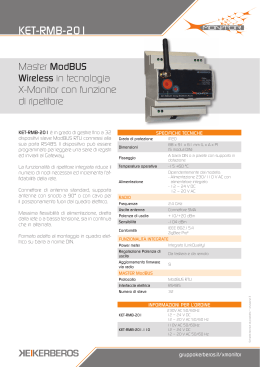
KET-RMB-201 - rete X
Scuola per prevenire, scuola per recuperare
Presentazione corso
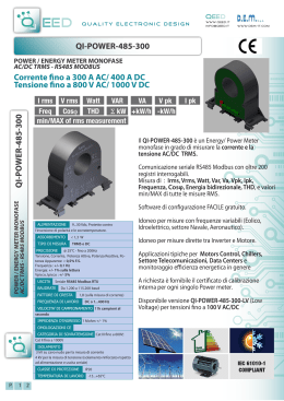
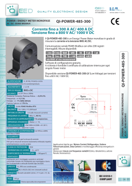
QI-PO WER-485-300 QI-POWER-485-300 Corrente fino a
qi-power-485-300
Fisiocard S.r.l. - Centro Medico Polispecialistico Convenzionato Roma
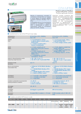
GTW-MPB9 - EDELWEISS actuators
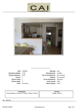
Città CANNES Superficie abitabile 72 M² Terrazza Superficie 40 M²
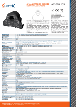
Analizzatore rete elettrica