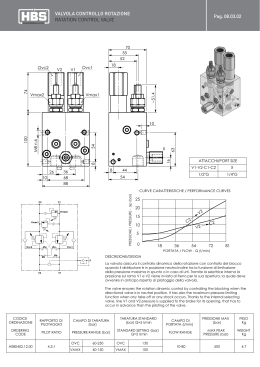
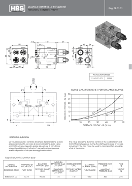
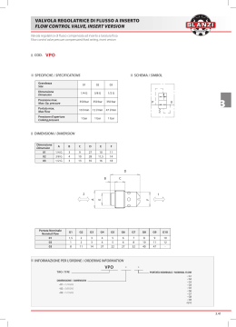
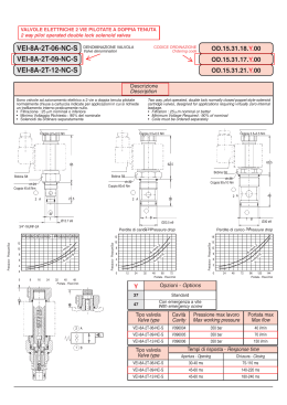
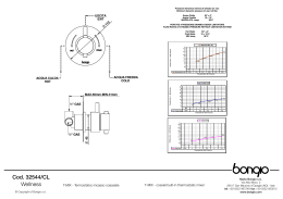
IMPIANTISTICA GAS • gas plants
IMPIANTISTICA GAS • gas plants
Insert Deal srl via dei Boschi, 40 • 20058 Villasanta (MI)
Insert Deal srl via dei Boschi, 40 • 20058 Villasanta (MI)
Tel: +39 039 302 035 r.a. • Fax: +39 039 303 258
Tel: +39 039 302 035 r.a. • Fax: +39 039 303 258
e-mail: [email protected] • www.idinsertdeal.com
e-mail: [email protected] • www.idinsertdeal.com
QUADRO DI DECOMPRESSIONE MODULARE A DOPPIO INGRESSO - QM
brevettato n°- patentino n°
QUADRO DI DECOMPRESSIONE MODULARE SCAMBIO AUTOMATICO
RIPRISTINO A LEVA QSLM
MODULAR DUAL INLET DECOMPRESSION PANEL - QM
patent n°- user licence n°
LEVER RESET AUTOMATIC SWITCHING MODULAR DECOMPRESSION
PANEL QSLM
DESCRIZIONE E CAMPO APPLICATIVO
DESCRIZIONE E CAMPO APPLICATIVO
• Quadri di decompressione a singolo stadio per impianti centralizzati gas tecnici
e laseranti
• Realizzati con riduttori R1100 o R1200 in ottone cromato
• Completi di:
Valvole di intercettazione in ingresso, con dispositivo incorporato di non ritorno del
flusso - valvola di sovrappressione
• Tutti i quadri possono essere equipaggiati con preriscaldatori/pressostati
collegabili ad un sistema di allarme/dispositivi di spurgo/e convogliamento
per gas tossici
• Supporto a muro in acciaio inox 304
• Esecuzioni speciali su richiesta
• Quadri di decompressione a singolo stadio per impianti centralizzati gas tecnici
e laseranti
• Realizzato con riduttore di I° stadio R1200 in ottone cromato
• Ai vantaggi della struttura modulare serie QM si aggiunge la possibilità di gestire in
maniera automatica le 2 linee di alimentazione: all’esaurirsi di un pacco bombole,
il sistema provvede automaticamente ad inserire il pacco di riserva, il cui riduttore è
tarato ad una pressione di uscita leggermente più bassa rispetto a quella del riduttore
della linea in esercizio
• Il principio di funzionamento si basa sulla differenza delle pressioni in uscita
dei 2 riduttori; la leva presente sul frontale stabilisce a quale delle 2 linee viene
assegnata la priorità - e quindi la pressione in uscita maggiore - e si aziona solo
dopo che è avvenuto lo scambio, al momento di sostituire il pacco bombole esaurito.
• Tutti i quadri possono essere equipaggiati: preriscaldatori/pressostati collegabili
ad un sistema di allarme/dispositivi di spurgo/e convogliamento per gas tossici
• Supporto a muro in acciaio inox 304
• Esecuzioni speciali su richiesta
DESCRIPTION AND APPLICATION SCOPE
• Single stage decompression panels for technical and laser gas
centralised systems
• Fitted with chrome plated brass R1100 or R1200 reducers
• Complete with:
Inlet on/off valves, with built in flow non-return device-overpressure valve
• All panels can be equipped with pre-heaters/pressure switches which may be
connected to an alarm system/bleeder devices/and toxic gas conveyors
• 304 stainless steel wall mounting
• Special designs on request.
Dimensioni e componenti
quadro standard
A.P.
B.P.
Standard Panel Dimensions
and Components
• 1
Raccordo di ingresso del quadro
• 1
• 2
Valvola di intercettazione
• 2
• 3
Manometro di alta pressione
• 4
• 5
Riduttore modulare
Vite di regolazione
• 6
Raccordo di uscita
• 7
Bilanciamento riduttore (solo R1200)
• 8
Manometro di bassa pressione
• 9
Valvola di intercettazione
• 10 Telaio
• 11 Valvola di sovrappressione
DESCRIPTION AND APPLICATION SCOPE
• Single stage decompression panels for technical and laser gas
centralised systems
• Fitted with a chrome plated brass R1200 first stage adapter
• As well as its QM series modular design, the panel allows the 2 supply
lines to be automatically controlled: when a cylinder pack is empty, the system will
automatically introduce the backup pack, featuring an reducer calibrated to an outlet
pressure slightly lower than the operating line reducer pressure.
• The operating principle is based on the outlet pressure differential between
the 2 reducers; the lever located on the front of the panel determines which of the 2
lines will have priority - and therefore the higher outlet pressure - and will operate only
after the line switching has taken place, i.e. when the cylinder pack is empty.
• All panels can be fitted with: pre-heaters/pressure switches which may
be connected to an alarm system/bleeder devices/and toxic gas conveyors
• 304 stainless steel wall mounting
• Special designs available on request
Panel inlet fitting
On/off valve
• 3 High pressure gauge
• 4 Modular reducer
• 5 Adjusting screw
• 6 Outlet fitting
• 7 Reducer balancer (only with R1200)
• 8 Low pressure gauge
• 9 On/Off valve
• 10 Frame
• 11 Overpressure valve
Dimensioni e componenti
quadro standard con scambio a leva
• 1 Raccordo di ingresso del quadro
• 1
• 2 Valvola di intercettazione
• 2
• 3 Manometri di alta pressione
• 4 Complessivo riduttore modulare
• 5 Leva di scambio
• 6 Raccordo di uscita
6
Lever operated switching standard
panel dimensions and components
• 7 Bilanciamento riduttore
• 8 Manometro di uscita
• 9 Telaio
• 10 Valvole intercettazione ingresso
• 11 Valvole di sovrappressione
Panel inlet fitting
On/off valve
• 3 High pressure gauges
• 4 Modular reducer assembly
• 5 Switching lever
• 6 Outlet fitting
• 7 Reducer balancer
• 8 Outlet pressure gauge
• 9 Frame
• 10 Oulet on/off valves
• 11 Overpressure valve
Insert Deal srl via dei Boschi, 40 • 20058 Villasanta (MI)
Tel: +39 039 302 035 r.a. • Fax: +39 039 303 258
Insert Deal srl via dei Boschi, 40 • 20058 Villasanta (MI)
Tel: +39 039 302 035 r.a. • Fax: +39 039 303 258
e-mail: [email protected] • www.idinsertdeal.com
e-mail: [email protected] • www.idinsertdeal.com
1
DATI TECNICI: QUADRO QM CON RIDUTTORE R1100 - TECHNICAL DATA: QM PANEL WITH R1100 REDUCER
Massima pressione di alimentazione
Maximum supply pressure
Tipo - Type
P IN bar(psi)
LA
15 (218)*
MA – MB - MC
80 (1160)**
HA - HB – HC
HD - HF
220 (3190)
DIAGRAMMA DI PORTATA - FLOW RATE DIAGRAM
220 bar (3190 psi)
Portata - Flow rate Nm3/h
40
P OUT bar (psi)
0.15-1.5 (2-22)
MA
MB
0.8-8 (12-116)
1.5-15 (22-218)
HA
HB
HC
0.8-8
1.5-15
3-30
(12-116)
(2-22)
(44-435)
MC
3-30 (44-435)
HD
HF
5-50
20-200
(73-725)
(290-3190)
250
HB
250
HC
400
HD-HF
600
DATI TECNICI: QUADRO QM CON RIDUTTORE R1200 - TECHNICAL DATA: QM PANEL WITH R1200 REDUCER
Massima pressione di alimentazione
Maximum supply pressure
Tipo - Type
P IN bar (psi)
LA
15 (218)*
MB
80 (1160)**
HB – HC -HD - HF
220 (3190)
220 bar (3190 psi)
HB
1.5-15
(2-22)
P OUT bar (psi)
0.15-1.5 (2-22)
1.5-15 (22-218)
HC
HD
3-30
5-50
(44-435)
(73-725)
Portata - Flow rate Nm3/h
40
250
HF
20-200
(290-3190)
HB
250
HC
400
HD-HF
600
Limite temperatura ambiente - Ambient temperature range
-20 / +60 °C
Guarnizioni (secondo il gas operante) - Seals (according to operating gas)
EPDM - FKM
Controllo - Control
LA-MA-MB-HAHB (membrana - diaphragm)
MC-HC-HD-HF (pistone - piston)
Otturatore bilanciato (solo R1200)
rende la pressione in uscita insensibile alle variazione della pressione di entrata (tranne per la versione LA)
Balanced stopper (only with R1200)
ensures constant outlet pressure when inlet pressure changes (except for LA version)
gas inerti/comburenti
Ø 21,7 mm - 14 fil./1” destro maschio
Connessione IN
gas inerti/comburenti
Ø 20 mm - 14 fil./1” destro maschio
Inert /combustible gases
Ø 21,7 mm - 14t thread./1” right male
IN connection
fuel gas
Ø 20 mm - 14 thread/1” left male
Connessione OUT - OUT connection
3/8” GF
Annotazioni
Pressostati elettrici per comando unità di allarme POUT max. 30bar (solo per gas inerti/comburenti)
Preriscaldatori (solo per gas inerti) * per Acetilene ** per gas disciolti
Notes
Electric pressure switches for alarm unit control; max. calibration 30bar (only for inert/combustible gases)
Pre-heaters (only for inert gases) * for Acetylene - ** for dissolved gases
Peso kg - Weight in kg
portata/flow rate (Nm3/h)
portata/flow rate (Nm3/h)
DATI TECNICI: QUADRO QM CON RIDUTTORE R1200 - TECHNICAL DATA: QSLM PANL WITH R1200 REDUCER
Massima pressione di alimentazione
Maximum supply pressure
Tipo - Type
P IN bar (psi)
LA
15 (218)*
MB - MC
80 (1160)**
220 bar (3190 psi)
P OUT di scambio - Switching bar (psi)
ΔP di scambio - Switching bar
Portata - Flow rate Nm3/h
prin-main 1,5 (22) ripris-reset 1 (15)
0,5 (7)
40
MB
MC
prin-main 10 (145)
prin-main 25 (362)
MB
MC
MB-MC
ripris-reset 8 (116)
ripris-reset 20 (290)
2 (29)
5 (72)
250
HB
HC
HD
HB
HC
HD
HB – HC -HD
220 (3190)
prin-main 10(145) prin-main 25(362) prin-main 45(625)
2
5
10
HB-HC
HD
ripris-reset 8(116) ripris-reset 20(290) ripris-reset 35(507)
(29)
(72)
(145)
250
600
Limite temperatura ambiente - Ambient temperature range
-20 / +60 °C
Guarnizioni (secondo il gas operante) - Seals (according to operating gas)
EPDM - FKM
Controllo - Control
LA-MA-MB-HAHB (membrana - diaphragm)
MC-HC-HD-HF (pistone - piston)
Otturatore bilanciato
Rende la pressione in uscita insensibile alle variazione della pressione di entrata (tranne per la versione LA)
Balanced stopper
Makes outlet pressure insensitive to pack charge status (except for LA version)
gas inerti/comburenti
Ø 21,7 mm - 14 fil./1” destro maschio
Connessione IN
gas inerti/comburenti
Ø 20 mm - 14 fil./1” destro maschio
inert / fuel gases
Ø 21,7 mm - 14 thread/1” right male
IN connection
fuel gas
Ø 20 mm - 14 thread/1” right male
Connessione OUT - Connessione OUT
3/8” GF
Annotazioni
Pressostati elettrici per comando unità di allarme POUT max. 30bar (solo per gas inerti/comburenti)
Preriscaldatori (solo per gas inerti) * per Acetilene ** per gas disciolti
Notes
Electric pressure switches for alarm unit control; max. calibration 30 bar (only for inert/combustible gases)
Pre-heaters (only for inert gases)* for Acetylene - ** for dissolved gases
Peso kg - Weight kg
2
DIAGRAMMA DI PORTATA - FLOW RATE DIAGRAM
portata/flow rate (Nm3/h)
portata/flow rate (Nm3/h)
Insert Deal srl via dei Boschi, 40 • 20058 Villasanta (MI)
Tel: +39 039 302 035 r.a. • Fax: +39 039 303 258
Insert Deal srl via dei Boschi, 40 • 20058 Villasanta (MI)
Tel: +39 039 302 035 r.a. • Fax: +39 039 303 258
e-mail: [email protected] • www.idinsertdeal.com
e-mail: [email protected] • www.idinsertdeal.com
3
QUADRO A SCAMBIO PER AMMONIACA MONTAGGIO A VISTA
SU PANNELLO QSL
SWITCHNG PANEL FOR AMMONIA MOUNTED
OVER A QSL PANEL
DATI TECNICI - TECHNICAL DATA
DESCRIZIONE E CAMPO APPLICATIVO
• Quadri di decompressione a singolo stadio per impianti di ammoniaca
• Realizzato con riduttore di II° stadio R121 interamente in acciaio inox 316L
o in allumino con interni in acc. inox 316L
• La centrale è dotata di valvole di intercettazione in ingresso, convogliamento
per gas tossici
• I quadri possono essere equipaggiati con pressostati collegabili ad un sistema
di allarme
• Supporto pannellabile a muro in acciaio inox lucido
DESCRIPTION AND APPLICATION SCOPE
• Single stage decompression panels for ammonia systems
• Fitted with an all 316L stainless steel (medium pressure) pressure reducer
or an aluminium pressure reducer with 316L stainless steel internal parts for the
R4121 version
• The unit is fitted with inlet on/off valves and toxic gas conveyor
• The panel can be fitted with pressure switches which may be connected
to an alarm system
• 304 stainless steel wall mounting
• Special designs available on request
3121 costruzione integralmente in acciaio inox 316L - R3121 entirely made of 316L stainless steel
R4121 costruzione in alluminio con interni in acciaio inox 316L - R4121 made of aluminium internal parts made of 316L stainless steel
Massima pressione di alimentazionee
Maximum supply pressure
15 bar (218 psi)
Tipo - Type
P IN bar(psi)
P OUT di scambio bar (psi)
dP scambio bar (psi)
Portata Nm3/h
Switching P OUT bar (psi)
P bar (psi)
Flow rate Nm3/h
A
principale-main
ripristino-reset
20
0.5 (7)
1.5 (22)
15 (218)
1 (15)
1 (15)
principale-main
ripristino-reset
B
30
3 (43.5)
2 (29)
Limite temperatura ambiente - Ambient temperature range
-20 / +60 °C
Guarnizioni (secondo il gas operante) - Seals (according to operating gas)
EPDM
Controllo - Control
membrana - diaphragm
Otturatore bilanciato
rende la pressione in uscita insensibile allo stato di carica del pacco
Balanced stopper
makes outlet pressure insensitive to pack charge status
Connessione IN - IN connection
Ø 30 mm - 14 fil./1” sinistro maschio - Ø 30 mm - 14thread/1” left male
Connessione OUT - OUT connection
1/2” GF
Annotazioni - Notes
Peso kg - Weight kg
DIAGRAMMA DI PORTATA - FLOW RATE DIAGRAM
Dimensioni e componenti
Dimensions and Components
• 1 Raccordo di ingresso del quadro
• 1 Panel inlet fitting
• 2 Valvola di intercettazione
• 2 On/off valve
• 3 Manometro
• 3 Inlet pressure gauge
• 4 Complessivo riduttore
• 4 Reducer assembly
• 5 Leva di scambio
• 5 Switching lever
• 6 Raccordo di uscita
• 6 Outlet fitting
• 7 Manometro
• 7 Outlet pressure gauge
• 8 Valvola di intercettazione
• 8 On/off valve
• 9 Telaio
• 9 Frame
portata/flow rate (Nm3/h)
RICAMBI - SPARES
R1100
LA
MA
MB
HA
HB
DIAGRAMMA DI PORTATA - FLOW RATE DIAGRAM
HC
HD
HF
R1200
Kit
cod
Kit
cod
membrana + otturatore + filtro + o-r epdm
diaphragm + stopper + filter + epdm o-r
membrana + otturatore + filtro + o-r viton
diaphragm + stopper + filter +viton o-r
membrana + otturatore + filtro + o-r epdm
diaphram + stopper + filter + epdm o-r
membrana + otturatore + filtro + o-r viton sgrassato uso O2
diaphragm + stopper + filter + grease free r viton o-r O2
otturatore + filtro + o-r epdm
stopper + filter + epdm o-r
otturatore + filtro + o-r vitons grassato uso O2
stopper + filter + grease free viton o-r for O2
otturatore + filtro + o-r epdm
stopper + filter + epdm o-r
otturatore + filtro + o-r viton sgrassato uso O2
stopper + filter + grease free viton o-r for O2
otturatore + filtro + o-r epdm
stopper + filter + epdm o-r
otturatore + filtro + o-r viton
stopper + filter + viton o-r
K5B10209
membrana + otturatore + filtro + o-r epdm
diaphram + stopper + filter + epdm o-r
membrana + otturatore + filtro + o-r epdm
diaphragm + stopper + filter + epdm o-r
membrana + otturatore + filtro + o-r viton sgrassato uso O2
diaphragm + stopper + filter + grease free viton o-r for O2
otturatore + astina + filtro + o-r epdm
stopper + rod + filter + epdm o-r
otturatore + astina + filtro + o-r viton
stopper + rod + filter +g viton o-r
otturatore + astina + filtro + o-r epdm
stopper + rod + filter + epdm o-r
otturatore + astina + filtro + o-r viton sgrassato uso O2
stopper + rod + filter + grease free viton o-r for o O2
otturatore + astina + filtro + o-r epdm
stopper + rod + filter + epdm o-r
k5b10303
K5B10207
K5B10208
MB
HB
K5B10210
K5B10205
HC
K5B10206
K5B10204
K5B10203
HD
HF
k5b10301
k5b10302
k5b10306
k5b10307
k5b10308
k5b10309
k5b10310
K5B10201
K5B10202
R3121
4
LA
Kit
cod
membrana + otturatore + filtro + o-r epdm
diaphragm + stopper + filter + epdm o-r
K5330107
R4121
Kit
cod
membrana + otturatore + filtro + o-r epdm
diaphragm + stopper + filter + epdm o-r
K5330107
salvo diversamente indicato consultare il ns. servizio commerciale
if the required solution is not listed above, please contact our sales office
Insert Deal srl via dei Boschi, 40 • 20058 Villasanta (MI)
Tel: +39 039 302 035 r.a. • Fax: +39 039 303 258
Insert Deal srl via dei Boschi, 40 • 20058 Villasanta (MI)
Tel: +39 039 302 035 r.a. • Fax: +39 039 303 258
e-mail: [email protected] • www.idinsertdeal.com
e-mail: [email protected] • www.idinsertdeal.com
5
QUADRO A DOPPIO STADIO EN20/EN50
TWO STAGE DECOMPRESSION UNIT EN20/EN50
APPLICAZIONE
I quadri di decompressione della serie EN20 e EN 50 trovano la loro principale
applicazione nell’industria e nei settori alimentare, enologico e chimico.
L’utilizzo principale è la separazione del prodotto in stoccaggio dall’aria atmosferica.
Questo evita il deterioramento del prodotto per ossidazione e per prodotti inquinanti la
dispersione in atmosfera sia per evaporazione sia in fase di carica del prodotto.
APPLICATION
Two stage decompression units EN20 and EN50 series have their application in food,
oenological and chemical field and industry. The main use is for the separation of the
stored product from the atmospheric air. That avoid the oxidation of the product and, in
case of polluting materials, the atmospherical dispersion due to evaporation or during
the charging operations.
PRINCIPIO DI FUNZIONAMENTO
Il quadro di decompressione è a doppio stadio. Con il regolatore di I° stadio riduce la
pressione da 220 Bar a 2.5 Bar mentre con il regolatore di II° stadio da 2.5 bar a 5-700
mbar (Vedi versioni Tab sotto). Il quadro è dotato di due ingressi (3A–1A e 3B-1B) per
permettere con una apertura alternata di avere una linea in esercizio ed una in riserva.
Il quadro è alimentato direttamente da bombole. In funzione dei consumi le bombole
possono essere raggruppate su collettori (ns. catalogo rif. Rampe). Il regolatore di I° stadio
è pretarato a 2.5 Bar tramite la vite (6). Il regolatore di II° stadio (2) riduce la pressione ai
valori richiesti dall’applicazione. La pressione è regolabile mediante la vite di regolazione
ed il manometro 8 indica la pressione in uscita. La taratura del regolatore 2 deve essere
fatta in condizione statica. E’ necessario a tal fine applicare una valvola on/off in uscita,
esclusa dalla fornitura. Il riduttore è normalmente aperto pertanto all’apertura di uno dei 2
ingressi (3A–1A e 3B-1B) con valvola on/off chiusa si leggerà una pressione (man.8)
alterata dovuta alla chiusura dell’otturatore. Scaricare il gas presente nel quadro tramite la
valvola on/off. Richiudere la valvola on/off e procedere alla regolazione finale.
PRINCIPLE OF OPERATION
The unit has two stages of decompression. The I° stage regulator reduce the pressure
from 220 Bar to 2,5 Bar, while the II° stage reduce from 2,5 bar to 5-700 mbar (see table
below). The unit has two inlets (3A-1A and 3B-1B). An alternate opening allows to have an
operating line and a reserve one. The unit is feeded directly by the cylinders. According to
the consumption, the cylinders can be assembled in manifold (see our catalogue ref.
Manifold). The I° stage unit is pre-calibrate to 2,5 Bar by the screw (6). The II° stage unit
(2) reduce the pressure to the requested value. The pressure is adjustable by the
regulation screw and the gauge 8 show the outlet pressure. The regulator 2 has to be
calibrated in a static phase. For this purpose is necessary apply an outlet on-off valve (not
supplied). Normally the reducer is open; opening one of the two inlets (3A-1A snd 3B-1B)
with the on-off valve closed you’ll read an alterate pressure due to the closing of the
regulator valve. Discharge the gas of the unit by the on-off valve. Close the on-off valve
and continue the final regulation.
CARATTERISTICHE TECNICHE - TECHNICAL DETAILS
Quadro di decompressione con apparecchi montati a vista su pannello in acciaio inox 304
Decompression unit with devices mounted on panel of stainless steel 304
Pressione di ingresso massima
Pressione di uscita
Attacco entrata
Max. designe pressure
Outlet pressure range
Inlet connection
Attacco uscita
Outlet connection
Capacità serbatoio
Capacity tank
220 bar gas N2
80 bar gas CO2
5 – 700 m bar secondo il modello - according to the model
n° 2
ø21.7 mm – 14 filetti/1” maschio dex.con valvole di intercettazione
ø21.7 mm – 14 thread/1” male with interception valve
n°1
EN 20
3/4” gas femm.
2” gas F
3/4” BSP female
EN 50
1” gas femm.
1” BSP female
RIDUTTORE DI I° STADIO - I° STAGE PRESSURE REGULATOR MOD. RM 1200
Materiale di costruzione
Material of construction
corpo
body
campana
bonnet
parti interne
internal parts
membrana
diaphragm
Otturatore
plug
bilanciato
balanced
Tenuta otturatore
plug seal
resiliente
soft
Pressione uscita I° stadio
Valvola di sicurezza
Manometro entrata
Manometro uscita
outlet press. I° stage
safety valve
inlet gauge
outlet gauge
ottone (CW614N)
ottone (CW614N)
ottone (CW614N)
NBR + PTFE
brass (CW614N)
brass (CW614N)
brass (CW614N)
NBR + PTFE
2.5 bar
6 bar
0-315 bar (gas N2) / 0-160 bar (gas CO2)
0-16 bar
RIDUTTORE DI II° STADIO - II° STAGE PRESSURE REGULATOR MOD. R160
Materiale di costruzione Material of construction
corpo
body
campana
bonnet
parti interne
intern. parts
membrana
diaphragm
Pressione uscita I° stadio
outlet press. I° stage
regolabile
adjustable
Manometro uscita
outlet gauge
0-60 mbar, 0-100 mbar, 0-1.6 Bar
alluminio
alluminio
ottone (CW614N)
NBR
aluminium
aluminium
brass (CW614N)
NBR
RICAMBI - SPARE PARTS
Kit completo parti interne
Kit completo valvole ingresso
Manometri
Complete kit for internal parts
Complete kit for inlet valves
Gauges
ACCESSORI - OPTIONALS
MODELLO
model
pressione uscita
outlet pressure
portata
flow
GAS
codice
code
EN 20 / A
5 - 45 mbar
20 Nm3/h
EN 20 / B
20 - 200 mbar
20 Nm3/h
EN 20 / C
150 - 700 mbar
20 Nm3/h
EN 50 / A
5 - 45 mbar
50 Nm3/h
N2
CO2
N2
CO2
N2
CO2
N2
CO2
QFC1JN07
QFC1LN03
QFC1JP07
QFC1LP03
QFC1JQ07
QFC1LQ03
QDC1JN07
QDC1LN03
Valvola on/off in uscita
Rampe
Serpentine di collegamento
Valvola a doppio effetto
On/off valve
Manifold
Pig-tail connectors
Two-way exhausting valve
salvo diversamente indicato consultare il ns. servizio commerciale
if the required solution is not listed above, please contact our sales office
Unità con copertura a richiesta
Units with cover upon request
6
Insert Deal srl via dei Boschi, 40 • 20058 Villasanta (MI)
Tel: +39 039 302 035 r.a. • Fax: +39 039 303 258
Insert Deal srl via dei Boschi, 40 • 20058 Villasanta (MI)
Tel: +39 039 302 035 r.a. • Fax: +39 039 303 258
e-mail: [email protected] • www.idinsertdeal.com
e-mail: [email protected] • www.idinsertdeal.com
7
QUADRO A DOPPIO STADIO R2034/160
TWO STAGE DECOMPRESSION UNIT R2034/160
APPLICAZIONE
I regolatori della serie R2034/160 trovano la loro principale applicazione nell’industria e
nei settori alimentare, enologico e chimico. L’utilizzo principale è la separazione del
prodotto in stoccaggio dall’aria atmosferica. Questo evita il deterioramento del prodotto
per ossidazione e per prodotti inquinanti la dispersione in atmosfera sia per
evaporazione sia in fase di carica del prodotto
APPLICATION
Two stage decompression units R2034/160 series have their application in food,
oenological and chemical field and industry. The main use is for the separation of the
stored product from the atmospheric air. That avoid the oxidation of the product and, in
case of polluting materials, the atmospherical dispersion due to evaporation or during
the charging operations.
PRINCIPIO DI FUNZIONAMENTO
Il regolatore è a doppio stadio. il regolatore di I° stadio (Pos. 3) riduce la pressione da 220
Bar a 2.5 Bar mentre il regolatore di II° stadio (Pos. 4) da 2.5 a 5-700 mbar (Vedi versioni
di seguito elencate). Il regolatore è composto da un ingresso che può essere predisposto
per il montaggio del regolatore direttamente sulla bombola, o sui collettori di distribuzione
(ns. catalogo rif. Rampe). La pressione è regolabile mediante la vite di regolazione
(Pos. 1) ed il manometro (Pos. 2) indica la pressione in uscita. La taratura del regolatore di
II° stadio deve essere fatta in condizione statica. E’ necessario a tal fine applicare una
valvola on/off in uscita, esclusa dalla fornitura. Il riduttore è normalmente aperto pertanto
all’apertura dell’ alimentazione con valvola on/off chiusa si leggerà una pressione (Pos. 2)
alterata dovuta alla chiusura dell’otturatore. Scaricare il gas presente nel quadro tramite la
valvola on/off. Richiudere la valvola on/off e procedere alla regolazione finale.
PRINCIPLE OF OPERATION
The unit has two stages of decompression. The I° stage regulator (Item. 3) reduce the
pressure from 220 Bar to 2,5 Bar, while the II° stage (Item. 4) reduce from 2,5 to 5-700
mbar (see table below). The unit has one inlet. The unit is feeded directly by the cylinders.
According to the consumption, the cylinders can be assembled in manifold (see our
catalogue ref. Manifold). The pressure is adjustable by the regulation screw (Item. 1) and
the gauge (Item. 2) show the outlet pressure. The II°stage regulator has to be calibrated
in a static phase. For this purpose is necessary apply an outlet on-off valve (not supplied).
Normally the reducer is open; opening the inlet pressure with the on-off valve closed
you’ll read an alterate pressure due to the closing of the regulator valve. Discharge the
gas of the unit by the on-off valve. Close the on-off valve and continue the final regulation.
CARATTERISTICHE TECNICHE - TECHNICAL DETAILS
Quadro di decompressione con apparecchi montati a vista su pannello in acciaio inox 304
Decompression unit with devices mounted on panel of stainless steel 304
Pressione di ingresso massima
Pressione di uscita
Attacco entrata
Max. designe pressure
Outlet pressure range
Inlet connection
Attacco uscita
Outlet connection
220 bar gas N2
80 bar gas CO2
5mbar-1,2 bar secondo il modello
according to the model
n° 1
Attacco per bombola e per rampa
Connection for bottlr and for manifold
3/4” gas femm.
R2034/160
3/4” BSP female
RIDUTTORE DI I° STADIO - I° STAGE PRESSURE REGULATOR MOD. R 2034
Materiale di costruzione
Material of construction
corpo
body
campana
bonnet
parti interne
internal parts
membrana
diaphragm
Otturatore
plug
bilanciato
balanced
Tenuta otturatore
plug seal
resiliente
soft
Pressione uscita I° stadio
Valvola di sicurezza
Manometro entrata
Manometro uscita
outlet press. I° stage
safety valve
inlet gauge
outlet gauge
ottone (CW614N)
ottone (CW614N)
ottone (CW614N)
NBR + PTFE
brass (CW614N)
brass (CW614N)
brass (CW614N)
2.5 bar
6
bar
0-315 bar (gas N2) / 0-160 bar (gas CO2)
0-16 bar
RIDUTTORE DI II° STADIO - II° STAGE PRESSURE REGULATOR MOD. R160
Materiale di costruzione Material of construction
corpo
body
alluminio
campana
bonnet
alluminio
parti interne
intern. parts
ottone (CW614N)
membrana
diaphragm
NBR
Pressione uscita I° stadio
outlet press. I° stage
regolabile
adjustable
Manometro uscita
outlet gauge
0–60 mbar, 0–100 mbar, 0–1.6 bar
aluminium
aluminium
brass (CW614N)
RICAMBI - SPARE PARTS
Kit completo parti interne
Manometri
Complete kit for internal parts
Gauges
ACCESSORI - OPTIONALS
8
MODELLO
model
pressione uscita
outlet pressure
portata
flow
R2034/160 A2
5 - 45 mbar
10 Nm3/h
R2034/160 B2
20 - 200 mbar
10 Nm /h
R2034/160 C2
150 - 700 mbar
10 Nm3/h
3
GAS
codice
code
N2
QQG1JN07
QQG1LN03
QQG1JP07
QQG1LP03
QQG1JQ07
QQG1LQ03
CO2
N2
CO2
N2
CO2
Valvola on/off in uscita
Rampe
Serpentine di collegamento
Valvola a doppio effetto
On/off valve
Manifold
Pig-tail connectors
Two-way exhausting valve
salvo diversamente indicato consultare il ns. servizio commerciale
if the required solution is not listed above, please contact our sales office
Insert Deal srl via dei Boschi, 40 • 20058 Villasanta (MI)
Tel: +39 039 302 035 r.a. • Fax: +39 039 303 258
Insert Deal srl via dei Boschi, 40 • 20058 Villasanta (MI)
Tel: +39 039 302 035 r.a. • Fax: +39 039 303 258
e-mail: [email protected] • www.idinsertdeal.com
e-mail: [email protected] • www.idinsertdeal.com
9
RAMPE MODULARI AD USO INDUSTRIALE E LABORATORIO
INDUSTRIAL AND LABORATORY USE MODULAR MANIFOLDS
CHIAVE DI CODIFICA - CODING KEY
DESCRIZIONE E CAMPO APPLICATIVO
TIPO - TYPE
PARTICOLARITA’ - DETAILS
B
C
D
F
H
P
Q
01 PRESSOSTATI/PRESSURE SWITCHES
02 PRERISCALDATORI/PRE-HEATERS
03 SPURGHI/BLEEDER DEVICES
04 CONVOGLIAMENTO/CONVEYOR
07 SPURGHI+CONVOGL/BLEEDERS+CONV.
09 SPURGHI+PRERISC/BLEEDERS+PREHEAT
10 PRESSOST+PRERISC/PRESS. SWI.+PREHEAT.
11 PRESS+PRERIS+SPU/PRESS. S.+PREH.+BLEED
QM
QSLM
EN50
EN20
QSL
R2034+150
R2034+160
• Le rampe sono adatte per la centralizzazione di impianti gas tecnici e gas puri
ad uso industriale e laboratorio
• Sistema modulare brevettato costruito in ottone cromato, acciaio inox 316L
ed in esecuzione speciale per ammoniaca in allumino +316L
• Valvola di intercettazione per ogni posto bombola
• Dispositivo di non ritorno del flusso incorporato
• Microregolatore di sicurezza per lo spurgo dei circuiti in bassa pressione (~8bar).
Se ne consiglia l’utilizzo, operando con gas tossici, corrosivi e puri.
• Supporto a muro in acciaio inox 304
Le rampe gas puri sono adatte per la centralizzazione di impianti gas puri per laboratori
di analisi, gas cromatografia etc.
DESCRIPTION AND APPLICATION SCOPE
• The manifolds are suitable for centralizing technical and pure gas systems
for industrial and laboratory use
• Patented modular system made of chrome-plated brass, 316L stainless steel
and a special +316L aluminium solution for ammonia based applications
• On-off valve for each cylinder
• Integrated flow non-return device
• Low pressure (~8bar) circuit bleed safety micro-regulator. Recommended
when toxic, corrosive and pure gases are used.
• 304 stainless steel mounting
Q a b c d e xx (..)
The pure gas manifolds are suitable to centralize pure gas systems for analysis
laboratories, chromatography gases etc.
RIDUTTORE
REDUCER
B
C
E
G
R1100
R1200
R121
R2034
MATERIALE
MATERIAL
1 Ottone
Brass
3 Acc. inox 316
316 stain. steel
7 Alluminio +316
Alluminium+316
PRESS. IN
PRESS. IN
B 15 bar
L 80 bar
J 220 bar
PRESS. OUT
PRESS. OUT
A
B
D
E
F
G
V
N
P
Q
AA
0,2-1.5 bar
0.3-3 bar **
0.8-8 bar *
1.5-15 bar
3-30 bar
5-50 bar
20-200 bar
5-45 mbar
20-200 mbar
150-700
0.18-1.2bar
GAS OPERANTE
OPERATION GAS
01
02
03
05
06
07
09
11
13
15
16
17
19
26
Aria Compressa/Compressed air
Ammoniaca/Ammonia
Anidr.carbonica/Carbon dioxide
Argon/Argon
Aria/Air
Azoto/Nitrogen
Elio/Helium
Idrogeno/Hydrogen
Metano/Natural gas
Ossigeno/Oxigen
Propano/Propane
Protossido d’azoto/Nitrogen oxide
Acetilene/Acetylene
mix Argon/CO2/Argon/CO2mix
Dimensioni e componenti
• 1
Valvola di intercettazione
• 2
Raccordo di entrata
• 3
Elemento filtrante
• 4
Raccordo di uscita
• 5
Collettore
• 6
Controdado di blocco
• 7
Tappo
• 8
Telaio
• 9
Tappo 3/8” attacco accessori
• 10 Microregolatore
Dimensions and Components
senza microregolatore
without micro-regulator
rappresentazione rampa 6 posti
6-cylinder manifold
con microregolatore
with micro-regulator
• 1
•
•
•
•
•
•
•
•
•
10
rappresentazione rampa biposto
2-cylinder manifold
On-off valve
2 Inlet fitting
3 Filter element
4 Outlet fitting
5 Manifold
6 Lock nut
7 Plug
8 Frame
9 3/8” accessory connection plug
10 Micro-regulator
Insert Deal srl via dei Boschi, 40 • 20058 Villasanta (MI)
Tel: +39 039 302 035 r.a. • Fax: +39 039 303 258
Insert Deal srl via dei Boschi, 40 • 20058 Villasanta (MI)
Tel: +39 039 302 035 r.a. • Fax: +39 039 303 258
e-mail: [email protected] • www.idinsertdeal.com
e-mail: [email protected] • www.idinsertdeal.com
11
DATI TECNICI - TECHNICAL DATA
Massima pressione di alimentazione - Maximum supply pressure
220 bar (3200 psi)
Limite temperatura ambiente - Ambient temperature range
-20 / +60 °C
Versioni disponibili - Available versions
1 – 2 – 3 – 4 – 5 – 6 posti/cylinders
Guarnizioni (secondo il gas operante) - Seals (according to gas used)
NBR – EPDM - FKM
Connessioni IN/OUT
gas inerti / comburenti
Ø 21,7 mm - 14 fil./1” destro-maschio
IN – OUT connections
inert / combustible gases
Ø 21,7 mm - 14 thread./1” right male
gas combustibili
Ø 20 mm - 14 fil./1” sinistro maschio
fuel gases
Ø 20 mm - 14 thread./1” left male
gas ammoniaca
Ø 30 mm - 14 fil./1” sinistro maschio
ammonia gases
Ø 30 mm - 14 thread./1” left male
Attacco accessori (microregolatore/pressostato) - Connection for accessories (micro-regulator/pressure switch)
3/8” GF
Peso kg - Weight kg
Senza micro - Without micro-regulator
[1p] = 1.3 [2p] = 3.4 [3p] = 4.7
[4p] = 6.5
[5p] = 8.5
[6p] =10.3
Con micro - With-micro regulator
[1p] = 1.5 [2p] = 3.6 [3p] = 5.3
[4p] = 7.3
[5p] = 9.5
[6p] =11.8
DIAGRAMMA DI PORTATA - FLOW RATE DIAGRAM
RICAMBI - SPARES
Kit
tipo/type
cod
Kit
tipo/type
cod
otturatore
stopper
NBR
EPDM
VITON
NBR
EPDM
VITON
NBR
EPDM
VITON
KR110101
KR110102
KR110103
KR110111
KR110112
KR110113
KR110121
KR110122
KR110123
raccordi entrata/uscita sx
ls in/out fittings
NBR
EPDM
VITON
NBR
EPDM
VITON
NBR
EPDM
VITON
KR110131
KR110132
KR110133
KR110141
KR110142
KR110143
KR110171
KR110172
KR110173
collettore
manifold
raccordi entrata/uscita dx
RH in/out fittings
valvola completa
complete valve
tappo m18x1,5
m18x1.5 plug
salvo diversamente indicato consultare il ns. servizio commerciale
Pressione entrata (bar)
inlet pressare (bar)
if the required solution is not listed above, please contact our sales office
CHIAVE DI CODIFICA - CODING KEY
PARTICOLARITA’ - DETAILS
00 Senza micro/Without micro
03 Microregolatore*/Microregulator*
portata/flow rate (Nm3/h)
*uso gas puri-laboratorio/*for pure gases-laboratory use
Sistema brevettato
Questo sistema brevettato consente un facile, rapido e sicuro assemblaggio del collettore, in
funzione del numero di utenze da allacciare al collettore stesso. E’ possibile ordinare il collettore
montato o i singoli componenti per una più agevole gestione del magazzino: questa nuova
soluzione costruttiva, totalmente priva di saldature, permette all’utente di montare o modificare
una rampa già esistente secondo le precise esigenze del momento con uno stock minimo di
componenti. Le operazione di assemblaggio sono rapide e sicure: le tenute sono assicurate da
guarnizioni, tali guarnizioni sono fornite con mescola compatibile con i tipi di gas impiegati.
Il sistema di bloccaggio non determina la tenuta delle parti ma solo il bloccaggio necessario.
Non esistono tenute a pressione tra le parti con l’eliminazione di perdite dovute ad allentamenti
nel tempo. Le versioni per impiego in laboratorio sono dotate di sistema di spurgo con
microriduttore su ogni posto bombola. Questo nuovo sistema con microriduttore permette di
spurgare i circuiti scaricando il gas con pressione ridotta a circa 8 bar, con grandi vantaggi in
termini di sicurezza e praticità delle operazioni di spurgo.
Patented System
This patented system ensures an easy, quick and safe manifold assembly, according to the
number of cylinders to be connected to the manifold. The customer can order a fully assembled
manifold or single components to ensure an easier stock control; this new, totally weld free
design solution allows the user to fit or modify an existing manifold to meet the specific
customer’s needs, keeping stock requirements to a minimum. The assembly operations are
quick and safe: tightness is ensured by seals made of a mix compatible with the types of gases
used. The locking system is not fitted to ensure component tightness, but only to lock the
cylinders in position. There are no pressurised seals between the components, thus avoiding
leaks due to slackening caused by wear and tear. The versions for laboratories are supplied with
a micro-reducer based bleeder systems on each cylinder slot. This new micro-reducer based
system allows the circuits to be bled by discharging the gas at a reduced pressure of 8 bar,
which ensures greater safety and ease of bleeding operations.
12
R a b c xx (..)
TIPO - TYPE
MATERIALE
MATERIAL
POSTI BOMBOLA
N°OF CYL. HELD
1 Laboratorio o industriale
Lab. or industrial
4 Forte erogazione
Fast gas supply
5 Carica bombole
Cylinder charge
1 Ottone
Brass
3 Acc. inox 316
Aluminium
7 Alluminio +316
316 Stainless steel
1:1
2:2
3:3
4:4
5:5
6:6
posto/cylinder
posti/cylinders
posti/cylinders
posti/cylinders
posti/cylinders
posti/cylinders
GAS OPERANTE
OPERATION GAS
01
02
03
05
06
07
09
11
13
15
16
17
19
26
Aria Compressa/Compressed air
Ammoniaca/Ammonia
Anidr.carbonica/Carbon dioxide
Argon/Argon
Aria/Air
Azoto/Nitrogen
Elio/Helium
Idrogeno/Hydrogen
Metano/Natural gas
Ossigeno/Oxigen
Propano/Propane
Protossido d’azoto/Nitrogen oxide
Acetilene/Acetylene
mix Argon/CO2/Argon/CO2mix
Insert Deal srl via dei Boschi, 40 • 20058 Villasanta (MI)
Tel: +39 039 302 035 r.a. • Fax: +39 039 303 258
Insert Deal srl via dei Boschi, 40 • 20058 Villasanta (MI)
Tel: +39 039 302 035 r.a. • Fax: +39 039 303 258
e-mail: [email protected] • www.idinsertdeal.com
e-mail: [email protected] • www.idinsertdeal.com
13
POSTI UTILIZZO PER GAS INDUSTRIALE E LABORATORIO
CONTROL UNIT FOR INDUSTRIAL AND LABORATORY GASES
DESCRIZIONE E CAMPO APPLICATIVO
• Posto di utilizzo in cassetta per impianti di distribuzione e apparecchiature
saldature gas tecnici
• Realizzato con Riduttore di II° Stadio in ottone tipo R114 ed R121
• Supporto a muro in acciaio inox 304
CARATTERISTICHE TECNICHE - TECHNICAL DATA
Massima pressione di alimentazione - Maximum supply pressure
Mod.
R114
Tipo-Type
A1-B1-C1-E1
P IN bar(psi)
30 (435)
(3-22)
Si consiglia l’uso della valvola di sicurezza per posti utilizzo Ossigeno e gas combustibili
DESCRIPTION AND APPLICATION SCOPE
• Control unit for distribution systems and technical gas welding equipment
• Fitted with a R114 and R121 type brass second stage reducer
• 304 stainless steel wall mounting
R121
F1-G1-L1
A1-B1
50 (725)
15 (218)
C1
E1
F1-G1-L1
20 (290)
30 (435)
50 (725)
The use of a safety valve when oxygen and fuel gases are used is recommended
50 bar (725 psi)
P OUT di scambio bar - Exchange (psi)
(A1)
(B1)
(C1)
(E1)
0.2-1.5
0.3-3
0.8-8
1.5-15
(4-44)
(12-116)
(F1)
(G1)
1.5-15 (22-218)
3-30 (44-435)
(A1)
0.2-1.5 (3-22)
0.8-8 (12-116)
1.5-15 (22-218)
(F1)
(G1)
1.5-15(22-218)
3-30
(A1)
9
Portata - Flow rate Nm3/h
(B1)
(C1)
12
20
(E1)
40
(22-218)
(L1)
5-50 (73-725)
(B1)
0.3-3 (4-44)
(L1)
5-50 (73-725
Limite temperatura ambiente - Ambient temperature range
Guarnizioni (secondo il gas operante) - Seals (according to operating gas)
Controllo - Control
A1-B1-C1-E1-F1 membrana - diaphragm
Manometro - Pressure gauge
Ø63 secondo normativa - conforming to EN837EN837
Connessione IN - IN connection
valvola a sfera - ball valve 3/8”GF
R114
Connessione OUT
industriale - Industrial
3/8”GM
OUT connection
laboratorio - Laboratory
3/8” GF
Annotazioni
completo di dado 3/8” e portagomma
Note
ø8-ø6 solo nella versione con press. max 15 bar
complete with 3/8” nut and ø8-ø6 seal holder
only in the 15 bar max. pressure version
Peso kg. - Peso kg.
2.4kg
40
(A1)
20
(F1)
110
(B1)
30
40
110
(G1)
150
(L1)
180
-20 / +60 °C
NBR – EPDM - FKM
G1-L1 pistone - piston
valvola a sfera - vball valve 3/8”GF
R121
1/2”GM
1/2”GF
completo di dado 1/2” e portagomma
ø8-ø6 solo nella versione con press. max 15 bar
Complete with 1/2” nut and ø8-ø6 seal holder
only in the 15 bar max. pressure version
3kg
portata/flow rate (Nm3/h)
portata/flow rate (Nm3/h)
tata/
DIAGRAMMA DI PORTATA - FLOW RATE DIAGRAM
portata/flow rate (Nm3/h)
portata/flow rate (Nm3/h)
14
Insert Deal srl via dei Boschi, 40 • 20058 Villasanta (MI)
Tel: +39 039 302 035 r.a. • Fax: +39 039 303 258
Insert Deal srl via dei Boschi, 40 • 20058 Villasanta (MI)
Tel: +39 039 302 035 r.a. • Fax: +39 039 303 258
e-mail: [email protected] • www.idinsertdeal.com
e-mail: [email protected] • www.idinsertdeal.com
15
POSTI UTILIZZO PER MISCELA Argon/CO2
CON FLUSSOMETRO O MANOFLUSSOMETRO
CONTROL UNIT FOR Argon/CO2
MIXTURE WITH FLOWMETER OR PRESSURE GAUGE AND FLOWMETER
DESCRIZIONE E CAMPO APPLICATIVO
• Posto di utilizzo in cassetta apparecchiature per saldature gas tecnici
• Realizzato con Riduttore di II° Stadio in ottone tipo R114 -A1
• Supporto a muro in acciaio inox 304
CARATTERISTICHE TECNICHE - TECHNICAL DATA
Massima pressione di alimentazione - Max. supply pressure
Campo
Range
Mod.
R114
Tipo- Type
A1
P IN bar(psi)
30 (435)
Limite temperatura ambiente - Ambient temperature range
Guarnizioni (secondo il gas operante) - Seals (according to the gas used)
Controllo - Control
Mano-flussometro Argon/CO2 - Pressure gauge-flowmeter Argon/CO2
Flussometro con valvola a spillo - Flow meter needle valve
Connessione IN - IN connection
Connessione OUT industriale - industrial use
OUT connection
laboratorio - laboratory use
Peso kg. - Weight kg.
DESCRIPTION AND APPLICATION SCOPE
• Control unit for technical gas welding equipment
• Supplied with a R114-A1 type brass second stage reducer
• 304 stainless steel wall mounting
30 bar (435 psi)
Portata - Flow rate Nm3/h
9
P OUT bar(psi)
0.2-1.5 (3-22)
-20 / +60 °C
NBR – EPDM - FKM
membrana - diaphragm
0 – 30 lt/min
–
valvola a sfera 3/8”GF - 3/8”GF ball valve
Dado 3/8” portagomma ø8 - 3/8” nut ø8 seal holder
GF
2.9 kg
DIAGRAMMA DI PORTATA - FLOW RATE DIAGRAM
portata/tata/
flow rate (Nm3/h)
CHIAVE DI CODIFICA - CODING KEY
PARTICOLARITA’ - DETAILS
Q a b c d e xx (..)
GAS OPERANTE
OPERATION GAS
TIPO - TYPE
180
L Industriale
Industrial use
M con flussometro
wih flowmeter
N laboratorio
Industrial use
RIDUTTORE
ADAPTER
D R114
E R121
16
01 MANOFLUX
PRESS. GAUGE-FLOWMETER
02 FLUSSOMETRO/FLOWMETER
PRESS. OUT
MATERIALE
MATERIAL
PRESS. IN
1 Ottone
Brass
3 Acc. inox 316
316 stainless steel
B 15 bar
L 80 bar
J 220 bar
A
B
D
E
F
G
0,2-1.5 bar
0.3-3 bar **
0.8-8 bar *
1.5-15 bar
3-30 bar
5-50 bar
01
02
03
05
06
07
09
11
13
15
16
17
19
26
Aria Compressa/Compressed air
Ammoniaca/Ammonia
Anidr.carbonica/Carbon dioxide
Argon/Argon
Aria/Air
Azoto/Nitrogen
Elio/Helium
Idrogeno/Hydrogen
Metano/Natural gas
Ossigeno/Oxigen
Propano/Propane
Protossido d’azoto/Nitrogen oxide
Acetilene/Acetylene
mix Argon/CO2/Argon/CO2mix
Insert Deal srl via dei Boschi, 40 • 20058 Villasanta (MI)
Tel: +39 039 302 035 r.a. • Fax: +39 039 303 258
Insert Deal srl via dei Boschi, 40 • 20058 Villasanta (MI)
Tel: +39 039 302 035 r.a. • Fax: +39 039 303 258
e-mail: [email protected] • www.idinsertdeal.com
e-mail: [email protected] • www.idinsertdeal.com
17
POSTO UTILIZZO PER RIDUTTORE R2010
CONTROL UNIT FOR R2010 REDUCER
DESCRIZIONE E CAMPO APPLICATIVO
• Posto di utilizzo in cassetta apparecchiature per gas puri
• Realizzato per il montaggio a muro dei riduttori della serie R2010
• Supporto pannellabile a muro in acciaio inox lucido
DESCRIPTION AND APPLICATION SCOPE
• Control unit for pure gases equipment
• Designed to wall mount R2010 series reducers
• Bright stainless steel mounting which may be wall hung
CARATTERISTICHE TECNICHE - TECHNICAL DATA
Massima pressione di alimentazione - Maximum supply pressure 20 bar
20 bar
P IN bar
P OUT bar
Tipo
A
20
0,15 -1,5
Type
B
20
0.3 - 3
C
20
0.8 - 8
Valvola di non ritorno del flusso in ottone cromato - Chrome plated brass flow non-return valve
Connessione IN - IN connection
Raccordo tipo GYROLOCK ø6 - GYROLOCK ø6 type fitting
Connessione OUT - OUT connection
1/4” -1/2” GM
Guarnizioni (secpndo il gas operante) - Seals (according to operating gas)
NBR - EPDM - FKM
Peso kg. - Weight kg.
CHIAVE DI CODIFICA - CODING KEY
PARTICOLARITA’ - DETAILS
01 senza copertura raccordo ø6/without cover, ø6 fitting
03 senza copertura raccordo ø10/without cover, ø10 fitting
06 senza copertura raccordo ø8/without cover, ø8 fitting
V A b xx (..)
TIPO - TYPE
A Presa per R2010
Outlet for R2010
18
MATERIALE
MATERIAL
GAS OPERANTE
OPERATION GAS
1 Ottone
Ottone
3 Acc. inox 316
316 stainless steel
01
02
03
05
06
07
09
11
13
15
16
17
19
26
41
Aria Compressa/Compressed air
Ammoniaca/Ammonia
Anidr.carbonica/Carbon dioxide
Argon/Argon
Aria/Air
Azoto/Nitrogen
Elio/Helium
Idrogeno/Hydrogen
Metano/Natural gas
Ossigeno/Oxigen
Propano/Propane
Protossido d’azoto/Nitrogen oxide
Acetilene/Acetylene
mix Argon/CO2/Argon/CO2mix
Monoss.di carbonio/Carbon monoxide
Insert Deal srl via dei Boschi, 40 • 20058 Villasanta (MI)
Tel: +39 039 302 035 r.a. • Fax: +39 039 303 258
Insert Deal srl via dei Boschi, 40 • 20058 Villasanta (MI)
Tel: +39 039 302 035 r.a. • Fax: +39 039 303 258
e-mail: [email protected] • www.idinsertdeal.com
e-mail: [email protected] • www.idinsertdeal.com
19
MISCELATORI
MIXERS
DESCRIZIONE E CAMPO APPLICATIVO
• Si tratta di un'apparecchiatura in grado di formare una o più miscele di percentuale
arbitraria tra due o tre gas, il sistema usato garantisce le piu' alte precisioni ottenibili
con grande flessibilita' di utilizzo.
• Per tutte le applicazioni che richiedono una miscela di gas estremamente precisa e
costante nel tempo, nelle versioni standard possono essere controllate miscele di
tutti i gas tecnici sia binarie che ternarie, nei rapporti e portate desiderati. (altre
combinazioni a richiesta)
CARATTERISTICHE TECNICHE - TECHNICAL DATA
Massima pressione di esercizio - Maximum operating pressure
Pressione di uscita ridotta - Reduced outlet pressure
Limite temperatura ambiente - Ambient temperature range
Guarnizioni (secondo il gas operante) - Seals (according to operating gas)
Connessioni IN - OUT / IN -OUT connections
Scala flussimetri in percentuale - Flowmeter scale given as percentage
Portata - Flow rate
DESCRIPTION AND APPLICATION SCOPE
• This equipment is capable of generating one or more gas mixtures containing two
or three gases at any concentration percentage. The system ensures the highest
possible accuracy as well as a great flexibility of use.
• For all applications requiring extremely accurate and consistent gas mixtures, the
standard versions allow the user to control all technical gas mixtures containing two
or three gases, both in the ratios and flow rates wished (other combinations
available on request).
4 - 8 bar (58-116 psi)
1.5 bar (22psi)
-20 / +60 °C
NBR – EPDM - FKM
Raccordo tipo GYROLOCK ø10 - GYROLOCK ø10 type fitting
MB3000
MB6000
100% 1.5mc/h
100% 3mc/h
3000Nl/h (3Nm3/h)
6000Nl/h (6Nm3/h)
APPLICAZIONI TIPICHE - TYPICAL APPLICATIONS
SETTORE ALIMENTARE (CONFEZIONAMENTO ATM):
Miscele di N2 / CO2 - N2 / CO2 / O2
FOOD INDUSTRY ( ATM PACKAGING ):
Mixtures of N2 / CO2 - N2 / CO2 / O2
TRATTAMENTI TERMICI (FORNI A NASTRO E CAMPANA):
Miscele di N2 / H2 - Ar / H2 - N2 /Ar / H2
HEAT TREATMENTS (BELT AND BELL OVENS):
Mixtures of N2 / H2 - Ar / H2 - N2 /Ar / H2
Dimensioni e componenti
Dimensions and components
• 1
Miscelatore monoblocco
• 1
• 2
Manometro
• 2
• 3
Regolatore di pressione
•
• 4
Raccordo di uscita
•
• 6
• 7
Rubinetto di regolazione del flussimetro •
Raccordo di entrata ad ogiva
•
per tubo 8 mm
• 11 Valvola di non ritorno incorporata
nel miscelatore
•
Monobloc mixer
Pressure gauge
3 Pressure regulator
4 Outlet fitting
6 Flowmeter regulator valve
7 Tapered inlet fitting
for 8mm pipe
11 Non-return valve built in
the mixer
SALDOBRASATURA (BRUCIATORI GIOSTRE AUTOMATICHE):
Miscele di
C3H8 /ARIA / O2
CH4 / ARIA / O2
(Miscele TIG) Ar / H2
(Miscele MIG-MAG) O2 / CO2
WELDING AND SOLDERING (AUTOMATIC CAROUSEL BURNERS):
Mixtures of
C3H8 /ARIA / O2
CH4 / ARIA / O2
(TIG mixtures) Ar / H2
(MIG-MAG mixtures) O2 / CO2
Impianto trattamento termico
Heat treatment system
CODICE DI ODINAZIONE - ORDER PART N°
N2 / H2
Ar / CO2
N2 / CO2
N2 / H2
Ar / CO2
N2 / CO2
20
MB3000
151120006
151120007
151120008
MB6000
151120009
151120011
151120012
Insert Deal srl via dei Boschi, 40 • 20058 Villasanta (MI)
Tel: +39 039 302 035 r.a. • Fax: +39 039 303 258
Insert Deal srl via dei Boschi, 40 • 20058 Villasanta (MI)
Tel: +39 039 302 035 r.a. • Fax: +39 039 303 258
e-mail: [email protected] • www.idinsertdeal.com
e-mail: [email protected] • www.idinsertdeal.com
21
PRERISCALDATORI PER BOMBOLA, RAMPE E QUADRI DI DECOMPRESSIONE
PRE-HEATER FOR CYLINDERS, MANIFOLDS AND DECOMPRESSION PANELS
DESCRIZIONE E CAMPO APPLICATIVO
• Preriscaldatore per bombola, rampa e quadri di decompressione
costruito in ottone cromato
• Adatto per gas inerti esclusi comburenti, corrosivi, combustibili
• Il suo alto potere di scambio termico garantisce l’eliminazione dell’effetto
brina sul riduttore
• Supporto pannellabile a muro in acciaio inox lucido
Apparecchiatura omologata in accordo alle direttive 73/23/CE ed 89/336/CE
DESCRIPTION AND APPLICATION SCOPE
• Chrome plated pre-heater for cylinders, manifolds and decompression panels
• Suitable for inert gases excluding combustible, corrosive and fuel gases
CARATTERISTICHE TECNICHE - TECHNICAL DATA
Massima pressione di alimentazione - Maximum supply pressure
220 bar (3200psi)
Termostati - Thermostats
Uno automatico a taratura fissa con spia rossa per resistenza in funzione70°C
One fixed calibration automatic thermostat with red warning light for operating resistor to 70°C
Potenza - Power output
Tensione - Power supply
Protezione - Protection rating
Portata
Portata
Connessioni IN-OUTgas inerti
IN-OUT connections inert gases
Peso kg. - Weight kg.
Uno di sicurezza con riarmo manuale a 75°C - Uno di sicurezza con riarmo manuale a 75°C
One safety thermostat with manual reset at 75°C
125W
220V – (110V – 46V a richiesta)
220V – (110V – 48V on request)
IP 50
60Nm3/h (versione da bombola) - (cylinder version)
100Nm3/h (versione singolo) - (single version)
200Nm3/h (versione doppio) - (dual version)
ø 21,7 mm - 14 fil./1” (destro maschio)
ø21,7 mm - 14 thread./1” right male
• Its high heat exchange power avoids the frosting effect on the reducer
• Bright stainless steel mounting which can be wall hung
Equipment certified to 73/23/EC and 89/336/EC standards
CHIAVE DI CODIFICA - CODING KEY
PARTICOLARITA’ - DETAILS
02 tensione 110V/110V power supply
10 versione a secco singolo/single dry version
20 versione a secco doppio/dual dry version
Dimensioni e componenti
• 1
•
•
•
•
•
•
•
•
•
•
•
•
•
22
2
3
4
5
6
7
8
9
10
11
12
13
14
LUCE SPIA ROSSA
BICCHIERE SUPERIORE (VETRO)
FASTON FEMMINA
TERMOSTATO 70°C
VITI TCI M3X10 UNI 6107 (A4)
GRANO M4X6 UNI 5927 (A2)
RACCORDO 3/8"G X21.7W (CW614N)
OR161(EPDM)
FILTRI Ÿ8XL5 (OTTONE)
RESISTENZA CILINDRICA 125W
TAPPO (CW614N)
OE R22 (EPDM)
BICCHIERE INFERIORE (VETRO)
CORPO PRERISCALDATORE (CW614N)
•
•
•
•
•
•
•
•
•
•
•
•
•
•
•
15
16
17
18
19
20
21
22
23
24
25
26
27
28
29
RACCORDO ENTRATA (CW614N)
OR 107 (EPDM)
CODOLO 02 CORTO (CW614N)
GUARNIZIONE CODOLO
DADO 02 (CW614N)
CAVO 2P+T
PRESSACAVO 1/4"
TERMOSTATO A RIPRISTINO MANUALE
RONDELLA "3 (A2)
TARGHETTA DATI
CORPO (CW614N)
FLANGIA "21.7W (CW614N)
VITE TCE M8X30 (A4)
OR115 (A2)
BUSSOLA (CW614N)
Dimensions and components
• 1
•
•
•
•
•
•
•
•
•
•
•
•
•
2
3
4
5
6
7
8
9
10
11
12
13
14
RED WARNING LIGHT
UPPER CUP (GLASS)
FEMALE FASTON
TERMOSTAT 70°C
TCI SCREWS M3x10 UNI 6107
DOWEL M4x6 UNI 5927
CONNECTOR 3/8" x Ø 21.7W
161 OR (EPDM)
FILTERS Ø 8X15 (BRASS)
CYLINDRICAL RESISTOR 125W
PLUG (CW614N)
R 22 OR (EPDM)
LOWER CUP (GLASS)
PRE-HEATER BODY (CW614N)
•
•
•
•
•
•
•
•
•
•
•
•
•
•
•
15
16
17
18
19
20
21
22
23
24
25
26
27
28
29
INLET CONNECTOR (CW614N)
107 OR (EPDM)
SHORT O2 SPIGOT (CW614N)
SPIGOT GASKET
O2 NUT (CW614N)
2P+T CABLE
CABLE HOLDER 1/4"
MANUAL RESET THERMOSTAT
WASHER Ø 3 (A2)
DATA PLATE
BODY (CW614N)
FLANGE Ø 21.7W (CW614N)
TCEI SCREW M8x30 (A4)
OR 115 (A2)
BUSHING (CW614N)
VP b c d xx (..)
TIPO - TYPE
A Bombola
Cylinder
A Rampa
Manifold
A Quadri a secco
Panel (Dry)
MATERIALE
MATERIAL
1 Ottone
Ottone
3 Acc. inox 316
316 stainless steel
POTENZA TENSIONE
POWER OUTPUT
A 125W-220V
B 200W-220V
A 125W-48V
GAS OPERANTE
OPERATING GAS
94 Gas inerte
Inet gas
Insert Deal srl via dei Boschi, 40 • 20058 Villasanta (MI)
Tel: +39 039 302 035 r.a. • Fax: +39 039 303 258
Insert Deal srl via dei Boschi, 40 • 20058 Villasanta (MI)
Tel: +39 039 302 035 r.a. • Fax: +39 039 303 258
e-mail: [email protected] • www.idinsertdeal.com
e-mail: [email protected] • www.idinsertdeal.com
23
CENTRALE SEGNALAZIONE ACUSTICO LUMINOSO
VISUAL AND AUDIBLE ALARM CONTROL BOARD
DESCRIZIONE E CAMPO APPLICATIVO
• Centralina per la visualizzazione dello stato di carica delle bombole rilevato dalle
indicazioni dei pressostati montati sui nostri quadri di decompressione
• La segnalazione di bombola carica è fissa e viene sostituita dalla indicazione
lampeggiante di bombola scarica secondo lo stato del pressostato.
• L’indicazione acustica di allarme accompagna tale visualizzazione (unica per le due
bombole).
• I segnali di stato delle bombole e l’indicazione di allarme sono remotizzabili.
• Le indicazioni acustiche, locale e remota sono tacitabili, per un tempo fissato di circa
15 minuti, tramite un pulsate. Passato tale tempo esse si ripresenteranno se nel
frattempo non si sarà provveduto alla carica della bombola/e che ha/hanno generato
l’allarme e sarà quindi di nuovo tacitabile per quel tempo fissato.
DESCRIPTION AND APPLICATION SCOPE
• This control board allows the cylinder charge status detected by the pressure
switches mounted on our decompression panels to be viewed
• When the cylinder is fully charged, the warning light will be on and steady; when the
cylinder is empty, the warning light will flash according to the pressure switch status.
• The audible alarm will also sound when the warning light flashes (only one alarm for
both cylinders).
CARATTERISTICHE TECNICHE - TECHNICAL DATA
Alimentazione 220/230 V. c.a. 50Hz - Power supply 220/230 V. 50Hz AC
Trasformatore Norme VDE 0551 - Transformer conforming to VDE 0551 standard
N°1 Buzzer di segnalazione linea in allarme - N°1 line alarm buzzer
N°1 Pulsante di tacitazione buzzer (15min.) - N°1 buzzer mute button (15min.)
N°2 ingressi OPTOISOLATI per contatti NC - N°2 OPTICALLY INSULATED inputs for NC contacts
N°1 Led di segnalazione presenza rete - N°1 mains supply on LED
Contenitore in PVC (mm 195x145x75) IP50 - PVC case (mm 195x145x75) IP50 rated
N°1 Relè 1 scambio portata 8A 250V - N°1 8A 250V relay with one changeover contact
N°2 Led verdi di segnalazione normale funzionamento - N°2 normal operation green LEDs
N°2 Led rossi lampeggianti segnalazione allarme - N°2 flashing red alarm indicating LEDs
Circuito di alimentazione, ingresso e uscita relè separati dalla logica di controllo - Power supply circuit, input and output relays separated by the control logic
CODICE DI ODINAZIONE - ORDER PART N°
0THAA0100
• The cylinder status signals and the visual and audible alarms can be remotely
controlled.
• Both local and remote audible alarms can be muted for a fixed time of about 15
minutes by means of a knob. After this time, they will be activated again if, in the
meantime, the cylinder/cylinders which generated the alarms has/have not been
recharged. The alarms can be muted again for that period of time.
LEGENDA
LEGENDA
1. MORSETTIERA
PER ALIMENTAZIONE
1. POWER SUPPLY
TERMINAL BOX
N neutral
F live
= earth
N neutro
F fase
= terra
2. MORSETTIERA PER
PRESSOSTATI
10 NCS normalmente chiuso sinistra
11 – 12 COM comune sinistra/destra
13 NCD normalmente chiuso destra
3. MORSETTIERA PER
REMOTIZZAZIONE
1
24
2
3
14 NC normalmente chiuso
15 C comune
16 NA normalmente aperto
2. PRESSURE SWITCH
TERMINAL BOX
10 NCS (normally closed) left
11-12 COM (common) left/right
13 NCd (normally closet) right
3. REMOTE CONTROL
TERMINAL BOX
14 NC (normally closed)
15 C (common)
16 NA (normally open)
Insert Deal srl via dei Boschi, 40 • 20058 Villasanta (MI)
Tel: +39 039 302 035 r.a. • Fax: +39 039 303 258
Insert Deal srl via dei Boschi, 40 • 20058 Villasanta (MI)
Tel: +39 039 302 035 r.a. • Fax: +39 039 303 258
e-mail: [email protected] • www.idinsertdeal.com
e-mail: [email protected] • www.idinsertdeal.com
25
SERPENTINE
PIG TAILS
CHIAVE DI CODIFICA - CODING KEY
VS a b c xx (..)
TIPO DI TUBO
TYPE OF PIPE
DESCRIZIONE E CAMPO APPLICATIVO
• Collegamenti flessibili per bassa pressione (30bar) ed
alta pressione (220bar) impiegati per collegare sia i
punti di alimentazione gas di un sistema di tubazioni
con bombole che pacchi di bombole ai collettori.
DESCRIPTION AND APPLICATION SCOPE
• Flexible low pressure (30bar) and high pressure
(220bar) fittings used to connect pipeline gas supply
points to cylinders as well as cylinder packs to
manifolds.
• Esse possono essere utilizzate anche per collegare
una bombola con l'orifizio d'ingresso di
un'apparecchiatura dotata di un regolatore.
• The fittings can also be used to connect a cylinder
with an inlet port of a device equipped with a pressure
regulator.
• Tutti i dispositivi vengono collaudati in fabbrica
singolarmente.
• Each fitting is factory tested.
CARATTERISTICHE TECNICHE - TECHNICAL DETAILS
I raccordi di ingresso/uscita sono realizzati in ottone o in acc. Inox 316 ed in conformità alle norme applicabili.
The inlet/outlet connections are made of brass or 316 stainless steel and are compliant with all relevant standards.
Attacchi standard secondo norme UNI (a richiesta DIN – NF – CGA - etc.)
Standard joints are compliant with UNI standards (DIN – NF – CGA etc. on request)
Lunghezze da 0.5 – 1 – 2 mt.
Lengths from 0.5 to 1 – 2 m.
A: ø8x4 RAME
ø8x4 COPPER
B: ø10x5 RAME
ø10x5 COPPER
C: ø12x7 RAME
ø12x7 COPPER
D: ø4x2 RAME
ø4x2 COPPER
E: Alta pressione + codoli OT
High pressure + OT spigots
F: Alta pressione + codoli INOX
High pressure + SS spigots
G: Ammoniaca/Ammonia
H: Acetilene/Acetylene
L: GPL/LPG
M: ø6x4 INOX/SS
N: ø10x8 INOX/SS
LUNGHEZZA
LENGTH
A
B
C
D
0,5 mt
1 mt
2 mt
3 mt
PRESS. IN
GAS OPERANTE
OPERATION GAS
A
B
C
D
01
02
03
05
06
07
09
11
13
15
16
17
19
26
220 bar
100 bar
50 bar
20 bar
Aria Compressa/Compressed air
Ammoniaca/Ammonia
Anidr.carbonica/Carbon dioxide
Argon/Argon
Aria/Air
Azoto/Nitrogen
Elio/Helium
Idrogeno/Hydrogen
Metano/Natural gas
Ossigeno/Oxigen
Propano/Propane
Protossido d’azoto/Nitrogen oxide
Acetilene/Acetylene
mix Argon/CO2/Argon/CO2mix
COSTRUITE IN - MADE OF:
Tubo di rame cromato *
Chrome plated copper pipe *
In acciaio inox 316**
316 stainless steel**
AP tubo flessibile in doppia treccia inox con cavetto di sicurezza
AP double braided stainless steel flexible pipe with safety cable
Tubo per carburanti
Fuel pipe
Tubo termoplastico rivestito per acetilene
Coated thermoplastic pipe for acetylene
* L’assemblaggio avviene tramite saldatura ossi-acetilenica con lega ad alto tenore d’argento e senza cadmio.
* The unit is oxyacetylene welded using a high silver content solder without cadmium.
** L’assemblaggio avviene tramite saldatura TIG
** The unit is TIG welded
26
Insert Deal srl via dei Boschi, 40 • 20058 Villasanta (MI)
Tel: +39 039 302 035 r.a. • Fax: +39 039 303 258
Insert Deal srl via dei Boschi, 40 • 20058 Villasanta (MI)
Tel: +39 039 302 035 r.a. • Fax: +39 039 303 258
e-mail: [email protected] • www.idinsertdeal.com
e-mail: [email protected] • www.idinsertdeal.com
27
RASTRELLIERE
APPUNTI
CYLINDER RACKS
NOTES
DESCRIZIONE E CAMPO APPLICATIVO
• Rastrelliere porta bombola per il corretto posizionamento e messa in
esercizio delle bombole di gas compressi.
• Sono realizzate in acciaio verniciato, complete di separatori e catenelle
di sicurezza.
DESCRIPTION AND APPLICATION SCOPE
• Cylinder racks which ensure correct location and operation of
compressed gas cylinders.
• The racks are constructed from painted steel and are fitted with
dividers and safety chains
180
CARATTERISTICHE TECNICHE - TECHNICAL DETA
N° posti - N° of cylinders
1 posto bombola - for 1 cylinder
2 posti bombola - for 2 cylinders
3 posti bombola - for 3 cylinders
ingombro - dimension
284 x 180 mm
546 x 180 mm
808 x 180 mm
codice - code
VR1
VR2
VR3
ci riserviamo di modificare la nostra produzione senza preavviso
we reserve to modify our production without previous communication
28
Insert Deal srl via dei Boschi, 40 • 20058 Villasanta (MI)
Tel: +39 039 302 035 r.a. • Fax: +39 039 303 258
Insert Deal srl via dei Boschi, 40 • 20058 Villasanta (MI)
Tel: +39 039 302 035 r.a. • Fax: +39 039 303 258
e-mail: [email protected] • www.idinsertdeal.com
e-mail: [email protected] • www.idinsertdeal.com
29
Scarica