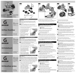
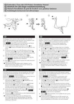
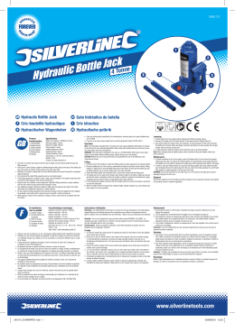
U-05-S Quick Start Guide Guide rapide Kurzanleitung Guida di avvio rapido Snelstartgids Guía de inicio rápido USB D/A Converter Convertisseur D/A USB USB D/A-Wandler Convertitore D/A USB USB D/A-omzetter Convertidor D/A de USB Thank you for buying this Pioneer product. This Quick Start Guide includes instructions for basic connections and operations to allow simple use of the receiver. For detailed descriptions of the receiver, see the “Operating Instructions” provided on the included CD-ROM ( ). Merci pour l’achat de ce produit Pioneer. Ce guide rapide contient les instructions relatives aux raccordements et opérations de base permettant une utilisation simple de ce récepteur. Pour des descriptions plus détaillées du récepteur, référez-vous au “Mode d’emploi” sur le CD-ROM ( ) fourni. What’s in the box • Remote control x 1 • Telecomando x 1 • Type AAA manganese batteries x 2 • Batterie al manganese di tipo AAA x 2 • Power cord • Cavo di alimentazione • Warranty card • Documento di garanzia • Operating Instructions (CD-ROM) • Istruzioni per l’uso (CD-ROM) • Quick Start Guide (this document) • Guida di avvio rapido (questo documento) Contenu de la boîte Vielen Dank, dass Sie sich für dieses Pioneer-Produkt entschieden haben. Die Kurzanleitung enthält Anweisungen für grundlegende Verbindungen und Bedienvorgänge, um eine einfache Bedienung des Receivers zu ermöglichen. Detaillierte Beschreibungen des Receivers finden Sie in der „Bedienungsanleitung“ auf der mitgelieferten CD-ROM ( ). Vi ringraziamo per avere acquistato questo prodotto Pioneer. Questa Guida di avvio rapido comprende istruzioni per i collegamenti fondamentali e per le operazioni essenziali di questo ricevitore. Per una descrizione dettagliata del ricevitore, vedere le “Istruzioni per l’uso” contenute nel CD-ROM ( ) accluso. Hartelijk dank voor de aanschaf van dit Pioneer product. In deze snelstartgids vindt u de instructies voor de basisaansluitingen en de basisbediening voor een eenvoudig gebruik van de receiver. Voor meer gedetailleerde informatie wordt u verwezen naar de “Handleiding” die op de bijgeleverde CD-ROM ( ) staat. Contenuto della confezione De inhoud van de verpakking controleren • Télécommande x 1 • Afstandsbediening x 1 • Piles au manganèse de type AAA x 2 • AAA-type mangaanbatterijen x 2 • Cordon d’alimentation • Netsnoer • Carte de garantie • Garantiebewijs • Mode d’emploi (CD-ROM) • Handleiding (CD-ROM) • Guide rapide (ce document) • Snelstartgids (dit document) Überprüfen des mitgelieferten Zubehörs Contenido de la caja • Fernbedienung x 1 • Mando a distancia x 1 • Mangan-Mikrozelle (Größe „AAA“) x 2 • Pilas manganesas del tipo AAA x 2 • Netzkabel • Cable de alimentación • Garantiekarte • Tarjeta de garantía • Bedienungsanleitung (CD-ROM) • Manual de instrucciones (CD-ROM) • Kurzanleitung (dieses Dokument) • Guía de inicio rápido (este manual) Muchas gracias por haber adquirido este producto de Pioneer. Esta Guía de inicio rápido incluye instrucciones para hacer las conexiones y operaciones básicas que le permitirán hacer un uso sencillo del receptor. Para conocer una descripción detallada del receptor, consulte el “Manual de instrucciones” suministrado con el CD-ROM ( ) incluido. CD-ROM USBDAC_U-05_QSG.indb 1 2014/05/22 20:18:32 Connections Rear panel Computer with USB port Connections to components furnished with digital output. Note Caution • When making or changing connections, be sure to turn off the power switch and disconnect the power cord from its AC power outlet. AES/EBU OUT COAXIAL OUT OPTICAL OUT • A dedicated driver may have to be installed in your computer (see “Install the driver” of the operating instructions). USB • Do not connect the power cord until all component and device connections are completed. A type AES/EBU input connector This digital input supports AES/EBU signals in PCM format (up to 192 kHz/24 bits). Coaxial digital cable (75 Ω) Digital balanced cable (110 Ω) Optical digital cable USB cable USB input connector (B type) Supports PCM format signals (to 384kHz/32 bits), and DSD format (to 5.6 MHz). DIGITAL IN connectors These connectors support PCM format signals (up to 192 kHz/24 bits). To AC outlet ANALOG LINE OUT connectors These two output connectors (RCA/ XLR) simultaneously generate signals selected with the INPUT knob. Signals are output when “LINE” is selected with the OUTPUT knob. Power cord (accessory) Selector switch 2 Selector switch 1 Balanced output connector (appearance on unit side; equivalent to XLR-3-31) 1 3 2 1 GND 2 HOT 3 COLD If a power amplifier is connected, when selector switch 1 is set for linked volume (VARIABLE), sound volume can be controlled by the unit. Either set the analog output connector’s output level to fixed (FIX), or volume-linked (VARIABLE). Balanced cable R Pre-main amplifier, etc., furnished with balanced-type input connectors L R Use to switch the phase of the analog output. Note: XLR and RCA signals are switched together. L Pre-main amplifier with RCA (pin plug) input connectors 2 USBDAC_U-05_QSG.indb 2 2014/05/22 20:18:32 Parts names and functions 6 DIRECT button Remote control Press this button to output the input signal as is, without passing through the DSP. 7 Hi-Bit 32 button Press to change the Hi-Bit 32 setting. 8 1 2 Front panel 1 2 a b 3 4 5 6 7 8 9 8 DIMMER button Press to adjust the display’s brightness. 9 FINE +/− buttons 9 Use to finely adjust the headphone volume (this adjustment affects only the headphone output). a DIGI FILTER button Press to change the type of digital filter used. b Up Sample button Press to change the Up Sampling setting. 3 Basic operation 4 1 Turn power ON. Press the front-panel /I STANDBY/ON button. • The power indicator in the center of the button will light. a 5 2 6 b Rotate the front-panel OUTPUT knob. Set to LINE to select the analog output connector. 3 7 Select the desired output connector. Select the desired input source. Rotate the front-panel INPUT knob, or press the corresponding direct input selector button on the remote control. • The selected input will appear in the display window. • DSD data can be played only when using the USB connection. 4 1 STANDBY/ON Use to alternate power status between ON and STANDBY modes. 2 MUTE button During playback, press to temporarily mute the sound. 3 VOL +/− buttons Press these buttons to raise/lower the sound volume. 4 Direct input selector buttons Press one of the USB/COAX/OPT/AES EBU buttons to select the desired source. 5 LOCK RANGE button Press to adjust the DAC locking range. 5 Operate the playback device. 1 /I STANDBY/ON Use to alternate power status between ON and STANDBY modes. When the unit’s power is ON, the power indicator in the center of the button will light. 2 INPUT knob Use to select the input source. The selected source will appear in the display window. 3 DIRECT indicator See “Direct setting” of the operating instructions. d a PHONES GAIN knob Use to adjust the headphones gain. b OUTPUT knob Use to select the type of output, including LINE, and PHONES 1 to PHONES 3. c Headphones connectors (PHONES 1, 2, 3) Use to connect headphones. d FINE ADJUST knob Use to finely adjust the headphone volume (this adjustment affects only the headphone output). 4 Hi-Bit 32 indicator See “Hi-Bit 32 setting” of the operating instructions. For details, consult the operating instructions for your playback device. 5 Up Sampling indicator Adjust the sound volume. 6 LOCK RANGE ADJUST indicator Rotate the unit’s front-panel VOLUME knob, or use the VOL +/− buttons on the remote control. c See “Up Sampling setting” of the operating instructions. See “Adjust the DAC locking range” of the operating instructions. 7 Display window 8 Remote control sensor 9 VOLUME knob In order to control the sound volume of a component connected to the unit’s analog output connector, Selector switch 1 (on unit’s rear panel) must be set to VARIABLE. 3 USBDAC_U-05_QSG.indb 3 2014/05/22 20:18:33 Connexions Panneau arrière Ordinateur à port USB Connexions aux composants munis d’une sortie numérique Remarque Attention • Lorsque vous faites ou modifiez les connexions, prenez soin de couper l’interrupteur secteur et de débrancher le cordon d’alimentation au niveau de sa prise du secteur. AES/EBU OUT COAXIAL OUT OPTICAL OUT USB • Ne branchez pas le cordon d’alimentation tant que toutes les connexions des composants et de l’appareil ne sont pas terminées. Type A Câble symétrique numérique (110 Ω) Connecteur d’entrée AES/EBU • Il se peut qu’un pilote spécifique doive être installé sur votre ordinateur (reportez-vous à la rubrique “Installation du pilote” du mode d’emploi). Câble coaxial numérique (75 Ω) Câble optique numérique Câble USB Connecteur d’entrée USB (type B) Accepte les signaux de format PCM (jusqu’à 384 kHz/32 bits) et de format DSD (jusqu’à 5,6 MHz). Cette entrée numérique accepte les signaux AES/EBU en format PCM (jusqu’à 192 kHz/24 bits). Connecteurs DIGITAL IN Ces connecteurs acceptent les signaux de format PCM (jusqu’à 192 kHz/24 bits). À la prise secteur Connecteur ANALOG LINE OUT Ces deux connecteurs de sortie (RCA/ XLR) fournissent simultanément les signaux sélectionnés par le bouton INPUT. Les signaux sont sortis quand “LINE” est sélectionné par le bouton OUTPUT. Cordon d’alimentation (accessoire) Sélecteur 2 Sélecteur 1 Connecteur de sortie symétrique (aspect sur côté appareil ; équivalent au XLR-3-31) 1 3 2 1 GND (masse) 2 HOT (chaud) 3 COLD (froid) Si un ampli de puissance est raccordé, lorsque le Sélecteur 1 est réglé en fonction du volume (VARIABLE), le volume sonore pourra être contrôlé par l’appareil. Réglez le niveau de sortie du connecteur de sortie analogique soit sur Fixe (FIX), soit sur Tributaire du volume (VARIABLE). Câble symétrique R Pré-ampli, ampli principal, etc., munis de connecteurs d’entrée symétriques L R Il permet de commuter la phase de la sortie analogique. Remarque : Les signaux XLR et RCA sont commutés ensemble. L Pré-ampli, ampli principal à connecteurs d’entrée RCA (broche) 2 USBDAC_U-05_QSG.indb 2 2014/05/22 20:18:33 Noms des organes et leurs fonctions 6 Bouton DIRECT Télécommande Appuyez sur ce bouton pour fournir le signal d’entrée tel quel, sans passer par DSP. 7 Bouton Hi-Bit 32 Appuyez pour changer le réglage Hi-Bit 32. 8 1 2 Panneau avant 1 2 a b 3 4 5 6 7 8 9 8 Bouton DIMMER Appuyez pour ajuster la luminosité de l’affichage. 9 Boutons FINE +/− A utiliser pour ajuster avec précision le volume au casque (ce réglage affecte seulement la sortie du casque). 9 a Bouton DIGI FILTER Appuyez pour changer le type de filtre numérique utilisé. 3 b Bouton d’échantillonnage (Up Sample) Appuyez pour modifier le réglage d’échantillonnage. 4 Démarches de base a 5 6 1 • Le voyant d’alimentation au centre du bouton s’allume. 2 7 Choisissez le connecteur de sortie souhaité. Actionnez le bouton OUTPUT du panneau avant. Réglez sur LINE pour choisir le connecteur de sortie analogique. 3 Choisissez la source d’entrée souhaitée. Actionnez le bouton INPUT du panneau avant, ou appuyez sur le sélecteur d’entrée directe sur la télécommande. • L’entrée choisie apparaîtra sur la fenêtre d’affichage. 1 STANDBY/ON Il permet d’alterner l’alimentation entre le mode ON (sous tension) et STANDBY (en attente). 2 Bouton MUTE Pendant la lecture, sa pression met temporairement le son en sourdine. 3 Boutons VOL +/− Appuyez sur ces boutons pour augmenter / diminuter le volume sonore. 4 Sélecteurs d’entrée directe • Les données DSD seront reproduites seulement à l’emploi de la connexion USB. 4 Faites fonctionner le composant de lecture. Pour plus de détails, consultez le mode d’emploi du composant de lecture. 5 d Mise sous tension. Appuyez sur le bouton /I STANDBY/ON du panneau avant. b c Réglez le volume sonore. Agissez sur le bouton VOLUME du panneau avant de l’appareil ou servez-vous des boutons VOL +/− sur la télécommande. 1 /I STANDBY/ON Il permet d’alterner l’alimentation entre le mode ON (sous tension) et STANDBY (en attente). Quand l’appareil est sous tension (ON), le voyant au centre du bouton s’allume. 2 Bouton INPUT A utiliser pour sélectionner la source d’entrée. La source choisie apparaîtra sur la fenêtre d’affichage. 3 Voyant DIRECT Reportez-vous à la rubrique “Réglage Direct” du mode d’emploi. 4 Voyant Hi-Bit 32 Reportez-vous à la rubrique “Réglage Hi-Bit 32” du mode d’emploi. 5 Voyant d’échantillonnage Reportez-vous à la rubrique “Réglage d’échantillonage” du mode d’emploi. 9 Bouton VOLUME Pour contrôler le volume sonore d’un composant raccordé au connecteur de sortie analogique de l’appareil, le Sélecteur 1 (sur le panneau arrière de l’appareil) doit être réglé sur VARIABLE. a Bouton PHONES GAIN A utiliser pour ajuster le gain au casque. b Bouton OUTPUT A utiliser pour choisir le type de sortie, notamment LINE, et de PHONES 1 à PHONES 3. c Connecteurs de casque (PHONES 1, 2, 3) Pour connecter un casque d’écoute. d Bouton FINE ADJUST A utiliser pour ajuster avec précision le volume au casque (ce réglage affecte seulement la sortie du casque). 6 Voyant LOCK RANGE ADJUST Reportez-vous à la rubrique “Réglage de la portée de blocage DAC” du mode d’emploi. 7 Fenêtre d’affichage 8 Capteur de télécommande Appuyez sur un des boutons USB/COAX/OPT/AES EBU pour sélectionner la source souhaitée. 5 Bouton LOCK RANGE Appuyez pour ajuster la plage de blocage DAC. 3 USBDAC_U-05_QSG.indb 3 2014/05/22 20:18:33 Anschlüsse Rückwand Computer mit USB-Anschluss Anschlüsse an Komponenten mit digitaler Ausgangsbuchse. Hinweis Achtung • Achten Sie stets darauf, den Netzschalter auszuschalten und den Netzstecker von der Netzsteckdose zu trennen, bevor Sie irgendwelche Anschlüsse herstellen oder ändern. AES/EBU OUT COAXIAL OUT OPTICAL OUT USB • Schließen Sie das Netzkabel erst dann an, nachdem alle anderen Anschlüsse hergestellt worden sind. Typ A Symmetrisches Digitalkabel (110 Ω) AES/EBU-Eingangsbuchse • Die Installation eines Spezialtreibers auf dem Computer kann erforderlich sein (siehe den Abschnitt „Installieren Sie den Treiber“ in der Bedienungsanleitung). Optisches Digitalkabel Koaxiales Digitalkabel (75 Ω) USB-Kabel USB-Eingangsbuchse (Typ B) Diese Buchse unterstützt Signale im PCM-Format (bis 384 kHz/32 Bit) und DSD-Format (bis 5,6 MHz). Dieser Digitaleingang unterstützt AES/ EBU-Signale des PCM-Formats (bis zu 192 kHz/24 Bit). DIGITAL IN-Buchsen Diese Buchsen unterstützen Signal des PCM-Formats (bis zu 192 kHz/24 Bit). An Steckdose ANALOG LINE OUT-Buchsen An diesen beiden zwei Paaren von Ausgangsbuchsen (Cinch/XLR) liegen die mit INPUT-Regler gewählten Signale gleichzeitig an. Die Signale werden ausgegeben, wenn “LINE” mit dem OUTPUT-Regler gewählt ist. Netzkabel (mitgeliefert) Wahlschalter 2 Wahlschalter 1 Dient zur Einstellung des Ausgangspegels der analogen Ausgangsbuchsen entweder auf den Festwert (FIX) oder auf Verknüpfung mit dem Lautstärkepegel (VARIABLE). Symmetrische Ausgangsbuchse (Aussehen am Gerät; gleichwertig mit XLR-3-31) 1 3 2 1 Masse 2 Stromführend 3 Nicht stromführend Wenn ein Leistungsverstärker angeschlossen und Wahlschalter 1 auf Verknüpfung mit dem Lautstärkepegel (VARIABLE) eingestellt ist, kann die Lautstärke an diesem Gerät geregelt werden. Symmetrisches Kabel R Vorverstärker usw. mit symmetrischen Eingangsbuchsen L R Dient zur Umschaltung der Phase des Analogausgangs. Hinweis: Die Phase der an den XLRund Cinch-Ausgangsbuchsen anliegenden Signale wird gleichzeitig umgeschaltet. L Vorverstärker usw. mit CinchEingangsbuchsen 2 USBDAC_U-05_QSG.indb 2 2014/05/22 20:18:33 Bezeichnungen und Funktionen der Teile 6 Taste DIRECT Fernbedienung Drücken Sie diese Taste, um das Eingangssignal unverändert auszugeben, ohne die DSP-Schaltung zu passieren. 8 1 2 7 Taste Hi-Bit 32 Frontplatte 1 2 a b 3 4 5 6 7 8 9 Drücken Sie diese Taste, um die Hi-Bit 32-Einstellung zu ändern. 8 Taste DIMMER Drücken Sie diese Taste, um die Helligkeit des Displays einzustellen. 9 9 Tasten FINE +/− Diese Taste dient zur Feinjustierung der Kopfhörerlautstärke (nur das an den Kopfhörer ausgegebene Signal wird von dieser Einstellung beeinflusst). 3 a Taste DIGI FILTER Betätigen Sie diese Taste, um die Art des verwendeten Digitalfilters zu ändern. 4 b Taste Up Sample a 5 c 1 Netzschalter /I STANDBY/ON 6 Grundlegende Bedienungsverfahren b 1 Schalten Sie das Gerät ein. Drücken Sie den Netzschalter /I STANDBY/ON an der Frontplatte. 7 • Die Einschaltanzeige in der Mitte des Schalters leuchtet auf. 2 3 Drücken Sie diese Taste während der Wiedergabe, um den Ton vorübergehend stummzuschalten. • Die gewählte Eingangsquelle wird im Display angezeigt. 3 Lautstärkeregeltasten VOL +/− • DSD-Daten können wiedergegeben werden, wenn ein USB-Anschluss hergestellt ist. 4 4 Tasten für direkte Eingangswahl Drücken Sie eine der Tasten USB/COAX/OPT/AES EBU, um die entsprechende Eingangsquelle zu wählen. 5 Verriegelungsbereich-Taste LOCK RANGE Drücken Sie diese Taste, um den DACVerriegelungsbereich einzustellen. USBDAC_U-05_QSG.indb 3 Wählen Sie die gewünschte Eingangsquelle. Drehen Sie den INPUT-Regler an der Frontplatte oder drücken Sie die entsprechende Taste für direkte Eingangswahl an der Fernbedienung. 2 Stummschaltungstaste MUTE Betätigen Sie diese Tasten, um die Lautstärke zu erhöhen oder zu verringern. Wählen Sie den gewünschten Ausgang. Drehen Sie den OUTPUT-Regler an der Frontplatte. Zur Wahl der analogen Ausgangsbuchsen stellen Sie den Regler auf LINE ein. 1 Netzschalter STANDBY/ON Bei jeder Betätigung dieses Schalters wird das Gerät abwechselnd ein- und in den Bereitschaftszustand umgeschaltet d Drücken Sie diese Taste, um die Einstellung der Abtastfrequenz-Erhöhung zu ändern. 5 Starten Sie die Wiedergabe am Wiedergabegerät. Bei jeder Betätigung dieses Schalters wird das Gerät abwechselnd ein- und in den Bereitschaftszustand umgeschaltet Im Einschaltzustand des Gerätes leuchtet die Einschaltanzeige in der Mitte des Schalters. 2 INPUT-Regler Dieser Regler dient zur Wahl der gewünschten Signalquelle. Die momentan gewählte Eingangsquelle wird im Display angezeigt. 3 DIRECT-Anzeige Siehe den Abschnitt „Direkteinstellung“ in der Bedienungsanleitung. 4 Hi-Bit 32-Anzeige Siehe den Abschnitt „Hi-Bit 32-Einstellung“ in der Bedienungsanleitung. 5 Up Sampling-Anzeige Siehe den Abschnitt „Einstellung der AbtastfrequenzErhöhung“ in der Bedienungsanleitung. Um den Lautstärkepegel einer an die analogen Ausgangsbuchsen dieses Gerätes angeschlossenen Komponente regeln zu können, muss Wahlschalter 1 (an der Rückwand des Gerätes) auf VARIABLE eingestellt sein. a PHONES GAIN-Regler Dieser Regler dient zur Einstellung der Verstärkung des Kopfhörers. b OUTPUT-Regler Dieser Regler dient zur Wahl der Art des Ausgangs, einschließlich von LINE und PHONES 1 bis PHONES 3. c Kopfhörerbuchsen (PHONES 1, 2, 3) Hier kann ein Kopfhörer angeschlossen werden. d FINE ADJUST-Regler Dieser Regler dient zur Feinjustierung der Kopfhörerlautstärke (nur das an den Kopfhörer ausgegebene Signal wird von dieser Einstellung beeinflusst. 6 LOCK RANGE ADJUST-Anzeige Siehe den Abschnitt „Einstellung des DACVerriegelungsbereichs“ in der Bedienungsanleitung. Einzelheiten hierzu finden Sie in der Bedienungsanleitung des jeweiligen Wiedergabegerätes. 7 Display Erhöhen Sie den Lautstärkepegel. 8 Fernbedienungssignal-Sensor Drehen Sie den VOLUME-Regler an der Frontplatte oder betätigen Sie die Tasten VOL +/− an der Fernbedienung. 9 Lautstärkeregler VOLUME 3 2014/05/22 20:18:33 Collegamenti Pannello posteriore Computer dotato di porta USB Collegamento a componenti dotati di uscita digitale. Nota Attenzione • Prima di fare o modificare i collegamenti, spegnere sempre l’apparecchio e scollegare il cavo di alimentazione dalla presa di corrente alternata. AES/EBU OUT COAXIAL OUT OPTICAL OUT • Il vostro computer potrebbe richiedere l’installazione di un driver apposito (vedere “Installare il driver” nelle istruzioni per l’uso). USB • Non collegare il cavo di alimentazione se non dopo che tutti i dispositivi e collegamenti sono stati completati. Tipo A Connettore di ingresso AES/EBU Questo ingresso digitale supporta segnali AES/EBU di formato PCM (da fino a 192 kHz/24 bit). Cavo digitale a fibre ottiche Cavo digitale coassiale (75 Ω) Cavo digitale bilanciato (110 Ω) Cavo USB Connettore di ingresso USB (tipo B). Supporta segnale di formato PCM (fino a 384 kHz/32 bit), e DSD (fino a 5,6 MHz). Connettori DIGITAL IN Questi connettori supportano segnale di formato PCM (da fino a 192 kHz/24 bit). Ad una presa CA Connettori ANALOG LINE OUT Questi due connettori (RCA/XLR) generano simultaneamente il segnale scelto con la manopola INPUT. Il segnale viene emesso quando “LINE” viene scelto con la manopola OUTPUT. Cavo di alimentazione (accessorio) Selettore 2 Selettore 1 Connettore di uscita bilanciato (sul lato dell’unità, equivalente ad un XLR-3-31). Cavo bilanciato 1 TERRA 1 3 Regolare il livello di uscita del connettore analogico di uscita su fisso (FIX) o legato al volume (VARIABLE). 2 2 CONDUTTORE Consente di cambiare la fase dell’uscita analogica. Nota: I segnali XLR e RCA vengono commutati insieme. 3 NON CONDUTTORE Se si è collegato un amplificatore di potenza, col selettore 1 sulla posizione legata al volume (VARIABLE) il volume può essere controllato da questa unità. R Preamplificatore , amplificatore, ecc. dotato di connettori di uscita di tipo bilanciato. L R L Preamplificatore con connettori di ingresso per spinotti RCA 2 USBDAC_U-05_QSG.indb 2 2014/05/22 20:18:33 Nome delle parti e loro funzione 6 Pulsante DIRECT Telecomando Premere questo pulsante per emettere il segnale come è senza farlo passare per il DSP. 7 Pulsante Hi-Bit 32 Premerlo per cambiare l’impostazione Hi-Bit 32. 8 1 2 Pannello anteriore 1 2 a b 3 4 5 6 7 8 9 8 Pulsante DIMMER Consente di regolare la luminosità del display. 9 Pulsanti FINE +/− 9 Consentono di regolare in modo fine il volume in cuffia (questa regolazione influenza solo il volume in cuffia). a Pulsante DIGI FILTER Consente di cambiare il tipo di filtro digitale usato. b Pulsante Up Sample Consente di cambiare l’impostazione Up Sampling 3 Uso di base 4 1 a 5 6 b 7 Accendere l’apparecchio. Premere il pulsante /I STANDBY/ON del pannello anteriore. • L’indicatore di alimentazione al centro del pulsante si accende. 2 Scegliere il connettore di uscita desiderato. Girare la manopola OUTPUT del pannello anteriore. Scegliere LINE per scegliere il connettore di uscita analogico. 3 Scegliere la sorgente di segnale desiderata. Girare la manopola INPUT del pannello anteriore o premere il selettore di ingresso diretto del telecomando. • La sorgente scelta appare nella finestra del display. 1 STANDBY/ON Consente di alternare le modalità ON e STANDBY. • I dati DSD possono essere riprodotti solo usando un connettore USB. 4 2 Pulsante MUTE Se premuto durante la riproduzione, consente di farla tacere temporaneamente. 3 Pulsanti VOL +/− Premere questi per aumentare/diminuire il volume. 4 Selettori diretti di ingresso Premere un pulsante fra USB/COAX/OPT/AES EBU per scegliere la sorgente di segnale desiderata. 5 Pulsante LOCK RANGE Consente di regolare la gamma di bloccaggio DAC. Azionare il dispositivo di riproduzione. Per dettagli, consultare il manuale del dispositivo di riproduzione. 5 Regolare il volume audio. Girare la manopola VOLUME del pannello anteriore o i pulsanti VOL +/− del telecomando. c 1 /I STANDBY/ON Consente di alternare le modalità di alimentazione ON e STANDBY. Quando l’unità è accesa, l’indicatore di alimentazione al centro del pulsante si accende. 2 Manopola INPUT Consente di cambiare l’ingresso scelto. La sorgente scelta appare nella finestra del display. 3 Indicatore DIRECT Vedere “Impostazione Direct” nelle istruzioni per l’uso. d a Manopola PHONES GAIN Consente di regolare il guadagno della cuffia. b Manopola OUTPUT Consente di scegliere il tipo di uscita, compresi LINE e da PHONES 1 a PHONES 3. c Connettori per cuffie (PHONES 1, 2, 3) Utilizzare per collegare le cuffie. d Manopola FINE ADJUST Consentono di regolare in modo fine il volume in cuffia (questa regolazione influenza solo il volume in cuffia). 4 Indicatore Hi-Bit 32 Vedere “Impostazione Hi-Bit 32” nelle istruzioni per l’uso. 5 Indicatore Up Sampling Vedere “Impostazione Up Sampling” nelle istruzioni per l’uso. 6 Indicatore LOCK RANGE ADJUST Vedere “Regolazione della gamma DAC” nelle istruzioni per l’uso. 7 Finestra del display 8 Sensore di telecomando 9 Manopola VOLUME Per controllare il volume di un componente collegato al connettore di uscita analogica di questa unità, il Selettore 1 (sul pannello posteriore) deve essere regolato su VARIABLE. 3 USBDAC_U-05_QSG.indb 3 2014/05/22 20:18:33 Aansluitingen Achterpaneel Computer met USB-poort Aansluiten op apparatuur uitgerust met een digitale uitgang. Opmerking Let op • Voordat u aansluitingen maakt of wijzigt, moet u de stroom uitschakelen en de stekker van het netsnoer uit het stopcontact trekken. AES/EBU OUT COAXIAL OUT OPTICAL OUT • Het is mogelijk dat op uw computer een speciaal stuurprogramma moet worden geïnstalleerd (zie “Het stuurprogramma installeren” van de handleiding). USB • Steek de stekker van het netsnoer pas in het stopcontact nadat alle aansluitingen zijn voltooid. Type A AES/EBU ingangsaansluiting Deze digitale ingang ondersteunt AES/ EBU-signalen in PCM-formaat (tot 192 kHz/24 bit). Digitale gebalanceerde kabel (110 Ω) Coaxiale digitale kabel (75 Ω) Optische digitale kabel USB-kabel USB ingangsaansluiting (type B) Ondersteunt PCM-formaat signalen (tot 384 kHz / 32 bit) en DSD-formaat (tot 5,6 MHz). DIGITAL IN aansluitingen Deze aansluitingen ondersteunen PCM-formaat signalen (tot 192 kHz/ 24 bit). Naar stopcontact ANALOG LINE OUT aansluitingen Deze twee uitgangsaansluitingen (RCA/XLR) genereren gelijktijdig de signalen die met de INPUT knop worden gekozen. De signalen worden uitgevoerd wanneer “LINE” is gekozen met de OUTPUT knop. Netsnoer (bijgeleverd) Keuzeschakelaar 2 Keuzeschakelaar 1 Gebalanceerde uitgangsaansluiting (aanzicht aan apparaatzijde; gelijkwaardig aan XLR-3-31) 1 3 Kies vast ingesteld niveau (FIX) of volume-gekoppeld niveau (VARIABLE) voor het uitgangsniveau van de analoge uitgangsaansluiting. Gebalanceerde kabel 1 AARDE 2 2 SPANNING Gebruik deze schakelaar om de fase van de analoge uitgang om te schakelen. Opmerking: XLR- en RCA-signalen worden tegelijk omgeschakeld. 3 GEEN SPANNING Als een eindversterker is aangesloten en keuzeschakelaar 1 is ingesteld op volume-gekoppeld niveau (VARIABLE), kan het geluidsvolume op het apparaat worden ingesteld. R Voor/eindversterker enz. uitgerust met gebalanceerd-type ingangsaansluitingen L R L Voor/eindversterker met RCA (penstekker) ingangsaansluitingen 2 USBDAC_U-05_QSG.indb 2 2014/05/22 20:18:33 Overzicht van de bedieningstoetsen 6 DIRECT toets Afstandsbediening Druk hierop om het ingangssignaal ongewijzigd uit te voeren, dus zonder dat dit via de DSP loopt. 7 Hi-Bit 32 toets Druk hierop om de Hi-Bit 32 instelling te veranderen. 8 1 2 Voorpaneel 1 2 a b 3 4 5 6 7 8 9 8 DIMMER toets (Dimtoets) Druk hierop om de helderheid van het display te veranderen. 9 FINE +/− toetsen (Fijnafsteltoetsen) 9 Gebruik deze voor fijnafstelling van het hoofdtelefoonvolume (deze afstelling is alleen van invloed op het hoofdtelefoon-uitgangsniveau). a DIGI FILTER toets (Toets voor digitaal filter) Druk hierop om het gebruikte type digitaal filter te veranderen. 3 b Up Sample toets (Bemonsteringverhogingstoets) 4 Druk hierop om de instelling voor verhoging van de bemonsteringsfrequentie te veranderen. a 5 6 b Basisbediening 1 Schakel het apparaat in. Druk op de /I STANDBY/ON toets op het voorpaneel. • De spanningsindicator in het midden van het toets licht op. 7 2 Kies de gewenste uitgangsaansluiting. Draai aan de OUTPUT knop op het voorpaneel. Stel in op LINE om de analoge uitgangsaansluiting te kiezen. 3 1 STANDBY/ON Gebruik deze toets voor het omschakelen tussen ON (aan) en STANDBY (ruststand). • De gekozen ingangsbron wordt op het display aangegeven. 2 MUTE toets (Dempingstoets) Druk tijdens weergave op deze toets om het geluid tijdelijk uit te schakelen. • DSD-gegevens kunnen alleen worden weergegeven bij gebruik van de USB-verbinding. 4 3 VOL +/− toetsen (Volumetoetsen) Druk op deze toetsen om het geluidsvolume te verhogen/verlagen. 4 Directe ingangskeuzetoetsen Druk op een van de USB/COAX/OPT/AES EBU toetsen om de gewenste ingangsbron te kiezen. Kies de gewenste ingangsbron. Draai aan de INPUT knop op het voorpaneel of druk op de corresponderende directe ingangskeuzetoets op de afstandsbediening. Bedien het weergaveapparaat. Raadpleeg voor verdere informatie de handleiding die bij het weergaveapparaat wordt geleverd. 5 Stel het geluidsvolume in. Draai aan de VOLUME knop op het voorpaneel van het apparaat of gebruik de VOL +/− toetsen op de afstandsbediening. c 1 /I STANDBY/ON Gebruik deze toets voor het omschakelen tussen ON (aan) en STANDBY (ruststand). Wanneer het apparaat is ingeschakeld, licht de spanningsindicator in het midden van de toets op. 2 INPUT knop (Ingangskeuzeknop) Gebruik deze knop om de ingangsbron te kiezen. De gekozen bron wordt op het display aangegeven. 3 DIRECT indicator Zie “Direct-instelling” van de handleiding. 4 Hi-Bit 32 indicator Zie “Hi-Bit 32 instelling” van de handleiding. 5 Up Sampling indicator (Indicator voor bemonstering-verhoging) Zie “Instelling voor bemonstering-verhoging” van de handleiding. 6 LOCK RANGE ADJUST indicator (Indicator voor instelling van blokkeerbereik) Zie “Het DAC-blokkeerbereik instellen” van de handleiding. d 9 VOLUME knop (Volumeknop) Om het geluidsvolume in te stellen van apparatuur aangesloten op de analoge uitgangsaansluiting van het apparaat, moet de Keuzeschakelaar 1 (op het achterpaneel van het apparaat) op VARIABLE worden ingesteld. a PHONES GAIN knop (Hoofdtelefoonversterkingsknop) Gebruik deze knop om de versterking van de hoofdtelefoon in te stellen. b OUTPUT knop (Uitgangsknop) Gebruik deze knop om het type uitgang, waaronder LINE en PHONES 1 t/m PHONES 3, te kiezen. c Hoofdtelefoonaansluitingen (PHONES 1, 2, 3) Sluit hierop een hoofdtelefoon aan. d FINE ADJUST knop (Fijnafstelknop) Gebruik deze voor fijnafstelling van het hoofdtelefoonvolume (deze afstelling is alleen van invloed op het hoofdtelefoon-uitgangsniveau). 7 Displayvenster 8 Afstandsbedieningssensor 5 LOCK RANGE toets (Blokkeerbereiktoets) Druk hierop om het DAC-blokkeerbereik in te stellen. 3 USBDAC_U-05_QSG.indb 3 2014/05/22 20:18:33 Conexiones Panel posterior Ordenador con puerto USB Conexiones con componentes provistos de salida digital. Nota Precaución • Cuando desee realizar o cambiar conexiones, no se olvide de desconectar antes el interruptor de la alimentación y de desenchufar el cable de alimentación de la toma de corriente de CA. AES/EBU OUT COAXIAL OUT OPTICAL OUT USB • No enchufe el cable de alimentación hasta haber terminado todas las conexiones de los componentes y de los dispositivos. Conector de entrada AES/EBU Esta entrada digital es compatible con señales AES/EBU en el formato PCM (hasta 192 kHz/24 bits). • Es posible que deba instalar un controlador exclusivo en el ordenador (consulte “Instalación del controlador” en el manual de instrucciones). Tipo A Cable digital equilibrado (110 Ω) Cable digital coaxial (75 Ω) Cable digital óptico Cable USB Conector de entrada USB (tipo B) Es compatible con las señales del formato PCM (hasta 384 kHz/32 bits) y del formato DSD (hasta 5,6 MHz). Conectores de entrada digital (DIGITAL IN) Estos conectores son compatibles con señales del formato PCM (hasta 192 kHz/24 bits). A una toma de corriente de CA Conectores de salida de línea analógica (ANALOG LINE OUT) Estos dos conectores de salida (RCA/ XLR) generan simultáneamente señales seleccionadas con el mando INPUT. Las señales se emiten cuando se selecciona “LINE”con el mando OUTPUT. Cable de alimentación (accesorio) Selector 2 Selector 1 Ajuste el nivel de salida del conector de salida analógica en el ajuste fijo (FIX) o en el ajuste enlazado con el volumen (VARIABLE). Conector equilibrado de salida (aspecto en el lado de la unidad; equivalente a XLR-3-31) 1 3 2 1 MASA 2 CALIENTE 3 FRÍO Cable equilibrado Si se ha conectado un amplificador de potencia, cuando el selector 1 está ajustado en el ajuste enlazado con el volumen (VARIABLE), Preamplificador principal, etc. provisto el volumen del sonido podrá de conectores de entrada del tipo controlarse con la unidad. equilibrado. R L R Se emplea para cambiar la fase de la salida analógica. Nota: Las señales XLR y RCA se cambian al mismo tiempo. L Preamplificador principal con conectores de entrada RCA (clavija). 2 USBDAC_U-05_QSG.indb 2 2014/05/22 20:18:34 Nombres y funciones de los controles 5 Botón LOCK RANGE Mando a distancia Púlselo para ajustar la gama de bloqueo de DAC. Panel frontal 6 Botón DIRECT Pulse este botón para emitir la señal de entrada tal y como está, sin que pase por el DSP. 8 1 2 1 2 a b 3 4 5 6 7 8 9 7 Botón Hi-Bit 32 Púlselo para cambiar el ajuste de Hi-Bit 32. 8 Botón DIMMER Púlselo para ajustar el brillo del visualizador. 9 9 Botones FINE +/− Utilícelos para ajustar con precisión el volumen de los auriculares (este ajuste sólo afecta la salida de auriculares). a Botón DIGI FILTER 3 Púlselo para cambiar el tipo de filtro digital utilizado. b Botón Up Sample Púlselo para cambiar el ajuste de incremento de muestreo. 4 a 5 b 7 Conecte la alimentación. Pulse el botón /I STANDBY/ON del panel frontal. • El indicador de alimentación que hay en el centro del botón se encenderá. 2 Seleccione el conector de salida deseado. Gire el mando OUTPUT del panel frontal. Ajústelo en LINE para seleccionar el conector de salida analógica. 3 • La entrada seleccionada aparecerá en la ventana de visualización. Se emplea para alternar el estado de la alimentación entre los modos de estado de funcionamiento (ON) y de espera (STANDBY). Púlselo durante la reproducción para silenciar temporalmente el sonido. 3 Botones VOL +/− Pulse estos botones para subir/bajar el volumen del sonido. 4 Botones del selector de entrada directa Pulse uno de los botones USB/COAX/OPT/AES EBU para seleccionar la fuente deseada. Seleccione la fuente de entrada que desee. Gire el mando INPUT del panel frontal o pulse el botón del selector de entrada directa correspondiente en el mando a distancia. 1 STANDBY/ON 2 Botón MUTE d Operación básica 1 6 c • Los datos DSD sólo pueden reproducirse cuando se emplea la conexión USB. 4 Opere el dispositivo de reproducción. Con respecto a los detalles, consulte el manual de instrucciones de su dispositivo de reproducción. 5 Ajuste el volumen del sonido. Gire el mando VOLUME del panel frontal o emplee los botones VOL +/− del mando a distancia. 1 /I STANDBY/ON Se emplea para alternar el estado de la alimentación entre los modos de estado de funcionamiento (ON) y de espera (STANDBY). Cuando la alimentación de la unidad está conectada (ON), se enciende el indicador de encendido que hay en el centro del botón. 2 Mando INPUT Se emplea para seleccionar la fuente de entrada. La fuente seleccionada aparecerá en la ventana de visualización. 3 Indicador DIRECT Consulte “Ajuste directo” en el manual de instrucciones. 4 Indicador Hi-Bit 32 Consulte “Ajuste de Hi-Bit 32” en el manual de instrucciones. 5 Indicador Up Sampling 9 Mando VOLUME Para controlar el volumen del sonido de un componente conectado al conector de salida analógica de la unidad, el Selector 1 (del panel posterior de la unidad) debe estar ajustado en VARIABLE. a Mando PHONES GAIN Utilícelo para ajustar la ganancia de los auriculares. b Mando OUTPUT Utilícelo para seleccionar el tipo de salida, incluyendo LINE, y PHONES 1 a PHONES 3. c Conectores de auriculares (PHONES 1, 2, 3) Utilícelos para conectar los auriculares. d Mando FINE ADJUST Utilícelos para ajustar con precisión el volumen de los auriculares (este ajuste sólo afecta la salida de auriculares). Consulte “Ajuste del incremento de muestreo” en el manual de instrucciones. 6 Indicador LOCK RANGE ADJUST Consulte “Ajuste de la gama de bloqueo de DAC” en el manual de instrucciones. 7 Ventana de visualización 8 Sensor del mando a distancia 3 USBDAC_U-05_QSG.indb 3 2014/05/22 20:18:34 4 USBDAC_U-05_QSG.indb 4 2014/05/22 20:18:34 5 USBDAC_U-05_QSG.indb 5 2014/05/22 20:18:34 / USBDAC_U-05_QSG.indb 6 <5707-00000-931-0S> 2014/05/22 20:18:34
Scaricare