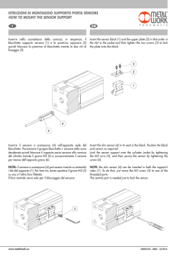
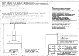
Manuale di installazione sensore di flusso TFTHP
TFTHP fuel flow sensor installation manual
Versione documento/Document version: 1.2 – 23/9/2013
Il sensore TFTHP è adatto a misurare un flusso a basse portate grazie alla sua turbina ad elica ultra leggera e al
cuscinetto in rubino. Ha un'alta resistenza a prodotti chimici corrosivi e agli idrocarburi. La custodia permette il controllo
periodico del tubo sensore ed eventualmente la sua sostituzione.
NOTA: Il sensore è utilizzabile esclusivamente abbinato a strumenti Flybox®.
The TFTHP flowmeter is developed to measure low range of fuel flow with high resolution output. It has high chemical
resistance and it is suitable for aggressive liquids. The case can be opened for periodic monitoring and eventual
replacement of the tube.
NOTE: This sensor can only be used in combination with a Flybox® instrument.
Raccomandazioni di installazione e uso / Recommendation of installation and use:
•
•
•
•
•
•
•
•
•
•
•
•
•
Rispettare la direzione del flusso indicata dalla freccia sul sensore.
Check flow direction (arrow on sensor).
Non soffiare nel sensore con aria compressa.
Never clean the sensor with compressed air.
Installare un filtro sulla linea carburante prima del sensore.
Install a filter in the fuel line before the sensor.
Oliare i raccordi prima di montare i tubi.
Oil the fittings before mounting the tubes.
I tubi prima e dopo il sensore devono essere dritti per almeno 5 cm.
The tubes before and after the sensor should be straight for 5 cm.
Le connessioni del sensore di flusso sono adatte a tubi da 6 mm.
Connections of fuel flow sensor are suitable for 6 mm tubes.
Usare esclusivamente fascette a molla del tipo qui raffigurato, con diametro appropriato,
in modo da non deformare i portagomma.
Use only spring band clamps of the type depicted here, with the appropriate
diameter, in order to avoid deformation of the plastic fittings.
Proteggere il sensore dalle alte temperature con una guaina termica.
Protect the sensor from high temperature with a firesleeve material.
Controllare eventuali perdite prima della messa in moto e dell'utilizzo in volo.
Check for leakage after system start.
Ispezionare il sensore ogni 100 ore di volo o una volta all'anno, controllandone l'invecchiamento ed
eventuali perdite.
Per ispezionare il sensore, aprirlo separando il tubo sensore dal corpo nero e scollegarlo dall'impianto
carburante. Guardare all'interno dei due raccordi plastici verificandone l'invecchiamento, l'integrità del
materiale ed eventuali deformazioni meccaniche. In caso di qualsiasi anomalia al tubo sensore, esso andrà
sostituito.
Verificare che l'interno del tubo sensore sia pulito e privo di detriti di qualsiasi tipo. Se necessario pulirlo con un
flusso di benzina in direzione opposta a quella indicata dalla freccia sul corpo nero.
Inspect the fuel sensor every year or every 100 hours of aircraft use for leakage and aging.
To inspect and clean the sensor, open it, remove the sensor tube from the fuel system and look
inside the two fittings to check for material integrity, aging and deformation. In case of any anomaly
of the sensor tube, it must be replaced. Verify that the sensor tube is clean and without any
obstruction. If necessary clean with a flow of fuel in the opposite direction.
Il sensore di flusso si installa prima del carburatore e dopo l'eventuale linea di ritorno (Vapour lock).
The fuel flow transducer must be installed before the carburetor and after the eventual return line
(Vapor lock).
Non fissarlo meccanicamente alla struttura del velivolo per evitare danneggiamenti dovuti alle vibrazioni.
Don't fix it mechanically to the airplane structure to avoid vibrations damage.
Deve essere montato più in basso rispetto al carburatore o al limite non più alto di 10 cm ogni 30.
Mount the transducer lower than the carburetor, or no more higher than 10 cm every 30.
Connessioni elettriche
Electrical wiring
Misure meccaniche
Dimensions
Dati tecnici – Technical specifications
Portata min/ max - Flow range
0,06 – 2,0 l/min
Accuratezza - Accuracy
1%
Ripetibilità - Repeability
0,15%
Materiale parti bagnate - Wetted parts
Teflon/cuscinetto in rubino - Teflon/with ruby
bearing
Connessioni - Process connections
Portagomma per tubo da 7 mm - 7 mm barb
Temperatura del liquido - Liquid temperature
-20/+80 °C
Temperatura max tubo Teflon -Max environment temperature Teflon tube
160 °C
Temperatura max parte elettronica - Max temperature of the electronic
80 °C
Pressione massima a 20°C - Max pressure @ 20 °C
20 bar
Pressione massima a 80°C - Max pressure @ 80 °C
10 bar
Caduta di pressione a 20 l/h - Pressure drop @ 20 l/h
0,06 bar
Impulsi / l (acqua a 20 °C) - Impulse / l (water 20°C)
110.000
Filtro suggerito - Suggested filter
100 um
Connessioni elettriche con cavo in PVC - Electrical lead PVC
1m
Positivo alimentazione (5-24Vdc) – Power supply (5-24Vdc)
Rosso / Red
Uscita segnale – Output signal
Bianco / White
GND
Nero / Black
Assorbimento - Power consumption
34mA @ 5V
MICROEL s.r.l.
Via Mortara 192-194
27038 Robbio (PV) - ITALY
Tel +39-0384-670602 - Fax +39-0384-671830
www.flyboxavionics.it
Scaricare