ºˆÙÔÁÚ·Ê›· Â͈ʇÏÏÔ˘: °¤Ê˘Ú· ƒ›Ô˘ - ∞ÓÙÈÚÚ›Ô˘
Cover photo: Rion - Antirrion Bridge
∂ÂÍÂÚÁ·Û›· ÎÂÈ̤ӈÓ: ¶·Ó·ÁÈÒÙ˘ ª·Ì¿ÎÔ˜
∫·ÏÏÈÙ¯ÓÈ΋ ÂÈ̤ÏÂÈ·: ÷ڿ ∞ÚÒÓË
µÈ‚ÏÈÔı‹ÎË Ù˘ ∂§∂ª∫∞ ∞.∂.
∆∂áπ∫∞ ∂°Ã∂πƒπ¢π∞
ª∆¡-À§∫-°∂¡-1
master2
22/9/2006
12:48 ÌÌ
™ÂÏ›‰·1
Post tensioning system
¶ÂÚȯfiÌÂÓ·
∞lg a
Cable
Contents
ÛÂÏ. page
°ÂÓÈο
Introduction
3
∫‡ÚÈ· ¯·Ú·ÎÙËÚÈÛÙÈο - ¶ÏÂÔÓÂÎÙ‹Ì·Ù·
Main features - Advantages
6
∆¤ÓÔÓÙ˜
Cables
8
∆ÔÔı¤ÙËÛË ÙˆÓ ÙÂÓfiÓÙˆÓ
Installation of cables
10
™˘ÚÌ·ÙfiÛ¯ÔÈÓ·
Strands
12
™ˆÏ‹Ó˜ Î·È Û‡Ó‰ÂÛÌÔÈ
Sheaths & Couplings
13
∞Á΢ÚÒÛÂȘ
Anchorages
14
√ÏÈÛÌfi˜ ÙÔ˘ ÌÂÙÒÔ˘ ·Á·ڈÛ˘
End block reinforcement
15
∆¯ÓÈΤ˜ ηÚ٤Ϙ ·Á΢ÚÒÛˆÓ
Technical cards
ñ
EÓÂÚÁ‹ ∞Á·ڈÛË “ª”
ñ
Stressing Anchorage “M”
16
ñ
¶¿ÁȘ ∞Á΢ÚÒÛÂȘ “µ” & “S”
ñ
Fixed Anchorages “µ” & “S”
17
ñ
¶¿ÁȘ ∞Á΢ÚÒÛÂȘ “F” & “E”
ñ
Fixed Anchorages “F” & “E”
18
ñ
™Ù·ıÂÚfi˜ ™‡Ó‰ÂÛÌÔ˜ “K”
ñ
Fixed Coupler “K”
19
ñ
∫ÈÓËÙfi˜ ™‡Ó‰ÂÛÌÔ˜ “V”
ñ
ªovable Coupler “V”
19
ñ
∫ÈÓËÙfi˜ ™‡Ó‰ÂÛÌÔ˜ “G”
ñ
ªovable Coupler “G”
20
ñ
∂ӉȿÌÂÛË KÂÊ·Ï‹ AÁ·ڈÛ˘ “C”
ñ
Intermediate Anchor Head “C”
21
°Ú‡ÏÔÈ ÌÂÙ¤ÓÙ·Û˘
Post tensioning jacks
22
∆¿Ó˘ÛË
Tensioning
24
∞ÒÏÂȘ ÏfiÁˆ ÙÚÈ‚‹˜
Friction losses
27
∞ÒÏÂȘ ÏfiÁˆ ÛÊ‹ÓˆÛ˘
Losses due to wedge set
28
∆ÛÈÌÂÓÙ¤ÓÂÛË
Grouting
29
master2
22/9/2006
2
12:48 ÌÌ
™ÂÏ›‰·2
master2
22/9/2006
12:48 ÌÌ
™ÂÏ›‰·3
™‡ÛÙËÌ· ÚÔ¤ÓÙ·Û˘
∞lg a
Cable
°ÂÓÈο
Introduction
∆Ô Û‡ÛÙËÌ· Alga Cable, ÚÒËÓ PRECO, ÙÔ ÔÔ›Ô ·ÓÙÈÚÔۈ‡ÂÙ·È ÛÙËÓ ∂ÏÏ¿‰· ·fi ÙËÓ ∂§∂ª∫∞
∞.∂. ¤¯ÂÈ Û¯Â‰È·ÛÙ› Ì ÛÎÔfi Ó· ηχ„ÂÈ ÙȘ Û‡Á¯ÚÔÓ˜ ηٷÛ΢·ÛÙÈΤ˜ ··ÈÙ‹ÛÂȘ, ÂÍÔÈÎÔÓÔÌÒÓÙ·˜ ¯ÒÚÔ ÂÚÁ·ÛÈÒÓ, ¯Ú‹Ì·, ÂÓÒ Ù·˘Ùfi¯ÚÔÓ·, ·ÏÔÔÈ› ÙËÓ Î·Ù·Û΢‹ Î·È ·Ú¤¯ÂÈ ˘„ËÏ‹ ÔÈfiÙËÙ·.
Alga Cable, ex PRECO, is a post-tensioning system
that is represented in Greece by ELEMKA S.A. and is
designed to cover the modern needs to construct
in less space, economically, with simplicity and
high quality.
∏ ÚÒÙË ÂÓ·Û¯fiÏËÛË Ù˘ ALGA ÛÙÔÓ Û¯Â‰È·ÛÌfi Î·È ÙȘ
ÂÚÁ·Û›Â˜ ÚÔ¤ÓÙ·Û˘ ÍÂÎÈÓ¿ ÙÔ 1942, fiÙ·Ó Ì ÙËÓ ÂÁÎÚÈÙÈ΋ ·fiÊ·ÛË Ù˘ ·Ù¤ÓÙ·˜ Ì ·ÚÈıÌfi 399934, Ô G.
Marioni, È‰Ú˘Ù‹˜ Ù˘ ALGA Î·È Ô P. Noli, ÚÔÛٿل·Ó
ÙËÓ ÂʇÚÂÛ‹ ÙÔ˘˜ ÁÈ· ÙËÓ ÚÔ¤ÓÙ·ÛË ÙÔ˘ Û΢ÚÔ‰¤-
The first evidence of ALGA active involvement in
the study and development of the prestressing
technology, dates back to 1942 and is proved by
patent 399934, with which G. Marioni, ALGA’s
founder, and P.Noli protected their invention
about the pre-tensioning of concrete, or concrete
Riyad - Wadi Leban Bridge
Ì·ÙÔ˜, ‹ Û΢ÚÔ‰¤Ì·ÙÔ˜ - Ï›ÓıˆÓ, Ì ÛÎÔfi Ó· ¯ÚËÛÈÌÔÔÈËı› Û·Ó Ì¤ÛÔ ·ÓÙ›ÛÙ·Û˘ ÛÙȘ ÂÊÂÏ΢ÛÙÈΤ˜ Ù¿ÛÂȘ Ô˘ ‰ÂÓ ÌÔÚÔ‡Ó Ó· ·Ó·Ï¿‚Ô˘Ó Ù· ˘ÏÈο ·˘Ù¿.
∞fi ÙÔ ¤ÙÔ˜ ·˘Ùfi Î·È ÌÂÙ¿ Ë ALGA Â›Ó·È Û˘Ó¯Ҙ ·ÚÔ‡Û· ÛÙÔ Â‰›Ô Ù˘ ÚÔ¤ÓÙ·Û˘, ¿ÌÂÛ· ‹ ¤ÌÌÂÛ·
̤ۈ ÙˆÓ ÂÙ·ÈÚÂÈÒÓ (Biarmato, Prebeton Cavi,
Preco) ·ÔÎÙÒÓÙ·˜ ¤ÙÛÈ ÌÂÁ¿ÏË ÂÌÂÈÚ›·, Ë ÔÔ›·
Ù˘ ¤ÙÚ„ ÙËÓ ÚÔÛ¿ıÂÈ· ÁÈ· ¤Ú¢ӷ Î·È ÚfiÔ‰Ô Ó· ÙËÓ Û˘Ó¯›˙ÂÈ Â› 50 Î·È Ï¤ÔÓ ¯ÚfiÓÈ· ·fi ÙËÓ
ÂÔ¯‹ Ù˘ ›‰Ú˘Û‹˜ Ù˘.
and bridge elements, to be used as resistant
components in the composite structures.
Since that year, Alga has been continuously
present in the field of prestressing, directly or
through the companies of its group (Biarmato,
Prebeton Cavi, Preco); in this way Alga has
gained a great and precious experience, which
allows to continue the course of research, and its
progress began more than fifty years ago by its
founder, G. Marioni.
3
master2
22/9/2006
12:48 ÌÌ
™ÂÏ›‰·4
°¤Ê˘Ú· AÍÈÔ‡
°¤Ê˘Ú· °Ú‚ÂÓÈÒÙÈÎÔ˘
∞xios Bridge
∏ ∂§∂ª∫∞ ∞.∂. Ô˘ ȉڇıËΠÙÔ 1990 ·fi ªË¯·ÓÈÎÔ‡˜, Ì fiÚ·Ì· ÙËÓ ÂÈÛ·ÁˆÁ‹ ÛÙÔÓ ∂ÏÏ·‰ÈÎfi ¯ÒÚÔ
∆¯ÓÈÎÒÓ ÀËÚÂÛÈÒÓ ˘„ËÏÒÓ ∞·ÈÙ‹ÛˆÓ, ÂÈÛ‹Á·Á ÛÙËÓ ∂ÏÏ¿‰· ÙÔ Û‡ÛÙËÌ· ·˘Ùfi, ÙÔ˘ ÔÔ›Ô˘ ›ӷÈ
Î·È Ô Â›ÛËÌÔ˜ ∞ÓÙÈÚfiÛˆÔ˜.
ELEMKA S.A. was founded in 1990 by Engineers
with the vision to establish in Greece High
Level Technical Services and they imported in
Greece this system, for which is the official
Representative.
∏ ∂§∂ª∫∞ ∞.∂. ÂÚÁ¿˙ÂÙ·È ·Ú¤¯ÔÓÙ·˜ ÙȘ ˘ËÚÂۛ˜ Ù˘ ÛÙ· ÌÂÁ·Ï‡ÙÂÚ· ¤ÚÁ· Ù˘ ∂ÏÏ¿‰·˜ (°¤Ê˘Ú· ƒ›Ô˘ - ∞ÓÙÈÚÚ›Ô˘, °¤Ê˘Ú· ™È‰ËÚÔ‰ÚÔÌÈ΋˜
°Ú·ÌÌ‹˜ À„ËÏ‹˜ ∆·¯‡ÙËÙ·˜ πÛıÌÔ‡ ∫ÔÚ›ÓıÔ˘, °¤Ê˘Ú· °Ú‚ÂÓÈÒÙÈÎÔ˘, ™È‰ËÚÔ‰ÚÔÌÈ΋ °¤Ê˘Ú· ∞ÍÈÔ‡ Î.· ) Î·È ·Ú¤¯ÂÈ ∆¯ÓÈ΋ ÀÔÛÙ‹ÚÈÍË Ì¤Û· ·fi
ÙÔ ¤ÌÂÈÚ· Î·È ÂȉÈο ηٷÚÙÈṲ̂ÓÔ ∆¯ÓÈÎfi ÙÌ‹Ì·
Ù˘ Û ¤ÚÁ· Ù˘ ª¤Û˘ ∞Ó·ÙÔÏ‹˜ (∫·Ïˆ‰ÈˆÙ¤˜ Á¤Ê˘Ú˜: Manama-Muharraq ÛÙo Bahrain, Wadi
Leban (Riyad), ∑‡ÍË Abu Dhabi - Dubai Î.·.).
¢È¢ڇÓÂÈ ÙȘ ‰Ú·ÛÙËÚÈfiÙËÙ¤˜ Ù˘ Ì ÙËÓ ›‰Ú˘ÛË ·ÓÙÈÚÔۈ›·˜ ÛÙÔ KUWAIT, ÂÓÒ ÛÙËÓ ∫‡ÚÔ ˘¿Ú¯ÂÈ ‹‰Ë ·ÓÙÈÚfiÛˆÔ˜.
ELEMKA S.A. gives technical assistance by
providing full in-situ services to the biggest
projects in Greece (Rion - Antirrion Bridge Project,
High Speed Railway Bridge of Corinth Canal Bridge,
Greveniotikos Bridge, Axios Railway Bridge etc)
and gives technical assistance by its efficient and
well trained Technical Department to Middle East
projects (Stay Cable Bridges: Manama-Muharraq at
Bahrain, Wadi Leban (Riyad), Abu Dhabi - Dubai
Over-crossing etc).
ELEMKA is expanding its activities to KUWAIT by
establishing official representation locally, while in
Cyprus is already represented.
∆Ô ™‡ÛÙËÌ· ALGA CABLE ηχÙÂÈ Ù· ÚfiÙ˘· DIN
4227, BS 4447, prEN 13391 ηıÒ˜ Î·È ÙÔ˘˜ ηÓÔÓÈÛÌÔ‡˜ Î·È Ô‰ËÁ›Â˜ ÁÈ· ÙËÓ ÂÊ·ÚÌÔÁ‹ Û˘ÛÙËÌ¿ÙˆÓ
ALGA CABLE covers DIN 4227, BS 4447, prEN 13391
and the guidelines of FIP (International Prestressed
Concrete Federation).
™.°.À.∆. πÛıÌÔ‡ ∫ÔÚ›ÓıÔ˘
°¤Ê˘Ú· ¶ÔÏ‡Ì˘ÏÔ˘
Corinth Canal H.S.R. Bridge
4
Greveniotikos Bridge
Polimilos Bridge
master2
22/9/2006
12:48 ÌÌ
™ÂÏ›‰·5
Post tensioning system
ÚÔ¤ÓÙ·Û˘ ÙÔ˘ ¢ÈÂıÓÔ‡˜ √ÚÁ·ÓÈÛÌÔ‡ FIP
(International Prestressed Concrete Federation).
∂Ê·ÚÌfi˙ÂÙ·È Â˘Ú¤ˆ˜ ÛÙËÓ Î·Ù·Û΢‹ ÚÔÂÓÙÂÙ·Ì¤ÓˆÓ Û΢ÚÔ‰ÂÙËÌ¤ÓˆÓ Û˘ÛÙËÌ¿ÙˆÓ, fiˆ˜ Á¤Ê˘Ú˜,
ÎÙ›ÚÈ·, ÛÈÏfi Î·È ¿ÏϘ ηٷÛ΢¤˜.
™¯Â‰È·ÛÙÈο, ÙÔ ™‡ÛÙËÌ· ALGA CABLE ·Ó‹ÎÂÈ ÛÙËÓ
ηÙËÁÔÚ›· Ù˘ ªÂÙ¤ÓÙ·Û˘, fiÔ˘ Ë ÂÊ·ÚÌÔÁ‹ Ù˘
‰‡Ó·Ì˘ Ù˘ ÚÔ¤ÓÙ·Û˘ Á›ÓÂÙ·È ÌÂÙ¿ ÙËÓ Û΢ÚÔ‰¤ÙËÛË ÙÔ˘ ÊÔÚ¤· ‹ ÙËÓ ÙÔÔı¤ÙËÛË ÚÔηٷÛ΢·ÛÌ¤ÓˆÓ ÛÙÔȯ›ˆÓ, ̤ۈ ÂÓfi˜ Û˘ÛÙ‹Ì·ÙÔ˜ ·Á΢ÚÒÛÂˆÓ Î·È ÙÂÓfiÓÙˆÓ ÔÈ ÔÔ›ÔÈ ÌfiÏȘ ÏËÚˆıÔ‡Ó Ì ÙÛÈÌÂÓÙ¤ÓÂÌ·, Û˘Ó‰¤ÔÓÙ·È ‰È· Û˘Ó¿ÊÂÈ·˜
ϤÔÓ Ì ÙÔÓ ÊÔÚ¤·.
∞lg a
Cable
The system is widely used at the construction of
pretensioned concrete systems, i.e. bridges,
buildings, silos and other constructions.
ALGA CABLE is a Post-tensioning System which
applies the pretensioning force after concreting or
the installation of pre-cast segments, throughout a
system of anchorages and tendons, which when
filled with grout, they are acting as one body with
the structure.
In such a way we can achieve economical benefits
for the construction, due to the fact that there is no
need to buy a pre-stressing bed, and we can apply
the prestessing force in phases, giving to the
Second Manama - Muharraq crossing project - Bahrain
ªÂ ÙÔÓ ÙÚfiÔ ·˘Ùfi ÂÈÙ˘Á¯¿ÓÂÙ·È ÌÂÁ·Ï‡ÙÂÚË ÔÈÎÔÓÔÌ›· ÛÙȘ ηٷÛ΢¤˜, ‰Â‰Ô̤ÓÔ˘ fiÙÈ ‰ÂÓ ··ÈÙ›ٷÈ
Ë ·ÁÔÚ¿ ÂȉÈ΋˜ ÎÏ›Ó˘, Î·È Ì¿ÏÈÛÙ· ÌÔÚ› Ó· ÂÊ·ÚÌÔÛÙ› ÙÌËÌ·ÙÈο, ·Ó¿ÏÔÁ· Ì ÙȘ Ê¿ÛÂȘ ηٷÛ΢‹˜,
‰È¢ÎÔχÓÔÓÙ·˜ ÙÔÓ ªÂÏÂÙËÙ‹ Î·È ÙÔÓ ∂ÚÁÔÏ¿‚Ô ÌÂ
ÙËÓ ·ÏfiÙËÙ¿ ÙÔ˘ ÛÙË Û¯Â‰›·ÛË Î·È ÙËÓ ÂÊ·ÚÌÔÁ‹.
Designer and the Contractor the advantage of
simplicity for the design and construction.
∆Ô Û‡ÛÙËÌ· Alga Cable ·Ú¤¯ÂÈ ÙË ‰˘Ó·ÙfiÙËÙ· ¯Ú‹Û˘ Ì›·˜ ¢Ú›·˜ Áο̷˜ ÙÂÓfiÓÙˆÓ ·ÔÙÂÏÔ‡ÌÂÓˆÓ ·fi 7-Îψӷ Û˘ÚÌ·ÙfiÛ¯ÔÈÓ· ‰È·Ì¤ÙÚÔ˘ 0,6’’ Èηӿ Ó·
ηχ„Ô˘Ó ÙȘ ÂÚÈÛÛfiÙÂÚ˜ ÂÚÈÙÒÛÂȘ ÂÊ·ÚÌÔÁ‹˜.
Special anchorages with smaller or bigger capacity
than the typical, can be manufactured if required,
in order to be used in special constructions.
Alga Cable gives the possibility to use a variety of
tendons by 7-wire PC Strand of 0,6’’ in a way to
cover most of the cases.
∂ȉÈΤ˜ ·Á΢ÚÒÛÂȘ ÌÈÎÚfiÙÂÚ˘ ‹ ÌÂÁ·Ï‡ÙÂÚ˘ ÈηÓfiÙËÙ·˜ ·fi ÙȘ Ù˘ÈΤ˜ ÌÔÚ› Ó· ·Ú·¯ıÔ‡Ó Î·ÙfiÈÓ ÂȉÈ΋˜ ·Ú·ÁÁÂÏ›·˜ Ì ÛÎÔfi Ó· Â͢ËÚÂÙËıÔ‡Ó ÂȉÈΤ˜ ηٷÛ΢·ÛÙÈΤ˜ ··ÈÙ‹ÛÂȘ.
5
master2
22/9/2006
6
12:48 ÌÌ
™ÂÏ›‰·6
∫‡ÚÈ· ¯·Ú·ÎÙËÚÈÛÙÈο - ¶ÏÂÔÓÂÎÙ‹Ì·Ù·
Main features - Advantages
ñ
ªÈÎÚ¤˜ ·Á΢ÚÒÛÂȘ, ¯ˆÚ›˜ ΈÓÈο Û¯‹Ì·Ù·, ÌÂ
ÌÂÁ·Ï‡ÙÂÚ˜ ÂÈÊ¿ÓÂȘ ‰È·ÓÔÌ‹˜ ‰˘Ó¿ÌˆÓ, ÂÓÒ ˘Ô‰Ô¯¤˜ ÂÍ¿ÁˆÓÔ˘ Û¯‹Ì·ÙÔ˜ ηıÈÛÙÔ‡Ó
ÙËÓ ÙÔÔı¤ÙËÛË Â˘ÎÔÏfiÙÂÚË ÛÙÔÓ Í˘ÏfiÙ˘Ô ‹
ÙÔÓ ÌÂÙ·ÏfiÙ˘Ô.
ñ
Compact anchorages, without conical shapes,
with more distribution surfaces, and slots with
hexagonal encasing to make their laying to the
formwork easier.
ñ
∫ÒÓÔÈ Û‡Ó‰ÂÛ˘ ÁÈ· ηÓÔÓÈÎÔ‡˜ ‹ ˘ÂÚÌÂÁ¤ıÂȘ
ۈϋÓ˜ ÙÂÓfiÓÙˆÓ.
ñ
Linking cone for normal and enlarged ducts.
ñ
πηÓfiÙËÙ· ÙÛÈÌÂÓÙ¤ÓÂÛ˘ ·fi ÌÚÔÛÙ¿ ‹ ¿Óˆ
·fi ÙËÓ ·Á·ڈÛË.
ñ
Arrangement for frontal or lateral grouting.
ñ
¶ÂÚÈÛÛfiÙÂÚÔ˜ ¯ÒÚÔ˜ ÁÈ· ÔÏÈÛÌfi Î·È Î·Ï‡ÙÂÚË
Û˘Ì‡ÎÓˆÛË ÙÔ˘ Û΢ÚÔ‰¤Ì·ÙÔ˜ ÛÙÔ Ì¤ÙˆÔ ·Á·ڈÛ˘.
ñ
More space for reinforcing and concreting at
the end block.
ñ
∂ȉÈο ۯ‰ȷṲ̂ÓÔÈ ÁÚ‡ÏÔÈ Ì ÂÓÈ·›· ÂÈÊ¿ÓÂÈ·
Ù¿Ó˘Û˘, ÔÈ ÔÔ›ÔÈ Â›Ó·È ÔÈ ÌÈÎÚfiÙÂÚÔÈ Î·È ÂÏ·ÊÚ‡ÙÂÚÔÈ ÛÙËÓ Î·ÙËÁÔÚ›· ÙÔ˘˜. ∆Ô ÌÈÎÚfi ÙÔ˘˜
‚¿ÚÔ˜ ‰È¢ÎÔχÓÂÈ ÙËÓ ¯Ú‹ÛË ÙÔ˘˜ Î·È ÙËÓ ÙÔÔı¤ÙËÛ‹ ÙÔ˘˜ ÛÙËÓ ·Á·ڈÛË. ™Â ηٿÛÙ·ÛË
·Ó¿Á΢ ·Ïfi˜ ÚfiÛıÂÙÔ˜ ÂÍÔÏÈÛÌfi˜ ÌÔÚ›
Ó· ¯ÚËÛÈÌÔÔÈËı› ÁÈ· Ó· Á›ÓÂÈ Ë Ù¿Ó˘ÛË ·fi
ÌÂÙ·ÙÔÈṲ̂ÓÔ ÛËÌ›Ô.
ñ
Advanced tensioning jacks with integrated
main pulling area, the smallest and lightest
available in their field. Their light weight
facilitates their handling and installation on the
anchorages and, in case of necessity, simpler
auxiliary equipment can be used for their
displacement.
∆Ô ÌÈÎÚfi ÙÔ˘˜ ‚¿ÚÔ˜ ÂÈÙÚ¤ÂÈ:
Their reduced sizes allow:
ñ
ªÈÎÚfiÙÂÚË ÂÎÙÚÔ‹ ÙÔ˘ Ù¤ÓÔÓÙ·
ñ
A smaller deviation of the tendon
ñ
§ÈÁfiÙÂÚÔ ÚfiÛıÂÙÔ ÔÏÈÛÌfi
ñ
Less auxiliary reinforcement
ñ
ªÈÎÚfiÙÂÚ˜ ·ÒÏÂȘ ÏfiÁˆ ÙÚÈ‚‹˜
ñ
Lower friction losses
ñ
∂ÁÎÔ¤˜ ÌÈÎÚÒÓ ‰È·ÛÙ¿ÛˆÓ
ÁÈ· Ù· ̤و· ·Á·ڈÛ˘.
ñ
Recesses of smaller dimensions in the concrete
master2
22/9/2006
12:48 ÌÌ
™ÂÏ›‰·7
™‡ÛÙËÌ· ÚÔ¤ÓÙ·Û˘
5a
8
∞lg a
Cable
5b
5
8
7b
7a
4
9
1
3
2
6
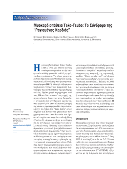
EÈÎfiÓ· 1 - Picture 1
1
AÁ·ڈÛË
1
Casting Unit
2
MË ÎˆÓÈÎfi Û¯‹Ì·
2
Non conical shapes
3
¶ÂÚÈÛÛfiÙÂÚ˜ ÂÈÊ¿ÓÂȘ ‰È·ÓÔÌ‹˜ ‰˘Ó¿ÌˆÓ
3
More distribution surfaces
4
YÔ‰Ô¯¤˜ ÂÍ¿ÁˆÓˆÓ ·ÍÈÌ·‰ÈÒÓ
4
Slots for hexagonal nuts
5
YÔ‰Ô¯‹ ÁÈ· ÛˆÏËÓ¿ÎÈ ÂÓÂÌ¿ÙˆÛ˘
5
Conection hole for grouting tubes
6
KÒÓÔ˜ ¤ÓˆÛ˘ Ì Û›ڈ̷
6
Threaded link cone
7a
™˘Ó‰ÂÛÌÔÏÔÁ›· Ù˘ÈÎÒÓ ÛˆÏ‹ÓˆÓ
7a
Coupling for standard sheaths
7b
™˘Ó‰ÂÛÌÔÏÔÁ›· ÛˆÏ‹ÓˆÓ ÌÂÁ·Ï‡ÙÂÚ˘ ‰È·Ì¤ÙÚÔ˘
7b
Coupling for larger sheaths
8-9
B›‰Â˜ Û‡Ó‰ÂÛ˘ ÛÙÔÓ Í˘ÏfiÙ˘Ô Î·È ·ÍÈÌ¿‰È·
8-9
Clamping bolts and nuts
7
master2
22/9/2006
12:48 ÌÌ
™ÂÏ›‰·8
∆¤ÓÔÓÙ˜
Cables
√È Ù¤ÓÔÓÙ˜ Â›Ó·È Î·Ù·Û΢·Ṳ̂ÓÔÈ ·fi ¯¿Ï˘‚· ˘„ËÏ‹˜ ·ÓÙÔ¯‹˜ ·ÔÙÂÏÔ‡ÌÂÓÔÈ ·fi 7-Îψӷ Û˘ÚÌ·ÙfiÛ¯ÔÈÓ· ‰È·Ì¤ÙÚÔ˘ 0,6’’ ÙˆÓ ÔÔ›ˆÓ Ù· ¯·Ú·ÎÙËÚÈÛÙÈο Ê·›ÓÔÓÙ·È ÛÙÔÓ ›Ó·Î· 1.
The cables are made up of hightensile steel 0,6’’
strands, whose characteristics are listed in Table 1.
√È Ù¤ÓÔÓÙ˜, ·ÔÙÂÏÔ‡ÓÙ·È ·fi Û˘ÁÎÂÎÚÈ̤ÓÔ Ï‹ıÔ˜ Û˘ÚÌ·ÙfiÛ¯ÔÈÓˆÓ Î·È ÂÚÈ‚¿ÏÏÔÓÙ·È ·fi ·˘Ï·ÎˆÙ‹ ۈϋӷ ·fi ¯·Ï˘‚‰fiÊ˘ÏÏÔ, ÛÙËÓ ÂÚ›ÙˆÛË ÂÛˆÙÂÚÈÎÒÓ ÙÂÓfiÓÙˆÓ ‹ ·fi ˘„ËÏ‹˜ ˘ÎÓfiÙËÙ·˜ ÔÏ˘·Èı˘ÏÂÓ›Ô˘ (HDPE) ۈϋÓ˜ ÛÙËÓ ÂÚ›ÙˆÛË Â͈ÙÂÚÈÎÒÓ ÙÂÓfiÓÙˆÓ. ∞ÏÒ˜ ·ÏÏ¿˙ÔÓÙ·˜ ÙÔ
̤ÁÂıÔ˜ ÙˆÓ Û˘ÚÌ·ÙfiÛ¯ÔÈÓˆÓ Î·È ÙÔ Ï‹ıÔ˜ ÙÔ˘˜
Â›Ó·È ‰˘Ó·ÙfiÓ Ó· ηٷÛ΢·ÛÙÔ‡Ó Ù¤ÓÔÓÙ˜ Ì ÙËÓ
ÂÈı˘ÌËÙ‹ ÈηÓfiÙËÙ· ÁÈ· ÙÔ Î¿ı ¤ÚÁÔ.
The bundle of strands is encased in a sheath of
corrugated steel strip in case of internal tendons, or
in high density polyethylene (HDPE) tubes in case
of external ones. By simply varying the strands size
and their number it is possible to produce cables of
any required capacity.
To assure a better protection of the strands from
corrosion and to insulate them electrically, it is
advisable to use a corrugated HDPE sheath instead
of the corrugated steel one.
°È· Ó· ‰È·ÛÊ·ÏÈÛÙ› ηχÙÂÚË ÚÔÛÙ·Û›· ÙˆÓ Û˘ÚÌ·ÙfiÛ¯ÔÈÓˆÓ ·fi ÙË ‰È¿‚ÚˆÛË Î·È ÁÈ· Ó· ‰È·ÛÊ·ÏÈÛı› Ë ËÏÂÎÙÚÔ¯ËÌÈ΋ ÙÔ˘˜ ÌfiÓˆÛË, ÂÓ›ÔÙ ÂӉ›ÎÓ˘Ù·È Ó· ¯ÚËÛÈÌÔÔÈÂ›Ù·È ÛˆÏ‹Ó· ·fi HDPE ·ÓÙ›
Ù˘ ¯·Ï‡‚‰ÈÓ˘.
¶›Ó·Î·˜ 1 - ∆able 1
∫·ÓÔÓÈÛÌfi˜ ¢È¿ÌÂÙÚÔ˜ √ÓÔÌ·Û›· µ¿ÚÔ˜ √ÓÔÌ·ÛÙÈ΋
∂ÈÊ¿ÓÂÈ·
Norm
Nominal
Type Weight Nominal
Diameter
area
÷ڷÎÙËÚÈÛÙÈΤ˜ ∆È̤˜
Characteristic values
£Ú·‡ÛË
Braking
Fm
mm inch
fm
™˘Ì‚·ÙÈÎfi fiÚÈÔ ∂Ï¿¯ÈÛÙÔ ÊÔÚÙ›Ô ÛÙÔ
¢È·ÚÚÔ‹˜ 0,1% 1% Ù˘ ÂÈÌ‹Î˘ÓÛ˘
[÷ÌËÏ‹ ¯·Ï¿ÚˆÛË]
Proof load
Load at 1% elongation
0,1%
[Low Relaxation]
Fp(0.1)
fp(0.1)
Fp(1)k
fp(1)k
kgr/m
mm2
kN N/mm2
kN
N/mm2
kN
N/mm2
15,2 0,6’’
Y1770S7
1,086
139
246
1770
212
1525
-
-
15,2 0,6’’
Y1860S7
1,086
139
259
1860
223
1600
-
-
15,7 0,6’’
Y1770S7
1,172
150
266
1770
229
1525
-
-
15,7 0,6’’
Y1860S7
1,172
150
279
1860
240
1600
-
-
pr EN
10138
¤Î‰.2004
8
ASTM
15,2 0,6’’ Grade250 1,094
139,4
240,2 1720
-
-
216,2
1550
A416-02
15,24 0,6’’ Grade270 1,102
140,0
260,7 1860
-
-
234,6
1680
master2
22/9/2006
12:48 ÌÌ
™ÂÏ›‰·9
Post tensioning system
∞lg a
Cable
√È Ù¤ÓÔÓÙ˜ ÌÔÚÔ‡Ó Ó· ηٷÛ΢·ÛÙÔ‡Ó ÛÙȘ ÂÁηٷÛÙ¿ÛÂȘ Ù˘ ∂§∂ª∫∞ Î·È Ó· ÛÙ·ÏÔ‡Ó ÛÙÔ ¤ÚÁÔ ‹
Ó· ηٷÛ΢·ÛÙÔ‡Ó Â› ÙfiÔ˘ ÛÙÔ ÂÚÁÔÙ¿ÍÈÔ, Ô˘
Â›Ó·È Î·È ÙÔ ÈÔ Û‡ÓËı˜.
The cables can be produced at ELEMKA workshop
and sent to the construction site, or can be
manufactured in-situ, that is the most common
practice.
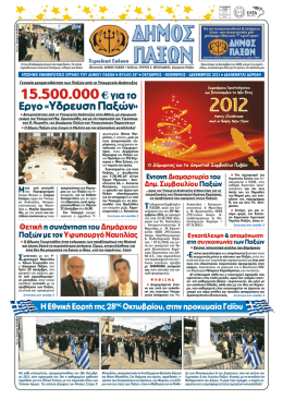
™ÙËÓ ÂÚ›ÙˆÛË Ù˘ › ÙfiÔ˘ ηٷÛ΢‹˜ Ù· Û˘ÚÌ·ÙfiÛ¯ÔÈÓ· ÚÔˆıÔ‡ÓÙ·È ÛÙÔÓ ÛˆÏ‹Ó· (∂ÈÎfiÓ·
2·) Ì ÂȉÈΤ˜ ÚÔˆıËÙÈΤ˜ Ì˯·Ó¤˜ ÚÈÓ ‹ ÌÂÙ¿ ÙË
Û΢ÚÔ‰¤ÙËÛË, ·Ó¿ÏÔÁ· Ì ÙȘ ηٷÛ΢·ÛÙÈΤ˜ ··ÈÙ‹ÛÂȘ. ∂›Ó·È ›Û˘ ‰˘Ó·Ùfi Ó· Á›ÓÂÈ ÙÔÔı¤ÙËÛË
ÙˆÓ Û˘ÚÌ·ÙfiÛ¯ÔÈÓˆÓ Ì ÂȉÈΤ˜ “οÏÙÛ˜” Î·È ‚·ÚÔ‡Ïη (∂ÈÎfiÓ· 2‚).
At the case of in-situ construction the strands are
threaded inside the duct (Picture 2a) with special
pushing machines before or after concreting,
according to the construction needs. It is also
possible to install the strands by pulling with
special sockets and a winch (Picture 2b).
∆Ô ÂÚ›‚ÏËÌ· ÙˆÓ ÙÂÓfiÓÙˆÓ Î·Ù·Û΢¿˙ÂÙ·È ÛÙȘ ÂÁηٷÛÙ¿ÛÂȘ Ì·˜ ÛÙË £ÂÛÛ·ÏÔÓ›ÎË (¯·Ï˘‚‰fiÊ˘ÏÏÔ 0,30 ~ 0,60 mm, Á·Ï‚·ÓÈṲ̂ÓÔ ‹ ·Ïfi) ηχÙÔÓÙ·˜ fiÏÔ ÙÔ Â‡ÚÔ˜ ÙˆÓ ··ÈÙ‹ÛˆÓ. ∆Ô ¯·Ï˘‚‰fiÊ˘ÏÏÔ Ô˘ ¯ÚËÛÈÌÔÔÈÂ›Ù·È ÁÈ· ÙËÓ ·Ú·ÁˆÁ‹
Ù˘ ۈϋӷ˜ ¤¯ÂÈ ÙÔ ¿¯Ô˜ Ô˘ ··ÈÙÂ›Ù·È ·fi ÙÔ
EN 523.
¶ÚÔˆıËÙÈ΋ Ì˯·Ó‹
Pussing machine
The sheath is manufactured at ELEMKA storehouse
at Thessalonica (steel strip 0,30~0,60mm,
galvanized or simple) covering the whole range.
The steel strip gauge that is used to manufacture
the sheath is in accordance with EN 523.
∞Ó¤ÌË
Decoiler
™ˆÏ‹Ó· ÚÔÛÙ·Û›·˜
Protective tube
EÈÎfiÓ· 2· - Picture 2a
™˘ÚÌ·ÙfiÛ¯ÔÈÓ·
Strands
µ·ÚÔ‡ÏÎÔ
Winch
K¿ÏÙÛ· ‹ ËÏÂÎÙÚÔÎfiÏÏËÛË
Socket or welding
EÈÎfiÓ· 2‚ - Picture 2b
9
master2
22/9/2006
12:48 ÌÌ
™ÂÏ›‰·10
∆ÔÔı¤ÙËÛË ÙˆÓ ÙÂÓfiÓÙˆÓ
Installation of cables
√È ·Á΢ÚÒÛÂȘ ÙÔÔıÂÙÔ‡ÓÙ·È ÛÙÔÓ Í˘ÏfiÙ˘Ô Ì ‚›‰Â˜ Î·È ·ÍÈÌ¿‰È· (∂ÈÎfiÓ· 1, ÙÂÌ. 8-9) Î·È Â¿Ó Á›ÓÂÈ
ÛˆÛÙ‹ ¿ÏÂÈ„Ë Ì Ͽ‰È, Ô Í˘ÏfiÙ˘Ô˜ ·ÔÌ·ÎÚ‡ÓÂÙ·È Ôχ ‡ÎÔÏ· ÌÂÙ¿ ÙË Û΢ÚÔ‰¤ÙËÛË. ŸÏ˜ ÔÈ ÂÓÒÛÂȘ ÙˆÓ ÙÂÓfiÓÙˆÓ Ú¤ÂÈ Ó· ·ÛÊ·Ï›˙ÔÓÙ·È Ôχ
ÚÔÛ¯ÙÈο Ì ٷÈÓ›· ‹ ÂȉÈο ıÂÚÌÔÏ·ÛÙÈο ˘ÏÈο.
The anchorages are fixed to the formwork by nuts
and screws (Picture 1, pos. 8-9); which, when
properly greased, can be easily removed after
concreting. All connections along the cable must
be carefully sealed with adhesive tape or heat
shrinking sleeves.
∏ ÙÔÔı¤ÙËÛË ÙˆÓ ÙÂÓfiÓÙˆÓ Á›ÓÂÙ·È Ù·˘Ùfi¯ÚÔÓ· ÌÂ
ÙËÓ ÙÔÔı¤ÙËÛË ÙÔ˘ ¯·Ï·ÚÔ‡ ÔÏÈÛÌÔ‡ Î·È ÁÈ· ÙÔ
ÏfiÁÔ ·˘Ùfi ı· Ú¤ÂÈ Ó· Á›ÓÂÙ·È Î·Ï‹ Û˘ÓÂÓÓfiËÛË
ÙˆÓ Û˘ÓÂÚÁ›ˆÓ ÒÛÙ ӷ ·ÔʇÁÔÓÙ·È Î·ı˘ÛÙÂÚ‹ÛÂȘ Î·È Î·ÎÔÙ¯ӛ˜.
The installation of the cables is done at the same
time that the installation of reinforcement occurs.
Due to this reason it should be noticed that, with
good cooperation between the teams we can avoid
any delay or any construction defects in the structure.
∆ÔÔıÂÙÂ›Ù·È ÙÌ‹Ì· ÙÔ˘ ¯·Ï·ÚÔ‡ ÔÏÈÛÌÔ‡ Î·È ·ÎÔÏÔ˘ı› Ë ÙÔÔı¤ÙËÛË ÙˆÓ ÛˆÏ‹ÓˆÓ ÚÔ¤ÓÙ·Û˘
ÛÙ· ÂӉ‰ÂÈÁ̤ӷ ÛËÌ›· ·fi ÙËÓ ÌÂϤÙË. ∆ÔÔıÂÙÔ‡ÓÙ·È ÛÙËÚ›ÁÌ·Ù· ·fi ÔÏÈÛÌfi O
/ 12 ·Ó¿ 1m Ù· ÔÔ›· ‰¤ÓÔÓÙ·È Ì ۇÚÌ· ÛÙÔÓ ˘¿Ú¯ÔÓ ¯·Ï·Úfi ÔÏÈÛÌfi.
Part of the reinforcement is installed and
the installation of sheath follows at the support
points that are given to the design drawings.
The supports should be O
/ 12 reinforcement, at a
distance of 1m between them, which are tied with
tie-wire at the existing reinforcement.
∆ÔÔı¤ÙËÛË ÙˆÓ ÙÂÓfiÓÙˆÓ ÛÙË ıÂÌÂÏ›ˆÛË Ù˘ Á¤Ê˘Ú·˜ ÙÔ˘ Wadi Leban
Tendon installation at the foundation of Wadi Leban bridge
10
master2
22/9/2006
12:48 ÌÌ
™ÂÏ›‰·11
™‡ÛÙËÌ· ÚÔ¤ÓÙ·Û˘
∞lg a
Cable
∂¿Ó Ù· Û˘ÚÌ·ÙfiÛ¯ÔÈÓ· ı· ÙÔÔıÂÙËıÔ‡Ó ÌÂÙ¿ ÙË Û΢ÚÔ‰¤ÙËÛË Ù· ÛÙËÚ›ÁÌ·Ù· ·˘Ù¿ ı· Ú¤ÂÈ Ó· Â›Ó·È ÙÔ˘Ï¿¯ÈÛÙÔÓ ·Ó¿ 0,5m.
If the strands are going to be
threaded after concreting these
supports should be installed with a
spacing of at least 0,5m.
™·Ó ηÓfiÓ·˜ ı· Ú¤ÂÈ Ë ÂÈÎ¿Ï˘„Ë ÙˆÓ
ÛˆÏ‹ÓˆÓ Ó· Â›Ó·È ÙÔ˘Ï¿¯ÈÛÙÔÓ ›ÛË ÚÔ˜
ÙË ‰È¿ÌÂÙÚfi ÙÔ˘˜ Î·È Û η̛· ÂÚ›ÙˆÛË ÌÈÎÚfiÙÂÚË ÙˆÓ 40~50mm (∂ÈÎfiÓ· 3).
As a rule the concrete cover of the
sheath should be at least equal to
their diameter and it should be not
less than 40~50mm (Picture 3).
ŸÙ·Ó Ï‹ıÔ˜ ÙÂÓfiÓÙˆÓ ‚Ú›ÛÎÂÙ·È Û˘ÁÎÂÓÙڈ̤ÓÔ Û ¤Ó· ÛËÌÂ›Ô ı· Ú¤ÂÈ
Ó· Ï·Ì‚¿ÓÂÙ·È Ì¤ÚÈÌÓ· ÒÛÙ ӷ ÌÔÚ› Ó· Á›ÓÂÈ Ë ¤Á¯˘ÛË ÙÔ˘ Û΢ÚÔ‰¤Ì·ÙÔ˜ Î·È Ë ÛˆÛÙ‹ ‰fiÓËÛ‹ ÙÔ˘, ÁÈ·Ù› ÛÂ
ÂÚÈÙÒÛÂȘ Ô˘ ‰ÂÓ ˘¿Ú¯ÂÈ ¯ÒÚÔ˜
Ó· ÂÚ¿ÛÂÈ Ô ‰ÔÓËÙ‹˜, ‰ËÌÈÔ˘ÚÁÔ‡ÓÙ·È ˙ËÌȤ˜ ÛÙÔ˘˜ Ù¤ÓÔÓÙ˜ (ÂÈÛÚÔ‹
Û΢ÚÔ‰¤Ì·ÙÔ˜) ‹ ‰ÂÓ ÂÈÙ˘Á¯¿ÓÂÙ·È
ÛˆÛÙ‹ Û˘Ì‡ÎÓˆÛË.
>O
/
d > 40
{
/
h >O
> 50
{
/
k >O
EÈÎfiÓ· 3 - Picture 3
When many tendons are present in a
section, it is necessary to provide
spaces to pour the concrete and to
vibrate correctly since in case of not
enough space, the tendons will be
harmed (concrete will enter inside
the duct) or the compaction of
concrete will be insufficient.
°¤Ê˘Ú˜ ÛÙËÓ ∂ÁÓ·Ù›· √‰fi
Bridges at Egnatia Road
11
master2
22/9/2006
12:48 ÌÌ
™ÂÏ›‰·12
™˘ÚÌ·ÙfiÛ¯ÔÈÓ·
Strands
∆· Û˘ÚÌ·ÙfiÛ¯ÔÈÓ· Â›Ó·È Î·Ù·Û΢·Ṳ̂ӷ ·fi 7
ÎÏÒÓÔ˘˜: 1 ÎÂÓÙÚÈÎfi˜ ¢ı‡ÁÚ·ÌÌÔ˜ ÎÏÒÓÔ˜ Á‡Úˆ
·fi ÙÔÓ ÔÔ›Ô Â›Ó·È ÏÂÁ̤ÓÔÈ 6 ÎÏÒÓÔÈ Û ÂÏÈÎÔÂȉ‹ ÌÔÚÊ‹.
The strands are formed with seven steel wires: one
central wire around which the other six are
wrapped.
∆· Û˘ÚÌ·ÙfiÛ¯ÔÈÓ· ·Ú·Û΢¿˙ÔÓÙ·È Ì ÙË Ì¤ıÔ‰Ô
ÙÔ˘ ¯·ÌËÏÔ‡ ‚·ıÌÔ‡ ¯·Ï¿ÚˆÛ˘, Î·È Â›Ó·È ÈÛÙÔÔÈË̤ӷ ·fi ·ÓÂÍ¿ÚÙËÙ· ÂÚÁ·ÛÙ‹ÚÈ·. ¶ÚÔÌËı‡ÔÓÙ·È Û ÎÔ˘ÏÔ‡Ú˜ Ì ÙȘ ηو٤ڈ ‰È·ÛÙ¿ÛÂȘ:
The strands are generally supplied already
stabilized (low relaxation) and certified according
to the regulations by an independent laboratory.
They are supplied in coils with the following
dimensions
∂͈ÙÂÚÈ΋ ¢È¿ÌÂÙÚÔ˜:
1200~1500mm
Outer Diameter:
1200~1500mm
∂ÛˆÙÂÚÈ΋ ¢È¿ÌÂÙÚÔ˜:
700~800mm
Inner Diameter:
700~800mm
¶Ï¿ÙÔ˜:
700~750mm
Width:
700~750mm
µ¿ÚÔ˜:
3000~4000kgr
Weight:
3000~4000kgr
∆· ¯·Ú·ÎÙËÚÈÛÙÈο ÙˆÓ Û˘Ì‚·ÙÒÓ ¯·Ï‡‚ˆÓ, Ê·›ÓÔÓÙ·È ÛÙÔÓ ¶›Ó·Î· 1 (ÛÂÏ. 8).
The strand properties are shown on Table 1 (page 8).
∏ ∂§∂ª∫∞ ∞.∂. ÂÈÛ¿ÁÂÈ ÛÙËÓ ∂ÏÏ¿‰· ¯¿Ï˘‚· ÚÔ¤ÓÙ·Û˘ ·fi ÙÔ˘˜ ÌÂÁ·Ï‡ÙÂÚÔ˘˜ ÚÔÌËıÂ˘Ù¤˜ Ù˘
∂˘ÚÒ˘ ÒÛÙ ӷ ÂÍ·ÛÊ·Ï›˙ÂÙ·È Ë Î·Ï‡ÙÂÚË ÔÈfiÙËÙ· Î·È Ô ¿ÌÂÛÔ˜ ¯ÚfiÓÔ˜ ·Ú¿‰ÔÛ˘.
ELEMKA S.A. imports in Greece PC strand from the
biggest factories of Europe having the best
delivery time and the best quality.
ŸÙ·Ó ··ÈÙÔ‡ÓÙ·È Ù¤ÓÔÓÙ˜ Â͈ÙÂÚÈ΋˜ ÚÔ¤ÓÙ·Û˘
ÌÔÚ› Ó· ¯ÚËÛÈÌÔÔÈËı› ¯¿Ï˘‚·˜ Ì ÂÈÎ¿Ï˘„Ë
ÁÚ¿ÛÔ˘ ‹ ÂÈÎÂڈ̤ÓÔ˜ Û ۈϋӷ ·fi HDPE, Ô ÔÔ›Ô˜ ‰ÂÓ ¤¯ÂÈ Û˘Ó¿ÊÂÈ· Ì ÙÔÓ ÊÔÚ¤· (unbonded).
∆· Û˘ÚÌ·ÙfiÛ¯ÔÈÓ· ·˘Ù¿ ÌÔÚ› Ó· Â›Ó·È Î·È Á·Ï‚·ÓÈṲ̂ӷ, Ì ‰È·ÊÔÚÂÙÈο fï˜ Ì˯·ÓÈο ¯·Ú·ÎÙËÚÈÛÙÈο (ÌÈÎÚfiÙÂÚ· fiÚÈ· ‰È·ÚÚÔ‹˜ Î·È ıÚ·‡Û˘).
* °È· Ù¤ÓÔÓÙ˜ ÔÈ ÔÔ›ÔÈ ı· ÙÔÔıÂÙËıÔ‡Ó Ù· Û˘ÚÌ·ÙfiÛ¯ÔÈÓ· ÌÂÙ¿ ÙË Û΢ÚÔ‰¤ÙËÛË ı· Ú¤ÂÈ Ó·
¯ÚËÛÈÌÔÔÈËı› ۈϋӷ ·fi ·¯‡ÙÂÚÔ ÙÛ¤ÚÎÈ Î·Ù¿
0,05mm Î·È Ì ÌÂÁ·Ï‡ÙÂÚË ‰È¿ÌÂÙÚÔ Î·Ù¿ 10mm.
12
When it is requested to provide tendons for
external prestressing, greased or waxed strand can
be used in HDPE duct, commonly called
unbonded. Such strands can be hot galvanized too
but the mechanical characteristics will be different
( lower yield and breaking values).
* For cables that are going to be threaded after
concreting the steel strip will have to be thicker by
0,05mm and the diameter 10mm above the typical.
master2
22/9/2006
12:48 ÌÌ
™ÂÏ›‰·13
Post tensioning system
∞lg a
Cable
™ˆÏ‹Ó˜ Î·È ™‡Ó‰ÂÛÌÔÈ - Sheaths and Couplings
E¿Ó ··ÈÙ›ٷÈ
If necessary
3
1
1
2
3
4∆15
™ˆÏ‹Ó·
45/51
Sheath
O
/ iO
/e
™‡Ó‰ÂÛÌÔ˜
50/56
Coupling
O
/ iO
/e
∆ËÏÂÛÎÔÈ΋ ۈϋӷ
55/61
Telescopic duct
O
/ iO
/e
∫·Ì˘ÏfiÙËÙ·
3500
Radius
Rmin
∂˘ı‡ÁÚ·ÌÌÔ ÙÌ‹Ì·
500
Straight line
G min
2
7∆15
12∆15
15∆15
19∆15
22∆15
27∆15
31∆15
55/61
75/81
80/86
90/96
60/66
80/86
85/91
95/101 105/111 115/121 120/126
65/71
85/91
90/96
100/106 110/116 120/126 125/131
4500
6000
6500
7500
8000
9000
10000
600
700
900
1000
1100
1200
1300
100/106 110/116 115/121
ŸÏ˜ ÔÈ ‰È·ÛÙ¿ÛÂȘ Â›Ó·È Û mm - All dimensions in mm
√ÏÈÛÌfi˜ ªÂÙÒÔ˘ ∞Á·ڈÛ˘
¶ÚÔÒıËÛË Û˘ÚÌ·ÙfiÛ¯ÔÈÓˆÓ
End Block Reinforcement
Threading of strands
13
master2
22/9/2006
12:48 ÌÌ
™ÂÏ›‰·14
∞Á΢ÚÒÛÂȘ
Anchorages
√È ÂÓÂÚÁ¤˜ ·Á΢ÚÒÛÂȘ Ù‡Ô˘ “M” - ∂ÈÎfiÓ· 4 - ›ӷÈ
ηٷÛ΢·Ṳ̂Ó˜ ·fi Ì›· ¯·Ï‡‚‰ÈÓË ÎÂÊ·Ï‹, ¿Óˆ ÛÙËÓ ÔÔ›· Ù· Û˘ÚÌ·ÙfiÛ¯ÔÈÓ· ·ÛÊ·Ï›˙ÔÓÙ·È ÌÂÌÔӈ̤ӷ Ì ÂȉÈΤ˜ ÛÊ‹Ó˜, Î·È ·fi Ì›· ÛÊ·ÈÚÔÂȉ‹ ÂÁÎÈ‚ˆÙÈ˙fiÌÂÓË ÌÔÓ¿‰·.
Mechanical Stressing Anchorages type “M” Picture 4 - are formed by a steel anchor head, on
which the strands are individually gripped by
specific wedges, and by spheroidal casting unit.
√È ¿ÁȘ ·Á΢ÚÒÛÂȘ ÌÔÚ› Ó· Â›Ó·È ÙˆÓ Ù‡ˆÓ
“B”, “S”, “F” Î·È “E” ‹ “M” ›Û˘, Â¿Ó ·˘Ù‹ ÌÔÚ› Ó·
Â›Ó·È ÚÔÛ‚¿ÛÈÌË. √È Û˘Ó‰¤ÛÂȘ ÙˆÓ ÙÂÓfiÓÙˆÓ Á›ÓÂÙ·È Ì Ì˯·ÓÈÎÔ‡˜ Û˘Ó‰¤ÛÌÔ˘˜ Ù‡Ô˘ “K” -ÛÙ·ıÂÚÒÓ ‹ Ù‡Ô˘ “V” - ÎÈÓËÙÒÓ.
À¿Ú¯ÂÈ Â›Û˘ Ô Ù‡Ô˜ “G” Ô˘ Â›Ó·È ÎÈÓËÙ‹ ÎÂÊ·Ï‹, Ë ÔÔ›· ¯ÚËÛÈÌÔÔÈÂ›Ù·È fiÙ·Ó ‰ÂÓ ÂÈÙÚ¤ÂÈ Ô
¯ÒÚÔ˜ ÙË ¯Ú‹ÛË Ù˘ “V”.
À¿Ú¯Ô˘Ó Ù¤ÏÔ˜ Î·È ·Á΢ÚÒÛÂȘ Ù‡Ô˘ “C”, Ô˘
¯ÚËÛÈÌÔÔÈÔ‡ÓÙ·È Û·Ó ÂӉȿÌÂÛ˜ ·Á΢ÚÒÛÂȘ, ÁÈ·
ÙËÓ Ù¿Ó˘ÛË ·fi ¤Ó· ÂӉȿÌÂÛÔ ÛËÌ›Ô, ·ÓÙ› ·fi Ù·
¿ÎÚ·. ∂›Ó·È ȉ·ÓÈΤ˜ ÁÈ· ÙËÓ Ù¿Ó˘ÛË ‰·ÎÙ˘ÏÈÔÂȉÒÓ
ÙÂÓfiÓÙˆÓ ¯ˆÚ›˜ ‰È·ÊÚ¿ÁÌ·Ù·.
°È· Ó· ‰ËÌÈÔ˘ÚÁËıÔ‡Ó Ù¤ÓÔÓÙ˜ Ì ·ÚÈıÌfi Û˘ÚÌ·ÙfiÛ¯ÔÈÓˆÓ ÌÂÁ·Ï‡ÙÂÚÔ ·fi ÙÔ Ù˘ÈÎfi, ·ÚΛ Ó· ÂÈϤÍÔ˘Ì ÙËÓ ·Á·ڈÛË Ì ÙËÓ ÌÂÁ·Ï‡ÙÂÚË ÈηÓfiÙËÙ· (.¯.
ÁÈ· Ù¤ÓÔÓÙ· 13∆15 ı· ÂÈϤÍÔ˘Ì ·Á·ڈÛË 15∆15).
ŸÏ· Ù· ¯·Ú·ÎÙËÚÈÛÙÈο Ô˘ ‰›ÓÔÓÙ·È ÛÙȘ Ù¯ÓÈΤ˜
ηÚ٤Ϙ Â›Ó·È Û¯ÂÙÈο Ì ÙË Ì¤ÁÈÛÙË ‰˘Ó·ÙfiÙËÙ· 1
Û˘ÚÌ·ÙfiÛ¯ÔÈÓÔ˘, 0,6’’ (279kN) Ô˘ ·ÓÙÈÛÙÔȯ› ÛÂ
¯¿Ï˘‚· SUPER (150mm2) 1860.
Fixed anchorages can be “B”, “S”, “F” and “E” or “M”
too, if it is accessible. Coupling of the tendons can
be done with mechanical type “K” -fixed or
movable “V”.
Also, type “G” can be supplied, as a movable
coupler, when the space required is less than the
one required by type “V”.
Anchorage type “C”, is used as an intermediate
stressing head to allow tensioning of the tendons
through an intermediate point rather than from
the ends: they are essential for the tensioning of
ring cables without bulk-heads.
To produce tendons with a number of strand
different than the typical one, it is necessary to use
the next anchorage of upper capacity (ie. For cable
13∆15 we will chose anchorage 15∆15).
All the data given to the technical cards are relative
to the use of the higher capacity of 1 strand, 0,6’’
(279kN) SUPER (150mm2) 1860.
∞Á΢ÚÒÛÂȘ Ù‡Ô˘ “∂”
Anchorages, type “E”
14
master2
22/9/2006
12:48 ÌÌ
™ÂÏ›‰·15
™‡ÛÙËÌ· ÚÔ¤ÓÙ·Û˘
M
K
B
S
∞lg a
Cable
EÈÎfiÓ· 4 - Picture 4
√ÏÈÛÌfi˜ ÙÔ˘ ÌÂÙÒÔ˘ ·Á·ڈÛ˘
End block reinforcement
∏ Ù¯ÓÈ΋ ηÚ٤Ϸ Ù˘ ·Á·ڈÛ˘ “M” ‰›ÓÂÈ ÙȘ ¯·Ú·ÎÙËÚÈÛÙÈΤ˜ ·ÔÛÙ¿ÛÂȘ “X” ÙˆÓ ·Á΢ÚÒÛÂˆÓ M,F,E
Î·È K ÁÈ· 3 Ù˘ÈΤ˜ ÎÏ¿ÛÂȘ Û΢ÚÔ‰¤Ì·ÙÔ˜, Û‡Ìʈӷ
Ì ÙËÓ ·ÓÙÔ¯‹ ΢ÏÈÓ‰ÚÈÎÔ‡ ‰ÔÎÈÌ›Ô˘ 28ËÌÂÚÒÓ.
The technical card of “M” anchorage gives the
characteristic anchorage spacing “X” of type M,F,E
and K for 3 typical concrete classes, according to
their cylindrical characteristic strength at 28 days.
∏ ·fiÛÙ·ÛË ÌÂٷ͇ ÙˆÓ ·Á΢ÚÒÛÂˆÓ X*X=X2 ÌÔÚ› Ó· ÌÂÙ·‚ÏËı› Û 0,8Ã*1,25Ã=Ã2. ∏ ÌÈÎÚfiÙÂÚË ·fiÛÙ·ÛË ÙÔ˘ ΤÓÙÚÔ˘ Ì›·˜ ·Á·ڈÛ˘ ·fi ÙËÓ ¿ÎÚË
ÙÔ˘ ÌÂÙÒÔ˘ ı· Ú¤ÂÈ Ó· Â›Ó·È ÙÔ˘Ï¿¯ÈÛÙÔÓ > Ã/2
+10mm Â¿Ó ‰ÂÓ ··ÈÙÂ›Ù·È ÌÂÁ·Ï‡ÙÂÚË ÂÈÎ¿Ï˘„Ë.
The anchorage spacing X*X=X2 can be modified to
0,8Ã*1,25Ã=Ã2. The minimum clearance of an
anchorage to the edge must be > Ã/2 +10mm, if a
higher cover is not required.
°È· Û΢ÚÔ‰¤Ì·Ù· ÂӉȿÌÂÛ˘ ÎÏ¿Û˘ ÙˆÓ ·Ó·ÊÂÚfiÌÂÓˆÓ, Ù· ‰Â‰Ô̤ӷ ÌÔÚÔ‡Ó Ó· ÂÍ·¯ıÔ‡Ó ÌÂ
·ÚÂÌ‚ÔÏ‹.
∏ ̤ÁÈÛÙË ‰‡Ó·ÌË ÚÔ¤ÓÙ·Û˘ F0 ÛÙËÓ ·Á·ڈÛË,
80% ÙÔ˘ ÔÚ›Ô˘ ıÚ·‡Û˘ ÙÔ˘ Ù¤ÓÔÓÙ· ı· ÌÔÚ› Ó· ÂÊ·ÚÌÔÛı› fiÙ·Ó ÙÔ Û΢Úfi‰ÂÌ· ı· ¤¯ÂÈ ÙÔ˘Ï¿¯ÈÛÙÔÓ
ÙËÓ Ì¤ÛË ·ÓÙÔ¯‹ fcm.0 fiˆ˜ Ê·›ÓÂÙ·È ÛÙÔ˘˜ ›Ó·Î˜.
∏ ‰‡Ó·ÌË 0.5 F0 ÌÔÚ› Ó· ÂÊ·ÚÌÔÛı› fiÙ·Ó ÙÔ Û΢Úfi‰ÂÌ· ¤¯ÂÈ ·ÓÙÔ¯‹ > 0.65 fcm.0. °È· ÂӉȿÌÂÛ˜ ‰˘Ó¿ÌÂȘ, Ù·
‰Â‰Ô̤ӷ ÌÔÚÔ‡Ó Ó· ÂÍ·¯ıÔ‡Ó Ì ·ÚÂÌ‚ÔÏ‹.
2
√È Û›Ú˜ (fiÚÈÔ ‰È·ÚÚÔ‹˜ > 420 N/mm ) Ô˘ Ê·›ÓÔÓÙ·È ÛÙÔ˘˜ ›Ó·Î˜ ÌÔÚÔ‡Ó Ó· ·ÓÙÈηٷÛÙ·ıÔ‡Ó
·fi ·ÓÙ›ÛÙÔÈ¯Ô ÔÚıÔÁÒÓÈÔ ÔÏÈÛÌfi.
For concrete of intermediate strength the data in
the chart can be interpolated.
The maximum force F0 at the anchorage, 80% of
nominal breaking load, may be applied when the
concrete will have at least the average strength
fcm.0 shown in the charts.
The force 0.5 F0 can be applied when the concrete
has reached a strength > 0.65 fcm.0.
For intermediate forces the data can be
interpolated.
The spirals (yield strength > 420 N/mm2) that are
shown in the data sheets may be replaced by an
equivalent orthogonal reinforcement.
15
master2
22/9/2006
12:48 ÌÌ
™ÂÏ›‰·16
EÓÂÚÁ‹ ∞Á·ڈÛË - Stressing Anchorage
1
M
4
*
5
2
3
¢È¿Ù·ÍË - Spacing
6
M¤ÁÂıÔ˜ ∆¤ÓÔÓÙ· - ∆endon size
™ÒÌ· ·Á·ڈÛ˘
Casting Unit
T
L
Z
U
2
A
∫ÂÊ·Ï‹ ·Á·ڈÛ˘
H
Anchor head
3
J
∫ÒÓÔ˜ - Cone
n
™ÙÚÔʤ˜ - Turns
4
D
™Â›Ú· - Spiral
O
/
5
O
/i
¶ÂÚ›‚ÏËÌ· - Sheath
N
∂ÛÔ¯‹ - Recess
6
R
l/m
* ŒÓÂÌ· - Grout
M¤ÁÈÛÙË ¢‡Ó·ÌË Fo / Force max Fo [kN]
X
fcm,0
fck
25
26
[mm]
30
30
[N/mm2]
[N/mm2]
(3)
35
33
(1)
(2)
1
EÁÎÔ‹ - Slot
4∆15
O
/ 140
130
120
M10
O
/ 100
45
65
5
O
/ 170
O
/ 10
O
/ 45
180
100
1,1
893
220
205
195
7∆15
O
/ 180
160
158
M10
O
/ 125
45
65
6
O
/ 220
O
/ 12
O
/ 55
220
100
1,5
1562
280
270
260
12T15
O
/ 225
190
198
M12
O
/ 170
55
180
7
O
/ 270
O
/ 14
O
/ 75
270
110
2,8
2678
380
355
340
15T15
O
/ 255
200
225
M12
O
/ 190
60
210
7
O
/ 310
O
/ 16
O
/ 80
300
110
3,0
3348
425
400
380
19∆15
O
/ 280
220
240
M12
O
/ 200
70
225
7
O
/ 330
O
/ 18
O
/ 90
320
120
3,8
4241
475
445
425
22∆15
O
/ 310
240
265
M12
O
/ 230
75
275
8
O
/ 360
O
/ 18
O
/ 100
350
130
4,8
4910
515
480
460
1. fck= ΢ÏÈÓ‰ÚÈ΋ ¯·Ú·ÎÙËÚÈÛÙÈ΋ ·ÓÙÔ¯‹ ÛÙȘ 28 Ë̤Ú˜ - cylindrical characteristic strength at 28 days
2. fcm,0= ª¤ÛË ·ÓÙÔ¯‹ Û΢ÚÔ‰¤Ì·ÙÔ˜ ηٿ ÙËÓ Ù¿Ó˘ÛË - average concrete strength at stressing time
3. X= ·fiÛÙ·ÛË ‰È¿Ù·Í˘ ·Á΢ÚÒÛÂˆÓ - anchorage spacing
ŸÏ˜ ÔÈ ‰È·ÛÙ¿ÛÂȘ Â›Ó·È Û mm - All dimensions in mm
16
27∆15
O
/ 340
280
290
M14
O
/ 250
85
275
8
O
/ 390
O
/ 20
O
/ 110
380
140
5,8
6026
570
535
505
31∆15
O
/ 360
320
310
M14
O
/ 260
95
275
9
O
/ 410
O
/ 20
O
/ 115
400
150
6,1
6919
615
575
545
master2
22/9/2006
12:48 ÌÌ
™ÂÏ›‰·17
Post tensioning system
∞lg a
Cable
¶¿ÁȘ ∞Á΢ÚÒÛÂȘ - Fixed Anchorages
1
5
B
*
3
4a
4b
4b
2
*
4
ªfiÓÔ ÁÈ· 15∆15
Only for 19T15
4
4a
S
5
I‰¤ ÛËÌ›ˆÛË - See note
3
1
M¤ÁÂıÔ˜ ∆¤ÓÔÓÙ· - ∆endon size
AÁ·ڈÛË ∆‡Ô˘ µ
Anchorage type B
2
AÁ·ڈÛË ∆‡Ô˘ S
Anchorage type S
3
™ÙÚÔʤ˜ - Turns
™Â›Ú· - Spiral
4
TÛ¤ÚÎÈ - Stirrups
5
¶ÂÚ›‚ÏËÌ· - Sheath
L2
L1
X
Y
L
X
Y
n
D
O
/
n
P
O
/i
4∆15
900
190
210
400
160
160
4
O
/ 160
O
/8
6
50
O
/ 45
7∆15
850
1000
250
270
800
160
320
4
O
/ 170
O
/ 10
6
50
O
/ 55
12T15
950
1100
280
420
800
240
320
6
O
/ 190
O
/ 12
8
50
O
/ 75
15T15
950
1100
380
390
900
320
320
6
O
/ 190
O
/ 14
8
50
O
/ 80
19∆15
1050
1200
380
490
1100
320
400
6
O
/ 200
O
/ 16
8
60
O
/ 90
22∆15
1150
1300
470
470
27∆15
1250
1400
560
470
31∆15
1350
1500
510
570
7
O
/ 210
O
/ 16
7
O
/ 220
O
/ 16
7
O
/ 230
O
/ 18
O
/ 100
O
/ 110
O
/ 115
™ËÌ›ˆÛË: ∆Ô Ì‹ÎÔ˜ ÙÔ˘ Û˘ÚÌ·ÙfiÛ¯ÔÈÓÔ˘ Ô˘ ‰ÂÓ ¤¯ÂÈ Û˘Ó¿ÊÂÈ· Ì ÙÔ Û΢Úfi‰ÂÌ· Â›Ó·È L+200mm.
The unbonded strand length is L+200mm
*. ∏ ÔÛfiÙËÙ· ÂӤ̷ÙÔ˜ Â›Ó·È ›‰È· Ì’ ·˘Ù‹ Ô˘ Ê·›ÓÂÙ·È ÛÙËÓ ∆¯ÓÈ΋ ηÚ٤Ϸ Ù˘ ·Á·ڈÛ˘ M.
The grout quantity is shown in the technical card of M anchorage
ŸÏ˜ ÔÈ ‰È·ÛÙ¿ÛÂȘ Â›Ó·È Û mm - All dimensions in mm
17
master2
22/9/2006
12:48 ÌÌ
™ÂÏ›‰·18
¶¿ÁȘ ∞Á΢ÚÒÛÂȘ - Fixed Anchorages
1
F
4
*
5
2
3
1
E
4
*
5
2
3
1
2
3
4
5
6
M¤ÁÂıÔ˜ ∆¤ÓÔÓÙ· - ∆endon size
™ÒÌ· AÁ·ڈÛ˘
Casting Unit
KÂÊ·Ï‹ AÁ·ڈÛ˘
Anchor head
∫ÒÓÔ˜ - Cone
™ÙÚÔʤ˜ - Turns
™Â›Ú· - Spiral
¶ÂÚ›‚ÏËÌ· - Sheath
∂ÈÎ¿Ï˘„Ë - Covering
T
L
A
HF
HE
J
n
D
O
/
O
/i
RF
RE
4∆15
O
/ 140
130
O
/ 100
80
45
65
5
O
/ 170
O
/ 10
O
/ 45
130
170
7∆15
O
/ 180
160
O
/ 125
80
45
65
6
O
/ 220
O
/ 12
O
/ 55
130
170
12T15
O
/ 225
190
O
/ 170
80
55
180
7
O
/ 270
O
/ 14
O
/ 75
130
180
15T15
O
/ 255
200
O
/ 190
80
60
210
7
O
/ 310
O
/ 16
O
/ 80
130
190
19∆15
O
/ 280
220
O
/ 200
90
65
225
7
O
/ 330
O
/ 18
O
/ 90
140
190
°È· ÙËÓ ·fiÛÙ·ÛË Ù˘ ‰È¿Ù·Í˘ ÙˆÓ ·Á΢ÚÒÛÂˆÓ ÈÛ¯‡ÂÈ fiÙÈ Î·È ÁÈ· ÙȘ M
For the anchorage spacing see technical card of M anchorage
*. ∏ ÔÛfiÙËÙ· ÂӤ̷ÙÔ˜ Â›Ó·È ›‰È· Ì’ ·˘Ù‹ Ô˘ Ê·›ÓÂÙ·È ÛÙËÓ ∆¯ÓÈ΋ ηÚ٤Ϸ Ù˘ ·Á·ڈÛ˘ M.
The grout quantity is shown in the technical card of M anchorage
ŸÏ˜ ÔÈ ‰È·ÛÙ¿ÛÂȘ Â›Ó·È Û mm - All dimensions in mm
18
22∆15
O
/ 310
240
O
/ 230
95
70
275
8
O
/ 360
O
/ 18
O
/ 100
140
200
27∆15
O
/ 340
280
O
/ 250
105
85
275
8
O
/ 390
O
/ 20
O
/ 110
150
220
31∆15
O
/ 360
320
O
/ 260
115
90
275
9
O
/ 410
O
/ 20
O
/ 115
160
220
master2
22/9/2006
12:48 ÌÌ
™ÂÏ›‰·19
™‡ÛÙËÌ· ÚÔ¤ÓÙ·Û˘
∞lg a
Cable
™Ù·ıÂÚfi˜ ™‡Ó‰ÂÛÌÔ˜ - Fixed Coupler
*
*
2’’
2
2’
1
4
K
5
5
T¿Ó˘ÛË - Pull
∆¤ÓÔÓÙ·˜ 1/
tendon 1
∆¤ÓÔÓÙ·˜ 2/
tendon 2
3
3’
∫ÈÓËÙfi˜ ™‡Ó‰ÂÛÌÔ˜ - ªovable Coupler
*
2’’
2
2’’
V
5
5
T¿Ó˘ÛË - Pull
∆¤ÓÔÓÙ·˜ 1/
tendon 1
∆¤ÓÔÓÙ·˜ 2/
tendon 2
3’
3’
6
*) ¢/ = ∂È̇ÎËÓÛË ÙÔ˘ ∆¤ÓÔÓÙ· 1 - Tendon 1 elongation
1
2
2’
2’’
3
3’
4
5
6
M¤ÁÂıÔ˜ ∆¤ÓÔÓÙ· - ∆endon size
™ÒÌ· ∞Á·ڈÛ˘
Casting Unit
¢·ÎÙ‡ÏÈÔ˜ ™‡˙¢Í˘
Coupling sleeve
∫ÂÊ·Ï‹ T¿Ó˘Û˘ - Stressing head
KÂÊ·Ï‹ ™‡˙¢Í˘ - Coupling head
KÒÓÔ˜ - Cone
KÒÓÔ˜ - Cone
™ÙÚÔʤ˜ - Turns
™Â›Ú· - Spiral
¶ÂÚ›‚ÏËÌ· - Sheath
£¿Ï·ÌÔ˜ - Tube
T
L
G
Q
H’
H’’
J
J’
n
D
O
/
O
/i
O
P
4∆15
O
/ 140
130
O
/ 121
150
55
80
65
140
5
O
/ 170
O
/ 10
O
/ 45
O
/ 140
300
7∆15
O
/ 180
160
O
/ 152
155
60
80
65
210
6
O
/ 220
O
/ 12
O
/ 55
O
/ 170
300
12T15
O
/ 225
190
O
/ 219
170
75
80
180
320
7
O
/ 270
O
/ 14
O
/ 75
O
/ 240
320
15T15
O
/ 225
200
O
/ 229
180
80
85
210
410
7
O
/ 310
O
/ 16
O
/ 80
O
/ 250
330
19∆15
O
/ 280
220
O
/ 254
200
90
95
225
440
7
O
/ 330
O
/ 18
O
/ 90
O
/ 275
350
22∆15
O
/ 310
240
O
/ 298
210
95
100
275
510
8
O
/ 360
O
/ 18
O
/ 100
O
/ 320
360
27∆15
O
/ 350
280
O
/ 305
230
105
110
275
550
8
O
/ 390
O
/ 20
O
/ 110
O
/ 325
380
31∆15
O
/ 360
320
O
/ 324
250
115
120
275
580
9
O
/ 410
O
/ 20
O
/ 115
O
/ 345
400
°È· ÙËÓ ·fiÛÙ·ÛË ‰È¿Ù·Í˘ Ù˘ ∫ ÈÛ¯‡ÂÈ fiÙÈ Î·È ÁÈ· ÙȘ ª
For the K coupler spacing see technical card of M anchorage
*. ∏ ÔÛfiÙËÙ· ÂӤ̷ÙÔ˜ Â›Ó·È ›‰È· Ì’ ·˘Ù‹ Ô˘ Ê·›ÓÂÙ·È ÛÙËÓ ∆¯ÓÈ΋ ηÚ٤Ϸ Ù˘ ·Á·ڈÛ˘ M.
The grout quantity is shown in the technical card of M anchorage
ŸÏ˜ ÔÈ ‰È·ÛÙ¿ÛÂȘ Â›Ó·È Û mm - All dimensions in mm
19
22/9/2006
12:48 ÌÌ
™ÂÏ›‰·20
∫ÈÓËÙfi˜ ™‡Ó‰ÂÛÌÔ˜ - Movable coupler
G
F + ¢π
*
E + ¢π
2
3
D + ¢π
T¿Ó˘ÛË/
Pull
ºi
O
/C
master2
∆¤ÓÔÓÙ·˜ 1/
tendon1
∆¤ÓÔÓÙ·˜ 2/
tendon 2
1
A + ¢π
*) ¢/ = ∂È̇ÎËÓÛË ÙÔ˘ ∆¤ÓÔÓÙ· 1 - Tendon 1 elongation
M¤ÁÂıÔ˜ ∆¤ÓÔÓÙ· - ∆endon size
1
2
3
£¿Ï·ÌÔ˜
Tube
¢·ÎÙ‡ÏÈÔ˜ ™‡˙¢Í˘
Coupling sleeve
¶ÂÚ›‚ÏËÌ· - Sheath
4T15
7T15
12T15
15T15
19T15
22T15
27T15
31T15
A
600
600
1200
1400
1400
1400
1600
1600
C
O
/ 140
O
/ 165
O
/ 178
O
/ 194
O
/ 194
O
/ 227
O
/ 244
O
/ 244
D
300
300
300
300
400
400
400
400
E
-
-
650
700
800
800
900
900
F
-
-
1000
1100
1200
1200
1400
1400
O
/i
O
/ 45
O
/ 55
O
/ 75
O
/ 80
O
/ 90
O
/ 100
O
/ 110
O
/ 115
*. ∏ ÔÛfiÙËÙ· ÂӤ̷ÙÔ˜ Â›Ó·È ›‰È· Ì’ ·˘Ù‹ Ô˘ Ê·›ÓÂÙ·È ÛÙËÓ ∆¯ÓÈ΋ ηÚ٤Ϸ Ù˘ ·Á·ڈÛ˘ M.
The grout quantity is shown in the technical card of M anchorage
∂Ó‰¤¯ÂÙ·È Ó· Á›ÓÔ˘Ó ·ÏÏ·Á¤˜ - Subject to modifications
ŸÏ˜ ÔÈ ‰È·ÛÙ¿ÛÂȘ Â›Ó·È Û mm - All dimensions in mm
20
master2
22/9/2006
12:48 ÌÌ
™ÂÏ›‰·21
Post tensioning system
∞lg a
Cable
∂ӉȿÌÂÛË ∫ÂÊ·Ï‹ ∞Á·ڈÛ˘ - Intermediate ∞nchor ∏ead
”
“v
È· h
¿Î gt
ÛÙ en
o˘ rl
M √ve
3
°Ú‡ÏÔ˜
Jack
*
C
EÎÙÚÔ›˜
Deviators
¶·Ú¿ÁÂÙ·È Â›Û˘ Î·È ÁÈ· Û˘ÚÌ·ÙfiÛ¯ÔÈÓ·
¯ˆÚ›˜ Û˘Ó¿ÊÂÈ· Produced for unbonded strand too
4
1
5
2
5
∆¤ÓÔÓÙ·˜ 1/
tendon 1
4
∆¤ÓÔÓÙ·˜ 2/
tendon 2
*) ¢/ = ∂È̇ÎËÓÛË ÙÔ˘ ∆¤ÓÔÓÙ· 1 - Tendon 1 elongation
1
M¤ÁÂıÔ˜ ∆¤ÓÔÓÙ· - ∆endon size
∫ÂÊ·Ï‹ ∞Á·ڈÛ˘
Anchor head
2
∂ÛÔ¯‹
Recess
3
ªÔ˘ÛÙ¿ÎÈ· - Overlength
¶ÂÚ›‚ÏËÌ· - Sheath
™ÙÚÔʤ˜ - Turns
™Â›Ú· - Spiral (1)
AÒÏÂȘ ÙÚÈ‚‹˜ - Friction loss (2)
4
5
X
Y
H
N
L
I
R1
R2
v
O
/i
n
O
/
%
2∆15
140
90
70
180
1200
250
65
75
700
O
/ 40
2
O
/8
6
4∆15
170
100
80
210
1400
300
70
80
700
O
/ 45
3
O
/8
6
6T15
210
140
100
250
1600
400
90
100
850
O
/ 55
3
O
/ 10
7
8T15
210
160
100
250
1800
500
100
110
850
O
/ 60
3
O
/ 10
7
10∆15
260
160
140
300
2000
500
100
110
900
O
/ 65
4
O
/ 10
8
12∆15
300
160
160
340
2200
600
100
110
900
O
/ 75
4
O
/ 12
8
1. ∏ Û›ڷ ÂÚÈ‚¿ÏÏÂÈ ÙÔ ÂÚ›‚ÏËÌ· - Spiral fitted on the duct
2. ∂ÓÓÔ› ·ÒÏÂȘ ̤۷ ÛÙÔ˘˜ ÂÎÙÚÔ›˜, ˘ÔÏÔÁÈṲ̂ÓË ÛÂ Û˘ÚÌ·ÙfiÛ¯ÔÈÓ· Ì ÁÚ¿ÛÔ
Mean loss in the deviators computed with greased overlength
*. ∏ ÔÛfiÙËÙ· ÂӤ̷ÙÔ˜ Â›Ó·È ›‰È· Ì’ ·˘Ù‹ Ô˘ Ê·›ÓÂÙ·È ÛÙËÓ ∆¯ÓÈ΋ ηÚ٤Ϸ Ù˘ ·Á·ڈÛ˘ M.
The grout quantity is shown in the technical card of M anchorage
ŸÏ˜ ÔÈ ‰È·ÛÙ¿ÛÂȘ Â›Ó·È Û mm - All dimensions in mm
21
master2
22/9/2006
12:48 ÌÌ
™ÂÏ›‰·22
°Ú‡ÏÔÈ ÌÂÙ¤ÓÙ·Û˘
Post tensioning jacks
√È ÁÚ‡ÏÔÈ ÌÂÙ¤ÓÙ·Û˘ (∂ÈÎfiÓ· 5) ¤¯Ô˘Ó ۯ‰ȷÛÙ›
Ì ٤ÙÔÈÔ ÙÚfiÔ ÒÛÙ ӷ ÌÂÈÒÓÂÙ·È ÛËÌ·ÓÙÈο Ô fiÁÎÔ˜ Î·È ÙÔ ‚¿ÚÔ˜ ÙÔ˘˜ ÒÛÙ ӷ ηı›ÛÙ·ÓÙ·È ÈÔ Â‡¯ÚËÛÙÔÈ. √È ·ÓÙϛ˜ Ô˘ ¯ÚËÛÈÌÔÔÈÔ‡ÓÙ·È (∂ÈÎfiÓ·
6) Â›Ó·È Î·È ·˘Ù¤˜ ۯ‰ȷṲ̂Ó˜ ÒÛÙ ӷ Â›Ó·È Ú·ÎÙÈΤ˜ ÛÙË ¯Ú‹ÛË ÙÔ˘˜.
The post tensioning jacks (Picture 5) are especially
designed in order to reduce their weight and their
volume for better and easier handling. The pumps
that are used (Picture 6) are also designed in such a
way to be very practical to use.
∆· Û˘ÚÌ·ÙfiÛ¯ÔÈÓ· ‰È·ÂÚÓÔ‡Ó ÙÔ ÁÚ‡ÏÔ Î·È ˘¿Ú¯ÂÈ ›ÛË Î·Ù·ÓÔÌ‹ Ù˘ ›ÂÛ˘ Û οıÂ Û˘ÚÌ·ÙfiÛ¯ÔÈÓÔ. ∏ ÎÂÊ·Ï‹ Ù¿Ó˘Û˘ ÙÔ˘ ÁÚ‡ÏÔ˘ ‚Ú›ÛÎÂÙ·È ÛÙÔ ÂÛˆÙÂÚÈÎfi ÙÔ˘.
22
The strands pass through the jack and the pressure
that is applied on each strand is the same at the
entire group. The tensioning head of the jack is in a
specially designed recess.
EÈÎfiÓ· 5 - Picture 5
EÈÎfiÓ· 6 - Picture 6
ŸÙ·Ó ÂÈÙ˘Á¯¿ÓÂÙ·È Ë ÂÈı˘ÌËÙ‹ ÂÈÌ‹Î˘ÓÛË Î·È ÙÔ
ÊÔÚÙ›Ô Ô ÁÚ‡ÏÔ˜ ¯ÚËÛÈÌÔÔÈ› ¤Ó· ¤Ì‚ÔÏÔ ÎÏÂȉÒÌ·ÙÔ˜ ÒÛÙ ӷ ·ӷʤÚÂÈ ÙËÓ ÎÂÊ·Ï‹ ·Á·ڈÛ˘
Ì ÙȘ ÛÊ‹Ó˜ ÛÙËÓ ·Ú¯È΋ ÙÔ˘˜ ı¤ÛË Î·È Ó· ÂÍ·ÛÊ·ÏÈÛı› Ë Ù·˘Ùfi¯ÚÔÓË ÔÏ›ÛıËÛË ÛÊËÓÒÓ. ∏ Ù¿Ó˘ÛË ÌÔÚ› Ó· ÔÏÔÎÏËÚˆı› Û ÂÚÈÛÛfiÙÂÚ· ·fi
1 ‚‹Ì·Ù·, ·Ó¿ÏÔÁ· Ì ÙËÓ ·Ó·ÌÂÓfiÌÂÓË ÂÈÌ‹Î˘ÓÛË. ∂¿Ó Ú¤ÂÈ Ó· Á›ÓÂÈ ·ÔÙ¿Ó˘ÛË ·˘Ùfi Â›Ó·È ÂÊÈÎÙfi Ì ÂȉÈΤ˜ ‰È·Ù¿ÍÂȘ.
When the required elongation and load are
achieved the jack uses a lock-off piston to return
the stressing head at the anchor head and to
achieve the same wedge draw-in to all the strands.
The tensioning can be done in more than one steps
depending on the required elongation. An already
tensioned cable can be released using a proper
releasing device.
master2
22/9/2006
12:48 ÌÌ
™ÂÏ›‰·23
™‡ÛÙËÌ· ÚÔ¤ÓÙ·Û˘
∞lg a
Cable
¢È·ÛÙ¿ÛÂȘ - Dimensions
¢È·‰ÚÔÌ‹ ÂÌ‚fiÏÔ˘
Stroke
¢·ÎÙ‡ÏÈÔ˜ ∆¿Ó˘Û˘ - Stressing ring
°Ú‡ÏÔ˜ Ù‡Ô˘ L - L type jack
ÁÈ· - for
ª¤ÁÈÛÙË ‰‡Ó·ÌË - Capacity max
¢È·ÛÙ¿ÛÂȘ - [mm]
Dimensions
¢È·‰ÚÔÌ‹ ÂÌ‚fiÏÔ˘ - Stroke
ªÔ˘ÛÙ¿ÎÈ· - Overlength
∞·ÈÙÔ‡ÌÂÓÔ˜ ¯ÒÚÔ˜ ÂÚÁ·Û›·˜ Required spacing to work
∂ÓÂÚÁ‹ ÂÈÊ¿ÓÂÈ· - Main section
µ¿ÚÔ˜ - Weight
[KN]
a
b
c
d
e
f
g
v
s
[cm2]
[kg]
L4.6
4T15
900
90
O
/ 175
O
/ 140
155
435
75
125
450
1385
L7.6
7T15
1600
110
O
/ 220
O
/ 175
155
445
75
125
460
1405
L12.6
12T15
2700
130
O
/ 285
O
/ 220
160
470
85
125
490
1460
L15.6
15T15
3400
150
O
/ 320
O
/ 250
165
495
90
125
520
1515
L19.6
19T15
4300
160
O
/ 360
O
/ 270
160
490
100
125
540
1530
L22.6
22T15
5000
180
O
/ 385
O
/ 295
180
525
100
125
580
1605
L27.6
27T15
6100
190
O
/ 435
O
/ 320
180
535
115
125
630
1665
L31.6
31T15
7000
200
O
/ 455
O
/ 340
180
550
120
125
650
1700
158,92 252,39 437,49 549,02 707,20 791,71 1019,97 1118,72
470
410
320
255
200
145
90
55
*e Â›Ó·È ÙÔ Ì‹ÎÔ˜ ÙÔ˘ ÁÚ‡ÏÏÔ˘ Î·È Ù· 500 mm ¯ÚÂÈ¿˙ÔÓÙ·È Û·Ó ¯ÒÚÔ˜ ÂÚÁ·Û›·˜.
e is the jack length plus 500 mm is the space needed to work
À¿Ú¯Ô˘Ó Î·È ÁÚ‡ÏÔÈ Ì ÌÂÁ·Ï‡ÙÂÚË ‰È·‰ÚÔÌ‹ ÂÌ‚fiÏÔ˘
Jacks with higher stroke are available
AÓÙÏ›· ÚÔ¤ÓÙ·Û˘
¢È·‰Èηۛ· ·ÔÙ¿Ó˘Û˘
Controled release of a tendon
Tensioning pump
23
master2
22/9/2006
12:48 ÌÌ
™ÂÏ›‰·24
∆¿Ó˘ÛË
Tensioning
∏ ‰È·‰Èηۛ· Ù˘ Ù¿Ó˘Û˘ Á›ÓÂÙ·È ˆ˜ ÂÍ‹˜:
The tensioning procedure involves the following
operations:
a. ∆ÔÔıÂÙԇ̠ÙËÓ ÎÂÊ·Ï‹ Ù˘ ·Á·ڈÛ˘ (1), ÙȘ
ÛÊ‹Ó˜ (2) Î·È ÙËÓ ¯Ù¤Ó· (3) ÛÙ· Û˘ÚÌ·ÙfiÛ¯ÔÈÓ·.
ªÔÚÔ‡ÌÂ Â¿Ó ı¤ÏÔ˘Ì ӷ ‚ȉÒÛÔ˘ÌÂ Î·È ÙÔÓ ‰·ÎÙ‡ÏÈÔ Ù¿Ó˘Û˘ Ì ‚›‰Â˜ (4) ¿ӈ ÛÙÔ ÛÒÌ· Ù˘ ·Á·ڈÛ˘.
a. Installing the anchor head (1), the wedges (2)
and the comb(3) on the strands. We can fix the
stressing ring on the bearing unit by means of two
screws (4) if required.
a
3
1
2
4
b. ∆ÔÔıÂÙԇ̠ÙÔÓ ÁÚ‡ÏÔ ÛÙ· Û˘ÚÌ·ÙfiÛ¯ÔÈÓ· ̤¯ÚÈ Ó· ·ÎÔ˘Ì‹ÛÂÈ ÛÙÔÓ ‰·ÎÙ‡ÏÈÔ Ù¿Ó˘Û˘. °È· ÙË
‰È·‰Èηۛ· ·˘Ù‹ ··ÈÙÂ›Ù·È ·Ó˘„ˆÙÈÎfi Ì˯¿ÓËÌ·
ÙÔ ÔÔ›Ô ı· ÎÚ·Ù¿ ÙÔÓ ÁÚ‡ÏÔ.
b
24
b. Placing the jack over the strands. For this
operation a lifting device is needed for the jack.
master2
22/9/2006
12:48 ÌÌ
™ÂÏ›‰·25
Post tensioning system
c. ∆·Ó‡Ô˘Ì ÙÔÓ Ù¤ÓÔÓÙ· ̤¯ÚÈ Ó· ÂÈÙ¢¯ı› Ë ··ÈÙÔ‡ÌÂÓË ‰‡Ó·ÌË Ù¿Ó˘Û˘ ‹ Ë Ì¤ÁÈÛÙË ÂÈÙÚÂfiÌÂÓË ‰È·‰ÚÔÌ‹ ÙÔ˘ ÂÌ‚fiÏÔ˘. √ ÁÚ‡ÏÔ˜ “ÁÚ·ÒÓÂÈ” Ù·
Û˘ÚÌ·ÙfiÛ¯ÔÈÓ· ·˘ÙfiÌ·Ù·.
∞lg a
Cable
c. Tensioning of the tendon till the achievement of
the required tensioning force or the allowable
stroke of the jack. The jack grips the strands
automatically.
c
d. °›ÓÂÙ·È Ë ‰È·‰Èηۛ· ÙÔ˘ ÎÏÂȉÒÌ·ÙÔ˜ ÛÙËÓ ÎÂÊ·Ï‹ Ù˘ ·Á·ڈÛ˘ ̤ۈ ÙÔ˘ ÂÌ‚fiÏÔ˘ ÎÏÂȉÒÌ·ÙÔ˜.
d. Locking the wedges in the anchor head through
the lock-off piston.
d
25
master2
22/9/2006
12:48 ÌÌ
™ÂÏ›‰·26
e. To ¤Ì‚ÔÏÔ Â·Ó¤Ú¯ÂÙ·È ÛÙËÓ ·Ú¯È΋ ı¤ÛË ÙÚ·‚ÒÓÙ·˜ ÙÔÓ ÁÚ‡ÏÔ ÚÔ˜ Ù· ›Ûˆ. √ ÁÚ‡ÏÔ˜ ÌÔÚ› Ó·
·ÔÌ·ÎÚ˘Óı› Â¿Ó ÔÏÔÎÏËÚÒıËÎÂ Ë Ù¿Ó˘ÛË ‹ Ó· ÂÈÛÙ¤„ÂÈ ÛÙÔÓ ‰·ÎÙ‡ÏÈÔ Ù¿Ó˘Û˘ (b) ÒÛÙ ӷ Û˘Ó¯ÈÛÙ› Ë Ù¿Ó˘ÛË Ì¤¯ÚÈ Ó· ÂÈÙ¢¯ı› Ë ÂÈı˘ÌËÙ‹ ‰‡Ó·ÌË Î·È ÂÈÌ‹Î˘ÓÛË.
e. The piston retracts to its original location and is
pulling the jack backwards. Now the jack can be
removed if the tensioning procedure is completed
or it can return to the stressing ring (b) in order to
complete the tensioning, until the final force and
elongation is reached.
e
ŸÙ·Ó ÔÏÔÎÏËÚˆı› Ë ‰È·‰Èηۛ· Ù˘ Ù¿Ó˘Û˘ ÙfiÙ Ô
ÁÚ‡ÏÔ˜, Ë ¯Ù¤Ó· Î·È Ô ‰·ÎÙ‡ÏÈÔ˜ Ù¿Ó˘Û˘ ÌÔÚÔ‡Ó
Ó· ·ÔÌ·ÎÚ˘ÓıÔ‡Ó.
∏ Ê·ÈÓÔÌÂÓÈ΋ ÂÈÌ‹Î˘ÓÛË ÙÔ˘ Ù¤ÓÔÓÙ· ‰›ÓÂÙ·È ·fi
ÙÔ Û‡ÓÔÏÔ ÙˆÓ ÌÂÙÚËÌ¤ÓˆÓ ‰È·‰ÚÔÌÒÓ ÙÔ˘ ÂÌ‚fiÏÔ˘ Û mm.
°È· Ó· ηıÔÚÈÛÙ› Ë ·ÎÚÈ‚‹˜ ÂÈÌ‹Î˘ÓÛË Â›Ó·È ··Ú·›ÙËÙÔ Ó· ·Ê·ÈÚÂıÔ‡Ó ·fi ÙÔ Û‡ÓÔÏÔ ÙˆÓ ‰È·‰ÚÔÌÒÓ ÙÔ˘ ÂÌ‚fiÏÔ˘ ÔÈ ·ÒÏÂȘ Ù˘ ÛÊ‹ÓˆÛ˘ Ù˘ ÎÂÊ·Ï‹˜ ·Á·ڈÛ˘, ÔÈ ·ÒÏÂȘ ÛÊ‹ÓˆÛ˘ ̤۷ ÛÙÔ
ÁÚ‡ÏÔ, Ë ÂÈÌ‹Î˘ÓÛË ÙˆÓ Û˘ÚÌ·ÙfiÛ¯ÔÈÓˆÓ Ì¤Û·
ÛÙÔ ÁÚ‡ÏÔ (ÌÔ˘ÛÙ¿ÎÈ·) Î·È Ë ÂÏ·ÛÙÈ΋ Û˘ÚÚ›ÎÓˆÛË
ÙÔ˘ Ù¯ÓÈÎÔ‡ ÏfiÁˆ Ù˘ ÂÈ‚ÔÏ‹˜ Ù˘ ÚÔ¤ÓÙ·Û˘.
¶ÂÚÈÛÛfiÙÂÚ˜ ÏËÚÔÊÔڛ˜ ÁÈ· ÙËÓ ·ÎÚÈ‚‹ ÂÍ·ÁˆÁ‹ ÙˆÓ ·ÔÙÂÏÂÛÌ¿ÙˆÓ ·Ú¤¯ÔÓÙ·È ÛÙÔ ∆‡¯Ô˜ ªÂıfi‰Ô˘ ∂Ê·ÚÌÔÁ‹˜ Î·È ™¯Â‰È·ÛÌÔ‡ ÙÔ˘ ™˘ÛÙ‹Ì·ÙÔ˜, Ù· ÔÔ›· ·Ú¤¯ÔÓÙ·È ·fi ÙÔ Ù¯ÓÈÎfi ÙÌ‹Ì· Ù˘
∂§∂ª∫∞ ∞.∂.
26
When tensioning is completed, jack, comb, and the
stressing ring must be removed.
The apparent elongation of the cable is given by
the sum of the measured strokes on the tensioning
piston.
To get the actual elongation, it is necessary to clean
the apparent elongation of the geometrical cable
settlement, of the draw-in of the wedges which
block the strands during the tensioning, of the
elongation of the strand over lengths and of the
elastic shortening of the structure, due to the
application of post-tensioning.
More information for the evaluation of the
elongation is given to the Work and Design Method
Statement of the System. These documents are
available at the Technical Department of ELEMKA S.A.
master2
22/9/2006
12:48 ÌÌ
™ÂÏ›‰·27
™‡ÛÙËÌ· ÚÔ¤ÓÙ·Û˘
∞lg a
Cable
∞ÒÏÂȘ ÏfiÁˆ ÙÚÈ‚‹˜
Friction losses
°È· Ó· ˘ÔÏÔÁÈÛÙ› Ë Ù¿ÛË Ûx Û ̛· ÙÔÌ‹ x Û ·fiÛÙ·ÛË x ·fi ÙËÓ ÎÔÓÙÈÓfiÙÂÚË ·Á·ڈÛË Ù¿Ó˘Û˘, Ë
ÂfiÌÂÓË Û¯¤ÛË ÌÔÚ› Ó· ¯ÚËÛÈÌÔÔÈËı›:
To calculate the tension Ûx in the section x at
distance x from the nearest stressing anchorage,
the following formula can be used:
Ûx = Ûie -Ì(· + kx)
fiÔ˘:
Ûi = Ë Ù¿ÛË ÛÙËÓ ·Á·ڈÛË
where:
Ûi = tension at the anchorage
x = ÙÔ Ì‹ÎÔ˜ ÙÔ˘ ηψ‰›Ô˘ (m) ·fi ÙËÓ ·Á·ڈÛË
ÛÙÔ x
x = cable length (m) from the anchorage to
section x
· = Ë ÔÏÈ΋ ÁˆÓ›· ÂÎÙÚÔ‹˜ (rad) ·Ó¿ÌÂÛ· ÛÙËÓ ·Á·ڈÛË Î·È ÙÔ ÛËÌÂ›Ô x.
· = the total angle of the deviation (rad) between
the anchorage and section x.
Ì = Û˘ÓÙÂÏÂÛÙ‹˜ ÙÚÈ‚‹˜ ·Ó¿ÌÂÛ· ÛÙ· Û˘ÚÌ·ÙfiÛ¯ÔÈÓ· Î·È ÙÔ ÂÚ›‚ÏËÌ· (rad-1).
Ì = friction coefficient between strand and sheath
(rad-1).
k = Û˘ÓÙÂÏÂÛÙ‹˜ Ù˘ ·ı¤ÏËÙ˘ ÁˆÓ›·˜ ÂÎÎÂÓÙÚfiÙËÙ·˜ ÙÔ˘ Û˘ÛÙ‹Ì·ÙÔ˜ ( rad / m)
k = coefficient of unintentional angular deviaton
(rad / m)
√ Û˘ÓÙÂÏÂÛÙ‹˜ ÙÚÈ‚‹˜ ÂÍ·ÚÙ¿Ù·È ·fi ÔÏÏÔ‡˜ ·Ú¿ÁÔÓÙ˜:
The friction coefficient depends on various factors:
∞fi ÙËÓ ÂÈÊ¿ÓÂÈ· ÙˆÓ Û˘ÚÌ·ÙfiÛ¯ÔÈÓˆÓ Î·È ÙËÓ Î·Ù¿ÛÙ·ÛË ÙÔ˘ ÂÚÈ‚Ï‹Ì·ÙÔ˜, ÙÔÓ ·ÚÈıÌfi ÙˆÓ Û˘ÚÌ·ÙfiÛ¯ÔÈÓˆÓ, ÙËÓ Î·Ì˘ÏfiÙËÙ·, ÙËÓ ‰‡Ó·ÌË Ù¿Ó˘Û˘ ÎÏ.
√ Û˘ÓÙÂÏÂÛÙ‹˜ Ù˘ ·ı¤ÏËÙ˘ ÁˆÓ›·˜ ÂÎÎÂÓÙÚfiÙËÙ·˜
ÂÍ·ÚÙ¿Ù·È ·fi ÙËÓ ÚÔÛÔ¯‹ Ô˘ ‰›ÓÂÙ·È Î·Ù¿ ÙËÓ
ÙÔÔı¤ÙËÛË ÙˆÓ ÙÂÓfiÓÙˆÓ, ÙËÓ ÛÎÏËÚfiÙËÙ· ÙÔ˘ ÂÚÈ‚Ï‹Ì·ÙÔ˜, ÙËÓ ·fiÛÙ·ÛË ÙˆÓ ÛÙËÚÈÁÌ¿ÙˆÓ ÌÂٷ͇ ÙÔ˘˜ ÎÏ.
Superficial strand and sheath conditions, number
of strands, bending radius, tension force etc.
The coefficient of unintentional angular deviation
depends on the care used to install the cables, the
sheath stiffness, the distance among the supporting
combs etc.
The most common values for Ì and k are:
√È Û˘ÓÙÂÏÂÛÙ¤˜ Ì Î·È k ÌÔÚÔ‡Ó Ó· ÏËÊıÔ‡Ó:
For bare strands:
Ì = 0,2 rad-1
k = 0,01 rad/m
°È· Û˘ÚÌ·ÙfiÛ¯ÔÈÓ· ÌÂ Û˘Ó¿ÊÂÈ·:
Ì = 0,2 rad-1
k = 0,01 rad/m
For unbonded strands:
Ì = 0,06 rad-1
k = 0,01 rad/m
°È· Û˘ÚÌ·ÙfiÛ¯ÔÈÓ· ¯ˆÚ›˜ Û˘Ó¿ÊÂÈ·:
Ì = 0,06 rad-1
k = 0,01 rad/m
27
master2
22/9/2006
12:48 ÌÌ
™ÂÏ›‰·28
∞ÒÏÂȘ ÏfiÁˆ ÛÊ‹ÓˆÛ˘
Losses due to wedge set
∞ÊÔ‡ ÔÈ ÛÊ‹Ó˜ ÙÂÏÈο ÎÏÂȉÒÛÔ˘Ó, ÔÏÈÛı·›ÓÔ˘Ó ÂÏ·ÊÚ¿ ̤۷ ÛÙËÓ ÎÂÊ·Ï‹ Ù˘ ·Á·ڈÛ˘ ‰ËÌÈÔ˘ÚÁÒÓÙ·˜ Ì›· ÌÈÎÚ‹ ·ÒÏÂÈ· Ù¿Û˘ ÛÙÔ ›Ûˆ ̤ÚÔ˜
Ù˘ ·Á·ڈÛ˘. ∞˘Ù‹ Ë ·ÒÏÂÈ· Ù¿Û˘ Ú¤ÂÈ Ó·
Ï·Ì‚¿ÓÂÙ·È ˘’ fi„ÈÓ ÛÙÔ˘˜ ˘ÔÏÔÁÈÛÌÔ‡˜ Ù˘ ÚÔ¤ÓÙ·Û˘, ÂȉÈο Û ٤ÓÔÓÙ˜ ÌÈÎÚÔ‡ Ì‹ÎÔ˘˜ (<15m)
Î·È ÌÔÚ› Ó· ÌˉÂÓÈÛÙ› ‹ Ó· ÂÏ·ÙÙˆı› Â¿Ó Á›ÓÂÈ ˘ÂÚÙ¿Ó˘ÛË.
∏ ÂÈÚÚÔ‹ Ù˘ ÔÏ›ÛıËÛ˘ ÙˆÓ ÛÊËÓÒÓ Ú¤ÂÈ Ó· ·Ó·ÁÚ¿ÊÂÙ·È ÛÙÔ ÚfiÁÚ·ÌÌ· Ù¿Ó˘Û˘.
∏ ÔÏ›ÛıËÛË ·˘Ù‹ ÌÔÚ› Ó· ÏËÊı› ÁÂÓÈο 5~6 mm.
After the wedges are finally locked, they slightly
recede into the anchor head causing a loss of
tension at the back of the anchorage.This tension
loss should be taken into account to the
calculations, especially in tendons of short length
(<15m) and can be completely or partially
compensated with overstressing.
The compensation of the wedge draw-in should be
mentioned at the tensioning program.
The wedge draw-in is usually 5~6 mm.
Û
Ûi
Ûd
Û·
Ûl
x
d
d=
rØEØl
Ûi - Ûl
l
Û· = Ûi - 2ØrØE
d
ŸÔ˘:
r = ÔÏ›ÛıËÛË ÙˆÓ ÛÊËÓÒÓ
l = Ì‹ÎÔ˜ ÙÔ˘ Ù¤ÓÔÓÙ· fiÔ˘ ÁÓˆÚ›˙Ô˘Ì ÙËÓ Ù¿ÛË (ÌÔÚ› Ó· ÏËÊı› ÙÔ Ì‹ÎÔ˜ ÙÔ˘ Ù¤ÓÔÓÙ·)
Ûl = Ë Ù¿ÛË ÙÔ˘ Ù¤ÓÔÓÙ· Û ·fiÛÙ·ÛË l ·fi ÙËÓ ·Á·ڈÛË
Ûi = Ë Ù¿ÛË ÛÙÔ ÁÚ‡ÏÔ
∂ = ÙÔ Ì¤ÙÚÔ ÂÏ·ÛÙÈÎfiÙËÙ·˜ ÙÔ˘ ¯¿Ï˘‚·
d = ÙÔ Ì‹ÎÔ˜ ÙÔ˘ Ù¤ÓÔÓÙ· Ô˘ ÂËÚ¿˙ÂÙ·È ·fi
ÙËÓ ÔÏ›ÛıËÛË ÙˆÓ ÛÊËÓÒÓ
Û· = ∏ Ù¿ÛË ÙÔ˘ Ù¤ÓÔÓÙ· ÌÂÙ¿ ÙËÓ ÔÏ›ÛıËÛË ÙˆÓ
ÛÊËÓÒÓ.
Ûd = ∏ Ù¿ÛË ÙÔ˘ Ù¤ÓÔÓÙ· ÛÂ ·fiÛÙ·ÛË d ·fi ÙËÓ
·Á·ڈÛË.
28
Ûd = Ûi + Û·
2
Where:
r = wedge draw in
l = tendon length where we know the tension
(the cable length can be used)
Ûl = the tension at distance l from the anchorage
Ûi = the tension at the jack
∂ = Elasticity modulus of strand
d = the affected tendon length by the wedge
draw-in
Û· = the tension of the tendon after the wedge
draw-in
Ûd = the tension of the tendon at distance d from
the anchorage.
master2
22/9/2006
12:48 ÌÌ
™ÂÏ›‰·29
Post tensioning system
∞lg a
Cable
∆ÛÈÌÂÓÙ¤ÓÂÛË
Grouting
∏ ÔÈfiÙËÙ· ÙÔ˘ ·Ú·ÁfiÌÂÓÔ˘ ÂӤ̷ÙÔ˜ ηıÒ˜ ηÈ
ÔÈ ÂÚÁ·Û›Â˜ ÙÛÈÌÂÓÙ¤ÓÂÛ˘ ηχÙÔ˘Ó ÙÔ ∂¡ 445 ηÈ
ÙÔ DIN 4227, ‰ÈfiÙÈ Î¿ı ™‡ÓıÂÛË ∂Ӥ̷ÙÔ˜ ÂϤÁ¯ÂÙ·È
ÛÙ· ÂÚÁ·ÛÙ‹ÚÈ¿ Ì·˜ ÚÔÙÔ‡ ÂÊ·ÚÌÔÛı›.
The quality of the produced grout and the work
done complies with ∂¡ 445 and DIN 4227, because
every Grout Composition is tested to our labs
before the in-situ application.
∏ ∂§∂ª∫∞ ∞.∂. ¤¯ÔÓÙ·˜ ÎÏËÚÔÓÔÌ‹ÛÂÈ ÙËÓ Ù¯ÓÔÁÓˆÛ›· Ù˘ ALGA Î·È ·ÔÎÔÌ›˙ÔÓÙ·˜ ÌÂÁ¿ÏË ÂÌÂÈÚ›· ·fi ÙȘ ÂÚÁ·Û›Â˜ ¶ÚÔ¤ÓÙ·Û˘ ÛÙË °¤Ê˘Ú· ÙÔ˘
ƒ›Ô˘-∞ÓÙÈÚÚ›Ô˘ ‰ËÌÈÔ‡ÚÁËÛ ¤Ó· ÂÚÁ·ÛÙ‹ÚÈÔ ‰ÔÎÈÌÒÓ, ÛÙȘ ÂÁηٷÛÙ¿ÛÂȘ Ù˘ ÛÙË £ÂÛÛ·ÏÔÓ›ÎË, ηÈ
› 3 ¤ÙË Ú·ÁÌ·ÙÔÔÈÔ‡Û ‰ÔÎÈ̤˜ ÁÈ· ÙËÓ Û‡ÓıÂÛË ÂӤ̷ÙÔ˜ Ô˘ ı· ηχÙÂÈ ÙȘ ·˘ÛÙËÚfiٷ٘ ÚԉȷÁڷʤ˜ ÙÔ˘ ETAG 013 - GUIDELINE FOR
EUROPEAN TECHNICAL APPROVAL of POSTTENSIONING KITS FOR PRESTRESSING OF
STRUCTURES - ANNEX C.4.3. SPECIAL GROUT.
Due to the inherited knowledge from ALGA and to
the experience derived during the works on Rion Antirrion Bridge, ELEMKA S.A. created its own
Laboratory at its Thessalonica workshop. After 3
years research and trials ELEMKA S.A. succeeded to
develop a perfect grout composition which
complies entirely with the strict criteria of ETAG
013 - GUIDELINE FOR EUROPEAN TECHNICAL
APPROVAL of POST-TENSIONING KITS FOR
PRESTRESSING OF STRUCTURES - ANNEX C.4.3.
SPECIAL GROUT.
∏ ∂§∂ª∫∞ Â›Ó·È Û ı¤ÛË Ó· ·Ú·Û΢¿ÛÂÈ ÙÛÈÌÂÓÙ¤ÓÂÌ· ÙÔ˘ ÔÔ›Ô˘ Ù· ¯·Ú·ÎÙËÚÈÛÙÈο Â›Ó·È ¿ÚÈÛÙ· (Î·È Ì¿ÏÈÛÙ· Ì ‰ÔÎÈ̤˜ Ô˘ ÚÒÙË ·˘Ù‹ ¤Î·Ó ÛÙËÓ ∂ÏÏ¿‰·).
∞Í›˙ÂÈ Ó· ÛËÌÂÈÒÛÔ˘Ì ˆ˜ Ë ÈηÓÔÔ›ËÛË ÙˆÓ ··ÈÙ‹ÛÂˆÓ ÙÔ˘ ETAG 013 - SPECIAL GROUT Û ¶·ÓÂ˘Úˆ·˚Îfi ∂›Â‰Ô, ÌÔÚ› Ó· ÂÈÙ¢¯ı› ·fi ÂÏ¿¯ÈÛÙ˜
∂Ù·ÈÚ›˜.
ELEMKA is able now to produce this high quality
grout (with tests that only ELEMKA made in Greece
for the first time). We can notice that the
satisfaction of the requirements of ETAG 013 SPECIAL GROUT all over Europe, can be achieved
by a small number of companies.
°È· Ó· ·Ú·Û΢·ÛÙ› ·˘Ùfi ÙÔ ˘„ËÏ‹˜ ÔÈfiÙËÙ·˜ ÙÛÈÌÂÓÙ¤ÓÂÌ·, Ë ∂§∂ª∫∞ ¯ÚËÛÈÌÔÔÈ› ÂȉÈΤ˜ Ì˯·Ó¤˜,
ηٿÏÏËÏ· ÂÎ·È‰Â˘Ì¤ÓÔ Û˘ÓÂÚÁÂ›Ô Ì Ù¯ӛÙ˜ ˘„ËÏÔ‡ ÂȤ‰Ô˘ Î·È ∂ȉÈ΋ ™‡ÓıÂÛË ∂Ӥ̷ÙÔ˜.
To produce this high quality grout, ELEMKA uses
special Grouting Equipment, technicians with high
level of training and a special grout composition.
∆ÛÈÌÂÓÙ¤ÓÂÛË ÛÙË Á¤Ê˘Ú· Wadi Leban (Riyad)
Grouting at Wadi Leban bridge (Riyad)
29
master2
22/9/2006
12:48 ÌÌ
™ÂÏ›‰·30
T¯ÓÈΤ˜ ∆ÛÈÌÂÓÙ¤ÓÂÛ˘ - Grouting Techiques
√È Ù¤ÓÔÓÙ˜ ÂÓÂÌ·ÙÒÓÔÓÙ·È Û˘Ó‹ıˆ˜ ·Ì¤Ûˆ˜ ÌÂÙ¿
ÙÔ ÛÊÚ¿ÁÈÛÌ· ÙˆÓ ÌÂÙÒˆÓ Ì Û΢Úfi‰ÂÌ· ‹ Ì ÂȉÈο η¿ÎÈ·.
Tendons are grouted usually immediately after
sealing of the recess in the anchorage zone with
concrete or with grouting caps.
¶ÚÈÓ ÙËÓ ÂÓÂÌ¿ÙˆÛË, ÙÔ ÂÍÂȉÈÎÂ˘Ì¤ÓÔ Û˘ÓÂÚÁ›Ô
Ù˘ ∂§∂ª∫∞ ı· οÓÂÈ ¤ÏÂÁ¯Ô Ì ·¤Ú· ˘fi ›ÂÛË ÁÈ·
Ó· ÂÍ·ÛÊ·Ï›ÛÂÈ fiÙÈ ‰ÂÓ ˘¿Ú¯Ô˘Ó ÌÏÔηÚÈṲ̂ÓÔÈ
Ù¤ÓÔÓÙ˜. ∏ ¯Ú‹ÛË ÓÂÚÔ‡ ‰ÂÓ ÂӉ›ÎÓ˘Ù·È, ÁÈ·Ù› ÛÂ
ÂÚ›ÙˆÛË ÌÏÔηÚÈṲ̂ÓÔ˘ Ù¤ÓÔÓÙ· ı· ‰È·‚ÚÒÛÂÈ
ÙÔÓ ¯¿Ï˘‚·. ŸÙ·Ó ¯ÚËÛÈÌÔÔÈÔ‡ÓÙ·È ·Á΢ÚÒÛÂȘ
Ù‡Ô˘ “K” ı· ÚÔËÁÂ›Ù·È Ë ÙÛÈÌÂÓÙ¤ÓÂÛË ÙÔ˘ ÚÔËÁÔ‡ÌÂÓÔ˘ Ù¤ÓÔÓÙ· ·fi ÙËÓ Ù¿Ó˘ÛË ÙÔ˘ ÂfiÌÂÓÔ˘.
Before grouting, the trained personnel of ELEMKA
will check the tendons for blockage using
compressed air. Water should not be used, because
in the case of a blocked tendon it will corrode the
strands. When type “K” anchorages are used the
grouting of the previous tendon will be done
before the tensioning of the following one.
∏ ÙÛÈÌÂÓÙ¤ÓÂÛË ı· Á›ÓÂÈ Ì Ì˯·Ó¤˜ Ô˘ ÌÔÚÔ‡Ó Ó·
·Ú¿ÁÔ˘Ó ¤ÓÂÌ· Ô˘ ηχÙÂÈ ÙȘ ··ÈÙ‹ÛÂȘ ÙÔ˘ ¤ÚÁÔ˘
(Û˘Ó‹ıˆ˜ EN 445 Î·È DIN 4227) Î·È Á›ÓÂÙ·È ˘fi ›ÂÛË.
ŸÙ·Ó ·fi fiÏ· Ù· ÂÍ·ÂÚÈÛÙÈο ÙÔ˘ Ù¤ÓÔÓÙ· Ú¤ÂÈ ¤ÓÂÌ· Ù˘
›‰È·˜ ˘Ê‹˜ Ì ÙÔ ·Ú·ÁfiÌÂÓÔ ·˘Ù¿ ı· ÛÊÚ·Á›˙ÔÓÙ·È Î·È
ı· ‰È·ÙËÚËı› ›ÂÛË 5bar ÛÙÔÓ Ù¤ÓÔÓÙ· ÁÈ· 1min ÒÛÙÂ
Ó· ÂÍ·ÛÊ·ÏÈÛÙ› Ë ÏËÚfiÙËÙ· Î·È Ë ÛÙÂÁ·ÓfiÙËÙ¿ ÙÔ˘.
∆· ÂȉÈο ۯ‰ȷṲ̂ӷ ÛˆÏËÓ¿ÎÈ· ÙÛÈÌÂÓÙ¤ÓÂÛ˘ ÌÂ
Ù· η¿ÎÈ· Î·È ÙȘ ÂȉÈΤ˜ ‚·Ï‚›‰Â˜ ÂÍ·ÛÊ·Ï›˙Ô˘Ó
·˘Ù‹ ÙË ‰È·‰Èηۛ·.
√ ÏfiÁÔ˜ ÓÂÚÔ‡ ÚÔ˜ ÙÛÈ̤ÓÙÔ (w/z) ı· ‰È·ÙËÚÂ›Ù·È ÛÂ
fiÛÔ ÙÔ ‰˘Ó·ÙfiÓ ¯·ÌËÏ¿ ›‰· ÒÛÙ ӷ ÂÍ·ÛÊ·Ï›˙ÔÓÙ·È Ë ¯·ÌËÏ‹ ÂÍ›‰ÚˆÛË Î·È ÌÂÙ·‚ÔÏ‹ fiÁÎÔ˘ ÙÔ˘ ÂӤ̷ÙÔ˜, ·ÏÏ¿ Î·È Ë ¿ÓÂÙË ÂÈÛ·ÁˆÁ‹ ÛÙÔÓ Ù¤ÓÔÓÙ·.
√È ÚÂÔÏÔÁÈΤ˜ ÈηÓfiÙËÙ˜ ÙÔ˘ ÂӤ̷ÙÔ˜ ÂϤÁ¯ÔÓÙ·È
·fi ÙÔ˘˜ ÂÍÂȉÈÎÂ˘Ì¤ÓÔ˘˜ Ù¯ӛÙ˜ Ì·˜ Ì ÙÔÓ ÎÒÓÔ
Ô˘ ÚԂϤÂÙ·È ·fi ÙÔ EN 445 Î·È Â›Ó·È ¿ÓÙ· ̤۷ ÛÙ· fiÚÈ· 10~ 25sec.
* ™ÙËÓ Ù¯ÓÈ΋ ηÚ٤Ϸ Ù˘ ÎÂÊ·Ï‹˜ ·Á·ڈÛ˘ “M”
Ê·›ÓÂÙ·È Ë ıˆÚËÙÈ΋ ηٷӿψÛË ÂӤ̷ÙÔ˜ Û lt ·Ó¿ Ù‡Ô Ù¤ÓÔÓÙ·.
30
Grouting will be done with equipment that can
produce grout that covers the requirements of the
project (usually EN 445 and DIN 4227) and will be
done under pressure.
When grout of the same quality as the produced
one comes out from all the grouting vents, they
will be sealed and a pressure of 5 bar will be
maintained for 1 min on the tendon in order to
assure tightness.
The specially designed grouting vents with the
caps and the special grouting valves assure this
procedure.
The water to cement ratio (w/c) will be as low as
possible, thus providing a grout with low bleeding
and volume change, and a fluidity which allows to
pass through the tendon.
The fluidity of the grout is checked constantly by our
trained technicians with the flow cone according to
EN 445 and is always kept between 10~ 25sec.
* At “M” anchorage technical card is seen the
theoretical consumption of grout in lt per tendon
type.
master2
22/9/2006
12:48 ÌÌ
™ÂÏ›‰·31
™‡ÛÙËÌ· ÚÔ¤ÓÙ·Û˘
∏ ÔÛfiÙËÙ· ÙÔ˘ ÂӤ̷ÙÔ˜ Û lt/m Ù¤ÓÔÓÙ· ÂÍ¿ÁÂÙ·È
·fi ÙË Û¯¤ÛË:
∞lg a
Cable
The grout quantity per lt/m can be given by the
formula:
/ i )2 - ∞ n
Ø ( O
Ø
2
1000
O/ i (mm)
=
∞(mm2)
n
=
=
ÂÛˆÙÂÚÈ΋ ‰È¿ÌÂÙÚÔ˜ ÙÔ˘
ÂÚÈ‚Ï‹Ì·ÙÔ˜
ÂÈÊ¿ÓÂÈ· 1 Û˘ÚÌ·ÙfiÛ¯ÔÈÓÔ˘
Ï‹ıÔ˜ Û˘ÚÌ·ÙfiÛ¯ÔÈÓˆÓ ÛÙÔÓ
Ù¤ÓÔÓÙ·
ªÂ 100kgr ÙÛÈ̤ÓÙÔ˘ ·Ú·Û΢¿˙ÔÓÙ·È 72~74 lt ÂӤ̷ÙÔ˜.
O/ i (mm)
∞(mm2)
n
=
=
=
inner diameter of the sheath
1 strand area
number of strands inside the
tendon
With 100kgr of cement we can have 72~74 lt of
grout.
a
b
c
d
e
f
a
¢ÔÎÈÌ‹ ÂÍ·Ó·ÁηṲ̂Ó˘ ÂÍ›‰ÚˆÛ˘ Û‡Ìʈӷ
ÌÂ ÙÔ ETAG 013 - Special Grout.
b ¢ÔÎÈÌ‹ ÂÈÎÏÈÓÔ‡˜ ۈϋӷ Û‡Ìʈӷ
ÌÂ ÙÔ ETAG 013 - Special Grouting.
c
¢ÔÎÈÌ‹ ÂÍ›‰ÚˆÛ˘ - ªÂÙ·‚ÔÏ‹˜ fiÁÎÔ˘
Û‡Ìʈӷ Ì ÙÔ EN 445.
d, e ªË¯·Ó¤˜ ÂÓÂÌ¿ÙˆÛ˘.
f
∞ÓÙÏ›· ÎÂÓÔ‡.
a
Wick induced testing according
to ETAG 013 - Special Grout.
b Inclined tube testing according
to ETAG 013 - Special Grout.
c
Bleeding and Volume change test
according to EN 445.
d, e Grout plants.
f
Vacuum pump.
∆Ô ÓÂÚfi ˙˘Á›˙ÂÙ·È Ì ·ÎÚ›‚ÂÈ· Ì ÂȉÈΤ˜ ‰È·Ù¿ÍÂȘ,
ÒÛÙ ӷ ÂÍ·ÛÊ·Ï›˙ÂÙ·È Ë ÛÙ·ıÂÚfiÙËÙ· Ù˘ Û‡ÓıÂÛ˘ ÙÔ˘ ÂӤ̷ÙÔ˜.
™˘Ó‹ıˆ˜ ÁÈ· 36~38lt ÓÂÚÔ‡ Î·È 100kg ÙÛÈ̤ÓÙÔ˘
·Ú¿ÁÔÓÙ·È 72~74lt ÂӤ̷ÙÔ˜.
™Â ÂÚ›ÙˆÛË Ô˘ ˘¿Ú¯ÂÈ ··›ÙËÛË Ó· Á›ÓÂÈ ÙÛÈÌÂÓÙ¤ÓÂÛË ÂÓ ÎÂÓÒ ˘¿Ú¯ÂÈ ÂȉÈ΋ ·ÓÙÏ›· ÎÂÓÔ‡, Ë ÔÔ›· ÌÔÚ› Ó· ¯ÚËÛÈÌÔÔÈËı›.
Water is batched through accurately weighing
devices, in order to secure the stability of the
produced grout.
Usually with 36~38lt of water and 100kg of cement
we can produce 72~74lt of grout.
In case that vacuum grouting is required a vacuum
grouting pump can be provided.
31
master2
22/9/2006
12:48 ÌÌ
™ÂÏ›‰·32
∏ ∂§∂ª∫∞ ∞.∂. Â›Ó·È ÈÛÙÔÔÈË̤ÓË Î·Ù¿
ISO 9001:2000/ EN ISO 9001:2000 ·fi ÙÔ 2001
ÌÂ ·ÚÈıÌfi ÈÛÙÔÔÈËÙÈÎÔ‡: 04 100 20010044-∂9.
ELEMKA S.A. is certified with
ISO 9001:2000/ EN ISO 9001:2000
certified from 2001 and the certification ID is:
04 100 20010044-∂9.
∏ ALGA Spa Â›Ó·È ÈÛÙÔÔÈË̤ÓË Î·Ù¿
ISO 9001:2000 ÌÂ ·ÚÈıÌfi ÈÛÙÔÔÈËÙÈÎÔ‡
π∆-0073 IGQ9305 Î·È ËÌÂÚÔÌËÓ›·
ÚÒÙ˘ ÈÛÙÔÔ›ËÛ˘ ÙÔ 1993.
ALGA Spa is certified with ISO 9001:2000
with certification ID: π∆-0073 IGQ9305
and date of first certification: 1993.
∞·ÁÔÚ‡ÂÙ·È Î¿ı ·ÓÙÈÁÚ·Ê‹ ‹ ·Ó·‰ËÌÔÛ›Â˘ÛË ÎÂÈÌ¤ÓˆÓ Î·È ÏÔÈÒÓ ÛÙÔȯ›ˆÓ ¯ˆÚ›˜ ÚÔËÁÔ‡ÌÂÓË ¤ÁÁÚ·ÊË ¿‰ÂÈ· Ù˘ ∂§∂ª∫∞ ∞∂.
Scaricare
pdf