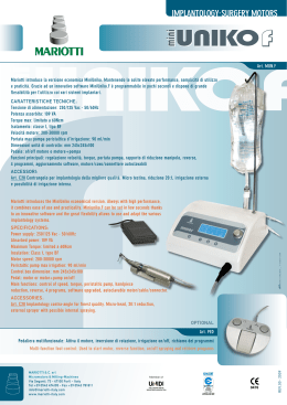
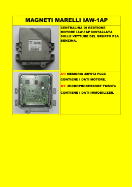
Catalogo Catalogue
MOTORI AUTOFRENANTI
BRAKE MOTORS
2
63 ... 200
Motore asincrono trifase
con freno a c.a.
Asynchronous three-phase
motor with a.c. brake
HFF
63 ... 200
Motore asincrono trifase
con freno a c.c.
Asynchronous three-phase
motor with d.c. brake
HFZ
63 ... 160S
Motore asincrono trifase (e monofase)
con freno di sicurezza a c.c.
Asynchronous three-phase (and singlephase) motor with d.c. safety brake
HFV
®
C
US
2005
Motori elettrici autofrenanti
Electric brake motors
Gamma di motori autofrenanti vasta e completa per tipologia (HFF,
HFZ, HFV), grandezza ed esecuzioni, idonea a risolvere tutte le problematiche degli azionamenti con motore asincrono trifase e
monofase autofrenante con freno a mancanza di alimentazione
Prodotto robusto e affidabile
Documentazione innovativa per completezza e rigore
Potenze 0,045 ... 37 kW
Singola polarità 2, 4, 6, 8 poli 230 Y 400 V 50 Hz (grandezze 63 ...
160S) e 400 V 50 Hz (grandezze 100 ... 200)
Doppia polarità 2.4, 4.6, 4.8, 6.8 poli 400 V 50 Hz (grandezze 63 ...
200) e 2.6, 2.8, 2.12 poli 400 V 50 Hz (grandezze 63 ... 132)
Grandezze 63 ... 132 anche con potenze superiori (contrassegnate da *)
a quelle previste dalle norme.
Classe isolamento F; classe sovratemperatura B/F per tutti i motori a
singola polarità con potenza normalizzata, F per i rimanenti
Forme costruttive IM B3 (grand. 80 ... 200 sempre predisposte), IM B5
normali e speciali, IM B14 e corrispondenti forme costruttive verticali
Protezione IP 54 per grand. 63 ... 160S e IP 55 per grand. 160 ... 200
Costruzione (elettrica e meccanica) particolarmente robusta per
sopportare le sollecitazioni termiche e torsionali alterne di avviamento
e di frenatura; cuscinetti adeguatamente dimensionati
Scudi e flange con attacchi di serraggio «in appoggio» e montati
sulla carcassa con accoppiamento «stretto»
Dimensionamento elettromagnetico opportunamente studiato per consentire elevata capacità di accelerazione (elevata freq. di avv.) e buona
regolarità di avviamento (curve caratteristiche poco «insellate»)
Motori trifase grandezze 80 ... 200, 2 e 4 poli, 400 V 50 Hz (solo
IC 411) a rendimento aumentato eff2.
Guarnizioni d’attrito senza amianto
Scatola morsettiera ampia e metallica, alimentazione freno indifferentemente diretta o separata
Idoneità al funzionamento con inverter
Ampia disponibilità di esecuzioni per ogni esigenza
I motori grandezze 63 ... 160S sono fornibili in esecuzione certi®
ficata a norme CSA e UL
Brake motors in a wide and comprehensive range of types (HFF,
HFZ, HFV), sizes and designs, suitable to solve every application
problem of the drives with asynchronous three-phase and singlephase brake motor with braking in case of failure of supply
Strong and reliable product
Innovating, complete and rigorous documentation
Powers 0,045 ... 37 kW
Single-speed 2, 4, 6, 8 poles 230 Y 400 V 50 Hz (sizes 63 ... 160S) and
400 V 50 Hz (sizes 100 ... 200)
Two-speed 2.4, 4.6, 4.8, 6.8 poles 400 V 50 Hz (sizes 63 ... 200) and 2.6,
2.8, 2.12 poles 400 V 50 Hz (sizes 63 ... 132)
Sizes 63 ... 132 available also with higher powers (marked by *) than
the ones foreseen by the standards.
Class F insulation; temperature rise class B/F for all single-speed motors
at standard power, F for remaining motors
Mounting positions IM B3 (sizes 80 ... 200 always pre-arranged), standard and
non-standard IM B5, IM B14 and corresponding vertical mounting positions
IP 54 protection for sizes 63 ... 160S and IP 55 for sizes 160 ... 200
Particularly strong construction (both electrical and mechanical) to
withstand alternating torsional and thermic stresses of starting and braking; duly proportioned bearings
«Supported» tightening attachments of endshields and flanges fitted
on casing with «tight» coupling
Electromagnetic sizing especially studied to allow high acceleration
capacity (high frequency of starting) and uniform starting (slightly
«sagged» characteristic curves)
Improved efficiency three-phase motors, sizes 80 ... 200, 2 and
4 poles, 400 V 50 Hz (IC 411 only), available according to eff2
class limits.
Asbestos-free friction surfaces
Wide metallic terminal box, possibility of direct or separate brake supply
Suitable for operation with inverter
Designs available for every application need
Motor sizes 63 ... 160S can be supplied in certified design to CSA
®
and UL standards
C
C
US
US
I motori HFZ sono fornibili in esecuzione certificata, per uso in
zone con atmosfere potenzialmente esplosive, secondo la direttiva ATEX 94/9/CE: categorie 3G e 3D (zone 2 e 22).
HFZ motors are available in certified design, for use in zone with
potentially explosive atmospheres according to directive ATEX
94/9/CE: categories 3G and 3D (zones 2 and 22).
HFF Motore autofrenante asincrono trifase con freno a c.a.
Doppia superficie frenante, momento frenante elevato (normalmente
Mf 2MN) e registrabile con continuità
Massima prontezza e precisione di sblocco e frenatura (caratteristici
del freno a c.a.) e massima frequenza di frenatura
Elevata capacità di lavoro di frenatura
Massima frequenza di avviamento per il motore (lo sblocco del freno è
talmente rapido da consentire un avviamento completamente libero
anche con elevate frequenze di avviamento)
Particolarmente idoneo a impieghi nei quali sono richieste frenature
potenti e rapidissime nonché elevato numero di interventi
HFF Asynchronous three-phase brake motor with a.c. brake
Double braking surface, high braking torque (usually Mf 2MN) and
adjustable with continuity
Maximum quickness and precision in releasing and braking (typical of
a.c. brake) and maximum frequency of braking
High braking capacity
Maximum frequency of starting for the motor (rapidity in brake releasing
allows a completely free start also at high frequencies of starting)
Particularly suitable for applications requiring strong and very rapid
brakings together with a high number of starts
HFZ Motore autofrenante asincrono trifase con freno a c.c.
Doppia superficie frenante, momento frenante proporzionato al
momento motore (normalmente Mf ≈ 2MN) e registrabile a gradini
Massima silenziosità e progressività di intervento (sia all’avviamento
che in frenata) grazie alla minore rapidità (tipica del freno a c.c.) dell’àncora (più leggera e meno veloce nell’impatto): il motore parte leggermente frenato quindi con maggiore progressività; buona rapidità di
sblocco e frenatura; possibilità di accentuare la rapidità, sia allo sblocco (con il raddrizzatore rapido) sia alla frenata, con apertura dell’alimentazione del lato c.c.
Elevata capacità di lavoro di frenatura ma inferiore a quella del tipo
HFF nel caso di elevatissime frequenze di intervento
Ampia disponibilità di esecuzioni speciali (volano, encoder, servoventilatore, servoventilatore ed encoder, leva di sblocco con ritorno automatico, protezioni superiori a IP 55: IP 56, IP 65.)
Particolarmente idoneo a impieghi nei quali sono richiesti frenate e
avviamenti regolari e silenziosi e, al tempo stesso, frenatura con buona
rapidità e precisione e numero elevato di interventi
HFZ Asynchronous three-phase brake motor with d.c. brake
Double braking surface, braking torque proportioned to motor torque
(usually Mf ≈ 2MN) and adjustable per step
Maximum reduced noise level and operation progressivity (both at starting and braking) thanks to a lower rapidity (typical of d.c. brake) of the
anchor (which is lighter and less quick in the impact): motor starts slightly braked i.e. with greater progressivity; good release and braking rapidity; possibility to increase rapidity, both in releasing (with rapid rectifier)
and braking, with supply opening on d.c. side
High braking capacity but lower than the one of HFF type in case of very
high frequencies of starting
Wide range of non-standard designs (flywheel, encoder, independent
cooling fan, independent cooling fan and encoder, hand lever for manual
release with automatic return, protections higher than IP 55: IP 56, IP 65.)
Particularly suitable for applications requiring regular and low-noise
starting and braking and, at the same time, braking with good rapidity
and precision and high number of starts
HFV Motore autofrenante asincrono trifase (e monofase) con
freno di sicurezza a c.c. con ingombro ridotto
Ingombro motore ridottissimo, quasi uguale a quello di un motore non
autofrenante; massima economicità
Singola superficie frenante, momento frenante fisso (normal. Mf ≈ MN)
Elevata capacità di lavoro di frenatura per singola frenata grazie alla ventola di ghisa (che funge anche da disco di frenatura) opportunamente
dimensionata che garantisce lo smaltimento di elevate energie di frenatura
Disponibile anche per alimentazione monofase
Particolarmente adatta alle macchine da taglio, per arresti di sicurezza, come freno di stazionamento, ecc.
HFV Asynchronous three-phase (and single-phase) brake motor
with d.c. safety brake with reduced overall dimension
Very reduced motor overall dimensions, which are nearly the same of a
non-braking motor; maximum economy
Single braking surface, fixed braking torque (usually Mf ≈ MN)
High braking capacity for each braking thanks to cast iron fan (which
also acts as brake disk) especially sized in order to achieve the dissipation of high braking energies
Also available for single-phase supply
Particularly suitable for cutting machines, safety stops, as parking
brake, etc.
2
63 ... 160S
160 ... 200
HFF
HFZ
HFV
63 ... 160S
160 ... 200
63 ... 160S
160 ... 200
63 ... 160S
Normale
Encoder
Servoventilatore
Standard
Encoder
Independent
cooling fan
Servoventilatore
ed encoder
Independent cooling
fan and encoder
Volano
Flywheel
3
Nella stesura del catalogo è stata dedicata la massima attenzione al
fine di assicurare l’accuratezza dei dati, tuttavia non si possono accettare responsabilità per eventuali errori, omissioni o dati non aggiornati.
Gli schemi di copertina raffigurano i motori completi di alcune esecuzioni a richiesta: albero motore bloccato assialmente (per HFF e
HFV), anelli di tenuta, leva di sblocco manuale con ritorno automatico, guaina antipolvere e V-ring.
4
Every care has been taken in the drawing up of the catalogue to
ensure the accuracy of the information contained in this publication,
however no responsibility can be accepted for any errors, omissions
or not updated data.
Cover schemes represent motors comprehensive of some designs
on request: driving shaft axially fastened (for HFF and HFV), seal
rings, lever for manual release with automatic return, dust-proof
gaiter and V-ring.
Indice
Index
1.
Simboli
1.
Symbols
6
2.
Designazione
2.
Designation
6
3.
Caratteristiche
3.
Specifications
7
3.1
3.2
3.3
3.4
3.5
3.6
3.7
3.8
3.9
4.
HFF Motore autofrenante asincrono
trifase con freno a c.a.
4.1
4.2
4.3
5.
7.
Esecuzioni speciali e accessori
US
CSA e UL,
5.
6.
7.
HFZ Asynchronous three-phase
brake motor with d.c. brake
8.
®
9.
US
CSA and UL,
HFZ
44
HFV
56
ATEX included)
Installation and maintenance
8.1
8.2
8.3
8.4
8.5
8.6
8.7
8.8
32
HFV motor specifications
HFV motor manufacturing programme
HFV motor dimensions
Non-standard designs and accessories
C
HFF
HFZ motor specifications
HFZ motor manufacturing programme
HFZ motor dimensions
HFV Asynchronous three-phase
(and single-phase) brake motor
with d.c. safety brake
(
18
HFF motor specifications
HFF motor manufacturing programme
HFF motor dimensions
6.1
6.2
6.3
Avvertenze generali sulla sicurezza
Installazione: indicazioni generali
Collegamento motore
Freno del motore HFF
Freno del motore HFZ
Freno del motore HFV
Collegamento equipaggiamenti ausiliari
Tavole delle parti di ricambio
Targa
HFF Asynchronous three-phase
brake motor with a.c. brake
5.1
5.2
5.3
ATEX)
Installazione e manutenzione
8.1
8.2
8.3
8.4
8.5
8.6
8.7
8.8
9.
®
C
Main specifications
Duty types
Verifying and evaluating calculations
Variations of nominal specifications
Radial and axial loads
Sound levels
Running with inverter
Tolerances
Specific standards
4.1
4.2
4.3
Caratteristiche specifiche motore HFV
Programma di fabbricazione motore HFV
Dimensioni motore HFV
(compreso
8.
4.
Caratteristiche specifiche motore HFZ
Programma di fabbricazione motore HFZ
Dimensioni motore HFZ
HFV Motore autofrenante asincrono
trifase (e monofase) con freno
di sicurezza a c.c.
6.1
6.2
6.3
3.1
3.2
3.3
3.4
3.5
3.6
3.7
3.8
3.9
Caratteristiche specifiche motore HFF
Programma di fabbricazione motore HFF
Dimensioni motore HFF
HFZ Motore autofrenante asincrono
trifase con freno a c.c.
5.1
5.2
5.3
6.
Caratteristiche generali
Tipi di servizio
Calcoli di verifica e di valutazione
Variazioni delle caratteristiche nominali
Carichi radiali e assiali
Livelli sonori
Funzionamento con inverter
Tolleranze
Norme specifiche
69
General safety instructions
Installation: general directions
Motor connection
HFF motor brake
HFZ motor brake
HFV motor brake
Auxiliary equipments connection
Spare parts tables
Name plate
81
5
1. Simboli
C
C
Cmax
cos
f
IN
IS
J0
JV
J
MN
MS
Mmax
Ma
Mf
Mrichiesto
nN
PN
Prichiesta
R
t1
t2
ta
tf
a
f
W1
Wf
z0
1. Symbols
–
[mm]
[mm]
–
–
declassamento del momento torcente;
consumo del disco freno (diminuzione di spessore);
massimo consumo consentito del disco freno;
fattore di potenza;
rendimento = rapporto tra potenza meccanica resa
e potenza elettrica assorbita;
[Hz]
frequenza;
[A]
corrente nominale;
[A]
corrente di spunto;
2
[kg m ] momento di inerzia (di massa) del motore;
2
[kg m ] momento di inerzia (di massa) aggiuntivo del volano nel caso di esecuzione W; valore da aggiungere a J0 per ottenere il momento d’inerzia complessivo del motore;
[kg m2] momento di inerzia (di massa) esterno (giunti, trasmissione, riduttore, macchina azionata) riferito all’asse motore;
[N m]
momento torcente nominale;
[N m]
momento torcente di spunto, con inserzione diretta;
[N m]
momento torcente massimo, con inserzione diretta;
[N m]
momento medio accelerante;
[N m]
momento frenante;
[N m]
momento torcente assorbito dalla macchina per
lavoro e attriti;
-1
[min ]
velocità nominale;
[kW]
potenza nominale;
[kW]
potenza assorbita dalla macchina riferita all’asse
motore;
–
rapporto di variazione della frequenza;
[ms]
ritardo di sblocco dell’àncora;
[ms]
ritardo di frenatura;
[s]
tempo di avviamento;
[s]
tempo di frenatura;
[rad]
angolo di rotazione in avviamento;
[rad]
angolo di rotazione in frenatura;
[MJ/mm] lavoro di attrito che genera una diminuzione di
spessore del disco freno di 1 mm;
[J]
lavori di attrito dissipato per ogni frenata;
[avv./h] numero massimo di avviamenti/h consentiti a vuoto del motore con rapporto di intermittenza del
50%.
2. Designazione
F
112 M 4
230.400-50 B3
Z
W 132 S 2.8
400-50 B5
V
90 L 4
230.400-50 B14
VM
80 B 2
230-50 B5R
f
IN
IS
J0
JV
J
MN
MS
Mmax
Ma
Mf
Mrequired
nN
PN
Prequired
R
t1
t2
ta
tf
a
f
W1
Wf
z0
torque derating;
brake disk wear (reduction of thickness);
maximum allowed brake disk wear;
power factor;
efficiency = ratio between mechanic power available and electric power absorbed;
[Hz]
frequency;
[A]
nominal current;
[A]
starting current;
2
[kg m ] moment of inertia (of mass) of the motor;
[kg m2] flywheel additional moment of inertia (of mass) in
case of W design; value to add to J0 to obtain total
motor moment of inertia;
[kg m2] external moment of inertia (of mass) (couplings,
transmission, gear reducer, driven machine)
referred to motor shaft;
[N m]
nominal torque;
[N m]
starting torque, with direct on-line start;
[N m]
maximum torque, with direct on-line start;
[N m]
mean acceleration torque;
[N m]
braking torque;
[N m]
torque absorbed by the machine through work
and frictions;
[min-1]
nominal speed;
[kW]
nominal power;
[kW]
power absorbed by the machine referred to motor
shaft;
–
frequency variation ratio;
[ms]
delay of anchor release;
[ms]
delay of braking;
[s]
starting time;
[s]
braking time;
[rad]
starting rotation angle;
[rad]
braking rotation angle;
[MJ/mm] work of friction generating a brake disk wear of 1
mm;
[J]
work of friction dissipated for each braking;
[starts/h] maximum number of no-load starts/h allowed by
motor with cyclic duration factor 50%.
MOTORE
MOTOR
HF
asincrono trifase
asynchronous three-phase
TIPO
TYPE
F
Z
V (VM)
autofrenante con freno a c.a.
autofrenante con freno a c.c.
autofrenante con freno di
sicurezza a c.c. (monofase)
brake motor with a.c. brake
brake motor with d.c. brake
brake motor with d.c. safety brake
(single-phase)
normale
con volano
standard
with flywheel
W
GRANDEZZA
SIZE
63 ... 200
NUMERO POLI
NUMBER OF POLES
2, 4, 6, 8
2.4, 4.6, 4.8, 6.8 per unico avvolgimento (YY.)
2.6, 2.8, 2.12,
per avvolgimenti separati (Y.Y)
4.6*), 6.8*)
ALIMENTAZIONE1)
SUPPLY1)
230.400-50
400-50
400-50
230-50
for single winding (YY.)
for separate windings (Y.Y)
230 Y400 V 50 Hz (63 ... 160S)
400 V 50 Hz (100 ... 200)
400 V 50 Hz per doppia polarità
230 V 50 Hz per monofase
230 Y400 V 50 Hz (63 ... 160S)
400 V 50 Hz (100 ... 200)
400 V 50 Hz for two-speed
230 V 50 Hz for single-phase
FORMA COSTRUTTIVA2) B3, B5, B14,
MOUNTING POSITION2) B5R, B5A
IM B3, IM B5, IM B14,
IM B5 speciali
IM B3, IM B5, IM B14,
non-standard IM B5
Esecuzione speciale
Non-standard design
codice, ved. cap. 7
code, see ch. 7
,... ,... ,...
,P2
,T ... ,L
,AX
,E25
1) Per frequenza e tensioni diverse da quelle indicate ved. cap. 7.(1).
2) Disponibili anche nelle corrispondenti forme costruttive ad asse verticale.
*) Indicare in «Esecuzione speciale» il codice «Due avvolgimenti separati».
6
–
[mm]
[mm]
–
–
2. Designation
ESECUZIONE
DESIGN
HF
HF
HF
HF
C
C
Cmax
cos
1) May frequency and voltage differ from those stated above, see ch. 7.(1).
2) Also available relevant mounting positions with vertical shaft.
*) Indicate in «Non-standard design»: «Two separate windings» code.
3. Caratteristiche
3. Specifications
3.1 Caratteristiche generali
3.1 Main specifications
Motori elettrici autofrenanti (freno a mancanza di alimentazione)
in 3 tipi:
HFF, motore asincrono trifase autofrenante con freno a c.a. a doppia superficie frenante, grandezze 63 ... 200;
HFZ, motore asincrono trifase autofrenante con freno a c.c. a doppia superficie frenante, grandezze 63 ... 200;
HFV, motore asincrono trifase (e monofase) autofrenante con freno
di sicurezza a c.c., a singola superficie frenante, con ingombro
ridotto, grandezze 63 ... 160S.
Motore normalizzato con rotore a gabbia chiuso ventilato esternamente (metodo di raffreddamento IC 411), a singola polarità o a doppia polarità secondo tabelle seguenti:
Electric brake motors (braking in case of failure of supply) available in 3 types:
HFF, asynchronous three-phase brake motor with a.c. brake with
double braking surface, sizes 63 ... 200;
HFZ, asynchronous three-phase brake motor with d.c. brake with
double braking surface, sizes 63 ... 200;
HFV, asynchronous three-phase (and single-phase) brake motor
with d.c. safety brake, with single braking surface, with reduced
overall dimensions, sizes 63 ... 160S.
Standardised motor with cage rotor, totally enclosed, externally
ventilated (cooling system IC 411), single-speed or two-speed
according to following tables:
motori a singola polarità (a una velocità)
N. poli
Avvolgimento
Number
Winding
of poles
trifase Y
three-phase Y
100 ... 200
400 V ±5%1)
B/F2) (usually), F
monofase - single-phase
63 ... 100
230 V
F
Grand. motore
Motor size
two-speed motors (two speeds)
Alimentazione standard
Standard supply
2, 4, 6, 8
2, 4, 6
motori a doppia polarità (a due velocità)
N. poli
Avvolgimento
Number
Winding
of poles
2.4, 4.8
4.6
6.8
2.6
2.8
2.12
4.6
6.8
single-speed motors (one speed)
Alimentazione standard
Classe - Class
Standard supply
isolamento
sovratemperatura
insulation
temperature rise
Grand. motore
Motor size
unico
avvolgimento
single winding
YY. Dahlander
YY. PAM
due avvolgi- Y.Y
menti separati
two separate
windings
63 ... 160S
63
63
80
71
63
80
71
80
...
...
...
...
...
...
...
...
200S
160S
132S
132S
132S
132S
200S
200S
50 Hz
230 Y400 V ±5%1)
50 Hz
400 V
F
B/F2) (normalmente), F
Classe - Class
isolamento
insulation
sovratemperatura
temperature rise
F
F
1) Campo di tensione nominale motore; per i limiti massimo e minimo di alimentazione
motore considerare un ulteriore ± 5%, es.: un motore 230 Y 400 V con campo di tensione ± 5% è idoneo per tensioni nominali di rete fino a 220 Y 380 V e 240 Y 415 V.
Per altri valori di alimentazione ved. cap. 7.(1).
2) Sovratemperatura intermedia fra B e F.
1) Nominal voltage range of motor; for maximum and minimum motor supply limits consider a further ± 5%, e.g.: a 230 Y 400 V motor with voltage range ± 5% is suitable for
nominal mains voltages up to 220 Y 380 V and 240 Y 415 V. For other values of supply see ch. 7.(1).
2) Mean temperature rise between B and F.
Potenza resa in servizio continuo (S1) e riferita a tensione e frequenza nominali, temperatura ambiente di -15 +40 °C e altitudine
massima 1 000 m.
Motori a rendimento aumentato eff2, trifase, a 2 e 4 poli, 400
V 50 Hz (solo IC 411), grandezze 80 ... 200.
Alimentazione nominale: 230 Y400 V 50 Hz grandezze 80 ... 160S,
400 V 50 Hz grandezze 100 ... 200.
Le targhe motore riportano il marchio registrato
.
Protezione IP 54 per grandezze 63 ... 160S, IP 55 per grandezze
160 ... 200; scatola morsettiera IP 55; a richiesta protezioni superiori, ved. cap.7.
Forme costruttive IM B3, IM B5, IM B14; i motori possono funzionare
anche nelle corrispondenti forme costruttive ad asse verticale, rispettivamente (ved. tabella seguente): IM V5 e IM V6, IM V1 e IM V3, IM V18
e IM V19; in targa rimane comunque indicata la designazione della
forma costruttiva ad asse orizzontale escluso il caso di motori con fori
scarico condensa, ved. cap. 7.(8). I motori HFV sottoposti a una forza
assiale in direzione uscente lato comando (es. motore ad asse verticale in basso con masse sospese all’albero) debbono essere richiesti
in esecuzione «Albero motore bloccato assialmente» ved. cap. 7.(2).
Rated power delivered on continuous duty (S1) and referred to
nominal voltage and frequency, ambient temperature -15 +40 °C
and maximum altitude 1 000 m.
Improved efficiency three-phase motor, 2 and 4 poles, 400
V 50 Hz (IC 411 only), sizes 80 ... 200.
Nominal supply: 230 Y400 V 50 Hz sizes 80 ... 160S, 400 V 50 Hz
sizes 100 ... 200.
Registered trade mark
on motor name plates.
IP 54 protection for sizes 63 ... 160S, IP 55 for sizes 160 ... 200; terminal box IP 55; on request higher protections, see ch. 7.
IM B31)
IM V5
IM V6
IM B5
IM V1
1) Il motore può funzionare anche nelle forme costruttive IM B6, IM B7 e IM B8; in targa
rimane indicata la forma costruttiva IM B3.
Mounting positions IM B3, IM B5, IM B14; motors can also operate in the relevant mounting positions with vertical shaft, which are
respectively (see following table): IM V5 and IM V6, IM V1 and IM
V3, IM V18 and IM V19; the name plate shows the designation of
mounting position with horizontal shaft excluding motors having
condensate drain holes, see ch. 7.(8). HFV motors subjected to an
axial force in drive end output direction (e.g. motor with vertical shaft
downwards with overhung masses to the shaft) have to be requested with «Driving shaft axially fastened» design, see ch. 7.(2).
IM V3
IM B14
IM V18
IM V19
1) Motor can also operate in the mounting positions IM B6, IM B7 and IM B8; the name
plate shows the IM B3 mounting position.
7
3. Caratteristiche
3. Specifications
Dimensioni principali di accoppiamento delle forme costruttive
con flangia
Main mating dimensions of the mounting positions with flange
Forma costruttiva
Mounting position
Estremità d’albero Ø D x E - Flangia Ø P – Shaft end Ø D x E - Flange Ø P
Grandezza motore - Motor size
IM
63
71
80
90
100, 112
132
160
11 x 23 - 140 14 x 30 - 160 19 x 40 - 200 24 x 50 - 200 28 x 60 - 250 38 x 80 - 300 42x110-350
180
200
48x110-350
55x110-400
–
11 x 23 - 140 14 x 30 - 160 19 x 40 - 2002) 24 x 50 - 200 28 x 60 - 250 38x 80-300
–
48x110-350
–
14 x 30 - 140 19 x 40 - 160
–
–
–
–
–
28 x 60 - 200 38 x 80 - 250 42x110-300
11 x 23 - 90 14 x 30 - 105 19 x 40 - 120 24 x 50 - 140 28 x 60 - 160 38 x 80 - 200
–
1) Il cuscinetto lato comando è situato particolarmente vicino alla battuta dell’albero anche
per le forme costruttive IM B5 speciali per garantire rigidezza e sopportazione elevate.
2) Forma costruttiva non prevista per motore 90S.
1) Drive end bearing is particularly near the shaft shoulder, also for non-standard IM B5
mounting positions in order to achieve high rigidity and withstanding.
2) Mounting position not foreseen for motor 90S.
Carcassa di lega leggera pressofusa; per forma costruttiva IM B3:
con piedi integrali (grandezze 63 e 71) o riportati (grandezze 80 ...
200) montabili su tre lati.
Scudo lato comando (o flangia) e lato opposto comando di ghisa o di lega leggera (ved. tabella sottoriportata).
Scudi e flange con attacchi di serraggio «in appoggio» e montati
sulla carcassa con accoppiamento «stretto».
Cuscinetti volventi a sfere (ved. tabella sottoriportata) lubrificati «a
vita» in assenza di inquinamento dall’esterno; molla di precarico.
Casing in pressure diecast light alloy; for mounting position IM B3:
with integral (sizes 63 and 71) or inserted feet (sizes 80 ... 200)
which can be mounted on three sides.
Drive end (or flange) and non-drive end endshield in cast iron or
light alloy (see table below).
«Supported» tightening attachments of endshields and flanges
fitted on casing with «tight» coupling.
Ball bearings (see table below) lubricated «for life» assuming pollution-free surroundings; preload spring.
Grand. motore
Motor size
Cuscinetti e materiali scudi
Bearings and endshields material
lato comando - drive end
HFF
63
71
80
90S
90L
100
112M ... MB
112MC
132
160S
160, 180M
180L
200
LL
LL
LL
LL
LL
LL
LL
LL
LL4)
G
LL5)
G
G
lato opposto comando - non-drive end
HFZ
6202 2ZC
6203 2ZC
6204 2ZC
6005 2ZC
6205 2ZC
6206 2ZC
6206 2ZC
42061)0C0
6308 2ZC
6309 2ZC
6310 ZC3
6310 ZC3
6312 ZC3
LL
LL
LL
LL
LL
LL
LL
LL
LL4)
G
LL5)
G
G
HFV
6202 2ZC
6203 2ZC
6204 2ZC
6005 2ZC
6205 2ZC
6206 2ZC
42061)000
42061)000
6308 2ZC
6309 2ZC
6310 ZC3
6310 ZC3
6312 ZC3
LL
LL
LL
LL
LL
LL
LL
LL
LL4)
G
–
–
–
HFF
6202 2Z
6203 2Z
6204 2Z
6005 2Z
6205 2Z
6206 2Z
6206 2Z
42061) C
6308 2Z
6309 2Z
–
–
–
6202 2ZCC
6203 2ZCC
6204 2ZCC
6204 2ZCC
6205 2ZCC
6206 2ZCC
6206 2ZCC
6206 2ZCC
6308 2ZCC
6308 2ZCC
6309 2ZC3
6310 2ZC3
6310 2ZC3
HFZ
LL3)
LL3)
LL3)
LL3)
LL3)
LL3)
LL3)
LL3)
LL3)
LL3)
G
G
G
6202 2RSC
6203 2RSC
6204 2RSC
6204 2RSC
6205 2RSC
6306 2RSC
6306 2RSC
6306 2RSC
6308 2RSC
6308 2RSC
6309 2ZC3
6310 2ZC3
6310 2ZC3
HFV
G
G
G
G
G
G
G
G
G
G
G
G
G
6202 2Z..
6203 2Z..
6204 2Z..
6204 2Z..
6205 2Z..
6206 2Z..
6206 2Z2)
6306 2Z..
6308 2Z..
6308 2Z..
–
–
–
G
LL
LL
LL
LL
LL
LL2)
G
G
G
–
–
–
LL = lega leggera G = ghisa
1) Con schermi metallici.
2) 6306 2Z e scudo di ghisa per freno tipo VG (ved. p.ti 6.1 e 6.2).
3) Flangia di frenatura di lega leggera con inserto di acciaio nella pista di frenatura.
4) Di ghisa per IM B14 e IM B5R.
5) Di ghisa per IM B5.
LL = light alloy G = cast iron
1) With metallic shields.
2) 6306 2Z and endshield in cast iron for brake type VG (see points 6.1 and 6.2).
3) Brake flange in light alloy with steel insert in braking track.
4) In cast iron for IM B14 and IM B5R.
5) In cast iron for IM B5.
Albero motore: per HFF e HFZ di acciaio 39 NiCrMo3 bonificato o
C43 secondo la grandezza, per HFV C43. A richiesta «Albero motore bloccato assialmente» sullo scudo posteriore, ved. cap. 7.(2) (di
serie per HFF 160 e HFZ). Estremità d’albero cilindriche con linguetta forma A (arrotondata) e foro filettato in testa (ved. tabella
dove: d = foro filettato in testa; bxhxl = dimensioni linguetta).
Driving shaft: for HFF and HFZ in through-hardened steel
39 NiCrMo3 or C43 depending on size, for HFV C43. On request
«Driving shaft axially fastened» on rear endshield, see ch. 7.(2)
(standard for HFF 160 and HFZ). Cylindrical shaft ends with Ashape (rounded) key and tapped butt-end hole (see table, where:
d = tapped butt-end hole; bxhxl = key dimensions).
Estremità d’albero Ø x E - Shaft end Ø x E
Ø 11x23
Ø 14x30
Ø19x40
Ø 24x50
Ø 38x80
Ø 42x110
Ø 48x110
Ø 55x110
d
M4
M5
M6
M8
M10
M12
M16
M16
M20
bxhxl
4x4x18
5x5x25
6x6x32
8x7x40
8x7x50
10x8x70
12x8x100
14x9x100
16x10x100
Copriventola di lamiera d’acciaio.
Ventola di raffreddamento a pale radiali di materiale termoplastico
(per motori HFV è di ghisa ved. p.to 6.1).
Scatola morsettiera (protezione IP 55) completa di un bocchettone
pressacavo e tappi filettati, di lega leggera, con accesso cavi bilaterale (grandezze 63 ... 90, un foro per parte; grandezze 100 ... 160S, due
fori per parte) o di lamiera zincata orientabile di 90° in 90° (grandezze
160 ... 200, due fori sullo stesso lato). Posizione opposta ai piedi per
forma costruttiva IM B3 (come raffigurato negli schemi dimensionali ai
p.ti 4.3, 5.3, 6.3); a richiesta laterale destra o sinistra (ved. cap. 7.(14)).
Coprimorsettiera pressofuso di lega leggera o di lamiera zincata.
8
Ø 28x60
Steel fan cover.
Thermoplastic cooling fan with radial vanes (for HFV motors it is in
cast iron see point 6.1).
Light alloy terminal box (IP 55 protection) with cable gland and
threaded plugs, with cable openings on both sides (sizes 63 ... 90,
one hole per side; sizes 100 ... 160S, two holes per side) or made of
galvanized plate, positions 90° apart (sizes 160 ... 200, two holes on
the same side). Position opposite to feet for mounting position IM
B3 (see dimensional schemes at points 4.3, 5.3, 6.3); on request
available on one side right or left (see ch. 7.(14)). Pressure diecast
light alloy or galvanized plate terminal box cover.
3. Caratteristiche
3. Specifications
Morsettiera a 6 morsetti (a richiesta 9 o 12,
Terminal block with 6 terminals (on
Grand. motore
Morsettiera
Anello di tenuta
request 9 or 12, see ch. 7. (10)) for motor
ved. cap. 7.(10)) per l’alimentazione del moMotor
size
Terminal
block
Seal
ring
supply; terminal dimensions in the table on
tore; per morsetti ved. tabella a fianco.
3)
the side.
morsetti Ø cavo max
Morsetto di terra all’interno della scatola
Earth terminal located inside terminal box;
morsettiera; predisposizione per il montagterminals Ø cable max3)
prearranged for the installation of a further
gio di un ulteriore morsetto di terra sulla car1)
mm
2)
earth terminal on casing (sizes 160 ... 200).
cassa (grandezze 160 ... 200).
63
M4
10
15 x 30 x 4,5
Brake supply: with auxiliary terminal block
Alimentazione freno: con morsettiera au71
M4
13
17 x 32 x 5,5
with 6 terminals (for HFF) or with rectifier
siliaria a 6 morsetti (per HFF) o con raddriz80
M4
13
20 x 35 x 7,5
(with HFZ or HFV) laying in terminal box
zatore (per HFZ o HFV) fissato alla scatola
having 2 terminals for cable connection for
morsettiera con 2 morsetti per capicorda
90S
M4
13
25 x 35 x 7,5
rectifier supply and only for HFZ 2 for
per alimentazione raddrizzatore e solo per
90L
M4
17
25 x 46 x 7,5
external contact of fast braking plus 3 auxHFZ 2 per contatto esterno di frenatura ra100, 112
M5
17
30 x 50 x 7,5
iliary for independent cooling fan or therpida più 3 ausiliari per servoventilatore o
132
M6
21
40
x
60
x
10,5
mal probes, if any); possible brake supply
sonde termiche eventuali; possibilità di ali160S
M6
21
45
x
65
x
10,5
directly from motor terminal block or
mentazione del freno sia direttamente dal4)
160
...
200
M8
35
–
separately (to use for: two-speed motors,
la morsettiera motore sia da linea separa1) 6 morsetti per collegamento con capocorda.
motors supplied by inverter, separate drive
ta (da utilizzare per: motori a doppia pola2) Montabile a richiesta sul lato comando, ved. cap. 7.(12).
needs of motor and brake, etc.).
rità, motori alimentati con inverter, esigenze
3) Per numero fori ved. p.ti 4.3, 5.3, 6.3.
di comando separato di motore e freno,
Brake can be supplied, also at motor stand4) Tenuta a labirinto di serie.
1) 6 terminals for cable terminal connection.
ecc.). Il freno può restare alimentato, anche
still, with no time limitations.
2) Available on drive end, if requested, see ch. 7.(12).
a motore fermo, per un tempo illimitato.
Pressure diecast cage rotor in aluminium or
3) For number of holes see points 4.3, 5.3, 6.3.
4) Labyrinth seal supplied as standard.
resistive aluminium (2.4 HFZ, 2.6, 2.8, 2.12
Rotore a gabbia pressofuso di alluminio o di
for sizes 160S and for all single-phase).
alluminio resistivo (2.4 HFZ, 2.6, 2.8, 2.12 per
grandezze 160S e per tutti i monofase).
Stator winding with class H copper conductor insulation, insulated with double coat, type of impregnation
Avvolgimento statorico con filo di rame in classe isolamento H, isowith resin of class H (F for sizes 160); other materials are of classlato con doppio smalto, sistema di impregnazione con resina in clases F and H for a class F insulation system.
se H (F grand. 160); gli altri materiali sono in classe F e H per un
sistema isolante in classe F.
Materials and type of impregnation allow use in tropical climates
without further treatments.
Materiali e tipo di impregnazione consentono l’impiego in clima tropicale senza ulteriori trattamenti.
Rotor dynamic balancing: vibration velocity under standard rating
N. Motors are balanced with half key inserted into shaft extension.
Equilibratura dinamica rotore: intensità di vibrazione secondo la
classe normale N. I motori sono equilibrati con mezza linguetta insePaint: water-soluble, colour blue RAL 5010 DIN 1843, unaffected by
rita nella estremità d’albero.
normal industrial environments and suitable for further finishings
with single-compound synthetic paints.
Verniciatura con smalto idrosolubile, colore blu RAL 5010 DIN
1843, idonea a resistere ai normali ambienti industriali e a consentiFor non-standard designs and accessories see ch. 7.
re ulteriori finiture con vernici sintetiche monocomponenti.
Compliance with European Directives
Per esecuzioni speciali ed accessori ved. cap. 7.
– «Low Voltage» 73/23/EEC directive (modified by directive 93/68):
Conformità alle Direttive Europee
motors shown on present catalogue meet the requirements of a.m.
directive and are CE marked on name plate.
– Direttiva «Bassa tensione» 73/23/CEE (modificata dalla direttiva
93/68): i motori del presente catalogo sono conformi alla direttiva
– «Electromagnetic Compatibility (EMC)» 89/336/EEC directive
e riportano per questo il marchio CE in targa.
(modified by directives 92/31, 93/68); this directive has not to be
obligatorily applied on the products of present catalogue; the
– Direttiva «Compatibilità elettromagnetica (EMC)» 89/336/CEE
responsibility of the compliance with the directive for a complete
(modificata dalle direttive 92/31, 93/68); la direttiva non è obbligainstallation is of the machine manufacturer; motors running in contoriamente applicabile ai prodotti del presente catalogo; la retinuous duty and supplied from mains comply with EN 50081 and
sponsabilità della conformità alla direttiva di un’installazione comEN 50082 general standards; for further information about a corpleta è a carico del costruttore della macchina; i motori funzionanrect installation to EMC see ch. 7.((28), (29)) and 8.
ti in servizio continuo e alimentati da rete sono conformi alle norme generali EN 50081 e EN 50082; per indicazioni su una corret– «Machinery» 98/37/EEC directive cannot be applied to electric
ta installazione ai fini EMC ved. cap. 7.((28), (29)) e 8.
motors of present catalogue (see also ch. 8).
– Direttiva «Macchine» 98/37/CEE: non applicabile ai motori elettrici del presente catalogo (ved. anche cap. 8).
3.2 Tipi di servizio
3.2 Duty types
Servizio di durata limitata (S2) e servizio intermittente periodico (S3); servizi S4 ... S10
Per servizi di tipo S2 ... S10 è possibile incrementare la potenza del
motore secondo la tabella seguente (per monofase interpellarci); il
momento torcente di spunto resta invariato.
Short time duty (S2) and intermittent periodic duty (S3); duty
types S4 ... S10
In case of a duty-requirement type S2 ... S10 the motor power can
be increased as per the following table (for single-phase consult us);
starting torque keeps unchanged.
Servizio di durata limitata (S2). – Funzionamento a carico costante per una durata
determinata, minore di quella necessaria per raggiungere l’equilibrio termico, seguito da
un tempo di riposo di durata sufficiente a ristabilire nel motore la temperatura ambiente.
Servizio intermittente periodico (S3). – Funzionamento secondo una serie di cicli identici, ciascuno comprendente un tempo di funzionamento a carico costante e un tempo di
riposo. Inoltre in questo servizio le punte di corrente all’avviamento non devono influenzare il riscaldamento del motore in modo sensibile.
N
Rapporto di intermittenza =
· 100%
N+R
N è il tempo di funzionamento a carico costante,
R è il tempo di riposo e N + R = 10 min (se maggiore interpellarci).
Short time duty (S2). – Running at constant load for a given period of time less than that
necessary to reach normal running temperature, followed by a rest period long enough for
motor’s return to ambient temperature.
Intermittent periodic duty (S3). – Succession of identical work cycles consisting of a
period of running at constant load and a rest period. Current peaks on starting are not to
be of an order that will influence motor heat to any significant extent.
N
· 100%
N+R
N being running time at constant load,
R the rest period and N + R = 10 min (if longer consult us).
Cyclic duration factor =
Grandezza motore1) - Motor size1)
Servizio - Duty
S2
durata del servizio
duration of running
S3
rapporto di intermittenza
cyclic duration factor
S4 ... S10
1) Per motori identificati con il simbolo ai p.ti 4.2, 5.2 e 6.2 interpellarci.
90
60
30
10
min
min
min
min
60%
40%
25%
15%
63 ... 90
100 ... 160S
160 ... 200
1
1
1,12
1,25
1
1,06
1,18
1,25
1,06
1,12
1,25
1,32
1,12
1,18
1,25
1,32
interpellarci - consult us
1) For motors identified by at points 4.2, 5.2 and 6.2 consult us.
9
3. Caratteristiche
3. Specifications
3.3 Calcoli di verifica e valutazione
3.3 Verifying and evaluating calculations
Le principali verifiche necessarie affinché motore e freno possano
soddisfare le esigenze applicative consistono in:
– dati il momento torcente richiesto e le inerzie applicate, la frequenza di avviamento non deve superare il valore massimo ammesso dagli avvolgimenti del motore senza che si abbiano surriscaldamenti;
– dato il numero di frenate/h, il lavoro di attrito per ogni frenatura
non deve superare il massimo valore ammesso dalla guarnizione
d’attrito.
Ved. sotto le modalità di verifica.
Main necessary verifications so that motor and brake can satisfy
application needs are:
– given required torque and applied inertiae, frequency of starting
has not to exceed maximum value permissible by motor windings
without overheatings;
– given number of brakings/h, work of friction for each braking
has not to exceed maximum permissible value of friction surface.
See below verification modalities.
Frequenza massima di avviamento z
Orientativamente la massima frequenza di avviamento z, per un
tempo di avviamento 0,5 1 s e con inserzione diretta, è di 125
avv./h per grandezze 63 ... 90, 63 avv./h per grandezze 100 ... 160S,
16 avv./h per grandezze 160 ... 200; dimezzare i valori per motori
HFFW, HFZW, HFV, i quali, avendo J0 più elevato (per ottenere avviamenti e arresti progressivi), possono fare un numero minore di avviamenti a parità di condizioni.
Quando è necessaria una frequenza di avviamento superiore verificare che:
J0
Prichiesta 2
z z0 ·
·K· 1· 0,6
J0 + J
PN
Maximum frequency of starting z
As a guide, maximum frequency of starting z, for a starting time 0,5
1 s and with direct on-line start, is 125 starts/h for sizes 63 ... 90,
63 starts/h for sizes 100 ... 160S, 16 starts/h for sizes 160 ... 200;
halve the values for motors HFFW, HFZW, HFV, which, having a
higher J0 (to get progressive starts and stops), can have a lower
number of starts at the same conditions.
When it is necessary to have a higher frequency of starting, verify that:
K=1
se il motore, durante l’avviamento, deve vincere solo carichi inerziali;
K = 0,63 se il motore, durante l’avviamento, deve vincere anche carichi resistenti di attrito, di lavoro, di sollevamento, ecc.
Per motori a doppia polarità la verifica del valore z va fatta:
– per la polarità bassa, se l’avviamento è a velocità alta, e considerando il relativo valore di z0 e PN;
– per entrambe le polarità se l’avviamento è a velocità bassa con successiva commutazione a velocità alta e considerando i rispettivi valori di z0 e PN, ma moltiplicando il valore di z0 della polarità bassa per
2 (2.4, 4.8, 4.6, 6.8 poli), 1,8 (2.6 poli), 1,4 (2.8 poli), 1,25 (2.12 poli).
In caso di risultati insoddisfacenti o in presenza di frenature ipersincrone frequenti la verifica può essere fatta con formule più dettagliate: interpellarci.
Per HFZ, nel caso di frequenza di avviamento elevata (z/z0 0,2 polarità unica, z/z0 0,3 doppia polarità, purché z 1100 avv./h) prevedere l’impiego del raddrizzatore rapido RR1 (ved. cap. 7.(27)) per
i motori che già non ne sono dotati.
K=1
if motor, during the starting, must only overcome inertial
loads;
K = 0,63 if motor, during the starting, must also overcome resistent
friction, work, lifting loads, etc.
For two-speed motors, verification of z value is as follows:
– for the lower set of poles, if starting is at high speed, taking into
account relative z0 and PN values;
– for both sets of poles, if starting is at low speed with subsequent
switch to high speed, taking into account relative z0 and PN values,
though multiplying the z0 value of the lower set of poles by 2 (2.4,
4.8, 4.6, 6.8 poles), 1,8 (2.6 poles), 1,4 (2.8 poles), 1,25 (2.12 poles).
Where results are unsatisfactory or where frequent hypersynchronous brakings occur, more detailed verification formulae can be
utilised: consult us.
For HFZ, in case of high frequency of starting (z/z0 0,2 singlespeed, z/z0 0,3 two-speed, provided that z 1100 starts/h) foresee the application of a rapid rectifier RR1 (see ch. 7.(27)) if motors
do not have it.
Massimo lavoro di attrito per ogni frenatura Wf
Nel caso di un numero elevato di frenature/h (z 0,2 z0) o di inerzie
applicate molto elevate (J 10 J0) è necessario verificare che il
lavoro di attrito per ogni frenatura non superi il massimo valore
ammesso Wfmax indicato ai p.ti 4.1, 5.1, 6.1 in funzione della frequenza di frenatura (per valori intermedi di frequenza impiegare il
valore più basso o, all’occorrenza, interpolare):
Maximum work of friction for each braking Wf
In case of a high number of brakings/h (z 0,2 z0) or very high inertiae applied (J 10 J0) it is necessary to verify that work of friction
for each braking does not exceed maximum permissible value of
Wfmax as shown at points 4.1, 5.1, 6.1 according to frequency of
braking (for intermediate values of frequency apply the lowest value
and interpolate, if necessary):
[ (
)
]
Wfmax Mf ·
per il calcolo di
f ved. sotto.
Tempo di avviamento ta e angolo di rotazione del motore
(J0 + J) · nN
t ·n
ta =
[s]
a = a N [rad]
9,55 · (MS - Mrichiesto)
19,1
z z0 ·
f
[ (
Prequired
PN
) · 0,6]
2
[J]
for the calculation of
a
J0
·K· 1J0 + J
f see below.
Starting time ta and motor rotation angle a
(J0 + J) · nN
t ·n
ta =
[s]
a = a N
9,55 · (MS - Mrequired)
19,1
[rad]
Per calcoli più accurati sostituire a MS il momento medio accelerante, normalmente
Ma ≈ 0,85 · MS.
For more accurate calculations replace MS with a mean acceleration torque, usually
Ma ≈ 0,85 · MS.
Tempo di frenatura tf e angolo di rotazione del motore f
(J0 + J) · nN
t ·n
tf =
[s]
f = f N [rad]
9,55 · (Mf + Mrichiesto)
19,1
Se Mrichiesto tende a trainare il motore (esempio carico sospeso) introdurre nelle formule un numero negativo.
La ripetitività di frenatura al variare della temperatura del freno e
dello stato di usura della guarnizione di attrito è, entro i limiti normali del traferro e dell’umidità ambiente e con adeguata apparecchiatura elettrica, circa ± 0,1 · f.
Braking time tf and motor rotation angle f
(J0 + J) · nN
t ·n
tf =
[s]
f = f N [rad]
9,55 · (Mf + Mrequired)
19,1
If Mrequired tends to pull the motor (e.g. overhung load) introduce a
negative number in the formulae.
Assuming a regular air-gap and ambient humidity and utilising suitable electrical equipment, repetition of the braking action, as affected by variaton in temperature of the brake and by the state of wear
of friction surface, is approx. ± 0,1 · f.
Durata della guarnizione di attrito
Orientativamente il numero di frenature tra due registrazioni del
traferro vale:
Duration of friction surface
As a guide, the number of brakings permissible between successive adjustments of the air-gap is given by the formula:
W1 · C · 106
Mf · f
per il calcolo della periodicità di registrazione del traferro, il valore di C è dato dalla differenza tra i valori max e min del traferro; per
il calcolo della durata totale del disco freno, il valore C è dato dal
valore massimo di consumo Cmax (ved. p.ti 4.1, 5.1, 6.1).
10
;
for the calculation of periodical air-gap adjustment, C value is
given by the difference between max and min values of the air-gap;
for total brake disk life calculation, C value is given by the maximum wear value Cmax (see points 4.1, 5.1, 6.1).
3. Caratteristiche
3. Specifications
3.4 Variazioni delle caratteristiche nominali
3.4 Variations of nominal specifications
Alimentazione diversa dai valori nominali
Le caratteristiche funzionali di un motore trifase alimentato a tensione e/o frequenza diverse da quelle nominali di avvolgimento si possono ottenere approssimativamente moltiplicando i valori nominali
dei p.ti 4.2, 5.2, 6.2 per i fattori correttivi indicati in tabella validi per
la sola parte motore (la targa riporta comunque i dati nominali di avvolgimento):
Supply differs from nominal values
Functional specifications of a three-phase motor supplied at voltage and/or frequency differing from the nominal ones can be
obtained approximately by multiplying nominal data of points 4.2,
5.2, 6.2 by correction factors stated in the table valid for the motor
only (however, the name plate contains the nominal winding data):
Alimentazione nominale
Nominal supply
Alimentazione alternativa
Alternative supply
Frequenza [Hz] Tensione [V]
Frequency [Hz] Voltage [V]
230 Y400 V 50 Hz
400 V 50 Hz
Fattori moltiplicativi dei valori di catalogo
Multiplicative factors of catalogue value
PN
nN
IN
MN
IS
MS, Mmax
50
220 Y380
240 Y415
1,0
1,0
1
1
0,95 1,05
0,95 1,05
1
1
0,96
1,04
0,92
1,08
60
220
255
265
277
1,0
1,1
1,15÷1,13)
1,21÷1,154)
1,19
1,2
1,2
1,2
0,95 1,05
0,95 1
0,95 1,05
1
0,83
0,92
0,96 ÷ 0,923)
1,09 ÷ 0,964)
0,79
0,92
0,96
1
0,63
0,84
0,92
1
50
380
415
1,0
1,0
1
1
0,95 1,05
0,95 1,05
1
1
0,96
1,04
0,92
1,08
60
3801)
4401) 2)
4602)
4802)
1,0
1,1
1,15÷1,13)
1,21÷1,154)
1,19
1,2
1,2
1,2
0,95 1,05
0,95 1
0,95 1,05
1
0,83
0,92
0,96 ÷ 0,923)
1,01 ÷ 0,964)
0,79
0,92
0,96
1
0,63
0,84
0,92
1
Y3801)
Y4401) 2)
Y4602)
Y4802)
1) Fino alla grandezza 132MB, il motore normale (escluso quello a doppia polarità) può
funzionare anche con questo tipo di alimentazione purché si accettino sovratemperature superiori, non si abbiano avviamenti a pieno carico e la richiesta di potenza non sia
esasperata; non targato per questo tipo di alimentazione.
2) Il freno deve essere opportunamente predisposto al valore di tensione indicato, ved. cap. 7.(1).
3) Valore valido per grandezza 160M.
4) Valore valido per grandezze 160L 4, 180M 4 e 200L 4.
1) Up to size 132MB, standard motor (two-speed motor excluded) can also operate with
this supply provided that higher temperature rise values are acceptable without on-load
starts and that the power requirement is not unduly demanding; this supply is not shown
on motor name plate.
2) The brake must be especially prepared for the stated voltage values, see ch. 7.(1).
3) Value valid for size 160M.
4) Value valid for sizes 160L 4, 180M 4 and 200L 4.
Potenza resa con elevata temperatura ambiente o elevata altitudine
Qualora il motore debba funzionare in ambiente a temperatura superiore a 40 °C o ad altitudine sul livello del mare superiore a 1 000 m,
deve essere declassato in accordo con le seguenti tabelle:
Power available with high ambient temperature or high altitude
If motor must run in an ambient temperature higher than 40 °C or at
altitude at sea level higher than 1 000 m, it must be derated according to following tables:
Temperatura ambiente - Ambient temperature [°C]
30
40
45
50
55
60
P/PN [%]
106
100
96,5
93
90
86,5
Altitudine s.l.m. - Altitude a.s.l. [m]
1 000
1 500
2 000
2 500
3 000
3 500
4 000
P/PN [%]
100
96
92
88
84
80
76
3.5 Carichi radiali e assiali sull’estremità d’albero
3.5 Radial and axial loads on shaft end
Quando il collegamento tra motore e macchina utilizzatrice è realizzato con una trasmissione che genera carichi radiali sull’estremità
d’albero, è necessario verificare che questi siano minori o uguali a
quelli massimi indicati in tabella.
Per i casi di trasmissione più comuni, il carico radiale Fr è dato dalla
formula seguente:
k · 19 100 · P
Fr =
[N]
n·d
dove:
P [kW] è la potenza richiesta al motore
n [min-1] è la velocità angolare
d [m] è il diametro primitivo
k è un coefficiente che assume valori diversi a seconda del tipo di
trasmissione:
k = 1 per trasmissione a catena
k = 1,1 per trasmissione a ingranaggi
k = 1,5 per trasmissione a cinghia dentata
k = 2,5 per trasmissione a cinghia trapezoidale
Radial loads generated on the shaft end by a drive connecting motor
and driven machine must be less than or equal to those given in the
relevant table.
The radial load Fr given by the following formula refers to most common drives:
Fr =
k · 19 100 · P
[N]
n·d
where:
P [kW] is motor power required
n [min-1] is the speed
d [m] is the pitch diameter
k is a coefficient assuming different values according to the drive type:
k = 1 for chain drive
k = 1,1 for gear pair drive
k = 1,5 for toothed belt drive
k = 2,5 for V-belt drive
11
3. Caratteristiche
3. Specifications
In tabella sono indicati i valori massimi ammessi dei carichi radiali e
assiali agenti sull’estremità d’albero motore (Fr agente in mezzeria),
calcolati per una durata Lh = 18 000 h. Per una durata maggiore, i valori di tabella devono essere moltiplicati per: 0,9 (25 000 h), 0,8
(35 500 h) o 0,71 (50 000 h).
The table shows maximum permissible values of radial and axial
loads on driving shaft end (Fr overhung load on centre line of shaft
end), calculated for a bearing life Lh = 18 000 h. For a greater bearing life, the values stated in the table must be multiplied by: 0,9
(25 000 h), 0,8 (35 500 h) or 0,71 (50 000 h).
Grandezza motore
Motor size
Fr1) [N]
Fa2) [N]
nN [min-1]
nN [min-1]
2 800 1 400
63
71
80, 90S
90L
100, 112 (6206, 6206)3)
100, 112 (6206, 6306)3)
112MC (4206, 6306)3)
132
160S
160, 180M
180L
200
4)
1
1
1
2
2
3
3
4
315
4754)
6004)
6704)
0004)
0004)
3204)
0004)
5004)
0004)
1504)
2504)
1
1
1
2
3
3
4
5
335
530
710
850
250
250
600
500
150
750
000
300
1
1
1
3
3
4
4
6
900
710
450 2 800 1 400
900
710
450 2 800 1 400
900
710
450
375
560
750
950
400
400
900
000
750
500
500
000
400
600
800
060
500
500
000
150
000
750
000
700
450
670
900
250
800
800
360
750
750
600
600
500
200
315
400
560
800
800
000
600
120
360
360
150
224
335
450
630
850
850
060
800
240
650
650
550
280
425
560
750
000
000
250
120
800
150
150
250
200
315
400
560
800
120
120
600
600
120
360
360
224
335
450
630
850
180
180
800
800
240
650
650
280
425
560
750
000
500
500
120
120
800
150
150
1
1
1
2
3
4
4
5
6
1
1
1
2
3
4
5
5
7
1
1
1
1
1
125
190
250
335
475
475
600
000
250
500
500
900
1
1
2
2
2
170
250
335
450
630
630
800
320
700
000
000
500
1
1
2
2
2
3
1
1
2
2
2
3
1
1
1
2
2
3
3
4
1
1
1
1
1
125
190
250
335
475
670
670
000
000
250
500
500
1
1
1
2
2
170
250
335
450
630
950
950
320
320
700
000
000
1
1
1
1
2
2
2
1
1
1
1
2
2
2
1
1
1
2
2
2
3
3
1) Contemporaneamente al carico radiale può agire un carico assiale fino a 0,2 volte quello di tabella.
2) Comprensivo dell’eventuale effetto sfavorevole di forza peso rotore e molla di precarico
cuscinetto.
3) Per cuscinetti ved. tabella al p.to 3.1.
4) Per valore di carico radiale prossimo al limite di tabella richiedere cuscinetti C3.
1) An axial load of up to 0,2 times the value in the table is permissible, simultaneously with
the radial load.
2) Comprehensive of a possible unfavourable effect of weight-force of rotor and bearing
preload spring.
3) For bearings see table of point 3.1.
4) For radial load value near to table limit require bearings C3.
Nel caso di motore HFV sottoposto a una forza assiale in direzione
uscente lato comando (es. motore ad asse verticale in basso con
masse sospese all’albero) è necessaria l’esecuzione «Albero motore bloccato assialmente», ved. cap. 7. (2).
Per funzionamento a 60 Hz i valori di tabella devono essere ridotti
del 6%.
Nel caso di motori a doppia polarità, considerare la velocità superiore.
When HFV motor is subjected to an axial load in drive end output
direction (e.g. motor with vertical shaft downwards and overhung
masses to the shaft) it is necessary to have «Driving shaft axially fastened» design, see ch. 7. (2).
For running at 60 Hz, table values must be reduced by 6%.
For two-speed motors consider the higher speed.
–
3.6 Livelli sonori LWA e L pA
[dB(A)]
In tabella sono indicati i valori normali di
produzione del livello di potenza sonora
LWA [dB(A)]
e livello medio di pressione
–
sonora LpA1) [dB(A)] validi per macchina a
vuoto, frequenza di alimentazione 50 Hz
(per 60 Hz aumentare i valori di tabella di
2 dB(A)).
1) Media dei valori misurati a 1 m dalla superficie
esterna del motore situato in campo libero e su
piano riflettente.
12
Grand.
motore
Motor size
63
71
80
90
100, 112
132, 160S
160, 180M
180L, 200
Livelli sonori - Sound levels [dB(A)]
2 pol.
4 pol.
6 pol.
8 pol.
–
–
–
–
LWA LpA LWA LpA LWA LpA LWA LpA
62
67
71
75
79
83
87
91
53
58
62
66
70
73
77
80
58
59
61
64
67
72
76
80
49
50
52
55
58
62
66
69
56
57
59
62
65
69
72
75
47
48
50
53
56
59
62
64
53
54
56
59
62
66
69
72
44
45
47
50
53
56
59
61
–
3.6 Sound levels LWA and L pA
[dB(A)]
The table shows standard production
values of sound power level LWA [dB(A)]
–
and mean sound pressure level LpA1)
[dB(A)] which are valid for a machine
operating in no-load conditions, power
supply frequency 50 Hz (for 60 Hz,
increase values of the table by 2 dB(A)).
1) Mean value of measurement at 1 m from external
profile of motor standing in free field on a reflecting
surface.
3. Caratteristiche
3. Specifications
3.7 Funzionamento con inverter
3.7 Running with inverter
I motori SEIMEC sono adatti al funzionamento con inverter
PWM (valori limite: frequenza portante 4 16 kHz, dU/dt 1
kV/s, Umax 1 000 V, UN 500 V, lunghezza cavi 30 m; per valori superiori ved. «Picchi di tensione (Umax), gradienti di tensione
(dU/dt), lunghezza cavi» pag. 16) in quanto adottano soluzioni
costruttive e accorgimenti adatti anche a questo impiego: generoso dimensionamento elettromagnetico; impiego di lamierino magnetico a basse perdite (momento torcente più elevato sia ad alta
sia a bassa frequenza, buona risposta ai sovraccarichi); separatori
di fase, sistema isolante con elevato margine termico e dielettrico
e ottima resistenza alle sollecitazioni meccaniche e alle vibrazioni;
rotore con equilibratura dinamica accurata; cuscinetti con grasso per elevate temperature; ampia disponibilità di esecuzioni a
catalogo specifiche per il funzionamento con inverter (servoventilatore, impregnazione supplementare degli avvolgimenti, sonde termiche bimetalliche o a termistori, encoder, ecc.).
SEIMEC motors are suitable for running with PWM inverter
(limit values: chopper frequency 4 16 kHz, dU/dt 1 kV/s,
Umax 1 000 V, UN 500 V, wires length 30 m; for grater values see
«Voltage peaks (Umax), voltage gradients (dU/dt), cable length» page
16) since they are specifically conceived and featured by construction solutions which also allow this kind of application. The most
important specifications are: generous electromagnetic sizing; use
of low-loss electrical stamping (higher torque both at high and low
frequency, good overload withstanding); phase separators; insulation system with high thermal and dielectric margins and great
resistance to mechanical stresses and vibrations; rotor careful
dynamical balancing; bearings with lubrication grease for high
temperatures; wide range of specific designs for running with
inverter (independent cooling fan, additional windings impregnation, bi-metal or thermistor type thermal probes, encoder, etc.).
Momento torcente M erogabile dal motore
L’inverter alimenta il motore a tensione U e frequenza f variabili
mantenendo costante il rapporto U/f (ricavabile dai valori di targa).
Per U U rete, con U/f costante, il motore varia la propria velocità
in proporzione alla frequenza f e, se caricato con il momento torcente nominale MN, assorbe una corrente I ≈ IN.
All’aumentare di f, poiché l’inverter non può erogare in uscita una
tensione superiore a quella di ingresso, quando U ha raggiunto il valore di rete, U/f decresce (il motore funziona sottoalimentato) e con
esso decresce proporzionalmente M a pari corrente assorbita.
Il motore asincrono trifase alimentato da inverter fornisce, a frequenza di alimentazione bassa per motivi termici, a frequenza alta per
motivi elettrici (U/f inferiore ai dati di targa), un momento torcente M
inferiore a quello nominale MN, in funzione della frequenza di funzionamento e del raffreddamento (motore autoventilato o servoventilato).
Per funzionamento a 2,5 f 5 Hz è necessario l’inverter vettoriale (per evitare funzionamento irregolare e assorbimento anomali).
Torque M available on motor
The inverter supplies the motor at variable voltage U and frequency
f by keeping constant the U/f ratio (which can be calculated with the
values on name plate). For U U mains, with constant U/f, motor
changes its speed in proportion to frequency f and, if loaded with
nominal torque MN, absorbs a current I ≈ IN.
When f increases, since the inverter cannot produce an output voltage
higher than the input one, when U reaches the mains value the U/f
ratio decreases (motor runs under-voltage supplied) and at the same
time, with the same absorbed current, M proportionately decreases.
Asynchronous three-phase motor supplied by inverter provides, at
low frequency for thermal reasons, at high frequency for electrical
reasons (U/f lower than name plate data) a torque M lower than the
nominal one MN, according to running frequency and to cooling
(self-cooled or independently cooled motor).
For running at 2,5 f 5 Hz it is necessary to have a vector
inverter (to avoid any irregular running and anomalous absorption).
1) Curva valida per motore servoventilato o per servizio intermittente.
2) Curva valida per M massimo per brevi periodi (accelerazioni, decelerazioni, sovraccarichi di breve durata).
3) Velocità reale approssimativa che tiene conto sia dello scorrimento a momento nominale, sia del «boost» di tensione alle basse frequenze (con controllo vettoriale lo scorrimento può essere leggermente inferiore).
4) Collegamento a e funzionamento a U/f ≈ costante fino a 87 Hz.
5) IMPORTANTE: curva valida per motori grand. 160, motori contrassegnati nel programma di fabbricazione dal simbolo , o in caso di inverter con forma d’onda «scadente».
1) Curve valid for independently cooled motor or for intermittent duty.
2) Curve valid for max M for short times (accelerations, decelerations, short time overloads).
3) Approximate real speed refers both to slipping at nominal torque and to voltage «boost»
at low frequency (with vector control, slip can be slightly lower).
4) -connection and running with U/f ≈ constant up to 87 Hz.
5) IMPORTANT: curve valid for motor size 160, motors signed in the manufacturing
programme by simbol or in case of inverter with low quality wave shape.
13
3. Caratteristiche
3. Specifications
Per motore avvolto 230 Y400 V 50 Hz e inverter ad alimentazione
trifase 400 V 50 Hz si possono avere due tipi di funzionamento.
A) Funzionamento a U/f ≈ costante fino a 50 Hz (motore collegato a Y; è il tipo di funzionamento più utilizzato):
Pa n max ≈ PN,
I = IN 400 V.
Per frequenza di alimentazione:
– 51) 35,5 Hz, il motore autoventilato è poco raffreddato quindi M diminuisce al diminuire della velocità (M rimane costante
nel caso di motore servoventilato o per servizio intermittente;
ved. linea tratteggiata);
– 35,5 50 Hz, il motore funziona a M costante (≈ MN);
– 50 Hz, il motore funziona a potenza P costante (≈ PN) con
rapporto U/f progressivamente ridotto (la frequenza aumenta
mentre la tensione rimane costante) e conseguente calo proporzionale di M a pari corrente assorbita.
I motori avvolti a 400 V 50 Hz (possibile per grand. 100,
standard per grand. 160) possono avere solo questo tipo
di funzionamento e devono essere collegati a .
B) Funzionamento a U/f ≈ costante fino a 87 Hz (motore collegamento a ); consente di aumentare la potenza motore, di funzionare a frequenze più elevate a pari rapporto di variazione o di
aumentare il rapporto di variazione a pari declassamento C, ecc.):
Pa n max ≈ 1,73 PN,
I ≈ 1,73 IN 400 V ≈ IN 230 V
For motor wound for 230 Y400 V 50 Hz and three-phase supply
inverter 400 V 50 Hz it is possible to have two running types.
A) Running with U/f ≈ constant up to 50 Hz (Y-connected motor;
it is the most common one):
Pat n max ≈ PN,
I = IN 400 V.
For supply frequency:
– 51) 35,5 Hz, since self-cooled motor is slightly cooled, M is
decreased by decreasing speed (M keeps constant for independently cooled motor or for intermittent duty; see short
dashed line);
– 35,5 50 Hz, motor runs at constant M (≈ MN);
– 50 Hz, motor runs at constant P (≈ PN) with progressively
decreased U/f ratio (frequency increases while voltage keeps
unchanged) and following proportional decrease of M at the
same current absorbed.
Motors wound for 400 V 50 Hz (possible for sizes 100,
standard for sizes 160) can only have this running type
and must be -connected.
B) Running with U/f ≈ constant up to 87 Hz (-connected motor);
it allows to increase the motor power, to run at higher frequency
with the same frequency variation ratio or to increase the frequency variation ratio at the same derating coefficient C, etc.):
Pat n max ≈ 1,73 PN,
I ≈ 1,73 IN 400 V ≈ IN 230 V
Per frequenza di alimentazione:
– 51) 35,5 Hz, il motore autoventilato è poco raffreddato quindi M diminuisce al diminuire della velocità (M rimane costante
nel caso di motore servoventilato o per servizio intermittente;
ved. linea tratteggiata);
– 35,5 87 Hz, il motore funziona a M costante (≈ MN);
– 87 Hz, il motore funziona a potenza P costante (≈ 1,73 PN)
con rapporto U/f progressivamente ridotto (la frequenza aumenta mentre la tensione rimane costante) e conseguente calo
proporzionale di M a pari corrente assorbita.
For supply frequency:
– 51) 35,5 Hz, since self-cooled motor is slightly cooled, M is
decreased by decreasing speed (M keeps constant for selfcooled motor or for intermittent duty; see short dashed line);
– 35,5 87 Hz, motor runs at constant M (≈ MN);
– 87 Hz, motor runs at constant P (≈ 1,73 PN) with progressively decreased U/f ratio (frequency increases while voltage
keeps unchanged) and following proportional decrease of M at
the same current absorbed.
1) Nel caso di alimentazione motore con inverter vettoriale, il momento torcente M per
servizio continuo rimane costante fino a circa 2,5 Hz.
L’entità del declassamento C = M/MN cui deve essere sottoposto il
momento torcente nominale per ottenere il momento torcente erogabile dal motore è normalmente deducibile dal diagramma precedentemente riportato (ved. anche nota 5).
Il momento torcente massimo dipende dalle caratteristiche dell’inverter e dalla corrente di limitazione da esso imposta. Normalmente non si superano i valori deducibili dal diagramma. Con
inverter vettoriale si ha una riduzione più contenuta alle basse frequenze (es.: Mmax / MN ≈ 1,5 1,3 per f = 5 2,5 Hz).
Scelta del motore
Polarità. Il motore a 2 poli è consigliabile quando siano richieste
velocità elevate in quanto è meno adatto a trasmettere il momento
torcente con regolarità a bassa frequenza di alimentazione ma consente di ottenere potenze più elevate a pari grandezza; al contrario
il motore a 6 poli è consigliabile quando siano richieste velocità
continuative molto basse. Normalmente il 4 poli rappresenta il
migliore compromesso.
Raffreddamento. Per funzionamenti a frequenze 35,5 Hz valutare l’opportunità (sotto l’aspetto sia termico sia economico) dell’impiego del servoventilatore assiale (in funzione di entità e durata del
carico e della temperatura ambiente) per evitare di dover sovradimensionare eccessivamente il motore-inverter.
Campo di frequenza. A parità di rapporto di variazione della frequenza R1) = fmax / fmin a momento torcente costante, le frequenze
massima e minima di funzionamento devono essere scelte in modo
da ottimizzare il declassamento C (C massimo possibile).
Nella tabella di seguito riportata sono indicate, in funzione del rapporto di variazione della frequenza R richiesto a M costante, del tipo di
funzionamento (A, B) e del raffreddamento motore, le frequenze
massima fmax e minima fmin di funzionamento e il declassamento C.
Potenza motore. Procedere come segue:
– disporre dei dati necessari della macchina azionata: velocità massima nmax e minima nmin di funzionamento1), momento torcente costante richiesto Mrichiesto2) nel campo di variazione considerato;
– determinare fmax, fmin e il coefficiente C in base al raffreddamento
motore, al tipo di funzionamento (A, B) e a un rapporto di variazione
R nmax ;
nmin
1) Si devono considerare solo i valori di frequenza (e quindi velocità) legati all’applicazione e non quelli (solitamente bassi) caratteristici delle fasi di transitorio.
2) Se non costante, considerare il suo valore massimo (nel campo di variazione relativo
all’utilizzo continuativo); per variazioni molto ampie fare riferimento direttamente al diagramma e/o interpellarci.
14
1) In case of motor supply using vector inverter, for continuous duty torque M keeps constant down to about 2,5 Hz.
The derating coefficient C = M/MN to be applied to nominal torque
in order to achieve the torque provided by motor is given by the diagram previously stated (see also note 5).
The max torque depends on the inverter features and on the max
limitation current setting. Usually, the values deducible from the
diagram are not exceeded. With vector inverter, the torque reduction
is slighter at low frequencies (e.g.: Mmax / MN ≈ 1,5 1,3 for f =
5 2,5 Hz).
Motor selection
Polarity. 2-poles motor is advisable when high speeds are requested since it is less suitable to transmit the torque in a regular way at
low supply frequency, but it allows to achieve higher powers at the
same size; on the contrary 6-poles motor is advisable when very low
continuous speeds are requested. Usually, 4-poles motor represents the best compromise.
Cooling. For running at frequency 35,5 Hz it is necessary to evaluate the opportunity (both from a thermal and economical point of
view) to apply an axial independent cooling fan (according to load
entity and duration and to ambient temperature) in order to avoid
any excessive oversizing of motor-inverter.
Frequency range. At the same frequency variation ratio R1) = fmax /
fmin at constant torque, max and min running frequencies must be
selected in order to minimize the derating coefficient C (max possible C).
The min and max running frequencies fmin and fmax and the derating
C are stated in the following table, according to frequency variation
ratio R required at constant M, to running (A, B) and motor cooling type.
Motor power. Proceed as follows:
– make available all necessary data of driven machine: max and
min running speed1), nmax and nmin respectively; constant torque
Mrequired2) requested in the speed variation range considered;
– determine fmax, fmin and C coefficient according to motor cooling, to
running type (A, B) and to a frequency variation ratio R nmax ;
nmin
1) It is necessary to consider only the frequency (i.e. speed) values relevant to the application and not the (usually low) ones characteristic of transients.
2) If not constant, consider its maximum value (in the frequency variation range relevant to
a continuous duty); for very wide variations directly refer to diagram and/or consult us.
3. Caratteristiche
3. Specifications
Motore avvolto 230 Y400 V 50 Hz e alimentazione trifase 400 V
50 Hz.
Motor wound for 230 Y400 V 50 Hz and three-phase supply
400 V 50 Hz.
Tipo di funzionamento
Operation type
Raffreddamento motore
Motor cooling
fmax
fmin
A)
Y400 V/50 Hz
Pa/at n max = PN
C4)
1
Autoventilato
Self-cooled
Rapporto nominale di variazione R1) - Nominal frequency variation ratio R1)
1,4
2
2,5
3,15
4
5
67
17
71
14
75
80
11,8 10
0,91 0,85 0,79 0,74
50
54,5 60
63
35,5 28
23,6 20
1
6,3
8
12,5
16
20
25
85
90
8,5 7,1
–
–
–
–
–
–
0,7
0,66 0,62 0,59 0,56
–
–
–
nmax 22) 3)
nmin 22) 3)
2 820
1 960
3 105
1 535
3 440
1 285
3 630
1 080
3 880
915
4 125
745
4 370
620
4 675
520
4 980
435
5 285
360
–
–
–
–
–
–
nmax 42)
nmin 42)
1 410
980
1 550
770
1 720
645
1 815
540
1 940
460
2 060
370
2 185
310
2 340
260
2 490
220
2 645
180
–
–
–
–
–
–
nmax 62)
nmin 62)
930
645
1 025
505
1 140
420
1 200
355
1 285
300
1 365
240
1 450
200
1 550
170
1 655
140
1 755
115
–
–
–
–
–
–
50
5
63
5
80
5
100
5
–
–
0,79 0,62
0,5
–
2 820
190
3 630
210
4 675
230
5 895
245
–
–
1 410
95
1 815
105
2 340
115
2 950
120
–
–
930
55
1 200
65
1 550
75
1 960
80
–
–
112 118
125 140 150
14 11,8 10
8,5 7,1
–
–
0,7
–
fmax
fmin
C4)
2
nmax 22) 3)
nmin 22) 3)
Servoventilato
Independently
cooled
nmax 42)
nmin 42)
nmax 62)
nmin 62)
For R 10 choose fmax 50 and fmin 5 according to speed and torque application requirements (always C = 1); consult us.
87
90
35,5 28
C4)
1
Autoventilato
Self-cooled
1
95
100
23,6
20
106
17
0,91 0,85 0,79 0,74
0,66 0,62 0,59 0,56
nmax 22) 3)
nmin 22) 3)
5 020
1 960
5 215
1 535
5 525
1 285
5 835
1 080
–
–
–
–
–
–
–
–
–
–
–
–
–
–
nmax 42)
nmin 42)
2 510
980
2 610
770
2 765
645
2 920
540
3 105
460
3 285
370
3 470
310
3 685
260
4 135
220
4 435
180
–
–
nmax 62)
nmin 62)
1 660
645
1 730
505
1 835
420
1 935
355
2 060
300
2 180
240
2 305
200
2 450
170
2 750
140
2 950
115
–
–
87
5
100
5
125
5
1
0,79 0,62
fmax
fmin
C4)
2
nmax 22) 3)
nmin 22) 3)
Servoventilato
Independently
cooled
1
Per R 10 scegliere fmax 50 e fmin 5 in
funzione delle esigenze di velocità e momento richiesti dall’applicazione (sempre
C = 1); interpellarci.
fmax
fmin
B)
400 V/87 Hz
Pa/at n max = 1,73 PN
10
nmax 42)
nmin 42)
nmax 62)
nmin 62)
Per R 16 scegliere fmax 87 e fmin 5 in
funzione delle esigenze di velocità e momento richiesti dall’applicazione (sempre
C = 1); interpellarci.
For R 16 choose fmax 87 and fmin 5 according to speed and torque application requirements (always C = 1); consult us.
5 020
190
5 835
210
–
–
2 510
95
2 920
105
3 685
115
1 660
55
1 935
65
2 450
75
1) Il rapporto nominale di variazione della frequenza R = fmax / fmin è sempre minore del rapporto effettivo di variazione (nmax / nmin).
2) Velocità reale approssimativa che tiene conto sia dello scorrimento a momento nominale, sia del boost di tensione alle basse frequenze (2 = motore a 2 poli; 4 = motore a
4 poli; 6 = motore a 6 poli).
3) Valori validi per grand. 132.
4) Importante: per i motori grand. 160 o contrassegnati nel programma di fabbricazione dal simbolo o nel caso di inverter con forma d’onda «scadente» considerare valori di C più prudenziali, per esempio 0,9 · C.
Sconsigliato per motivi economici.
Normalmente sconsigliato per motivi tecnici ed economici.
1) Nominal frequency variation ratio R = fmax / fmin is always lower than real variation ratio
(nmax / nmin).
2) Approx. real speed refers both to slipping at nominal torque and to voltage boost at low
frequency (2 = 2 poles motor; 4 = 4 poles motor; 6 = 6 poles motor).
3) Values valid for sizes 132.
4) Important: for motor sizes 160 or signed in the manufacturing programme by symbol
or in case of inverter with low quality wave shape, consider more prudential C values,
e.g. 0,9 · C.
Not advisable for economic reasons.
Usually not advisable both for technical and economic reasons.
– scegliere la polarità e calcolare il rapporto di trasmissione secondo
nmax 2, 4, 6
la formula i =
dove nmax 2, 4, 6 è la velocità
nmax di funzionamento
del motore alla frequenza massima fmax (ved. tabella);
Mrichiesto · nN
– scegliere una potenza motore PN dove nN
9 550 · C · · i
è la velocità nominale del motore (2 poli: 2 800 min-1; 4 poli: 1 400
min-1; 6 poli: 900 min-1), è il rendimento complessivo della trasmissione tra motore e macchina azionata e C è il coefficiente di
declassamento generalmente deducibile dalla precedente tabella.
Importante: per i motori grand. 160 o contrassegnati nel programma di fabbricazione dal simbolo o nel caso di inverter con
forma d’onda «scadente» considerare valori di C più prudenziali, per esempio 0,9 · C.
– choose motor polarity and then calculate transmission ratio acnmax 2, 4, 6
cording to i =
where nmax 2, 4, 6 is the motor
nmax running speed
speed at max frequency fmax (see table);
Mrequired · nN
– choose a motor power PN where nN is the
9 550 · C · · i
motor nominal speed (2 poles: 2 800 min-1; 4 poles: 1 400 min-1;
6 poles: 900 min-1), is the total efficiency of the transmission
between motor and driven machine and C is the derating coefficient which is given by previous table.
Important: for motor sizes 160 or signed in the manufacturing
programme by symbol or in case of inverter with low quality
wave shape, consider more prudential C values, e.g. 0,9 · C.
15
3. Caratteristiche
3. Specifications
Scelta e programmazione dell’inverter
Requisiti per l’inverter: buona concezione e qualità, corrente
nominale adeguata, corretta impostazione della curva U/f in relazione alla tensione nominale del motore, «boost» di tensione non
eccessivo (circa 25% 0% per 5 30 Hz), adeguata limitazione
di corrente in relazione alla corrente di targa del motore e ai sovraccarichi ammessi/richiesti; buona messa a punto degli innumerevoli parametri che i moderni inverter consentono di impostare per evitare anomalie e ottimizzare il funzionamento dell’azionamento.
Grandezza inverter. È buona norma scegliere un inverter con corrente nominale almeno uguale a 1,12 1,25 IN motore e con
capacità di sovraccarico di corrente superiore di 1,12 1,25 volte
il sovraccarico di momento torcente richiesto. Normalmente, per
Mmax / MN = 1,5 occorre Imax / IN motore ≈ 1,7 2.
Inverter selection and programming
Requisites for the inverter: good concept and quality, adequate
nominal current, correct setting of U/f characteristic curve according to motor nominal voltage, not excessive voltage «boost»
(about 25% 0% for 5 30 Hz), proper current limitation according to motor current (stated on the name plate) and to the admissible/required overloads; good setting of the innumerable drive
parameters that the new generation inverters allow to programme in
order to avoid any problems and to optimise the drive operation.
Inverter size. It is recommended to choose an inverter with nominal current at least equal to 1,12 1,25 IN of motor and with current overload capacity higher than 1,12 1,25 times the torque
overload required. Usually, for Mmax / MN = 1,5, it is necessary to
have Imax / IN motor ≈ 1,7 2.
Considerazioni, indicazioni, verifiche
Tempo di accelerazione. Verificare che il tempo di accelerazione
impostato nell’inverter non sia inferiore a quello ottenibile con un momento di avviamento pari a 1,32 1,5 MN (in relazione anche alla
limitazione di corrente dell’inverter); l’impostazione di tempi inferiori
porta ad una minore accelerazione e ad un aumento di corrente
assorbita.
Frequenza di avviamento. Data la minore corrente assorbita dal
motore nella fase di avviamento rispetto al caso di alimentazione diretta da rete, per un tempo di avviamento massimo di 0,5 1 s, la
massima frequenza di avviamento z è almeno 180 avv./h fino alla
grandezza 90, 90 avv./h per le grandezze 100 ... 132, 45 avv./h per
le grandezze superiori.
Per tempi di accelerazione sufficientemente lunghi, quando il momento accelerante non supera MN, non è necessario verificare la frequenza di avviamento. Per esigenze superiori interpellarci.
Sovraccarichi. Nel caso di servizi caratterizzati da sovraccarichi
e/o avviamenti frequenti e di lunga durata verificare l’idoneità termica di inverter e motore in base alla corrente quadratica media assorbita confrontata con un valore limite proporzionale alla corrente
nominale IN del motore (la costante di proporzionalità dipende dal
tipo di servizio e dal raffreddamento motore: interpellarci).
Normalmente non è necessaria alcuna verifica se i sovraccarichi
non durano più di 10 minuti ogni ora.
Collegamento motore a stella (Y). Quando possibile, preferire il
collegamento motore a stella rispetto a quello a triangolo in quanto
a causa dell’assenza di correnti di circolazione interne si hanno minori sovratemperature (≈ -10 °C).
Frequenza portante. Valori elevati (es.: 8 16 kHz) comportano un
maggior riscaldamento sia per il motore (≈ +10 °C) sia per l’inverter,
ma consentono un funzionamento completamente esente da suoni
fastidiosi (toni puri); per distanze tra inverter e motore superiori ai
5 10 m, si aggravano le problematiche relative ai disturbi elettromagnetici.
Motore autofrenante e/o con servoventilatore. Freno e servoventilatore devono sempre essere alimentati direttamente da rete. Contemporaneamente all’intervento del freno è necessario dare il
comando di arresto all’inverter.
Motore accoppiato a un riduttore. Privilegiare le velocità basse sia
nella scelta della polarità sia nella posizione del campo di variazione per limitare rumorosità e riscaldamenti e aumentare la durata
degli anelli di tenuta.
Alimentazione inverter con tensione 400 V 50/60 Hz. Verificata l’idoneità dell’inverter al valore di tensione di alimentazione è possibile e conveniente utilizzare il motore con avvolgimento normale
230 Y400 V 50 Hz o 400 V 50 Hz (equivalente a 277 Y480 V 60
Hz o 480 V 60 Hz) impostando l’inverter in modo che fornisca al motore U/f costante = Utarga / ftarga. Per precauzioni aggiuntive ved. p.to
successivo.
Considerations, indications, verifications
Acceleration time. Check that the acceleration time programmed in
the inverter is not less than the value that can be obtained with starting torque equal to 1,32 1,5 MN (also according to inverter current
limitation); the setting of lower values causes a lower acceleration
and an increase of current absorbed.
Frequency of starting. Because of the smaller amount of current
absorbed by the motor during starting (compared to direct supply),
for a maximum starting time of 0,5 1 s the max frequency of starting z is at least 180 start/h up to size 90, 90 start/h for sizes
100 ... 132, 45 start/h for larger sizes.
It is not necessary to verify frequency of starting for sufficiently long
acceleration times, when accelerating torque does not exceed MN.
Consult us for higher requirements.
Overloads. In the case of duty featuring frequent and long lasting
overloads and/or startings check the thermal suitability of inverter
and motor according to the average quadratic current absorbed
which should be compared to a limit value proportional to the motor
nominal current IN (the constant of proportionality depends on motor
duty and cooling: consult us).
In normal conditions it is not necessary to make any kind of verification if overloads are present for less than 10 minutes per hour.
Star connection of motor (Y).
Whenever possible, due to the absence of internal circulation currents, the star connection of motor is to be preferred to the delta one,
since the overtemperatures are lower (≈ -10 °C).
Chopper frequency. High values (e.g.: 8 16 kHz) cause a higher heating both for motor (≈ +10 °C) and for inverter but allow a
completely noise-free running (pure tones); at the same time there
is a worsening of the problems related to the electromagnetic
noises, especially in case of long distances between inverter and
motor ( 5 10 m).
Brake motor and/or with independent cooling fan. Brake and independent cooling fan must always be directly supplied from mains.
When braking it is necessary to give the all-off controller to the
inverter.
Motor coupled with gear reducer. Prefer the low speed in the
choice both of polarity and of position of variation range in order to
limit noise level and heating and to increase the life of oil seal rings.
Inverter supply with voltage 400 V 50/60 Hz. After having verified the suitability of inverter to the supply voltage value, it is possible and convenient to use the motor with standard winding 230
Y400 V 50 Hz or 400 V 50 Hz (equivalent to 277 Y480 V 60 Hz or
480 V 60 Hz) by setting the inverter so that it provides to the motor
a constant U/f = Uname plate / fname plate. For additional precautions see following point.
Picchi di tensione (Umax), gradienti di tensione (dU/dt), lunghezza cavi
Voltage peaks (Umax), voltage gradients (dU/dt), cable length
The use of inverters requires some
L’impiego di inverter richiede alcuGrand.
Esecuzioni speciali per alimentazione da inverter
precautions relevant to voltage
ne precauzioni relative ai picchi di
motore
Non-standard designs for supply from inverter
peaks (Umax) and voltage gratensione (Umax) e ai gradienti di
tensione (dU/dt) che si generano Motor size
dients (dU/dt) generated by this
UN
con questo tipo di alimentazione ; i
power supply type; the values
valori sono via via più elevati al
become higher by increasing the
400 V
401 ÷ 499V
500 ÷ 690V
crescere della tensione di rete UN
mains voltage UN the motor size,
della grandezza motore, della lun- 163 ... 160S
1(9)2)
1(9)3) + filtro/filter4) the power supply cable length bet1(9)1)
ghezza cavi di alimentazione tra 160 ... 200
1(9)1)
(51)2)
(51)3) + filtro/filter4) ween inverter and motor and by
worsening the inverter quality.
inverter e motore e al peggiorare
1) Esecuzione (ved. cap. 7) consigliabile con l’aggravarsi delle condizioni di alimentazione.
della qualità dell’inveter.
2) Esecuzione (ved. cap. 7) necessaria in presenza di condizioni critiche di alimentazione. For main voltages UN 400, voltages peaks Umax 1 000 V, voltage
Per tensioni di rete UN 400 V, pic- 3) Esecuzione (ved. cap. 7) necessaria.
chi di tensione Umax 1 000 V, gra- 4) A cura dell’Acquirente.
gradients dU/dt 1 kV/s, supply
cable between inverter and motor
dienti di tensione dU/dt 1 kV/s, 1) Design (see ch. 7) advisable by worsening the supply conditions.
Design (see ch. 7) necessary in presence of critical supply conditions.
cavi di alimentazione tra inverter e 2)
30 m, it is recommended to use
3) Necessary design (see ch. 7).
motore 30 m, si raccomanda l’im- 4) On customer’s care.
non-standard motor design (see
piego di esecuzioni speciali per il
table) and/or adequate filters betmotore (ved. tabella) e/o l’inserzione
ween inverter and motor.
di filtri adeguati tra inverter e motore.
16
3. Caratteristiche
3. Specifications
Sollevamenti. In questi casi, è preferibile adottare la modalità di controllo U/f in quanto il controllo vettoriale potrebbe dare luogo a fenomeni di instabilità e oscillazioni. Interpellarci.
Azionamenti multipli. Quando più motori sono azionati contemporaneamente dallo stesso inverter questo deve essere con modalità di
controllo U/f.
Verifiche relative a: tempo di decelerazione, frenatura con funzionamento rigenerativo (con o senza resistenza esterna di frenatura),
frenatura con iniezione di corrente continua, sono sempre da farsi in
base alle caratteristiche tecniche e alla programmazione dell’inverter
utilizzato.
Hoisting. In these cases it is advised to adopt inverter with U/f control mode since vector control could cause instability and oscillations.
Consult us.
Multiple drives. When several motors are connected simultaneously
to the same inverter, this one has to be with U/f control mode.
Verifications relevant to: deceleration time, braking with regenerating running (with or without external braking resistance), braking with
d.c. injection, are always to be done according to technical specifications and to programming of inverter applied.
3.8 Tolleranze
3.8 Tolerances
Tolleranze delle caratteristiche elettriche e funzionali dei motori
secondo le norme CENELEC EN 60034-1 (IEC 34-1, CEI EN 60034-1,
DIN VDE 0530-1, NF C51-111, BS 4999-101).
Tolerances of electrical and operating specifications of the motors to standards CENELEC EN 60034-1 (IEC 34-1, CEI EN 60034-1,
DIN VDE 0530-1, NF C51-111, BS 4999-101).
Tolleranza1) - Tolerance1)
Caratteristica - Specification
Rendimento - Efficiency
-0,15 (1-
)
Fattore di potenza - Power factor
cos
- (1-cos)/6
min 0,02, max 0,07
± 20%
(± 30% per/for PN 1 kW)
Scorrimento - Sliding
Corrente a rotore bloccato - Locked rotor current
IS
+ 20%
Momento a rotore bloccato - Locked rotor torque
MS
- 15% + 25%
Momento massimo - Max torque
Momento di inerzia - Moment of inertia
2)
3)
Mmax
- 10%
J0
± 10%
1) Quando è specificata una tolleranza in un solo senso, il valore non ha limiti nell’altro
senso.
2) Il valore + 25% può essere superato previo accordo.
3) A condizione che con l’applicazione di questa tolleranza il momento torcente resti
uguale a 1,6 volte MN, secondo CEI EN 60034-1.
1) If a tolerance is specified for one direction only, the value has no limit in the other direction.
2) The value + 25% can be exceeded upon previous agreement.
3) Only if, by applying this tolerance, the torque remains equal to 1,6 times MN, according
to CEI EN 60034-1.
Tolleranze di accoppiamento in classe «normale» secondo UNEL
13501-69 (DIN 42955). A richiesta: classe «precisa» (es.: per motoriduttori).
Mating tolerances under «standard» rating to UNEL 13501-69 (DIN
42955). On request: under «accuracy» rating (e.g.: for gearmotors).
3.9 Norme specifiche
3.9 Specific standards
I motori sono conformi alle norme sottoindicate (salvo quando diversamente precisato nella descrizione di ogni specifica caratteristica).
Potenze nominali e dimensioni:
– per forma costruttiva IM B3 e derivate CENELEC HD 231 (IEC 72-1,
CNR-CEI UNEL 13113-71, DIN 42673, NF C51-110, BS 5000-10 e
BS 4999-141);
– per forma costruttiva IM B5, IM B14 e derivate CENELEC HD 231
(IEC 72-1, CNR-CEI UNEL 13117-71 e 13118-71, DIN 42677, NF
C51-120, BS 5000-10 e BS 4999-141).
Caratteristiche nominali e di funzionamento:
– CEI EN 60034-1, EN 60034-1, IEC 34-1.
Gradi di protezione degli involucri:
– CEI EN 60034-5, EN 60034-5, IEC 34-5.
Forme costruttive:
– CEI EN 60034-7, EN 60034-7, IEC 34-7.
Estremità d’albero cilindriche:
– ISO 775-88 (UNI-ISO 775-88, DIN 748, NF E22.051, BS 4506-70)
esclusi diametri fino a 28 mm che sono in tolleranza j6;
– foro filettato in testa secondo UNI 9321, DIN 332BI.2-70, NF
E22.056;
– cava linguetta secondo CNR-CEI UNEL 13502-71.
Marcatura dei terminali e senso di rotazione:
– CEI 2-8, CENELEC HD 53.8, IEC 34-8.
Limiti di rumore:
– CEI EN 60034-9, EN 60034-9, IEC 34-9.
Vibrazioni meccaniche:
– CEI EN 60034-14, EN 60034-14, IEC 34-14.
Metodi di raffreddamento:
– CEI EN 60034-6, EN 60034-6, IEC 34-6.
Tolleranza di accoppiamento:
– CNR-CEI UNEL 13501-69 (DIN 42955).
Motors comply with following standards (except for any different description of each specification).
Nominal powers and dimensions:
– for mounting position IM B3 and derivatives CENELEC HD 231
(IEC 72-1, CNR-CEI UNEL 13113-71, DIN 42673, NF C51-110, BS
5000-10 and BS 4999-141);
– for mounting position IM B5, IM B14 and derivatives CENELEC
HD 231 (IEC 72-1, CNR-CEI UNEL 13117-71 and 13118-71, DIN
42677, NF C51-120, BS 5000-10 and BS 4999-141).
Nominal performances and running specifications:
– CEI EN 60034-1, EN 60034-1, IEC 34-1.
Protection of the casings:
– CEI EN 60034-5, EN 60034-5, IEC 34-5.
Mounting positions:
– CEI EN 60034-7, EN 60034-7, IEC 34-7.
Cylindrical shaft ends:
– ISO 775-88 (UNI-ISO 775-88, DIN 748, NF E22.051, BS 4506-70)
excepted the diameters up to 28 mm which are in tolerance j6;
– tapped butt-end hole to UNI 9321, DIN 332BI.2-70, NF E22.056;
– keyway to CNR-CEI UNEL 13502-71.
Terminal markings and direction of rotation:
– CEI 2-8, CENELEC HD 53.8, IEC 34-8.
Sound levels:
– CEI EN 60034-9, EN 60034-9, IEC 34-9.
Mechanical vibrations:
– CEI EN 60034-14, EN 60034-14, IEC 34-14.
Cooling systems:
– CEI EN 60034-6, EN 60034-6, IEC 34-6.
Mating tolerances:
– CNR-CEI UNEL 13501-69 (DIN 42955).
17
4. HFF
Motore autofrenante asincrono
trifase con freno a c.a.
4.1 Caratteristiche specifiche motore HFF
(grand. 63 ... 200)
4. HFF
Asynchronous three-phase
brake motor with a.c. brake
4.1 HFF motor specifications
(sizes 63 ... 200)
63 ... 160S
* a richiesta
* on request
160
180, 200
Freno elettromagnetico a molle (si ha automaticamente frenatura
quando non è alimentato) funzionante a corrente alternata, a doppia superficie frenante e momento frenante elevato (normalmente
Mf 2 MN) e registrabile con continuità.
Concepito per la massima prontezza e precisione di sblocco e
frenatura (caratteristici del freno a c.a.) e massima frequenza di
frenatura, elevata capacità di lavoro di frenatura, elevato numero di frenature fra due registrazioni del traferro (più del doppio
rispetto agli altri motori autofrenanti), massima frequenza di avviamento per il motore (lo sblocco del freno è talmente rapido da consentire un avviamento completamente libero anche con elevate frequenze di avviamento).
Particolarmente idoneo a impieghi nei quali sono richieste frenature potenti e rapidissime nonché elevato numero di interventi.
18
Electromagnetic spring loaded brake (braking occurs automatically
when it is not supplied), running at alternate current, with double
braking surface and high braking torque (usually Mf 2 MN) and
adjustable with continuity.
Conceived for maximum quickness and precision in releasing and
braking (typical of a.c. brake) and maximum frequency of braking,
high braking capacity, high number of brakings between two airgap adjustments (more than the double compared to the other
brake motors), maximum frequency of starting for the motor (rapidity in brake releasing allows a completely free start also at high frequencies of starting).
Particularly suitable for applications requiring strong and very rapid
braking and high number of starts.
4.1 Caratteristiche specifiche motore HFF
(grand. 63 ... 200)
4.1 HFF motor specifications
(sizes 63 ... 200)
Quando l’elettromagnete non è alimentato, l’àncora freno, spinta
dalle molle, preme il disco freno sullo scudo posteriore generando il
momento frenante sul disco freno stesso e conseguentemente sull’albero motore sul quale è calettato; alimentando il freno l’elettromagnete attrae verso di sé l’àncora freno, liberando il disco freno e
l’albero motore.
Caratteristiche principali:
– tensione di alimentazione alternata trifase 230 Y 400 V ± 5%
50 Hz (nel collegamento, l’elettromagnete a c.a. è simile a un motore asincrono trifase); a richiesta, lo stesso tipo di freno può essere fornito per alimentazione a c.c. con relativo raddrizzatore da
alimentare con tensione alternata monofase (ved. cap. 7.(24));
– morsettiera freno (con 6 morsetti M4) per alimentazione del freno direttamente da morsettiera motore o indifferentemente da
linea separata;
– momento frenante registrabile con continuità mediante appositi dadi;
– classe isolamento F, sovratemperatura classe B;
– avvolgimenti e nucleo dell’elettromagnete annegati in resina isolante per assicurare la durata e la resistenza agli urti, alle vibrazioni e alle sollecitazioni termiche derivanti da servizi gravosi del
freno e per avere un funzionamento più silenzioso.
– àncora freno con nucleo magnetico lamellare (per una maggiore rapidità e minori perdite elettriche);
– disco freno (doppio per FA G9 e FA 10) scorrevole sul mozzo trascinatore scanalato di acciaio, con anima sempre di acciaio per
la massima affidabilità del calettamento e doppia guarnizione
d’attrito a medio coefficiente d’attrito per bassa usura;
– fornita di serie vite di sblocco manuale del freno che consente
la rotazione manuale del motore (con mantenimento in condizione
di sblocco);
– predisposizione per rotazione manuale per mezzo di chiave maschio esagonale diritta (chiave 4 per grandezze 63 e 71, 5 per
grandezze 80 e 90S, 6 per grandezze 90L ... 112, 8 per 132 ...
200) che si impegna sull’albero motore lato opposto comando;
– protezione: IP 54 (IP 55 a richiesta) per grandezze 63 ... 160S;
IP 55 di serie per grandezze superiori; scatola morsettiera IP 55;
– per altre caratteristiche funzionali ved. tabella seguente.
Per caratteristiche generali motore ved. cap. 3.
Per esecuzioni speciali ved. cap. 7.
When electromagnet is not supplied, the brake anchor pushed by
springs, presses the brake disk on rear endshield generating the
braking torque on the same brake disk and consequentely on motor
shaft it is keyed onto; by supplying the brake the electromagnet
draws the brake anchor and releases brake disk and driving shaft.
Main specifications:
– three-phase alternate supply voltage 230 Y 400 V ± 5% 50 Hz
(in the connection the a.c. electromagnet is similar to an asynchronous three-phase motor); on request, the same type of brake
is available for d.c. supply with relevant rectifier for single-phase
alternate voltage (see ch. 7.(24));
– brake terminal block (with 6 terminals M4) for brake supply directly from terminal block of motor or indifferently from separate
line;
– braking torque adjustable with continuity through adequate
nuts;
– insulation class F, temperature rise class B;
– Windings and electromagnet core are let into insulating resin in
order to grant a good life and withstanding to shocks, vibrations
and thermal shocks deriving from heavy duties of brake and in
order to have a noiseless duty.
– brake anchor with magnetic laminate core (for a greater rapidity and lower electric losses);
– brake disk (double for FA G9 and FA 10), sliding on the steel
splined moving hub, always with steel core for the maximum reliability of keying and double friction surface with average friction
coefficient for low wear;
– standard manufactured with screws for manual brake release
allowing the manual motor rotation (maintaining release condition);
– pre-arranged for manual rotation by straight setscrew (wrench 4
for sizes 63 and 71, 5 for sizes 80 and 90S, 6 for sizes 90L ... 112,
8 for 132 ... 200) that can be fitted on non-drive end motor shaft;
– protection: IP 54 (IP 55 on request) for sizes 63 ... 160S; IP 55 as
standard for greater sizes; terminal box IP 55;
– for other running specifications see following table.
For general motor specifications see ch. 3.
For non-standard designs see ch. 7.
Tabella delle principali caratteristiche funzionali freno
I valori effettivi possono discostarsi leggermente in funzione della
temperatura e della umidità ambiente, della temperatura del freno,
dello stato di usura delle guarnizioni di attrito.
Table of main functional specifications of brake
Effective values may slightly differ according to ambient temperature
and humidity, brake temperature and state of wear of friction surface.
Grand. freno Grand. motore
Brake size
Motor size
Mf [Nm]
min
1)
FA 02
FA 03
FA 04, 14
FA 05, 15
FA 06
FA 07
FA 08
FA 09
FA G9
FA 10
max
W
2)
63
71
80, 90
90, 100
112
132
132, 160S
160
180M
180L, 200
2
3
6
10
15
20
30
40
60
80
57)
107)
207), 35
50
75
100
150
200
300
400
Ritardo di3)
Delay of3)
sblocco frenatura
release braking
t1
t2
Assorbimento
Absorption
15
25
30
35
40
50
60
150
150
180
A~
A~
230 V, 50 Hz 400 V, 50 Hz
0,17
0,26
0,47
0,55
0,66
0,83
1,32
1,8
1,89
2,08
0,1
0,15
0,27
0,32
0,38
0,48
0,76
1,04
1,04
1,21
1) Quando questo tipo di freno viene richiesto in esecuzione speciale per alimentazione
a c.c. prende il nome FC (ved. cap. 7.(24)); in questo caso Mfmax è 0,8 volte il valore di
tabella.
2) Momento frenante minimo e massimo (tolleranza ± 18%). Normalmente, il motore viene
fornito tarato ad un momento frenante circa uguale a 0,71 Mfmax; nel caso di esecuzione con volano HFFW si ottengono momenti frenanti pari a metà di quelli di tabella.
3) Valori validi con Mf = Mfmax, traferro medio, valore nominale della tensione di alimentazione.
4) Lavoro di attrito per usura disco freno di 1 mm (valore minimo per impiego gravoso, il
valore reale è normalmente superiore).
5) Massimo consumo del disco freno. Nel caso di HFFW, Cmax diventa 2,5 mm.
6) Massimo lavoro di attrito per ogni frenatura.
7) Momento frenante massimo potenziale: 8 Nm per 02, 18 Nm per 03, 35 Nm per 04.
ms
ms
5
6
6
8
8
10
15
15
15
25
20
25
25
35
35
40
60
60
90
100
Traferro
Air-gap
mm
0,25 0,55
0,25 0,55
0,3 0,65
0,3 0,65
0,35 0,75
0,4 0,85
0,4 0,85
0,5 1,15
0,65 1,15
0,65 1,15
W1
Cmax
Wfmax6) [J]
MJ/mm mm frenature/h - brakings/h
4)
5)
10
100
1 000
125
160
224
265
300
400
450
560
560
560
5
5
5
5
5
5
5
5
10
10
8 000 2 000
10 000 2 500
14 000 3 550
17 000 4 250
19 000 4 750
25 000 6 300
28 000 7 100
31 500 8 000
40 000 10 000
47 500 11 800
280
355
500
600
670
900
1 000
1 180
1 400
1 700
1) When this brake type is requested in non-standard design for d.c. supply it is named
FC (see ch. 7.(24)); in this case Mfmax is 0,8 times the table value.
2) Min and max braking torque (tolerance ± 18%). Usually, motor is set at a braking torque
which is equal to approx. 0,71 Mfmax; for design with flywheel HFFW braking torques are
equal to half those in table.
3) Values valid with Mf = Mfmax, mean air-gap, nominal value of supply voltage.
4) Friction work for brake disk wear of 1 mm (minimum value for heavy application, real
value is usually greater).
5) Maximum brake disk wear. In case of HFFW, Cmax will be 2,5 mm.
6) Maximum friction work for each braking.
7) Maximum potential braking torque: 8 Nm for 02, 18 Nm for 03, 35 Nm for 04.
19
4.2 Programma di fabbricazione
motore HFF1)
4.2 HFF motor manufacturing
programme1)
2 poli
2 poles
PN
2)
Motore
Motor
nN
MN
3)
min-1
63 A
63 B
63 C
71 A
71 B
71 C
80 A
80 B
80 C
80 D
90 S
90 SB
90 LA
90 LB
100 LA
100 LB
112 M
112 MB
112 MC
132 S
132 SB
132 SC
132 MA
132 MB
160 SA
160 SB
160 MR
160 M
160 L
180 M
200 LR
200 L
cos
1)
kW
0,18
0,25
0,37 *
0,37
0,55
0,75 *
0,75
1,1
1,5 *
1,85 *
1,5
1,85 *
2,2
3
*
3
4
*
4
*
5,5 * 7,5 * 5,5
7,5
9,2 *
11
*
15
*
11
*
15
11
15
18,5
22
30
37
IN
2
2
2
2
2
2
2
2
2
2
2
2
2
2
2
2
2
2
2
2
2
2
2
2
2
2
2
2
2
2
2
2
2
2
2
2
2
2
2
2
2
2
2
2
2
2
2
2
2
2
2
2
2
2
2
2
2
2
2
2
2
2
2
2
Nm
730
0,63
730
0,88
765
1,28
840
1,24
830
1,86
830
2,53
870
2,5
855
3,7
860
5
850
6,2
860
5
850
6,2
845
7,4
850 10,1
900
9,9
905 13,1
905 13,1
900 18,1
880 24,9
910 18,1
910 24,6
900 30,3
900 36,2
905 49,3
900 36,2
905 49,3
920 36
925 49
940 60
930 72
950 97
950 120
100%
A
0,53
0,74
1,07
0,99
1,3
1,71
1,8
2,45
3,45
4,5
3,45
4,5
5
7
6,6
8,6
8,6
11,3
15,7
11
14,8
18,4
20,9
27,5
20,9
27,5
22
29
37,8
41,7
54
65
2)
nN
0,81
0,8
0,75
0,79
0,82
0,79
0,81
0,81
0,8
0,73
0,8
0,73
0,76
0,75
0,77
0,78
0,78
0,79
0,80
0,84
0,85
0,85
0,86
0,88
0,86
0,88
0,82
0,83
0,78
0,84
0,87
0,88
MN
min-1
63 A
63 B
63 C
71 A
71 B
71 C
80 A
80 B
80 C
90 S
90 L
90 LB
90 LC
100 LA
100 LB
112 M
112 MC
132 S
132 M
132 MB
132 MC
160 SC
160 M
160 L
180 M
180 L
200 L
IN
cos
J0
Freno
Brake
Mfmax
kg m2
–
–
–
–
–
–
75,2
78,1
79,2
81,4
79,2
81,4
82,8
83,4
83,3
84,1
84,1
87,2
–
85,7
87,2
87,4
88,7
89,9
88,7
89,9
88,1
89,6
90,2
91,0
92,7
93,1
2,5
2,7
3
3
3
2,8
2,5
2,2
2,9
2,8
2,9
2,8
2,9
2,8
2,7
3,6
3,6
3,9
4
3,1
3,1
3,7
3,7
3,8
3,7
3,8
2,1
2,4
2,6
2,5
2,4
2,5
2,9
2,8
3
3,2
2,9
2,8
3,1
3
3,2
3
3,2
3
3,2
2,8
3,3
4
4
4
4,2
3,9
3,9
3,9
3,2
4,1
3,2
4,1
2,8
3
3
3
2,9
3
3,9
3,7
4,1
5,5
5,3
4,8
5,4
5,7
5,7
5,1
5,7
5,1
5,2
4,9
6,1
6,7
6,7
7,4
7
6,9
7,3
7,3
7,8
8,3
7,8
8,3
6,2
6,5
7,2
7,1
6,8
7,2
Mmax
MN
IS
IN
0,0004
0,0004
0,0005
0,0008
0,0008
0,0009
0,0017
0,002
0,0022
0,0026
0,0022
0,0026
0,0028
0,0029
0,005
0,006
0,006
0,0069
0,0079
0,0123
0,0142
0,0184
0,0203
0,025
0,0203
0,025
0,036
0,041
0,046
0,059
0,176
0,191
z0
5)
75%
61
61
68
68
75
80
769)
78,3
79,3
81,59)
79,3
81,59)
82,7
82,6
83,9
85,2
85,2
87,2
86,2
86,3
87,6
87,79)
88,7
89,7
88,7
89,7
88,4
89,8
90,7
90,8
92,5
92,9
1)
kW
4
4
4
4
4
4
4
4
4
4
4
4
4
4
4
4
4
4
4
4
4
4
4
4
4
4
4
1
1
1
1
1
1
1
1
1
1
1
1
1
1
1
1
1
1
1
1
1
1
1
1
1
1
1
Nm
370
0,84
360
1,26
340
1,78
390
1,72
380
2,56
350
3,89
420
3,7
415
5,1
415
7,4
415
7,4
425 10,1
415 12,5
420 14,9
425 14,8
430 20
440 26,5
425 36,8
445 36,6
450 49,4
450 61
445 73
445 73
460 72
460 98
465 120
465 143
465 195
100%
A
0,54
0,74
1
0,82
1,2
1,65
1,52
2,01
2,95
2,95
3,65
4,7
5,5
5,15
6,6
9
12,2
11,1
14,9
17,9
22
22
22,5
30
37
42
58
Rendimento aumentato eff2.
MS
MN
Nm
FA 02 02 ÷ 005
FA 02 02 ÷ 005
FA 02 02 ÷ 005
FA 03 03 ÷ 010
FA 03 03 ÷ 010
FA 03 03 ÷ 010
FA 04 06 ÷ 020
FA 04 06 ÷ 020
FA 04 06 ÷ 020
FA 04 06 ÷ 020
FA 04 06 ÷ 020
FA 04 06 ÷ 020
FA 05 10 ÷ 050
FA 05 10 ÷ 050
FA 15 10 ÷ 050
FA 15 10 ÷ 050
FA 15 10 ÷ 050
FA 06 15 ÷ 075
FA 06 15 ÷ 075
FA 07 20 ÷ 100
FA 07 20 ÷ 100
FA 07 20 ÷ 100
FA 08 30 ÷ 150
FA 08 30 ÷ 150
FA 08 30 ÷ 150
FA 08 30 ÷ 150
FA 09 40 ÷ 200
FA 09 40 ÷ 200
FA 09 40 ÷ 200
FA G9 60 ÷ 300
FA 10 80 ÷ 400
FA 10 80 ÷ 400
0,51
0,61
0,64
0,63
0,61
0,65
0,68
0,71
0,7
0,7
0,75
0,72
0,72
0,75
0,78
0,76
0,76
0,83
0,84
0,85
0,83
0,83
0,8
0,8
0,8
0,83
0,82
J0
Freno
Brake
avv./h
starts/h
2
2
2
2
2
1
1
1
1
1
1
1
1
1
1
1
1
1
1
1
1
1
1
1
1
1
1
1
1
1
1
1
Mfmax
Massa
Mass
kg
500
800
240
240
360
900
400
600
500
400
500
400
500
180
250
120
120
120
000
100
950
800
750
630
750
630
500
450
425
355
170
170
6
6,1
6,2
6,2
9,1
9,8
13
14
15
16,5
15
16,5
20
21
28
32
32
37
43
62
65
75
80
85
89
94
115
121
132
143
194
214
z0
Massa
Mass
5)
75%
kg m2
%
63
68
59
70
73
74
75,3 9)
74,9 9)
77,9
77,9
79,4
80,4 9)
80,1
81,8
83,2
85,5
85,6
86,3
87,1
88 9)
88
88
88,6
89,8
90,2
90,8
91,6
1) Valori validi per alimentazione trifase 400 V 50 Hz; per motori a doppia polarità i valori
di targa possono scostarsi leggermente da quelli indicati in tabella. Per alimentazione
speciale ved. cap. 7.(1).
2) Potenze per servizio continuo S1; per S2 ... S10 è possibile incrementarle (ved. p.to 3.2).
3) Per la designazione completa per l’ordinazione ved. cap. 2.
5) Normalmente il motore viene fornito tarato a un momento frenante uguale a circa
0,71 Mfmax; i freni 02, 03 e 04 hanno un Mfmax potenziale di 8, 18 e 35 Nm rispettivamente.
9) Potenza nominale non contemplata nell’accordo; il valore limite di rendimento è stato
interpolato.
* Potenza o corrispondenza potenza-grandezza motore non normalizzate.
Classe di sovratemperatura F.
20
IS
IN
4 poles
Motore
Motor
3)
0,12
0,18
0,25 *
0,25
0,37
0,55 *
0,55
0,75
1,1 *
1,1
1,5
1,85 *
2,2 * 2,2
3
4
5,5 * 5,5
7,5
9,2 *
11
*
11
11
15
18,5
22
30
Mmax
MN
%
4 poli
PN
MS
MN
–
–
–
–
–
–
74,3
74,1
77,1
77,1
79,6
80,8
–
81,8
83,4
85,8
–
86,5
87,5
87,8
–
–
87,7
89,9
90,3
91,0
91,7
2,9
2,8
2,6
2,6
2,5
2,4
2,6
2,9
3
3
2,7
2,7
2,8
2,6
2,9
3,1
3,1
3,3
3,2
3,6
3,4
3,4
2
2,3
2,3
2,4
2,4
2,9
2,8
2,6
2,6
2,7
2,4
2,6
3
3
3
2,9
2,7
2,8
3
3,1
3,3
3,4
3,4
3,6
3,7
3,6
3,6
2,1
2,4
2,5
2,5
2,8
2,7
2,8
2,7
3,5
3,6
3,4
4,3
4,6
5
5
4,9
5,5
5,6
5
5,8
6,1
6,1
7,5
8,1
8,8
8,3
8,3
5,2
5,9
6,2
6,3
6,6
0,0004
0,0004
0,0005
0,0009
0,001
0,0012
0,0024
0,0028
0,0034
0,0034
0,0051
0,0055
0,0058
0,0067
0,0085
0,0103
0,0121
0,024
0,0325
0,0415
0,0449
0,0449
0,069
0,081
0,101
0,121
0,191
Nm
FA 02 02 ÷ 005
FA 02 02 ÷ 005
FA 02 02 ÷ 005
FA 03 03 ÷ 010
FA 03 03 ÷ 010
FA 03 03 ÷ 010
FA 04 06 ÷ 020
FA 04 06 ÷ 020
FA 04 06 ÷ 020
FA 04 06 ÷ 020
FA 14 10 ÷ 035
FA 05 10 ÷ 050
FA 05 10 ÷ 050
FA 15 10 ÷ 050
FA 15 10 ÷ 050
FA 06 15 ÷ 075
FA 06 15 ÷ 075
FA 07 20 ÷ 100
FA 07 20 ÷ 100
FA 08 30 ÷ 150
FA 08 30 ÷ 150
FA 08 30 ÷ 150
FA 09 40 ÷ 200
FA 09 40 ÷ 200
FA G9 60 ÷ 300
FA 10 80 ÷ 400
FA 10 80 ÷ 400
avv./h
starts/h
7
7
6
6
6
5
5
4
3
3
3
3
2
2
2
2
1
1
1
1
100
500
300
300
700
600
000
750
750
750
150
350
650
360
650
360
700
600
180
030
850
850
950
950
800
545
425
kg
6,1
6,2
6,3
8,5
9,4
10
13
14
16
16
21
22
23
28
32
39
44
68
79
85
88
97
124
135
145
186
210
1) Values valid for three-phase supply 400 V 50 Hz; for two-speed motors name plate
data can slightly differ from those stated in the table. For non-standard supply see
ch. 7.(1).
2) Powers valid for continuous duty S1; possible increase for S2 ... S10 (see point 3.2).
3) For the complete description when ordering by designation see ch. 2.
5) Motor braking torque is usually set at approx. 0,71 Mfmax; brakes 02, 03 and 04 have
a potential Mfmax of 8, 18 and 35 Nm, respectively.
9) Nominal power not considered by the agreement; the limit value of efficiency has been
interpolated.
* Power or motor power-to-size correspondence not according to standard.
Temperature rise class F.
eff2 improved efficiency.
4.2 Programma di fabbricazione
motore HFF1)
4.2 HFF motor manufacturing
programme1)
6 poli
6 poles
Motore
Motor
nN
2)
kW
3)
min-1
Nm
A
890
870
850
905
890
875
930
920
920
920
915
905
950
950
955
940
960
960
950
960
960
965
970
970
970
970
0,97
1,32
1,68
1,9
2,7
4
3,8
5,7
7,8
7,8
11,5
15,8
15,1
18,6
22
30,6
29,8
39,8
55
74,6
74,6
74
108
148
182
216
0,64
0,74
0,81
0,66
0,89
1,34
1,3
1,8
2,2
2,2
3
4,3
3,9
4,6
5,8
7,6
7,5
9,7
12,7
18,1
18,1
15,5
22
30
36
41
nN
MN
IN
2)
Motore
Motor
kW
3)
min-1
PN
0,09
0,12
0,15
0,18
0,25
0,37
0,37
0,55
0,75
0,75
1,1
1,5
1,5
1,85
2,2
3
3
4
5,5
7,5
7,5
7,5
11
15
18,5
22
*
*
*
*
*
*
*
63
63
63
71
71
71
80
80
80
90
90
90
100
100
112
112
132
132
132
132
160
160
160
180
200
200
A
B
C
A
B
C
A
B
C
S
L
LC
LA
LB
M
MC
S
M
MB
MC
SC
M
L
L
LR
L
6
6
6
6
6
6
6
6
6
6
6
6
6
6
6
6
6
6
6
6
6
6
6
6
6
6
MN
IN
cos
1)
Mmax
MN
IS
IN
2,7
2,7
2,1
2,4
2,1
2,1
2,4
2,3
2,3
2,3
2,3
2,5
2,9
2,6
3
2,9
2,8
3,3
2,9
2,7
2,7
2,3
2,5
2,2
2,3
2,4
1,8
1,8
1,8
3
2,5
2,5
3,3
3,2
3,6
3,6
3,9
3,6
5
5,1
5,4
5
5,4
6,2
5,7
5
5
5
5,5
5,2
5,2
5,6
0,0006
0,0006
0,0007
0,0014
0,0015
0,0016
0,0028
0,0033
0,0042
0,0042
0,0061
0,0065
0,012
0,0133
0,0147
0,0172
0,024
0,0325
0,0415
0,0557
0,0557
0,093
0,116
0,141
0,181
0,231
IS
IN
J0
%
0,55
0,56
0,59
0,64
0,63
0,67
0,66
0,69
0,73
0,73
0,74
0,7
0,7
0,75
0,7
0,7
0,71
0,72
0,76
0,73
0,73
0,82
0,82
0,82
0,84
0,86
37
42
45
62
64
60
64
65
70
70
70
71
78
78
79
80
82
83
83
82
82
85
88
88
89
89
2,7
2,7
2,1
2,4
2,1
2,1
2,1
2,1
2,1
2,1
2,3
2,5
2,6
2,5
2,9
2,9
2,3
2,9
2,6
2,4
2,4
2
2,3
2,3
2,1
2,4
MS
MN
8 poli
J0
Freno
Brake
Mfmax
5)
kg m2
Nm
FA
FA
FA
FA
FA
FA
FA
FA
FA
FA
FA
FA
FA
FA
FA
FA
FA
FA
FA
FA
FA
FA
FA
FA
FA
FA
02
02
02
03
03
03
04
04
04
04
05
05
15
15
06
06
07
07
08
08
08
09
09
10
10
10
2
2
2
3
3
3
6
6
6
6
10
10
10
10
15
15
20
20
30
30
30
40
40
80
80
80
5
5
5
10
10
10
20
20
20
20
50
50
50
50
75
75
100
100
150
150
150
200
200
400
400
400
z0
Massa
avv./h Mass
starts/h
kg
8
8
8
9
8
8
6
6
5
5
4
4
3
2
2
2
2
1
1
000
000
000
000
500
000
300
700
600
600
500
250
000
800
650
500
120
400
180
950
950
1180
950
670
515
425
6,3
6,3
6,4
9,8
9,8
10
13
14
16
16
22
23
32
35
39
45
66
74
85
88
97
117
131
174
189
209
8 poles
PN
0,06
0,09
0,12
0,18
0,18
0,25
0,37
0,37
0,55
0,75
0,75
1,1
1,5
1,85
2,2
3
4
4
4
5,5
7,5
11
15
MS
MN
*
*
*
*
*
63 B
71 A
71 B
71 C
80 A
80 B
80 C
90 S
90 L
90 LC
100 LA
100 LB
112 M
112 MC
132 S
132 MB
132 MC
160 SC
160 MR
160 M
160 L
180 L
200 L
8
8
8
8
8
8
8
8
8
8
8
8
8
8
8
8
8
8
8
8
8
8
8
cos
1)
Nm
650
0,88
675
1,27
640
1,79
630
2,73
700
2,46
680
3,51
670
5,3
670
5,3
670
7,8
660
10,9
700
10,2
700
15
700
20,5
705
25,1
710
29,6
715
40,1
710
54
710
54
720
53
720
73
720
99
725 145
725 197
A
0,58
0,6
0,75
0,97
0,93
1,04
1,43
1,43
1,99
2,65
2,55
3,75
4,7
5,8
7,3
9,2
11,5
11,5
9,7
12,5
16,6
25
34
Mmax
MN
%
0,54
0,54
0,55
0,58
0,56
0,75
0,65
0,65
0,66
0,64
0,62
0,7
0,65
0,62
0,59
0,61
0,64
0,64
0,73
0,77
0,77
0,74
0,74
28
41
41
46
50
56
56
56
60
63
68
71
71
75
74
77
78
78
82
83
85
87
87
1) Valori validi per alimentazione trifase 400 V 50 Hz; per motori a doppia polarità i valori
di targa possono scostarsi leggermente da quelli indicati in tabella. Per alimentazione
speciale ved. cap. 7.(1).
2) Potenze per servizio continuo S1; per S2 ... S10 è possibile incrementarle (ved. p.to 3.2).
3) Per la designazione completa per l’ordinazione ved. cap. 2.
5) Normalmente il motore viene fornito tarato a un momento frenante uguale a circa
0,71 Mfmax; i freni 02, 03 e 04 hanno un Mfmax potenziale di 8, 18 e 35 Nm rispettivamente.
* Potenza o corrispondenza potenza-grandezza motore non normalizzate.
Classe di sovratemperatura F.
2,7
2,2
2,1
2,1
2,2
2,1
1,9
1,9
1,9
2
2
2,3
2,2
2,4
2
2,1
1,8
1,8
1,9
1,9
2
2
2,1
2,7
2,2
2,1
2,1
2,5
2,2
1,9
1,9
2,2
2
2,2
2,4
2,3
3,2
2,1
2,6
2
2
2,1
2,1
2,1
2,2
2,3
1,5
1,9
1,7
1,9
2,5
2,7
2,4
2,4
2,8
2,8
3,2
3,6
3,6
4,5
3,4
4,4
4,3
4,3
4,2
4,2
4,2
4,5
5
Freno
Brake
Mfmax
5)
kg m2
0,0007
0,0014
0,0015
0,0016
0,0033
0,0037
0,0042
0,0042
0,0061
0,0065
0,012
0,0133
0,0156
0,0172
0,0274
0,0393
0,0557
0,0557
0,086
0,098
0,116
0,171
0,231
Nm
FA
FA
FA
FA
FA
FA
FA
FA
FA
FA
FA
FA
FA
FA
FA
FA
FA
FA
FA
FA
FA
FA
FA
02
03
03
03
04
04
04
04
14
05
15
15
06
06
07
07
08
08
09
09
09
10
10
2
3
3
3
6
6
6
6
6
10
10
10
15
15
20
20
30
30
40
40
40
80
80
5
10
10
10
20
20
20
20
35
50
50
50
75
75
100
100
150
150
200
200
200
400
400
z0
Massa
avv./h Mass
starts/h
kg
7
6
6
6
5
5
5
5
4
4
3
3
2
2
2
1
1
1
1
1
1
1
1
500
700
700
300
600
600
000
000
250
250
350
150
800
800
650
900
400
400
320
180
060
900
710
6,4
9,8
9,8
10
13,5
14,5
16
16
22
23
32
35
39
45
69
78
88
97
112
120
130
185
207
1) Values valid for three-phase supply 400 V 50 Hz; for two-speed motors name plate
data can slightly differ from those stated in the table. For non-standard supply see
ch. 7.(1).
2) Powers valid for continuous duty S1; possible increase for S2 ... S10 (see point 3.2).
3) For the complete description when ordering by designation see ch. 2.
5) Motor braking torque is usually set at approx. 0,71 Mfmax; brakes 02, 03 and 04 have a
potential Mfmax of 8, 18 and 35 Nm, respectively.
* Power or motor power-to-size correspondence not according to standard.
Temperature rise class F.
21
4.2 Programma di fabbricazione
motore HFF1)
4.2 HFF motor manufacturing
programme1)
2.4 poli, unico avvolgimento (Dahlander) - S12)
PN
Motore
nN
MN
IN
cos 2.4 poles, single winding (Dahlander) - S12)
Motor
kW
0,18
0,12
0,25
0,18
0,25
0,18
0,37
0,25
0,55
0,37
0,65
0,47
0,85
0,6
1,1
0,75
1,4
1
1,7
1,2
2,2
1,5
2,5
1,8
3
2,2
4
3
4,8
3,6
6
4,5
7,5
5,8
9,2
7,1
11
8,5
11
8,5
11
9
14
12
18,5
16
22
18,5
25
21
30
26
3)
63 A
63 B
71 A
71 B
71 C
80 A
80 B
80 C
90 L
90 LA
90 LB
100 LA
100 LB
112 MA
112 MB
132 S
132 SB
132 MA
132 MB
160 SB
160 M
160 L
180 M
180 LR
180 L
200 L
1)
min-1
2.4 2
1
2.4 2
1
2.4 2
1
2.4 2
1
2.4 2
1
2.4 2
1
2.4 2
1
2.4 2
1
2.4 2
1
2.4 2
1
2.4 2
1
2.4 2
1
2.4 2
1
2.4 2
1
2.4 2
1
2.4 2
1
2.4 2
1
2.4 2
1
2.4 2
1
2.4 2
1
2.4 2
1
2.4 2
1
2.4 2
1
2.4 2
1
2.4 2
1
2.4 2
1
840
410
840
370
680
320
840
420
830
410
850
410
865
410
885
430
850
415
900
440
900
450
850
420
870
420
870
420
875
420
880
435
890
435
900
440
890
420
890
420
880
450
890
460
900
460
920
460
920
465
920
465
Nm
A
0,6
0,81
0,84
1,25
0,89
1,3
1,24
1,68
1,86
2,51
2,17
3,18
2,83
4,06
3,64
5
4,69
6,7
5,6
8
7,2
9,9
8,4
12,1
10
14,8
13,3
20,2
15,9
24,2
19,9
29,9
24,8
38,6
30,3
47,1
36,3
57
36,3
57
36,5
59
46,3
78
61
105
72
121
82
137
98
169
0,66
0,8
0,8
1
0,75
0,7
0,94
0,87
1,4
1,27
1,81
1,36
2,2
1,65
3,45
2,3
3,35
2,7
4,5
3,4
5,4
3,9
5,8
4,3
6,8
5,1
8,4
6,6
10,3
7,9
12,2
10,8
15,3
14,1
18,3
17,5
21,3
19,8
21,3
19,8
23
18,5
27,5
24
36
31,5
43
36
48,5
40,5
58
49,5
Mmax
MN
IS
IN
%
0,69
0,54
0,69
0,55
0,8
0,67
0,79
0,57
0,8
0,63
0,78
0,75
0,79
0,75
0,68
0,65
0,84
0,76
0,74
0,71
0,76
0,69
0,78
0,74
0,85
0,8
0,87
0,8
0,84
0,8
0,89
0,74
0,85
0,72
0,86
0,69
0,92
0,71
0,92
0,71
0,91
0,79
0,91
0,79
0,86
0,79
0,86
0,79
0,87
0,8
0,87
0,83
59
50
68
50
60
55
72
73
71
67
67
68
71
70
67
72
72
60
73
74
77
80
80
82
75
78
79
82
80
83
80
81
83
82
84
85
81
87
81
87
77
89
81
92
86
93
86
94
86
94
86
92
1) Valori validi per alimentazione trifase 400 V 50 Hz; per motori a doppia polarità i valori
di targa possono scostarsi leggermente da quelli indicati in tabella. Per alimentazione
speciale ved. cap. 7.(1).
2) Potenze per servizio continuo S1; per S2 ... S10 è possibile incrementarle (ved. p.to 3.2).
3) Per la designazione completa per l’ordinazione ved. cap. 2.
5) Normalmente il motore viene fornito tarato a un momento frenante uguale a circa
0,71 Mfmax; i freni 02, 03 e 04 hanno un Mfmax potenziale di 8, 18 e 35 Nm rispettivamente.
22
MS
MN
3
2,9
3
2,9
2,7
2,4
2,5
2,5
2,2
2,5
2,3
1,8
2,2
2
2,9
2,9
2
1,8
2,7
2
2,6
2,9
2,2
2,2
2,4
2,4
2
2
2,2
2,3
2
2
2,5
2,4
2,5
2,6
2,2
2,2
2,2
2,2
1,8
2
2
2,3
2
2,3
2,2
2,2
2,2
2,2
2,2
2
3,1
3
3,1
3
2,7
2,4
2,8
2,9
2,7
2,8
2,5
2,2
2,8
2,4
2,8
2,9
2,9
2,5
2,9
2,8
2,7
2,9
2,9
2,4
2,9
2,8
2,9
2,5
2,8
2,9
2,4
2,4
2,6
2,4
2,7
2,6
2,5
2,1
2,5
2,1
2
2,2
2,2
2,6
2,2
2,6
2,5
2,5
2,5
2,5
2,5
2,2
4,2
2,4
4,7
2,4
3,5
2,5
5,5
3,9
4,7
3,9
4,3
3,7
4,7
4,2
4,6
4,8
5,2
4,4
5,8
3,5
6,1
5,9
5,2
4,4
6,2
5,5
6,4
5,2
5,8
5,2
6,2
4,7
6,4
5,4
7,6
5,2
6,3
4,5
6,3
4,5
5,5
5,5
6
6
6
6
6,5
6
6,5
6
7
6,5
J0
kg m2
Freno
Brake
Mfmax
z0
Massa
avv./h Mass
starts/h
kg
5)
Nm
0,0005
FA 02 2 5
0,0005
FA 02 2 5
0,001
FA 03 3 10
0,0011
FA 03 3 10
0,0013
FA 03 3 10
0,0024
FA 04 6 20
0,0028
FA 04 6 20
0,0033
FA 04 6 20
0,0044
FA 14 6 35
0,0051
FA 14 6 35
0,0055
FA 05 10 50
0,0073
FA 15 10 50
0,0085
0,0103
0,0109
FA 15 10 50
FA 06 15 75
FA 06 15 75
0,0152
FA 07 20 100
0,018
FA 07 20 100
0,021
FA 07 20 100
0,026
FA 08 30 150
0,026
FA 08 30 150
0,068
FA 09 40 200
0,081
FA 09 40 200
0,101
FA G9 60 300
0,121
FA 10 80 400
0,161
FA 10 80 400
0,201
FA 10 80 400
4
6
2
5
5
9
3
7
3
5
3
5
2
4
1
3
2
3
1
2
1
1
1
1
1
1
000
300
800
300
000
500
750
100
000
000
000
300
360
250
800
150
000
550
250
120
000
700
950
600
710
180
600
000
630
060
530
900
500
800
475
800
400
670
400
670
190
315
170
288
140
236
140
243
118
200
106
175
6,3
6,4
8,5
9,4
10
13
14
15
19,5
21
22
30
33
37
39
66
73
80
85
94
117
130
145
198
209
222
1) Values valid for three-phase supply 400 V 50 Hz; for two-speed motors name plate
data can slightly differ from those stated in the table. For non-standard supply see
ch. 7.(1).
2) Powers valid for continuous duty S1; possible increase for S2 ... S10 (see point 3.2).
3) For the complete description when ordering by designation see ch. 2.
5) Motor braking torque is usually set at approx. 0,71 Mfmax; brakes 02, 03 and 04 have a
potential Mfmax of 8, 18 and 35 Nm, respectively.
4.2 Programma di fabbricazione
motore HFF1)
4.2 HFF motor manufacturing
programme1)
2.6 poli, due avvolgimenti separati Y.Y - S14)
2.6 poles, two sep. windings Y.Y - S14)
PN
kW
0,18
0,065
0,25
0,095
0,37
0,14
0,37
0,14
0,55
0,21
0,75
0,3
0,75
0,3
1,1
0,42
1,5
0,55
1,5
0,55
1,85
0,75
2,2
0,9
3
1,1
4
1,5
5,5
2,2
7,5
3
Motore
Motor
nN
3)
min-1
Nm
A
2.6 2 830
880
2.6 2 820
890
2.6 2 735
890
2.6 2 770
905
2.6 2 730
925
2.6 2 700
900
2.6 2 700
900
2.6 2 770
900
2.6 2 720
915
2.6 2 820
910
2.6 2 800
905
2.6 2 805
895
2.6 2 770
890
2.6 2 800
965
2.6 2 850
930
2.6 2 870
900
0,61
0,71
0,85
1,02
1,3
1,5
1,28
1,48
1,92
2,17
2,65
3,18
2,65
3,18
3,79
4,46
5,3
5,7
5,1
5,8
6,3
7,9
7,5
9,6
10,3
11,8
13,6
14,8
18,4
22,6
25
31,8
0,92
0,51
0,83
0,68
1,03
0,98
1,04
0,6
1,65
0,84
2,1
1,07
2,1
1,07
3,1
1,46
3,8
1,8
3,4
1,9
4,1
2,35
4,75
2,95
6,5
3,4
9,5
4,85
12,3
6,7
15,6
9,2
71 A
71 B
71 C
80 A
80 B
80 C
90 S
90 LA
90 LB
100 LA
100 LB
112 MA
112 MB
132 S
132 MA
132 MB
MN
IN
cos
1)
MS
MN
Mmax
MN
IS
IN
%
0,66
0,53
0,76
0,48
0,84
0,48
0,79
0,68
0,89
0,68
0,78
0,69
0,78
0,69
0,78
0,68
0,82
0,69
0,85
0,65
0,88
0,64
0,88
0,62
0,88
0,66
0,8
0,62
0,82
0,64
0,85
0,64
43
35
58
42
62
42
65
49
63
53
66
59
66
59
66
61
70
64
75
64
74
72
76
71
76
71
76
72
79
72
82
74
1) Valori validi per alimentazione trifase 400 V 50 Hz; per motori a doppia polarità i valori
di targa possono scostarsi leggermente da quelli indicati in tabella. Per alimentazione
speciale ved. cap. 7.(1).
3) Per la designazione completa per l’ordinazione ved. cap. 2.
4) Potenze per servizio continuo S1; per servizi S3 60 e 40% è possibile incrementarle
del 18%.
5) Normalmente il motore viene fornito tarato a un momento frenante uguale a circa
0,71 Mfmax; i freni 02, 03 e 04 hanno un Mfmax potenziale di 8, 18 e 35 Nm rispettivamente.
2,6
3
2,3
2,7
2,1
3,2
2,4
2,1
2,2
2
2,4
1,9
2,4
1,9
2,6
2,2
2,4
2,3
2,5
2,2
2,4
2,4
2,6
2,2
2,2
2,3
2,6
2,9
2,9
2,2
2,8
2,1
3,3
3
2,5
2,7
2,3
3,2
2,3
2
2
2,2
2,2
2,5
2,2
2,5
2,6
2,1
2,4
2,4
2,5
2,2
2,4
2,3
2,7
2
2,2
2,2
2,7
2,9
2,9
2,2
3,2
2,1
2,8
2
3,5
2
3,6
2
3,4
2,6
3,4
2,7
3,4
2,8
3,4
2,8
4,5
3
3,7
3,3
4,8
3
4,8
3,6
4,9
3
4,4
2,9
5,2
4,3
5,6
3,5
6,5
3,6
J0
kg m2
Freno
Brake
Mfmax
5)
Nm
0,0014
FA 03 3 10
0,0016
FA 03 3 10
0,0017
FA 03 3 10
0,0033
FA 04 6 20
0,0037
FA 04 6 20
0,0042
FA 04 6 20
0,0042
FA 04 6 20
0,0061
FA 14 6 35
0,0065
FA 05 10 50
0,0085
FA 15 10 50
0,0091
FA 15 10 50
0,0103
FA 06 15 75
0,0109
FA 06 15 75
0,026
FA 07 20 100
0,0307
FA 07 20 100
0,0371
FA 07 20 100
z0
Massa
avv./h Mass
starts/h
kg
6
13
5
10
5
10
3
7
2
6
1
5
1
5
1
4
1
3
1
3
1
3
1
2
1
2
1
1
000
200
000
000
000
000
000
500
240
700
700
300
700
300
500
250
250
150
320
350
250
000
180
800
120
650
000
900
750
1 700
710
1 700
9,8
9,8
10
13,5
14,5
16
16
22
23
32
34
38
40
69
75
79
1) Values valid for three-phase supply 400 V 50 Hz; for two-speed motors name plate
data can slightly differ from those stated in the table. For non-standard supply see
ch. 7.(1).
3) For the complete description when ordering by designation see ch. 2.
4) Powers valid for continuous duty S1; possible increase to 18% for duties S3 60 and 40%.
5) Motor braking torque is usually set at approx. 0,71 Mfmax; brakes 02, 03 and 04 have a
potential Mfmax of 8, 18 and 35 Nm, respectively.
23
4.2 Programma di fabbricazione
motore HFF1)
4.2 HFF motor manufacturing
programme1)
2.8 poli, due avvolgimenti separati Y.Y - S14)
2.8 poles, two sep. windings Y.Y - S14)
PN
Motore
Motor
nN
3)
min-1
Nm
A
2.8 2 820
625
2.8 2 830
650
2.8 2 820
650
2.8 2 735
650
2.8 2 770
695
2.8 2 730
670
2.8 2 700
640
2.8 2 700
640
2.8 2 760
690
2.8 2 770
690
2.8 2 720
660
2.8 2 820
690
2.8 2 800
690
2.8 2 805
670
2.8 2 770
660
2.8 2 800
690
2.8 2 850
700
2.8 2 870
685
0,61
0,69
0,61
0,66
0,85
0,88
1,3
1,32
1,28
1,24
1,92
1,85
2,65
2,69
2,65
2,69
3,18
3,04
3,79
3,88
5,3
5,4
5,1
5,1
6,3
6,2
7,5
7,8
10,3
10,9
13,6
15,2
18,4
20,5
25
28,3
0,67
0,54
0,92
0,47
0,83
0,61
1,03
0,97
1,04
0,59
1,65
0,8
2,1
0,9
2,1
0,9
2,85
1,23
3,1
1,5
3,8
1,75
3,4
2,15
4,1
2,25
4,75
2,85
6,5
3,4
9,5
4,6
12,3
6,5
15,6
8,5
kW
0,18
0,045
0,18
0,045
0,25
0,06
0,37
0,09
0,37
0,09
0,55
0,13
0,75
0,18
0,75
0,18
0,92
0,22
1,1
0,28
1,5
0,37
1,5
0,37
1,85
0,45
2,2
0,55
3
0,75
4
1,1
5,5
1,5
7,5
2,1
63 C
71 A
71 B
71 C
80 A
80 B
80 C
90 S
90 L
90 LA
90 LB
100 LA
100 LB
112 MA
112 MB
132 S
132 MA
132 MB
MN
IN
cos
1)
Mmax
MN
IS
IN
%
0,81
0,59
0,66
0,51
0,76
0,44
0,84
0,48
0,79
0,55
0,89
0,54
0,78
0,64
0,78
0,64
0,77
0,55
0,78
0,56
0,82
0,63
0,85
0,49
0,88
0,49
0,88
0,48
0,88
0,51
0,8
0,49
0,82
0,47
0,85
0,51
48
22
43
28
58
32
62
28
65
40
63
44
66
45
66
45
61
47
66
48
70
48
75
51
74
59
76
59
76
62
76
71
79
71
82
70
1) Valori validi per alimentazione trifase 400 V 50 Hz; per motori a doppia polarità i valori
di targa possono scostarsi leggermente da quelli indicati in tabella. Per alimentazione
speciale ved. cap. 7.(1).
3) Per la designazione completa per l’ordinazione ved. cap. 2.
4) Potenze per servizio continuo S1; per servizi S3 60 e 40% è possibile incrementarle
del 18%.
5) Normalmente il motore viene fornito tarato a un momento frenante uguale a circa
0,71 Mfmax; i freni 02, 03 e 04 hanno un Mfmax potenziale di 8, 18 e 35 Nm rispettivamente.
24
MS
MN
1,4
1,7
2,6
3
2,3
2,8
2,1
3,5
2,4
2,5
2,2
2
2,4
1,7
2,4
1,7
2,4
2,3
2,6
2,4
2,4
1,9
2,5
2,7
2,4
2,6
2,6
2,2
2,2
2,2
2,6
2,2
2,9
2,3
2,8
1,9
2
1,9
3,3
3,1
2,5
2,7
2,3
3,3
2,3
2,7
2
2
2,2
1,7
2,2
1,7
2,4
2,3
2,6
2,4
2,4
1,9
2,5
2,7
2,4
2,6
2,7
2,2
2,2
2
2,7
2,2
2,9
2,5
3,2
2
2,9
1,3
2,8
1,6
3,5
1,5
3,6
1,5
3,4
2,1
3,4
2
3,4
1,9
3,4
1,9
3,4
2,1
4,5
2,7
3,7
2,3
4,8
2,4
4,8
2,5
4,9
2,2
4,4
2,6
5,2
2,9
5,6
2,7
6
2,4
J0
kg m2
Freno
Brake
Mfmax
z0
Massa
avv./h Mass
starts/h
kg
5)
Nm
0,0007
FA 02 2 0,0016
FA 03 3 10
0,0016
FA 03 3 10
0,0017
FA 03 3 10
0,0033
FA 04 6 20
0,0037
FA 04 6 20
0,0042
FA 04 6 20
0,0042
FA 04 6 20
0,0052
FA 14 6 35
0,0061
FA 14 6 35
0,0065
FA 05 10 50
0,0085
FA 15 10 50
0,0091
FA 15 10 50
0,0103
FA 06 15 75
0,0109
FA 06 15 75
0,026
FA 07 20 100
0,0307
FA 07 20 100
0,0371
FA 07 20 100
5
6
13
5
14
5
12
4
10
3
10
2
10
1
8
1
8
1
6
1
6
1
4
1
4
1
4
1
3
1
3
1
2
700
200
300
000
000
500
500
600
000
000
360
000
900
000
900
000
400
700
320
000
250
750
320
500
250
250
180
750
120
350
000
800
750
2 360
670
2 000
6,4
9,8
9,8
10
14
15
16
16
20
22
23
32
34
38
40
69
75
79
1) Values valid for three-phase supply 400 V 50 Hz; for two-speed motors name plate
data can slightly differ from those stated in the table. For non-standard supply see
ch. 7.(1).
3) For the complete description when ordering by designation see ch. 2.
4) Powers valid for continuous duty S1; possible increase to 18% for duties S3 60 and 40%.
5) Motor braking torque is usually set at approx. 0,71 Mfmax; brakes 02, 03 and , 04 have a
potential Mfmax of 8, 18 and 35 Nm, respectively.
4.2 Programma di fabbricazione
motore HFF1)
4.2 HFF motor manufacturing
programme1)
2.12 poli, due avvolgimenti separati Y.Y - S1. S3 40%
2.12 poles, two sep. windings Y.Y - S1. S3 40%
PN
Motore
Motor
nN
3)
min-1
kW
0,3
0,045
0,45
0,07
0,75
0,11
1,1
0,15
1,5
0,21
1,85
0,27
2,2
0,33
3
0,42
4
0,63
5,5
0,9
7,5
1,2
80 A
80 B
90 LA
90 LB
100 LA
100 LB
112 MA
112 MB
132 S
132 MA
132 MB
MN
IN
cos
1)
2.12 2 815
430
2.12 2 815
435
2.12 2 765
420
2.12 2 750
400
2.12 2 820
420
2.12 2 800
400
2.12 2 805
415
2.12 2 755
400
2.12 2 800
445
2.12 2 850
435
2.12 2 870
430
Nm
A
1,02
1
1,53
1,54
2,59
2,5
3,82
3,58
5,1
4,78
6,3
6,4
7,5
7,6
10,3
10
13,6
13,5
18,4
19,8
25
26,7
0,97
0,54
1,27
0,74
2,15
0,97
3,1
1,27
3,4
1,75
4,1
1,95
4,75
2,6
6,5
2,95
9,5
5,2
12,3
6,1
15,6
7,9
Motore
Motor
nN
3)
min-1
kW
0,15
0,1
0,25
0,15
0,37
0,22
0,5
0,3
0,66
0,42
0,66
0,42
0,9
0,6
1,1
0,75
1,5
0,95
1,8
1,2
2,2
1,5
2,8
1,85
3,6
2,4
4,5
3
5,6
3,7
5,6
3,7
6,6
4,4
8,8
6
11
7,5
13
9
15
10
18,5
12,5
71 A
71 B
80 A
80 B
80 C
90 S
90 LA
90 LB
100 L
112 MA
112 MB
132 S
132 M
132 MB
132 MC
160 SC
160 M
160 L
180 M
180 LR
180 L
200 L
Ved. note a pag. a fianco
MN
IN
0,76
0,49
0,82
0,55
0,8
0,49
0,81
0,53
0,85
0,42
0,88
0,47
0,88
0,45
0,88
0,46
0,8
0,35
0,82
0,4
0,85
0,44
58
25
63
25
63
33
64
32
75
41
74
43
76
41
76
44
76
50
79
52
82
50
4.6 1 420
1,01
920
1,04
4.6 1 415
1,69
905
1,58
4.6 1 410
2,51
920
2,28
4.6 1 455
3,34
960
3
4.6 1 445
4,36
950
4,22
4.6 1 445
4,36
950
4,22
4.6 1 430
6
940
6,1
4.6 1 435
7,3
930
7,7
4.6 1 440
9,9
950
9,6
4.6 1 450 11,9
950 12,1
4.6 1 440 14,6
955 15
4.6 1 465 18,3
950 18,6
4.6 1 470 23,4
965 23,8
4.6 1 450 29,6
950 30,2
4.6 1 460 36,6
960 36,8
4.6 1 460 36,6
960 36,8
4.6 1 470 42,9
965 43,5
4.6 1 475 57
970 59
4.6 1 475 71
970 74
4.6 1 475 84
970 89
4.6 1 475 97
970 98
4.6 1 475 120
970 123
cos
A
0,8
0,6
0,97
0,63
1,32
0,98
1,5
1,16
1,85
1,5
1,85
1,5
2,65
2,15
3,1
2,5
3,9
3,1
4,5
3,6
5,1
4,5
7,4
5,9
8,7
7
13
10
13,5
11,5
13,5
11,5
14,3
11,4
19
14,3
23
18,1
25,5
20
29
21,5
35
25,5
IS
IN
2,5
2,4
2,4
2,4
2,4
2,2
2,4
2
2,5
2,2
2,4
1,7
2,6
1,8
2,2
1,9
2,6
2
2,9
1,5
2,8
1,4
2,5
2,4
2,4
2,4
2,4
2,2
2,4
2
2,5
2,2
2,4
1,7
2,7
1,7
2,2
1,9
2,7
2
2,9
1,7
3,2
1,7
3,9
1,4
4
1,5
3,9
1,5
3,6
1,4
4,8
1,6
4,8
1,7
4,9
1,5
4,4
1,5
5,2
1,9
5,6
1,7
6
1,6
J0
Freno
Brake
kg m2
Mfmax
5)
Nm
0,0037
FA 04 6 20
0,0042
FA 04 6 20
0,0052
FA 14 6 35
0,0061
FA 14 6 35
0,0085
FA 15 10 50
0,0091
FA 15 10 50
0,0103
FA 06 15 75
0,0109
FA 06 15 75
0,026
FA 07 20 100
0,0307
FA 07 20 100
0,0371
FA 07 20 100
z0
Massa
avv./h Mass
starts/h
kg
3
6
2
6
1
5
1
4
1
3
1
3
1
3
1
3
1
2
000
700
360
300
700
600
320
750
320
750
250
350
180
150
120
000
000
500
750
2 120
670
1 700
14,5
16
20
22
32
34
38
40
69
75
79
4.6 poles, two sep. windings Y.Y - S14)
1)
Nm
Mmax
MN
%
4.6 poli, due avvolgimenti separati Y.Y - S14)
PN
MS
MN
MS
MN
Mmax
MN
IS
IN
2,8
2,3
1,9
1,5
1,5
1,6
2,1
2,8
2,2
2,1
2,2
2,1
1,7
1,9
1,7
1,9
1,7
1,9
1,7
1,6
2
1,8
1,7
1,6
2,3
1,9
2,1
2
2,3
2,3
2,3
2,3
1,9
2
2,2
2,2
2,2
2,2
2,2
2,2
2
2,2
2
2,2
2,9
2,6
2,5
1,8
1,8
1,7
2,9
2,9
2,5
2,2
2,5
2,2
2,3
2,1
2,3
2,1
2,3
2,1
2,1
1,7
2,5
2,1
2
1,9
2,5
2
2,3
2,1
2,5
2,4
2,5
2,4
2,1
2
2,5
2,2
2,5
2,2
2,5
2,2
2,2
2,2
2,2
2,2
4,4
2,7
3,7
2,3
3,8
3,2
5
3,9
4,9
3,6
4,9
3,6
3,8
3,4
4,9
3,5
4,9
3,5
6,5
5
5,7
4,2
6,5
5
6,8
4,6
6,5
4,4
6,3
4,3
6,3
4,3
6
5
6,5
5,5
6,8
5,8
7
6,5
7
6,5
7
6,5
%
0,55
0,52
0,72
0,76
0,66
0,6
0,72
0,6
0,74
0,63
0,74
0,63
0,77
0,65
0,81
0,75
0,76
0,71
0,86
0,79
0,8
0,72
0,73
0,72
0,76
0,67
0,77
0,68
0,81
0,64
0,81
0,64
0,8
0,73
0,81
0,72
0,81
0,72
0,81
0,72
0,82
0,73
0,84
0,76
49
46
52
45
61
54
53
52
70
64
70
64
64
62
63
58
73
62
67
61
78
67
75
63
79
74
65
64
79
78
79
78
84
76
83
84
86
83
91
90
91
92
90
93
J0
kg m2
Freno
Brake
Mfmax
5)
Nm
0,0016
FA 03 3 10
0,0016
FA 03 3 10
0,0037
FA 04 6 20
0,0042
FA 04 6 20
0,0042
FA 04 6 20
0,0042
FA 04 6 20
0,0052
FA 14 6 35
0,0061
FA 14 6 35
0,012
FA 15 10 50
0,0147
FA 06 15 75
0,0156
FA 06 15 75
0,0274
FA 07 20 100
0,0325
FA 07 20 100
0,0393
FA 07 20 100
0,0449
FA 08 30 150
0,0449
FA 08 30 150
0,069
FA 09 40 200
0,081
FA 09 40 200
0,101
FA G9 60 300
0,171
FA 10 80 400
0,231
FA 10 80 400
0,281
FA 10 80 400
z0
Massa
avv./h Mass
starts/h
kg
9
13
10
14
6
8
5
8
5
7
5
7
4
6
4
6
2
3
2
3
2
3
1
2
1
2
1
2
1
1
1
1
1
1
500
200
000
000
000
500
600
000
300
500
300
500
750
700
500
300
650
750
360
150
360
150
800
500
600
240
450
000
320
900
320
900
060
500
950
1 320
800
1 120
515
750
425
580
345
500
9,8
9,8
14,5
16
16
16
21
22
32
37
39
69
74
78
88
97
117
130
145
182
192
209
See notes on page beside
25
4.2 Programma di fabbricazione
motore HFF1)
4.2 HFF motor manufacturing
programme1)
4.6 poli, unico avvolgimento (PAM) - S12)
4.6 poles, single winding (PAM) - S12)
PN
Motore
Motor
nN
3)
min-1
kW
0,18
0,11
0,25
0,16
0,37
0,24
0,5
0,36
0,66
0,48
0,95
0,65
1,2
0,9
1,5
1,1
1,85
1,3
2,3
1,6
3
2
3,6
2,4
4,5
3
6
3,8
7,5
4,8
9
6
9
6
63 B
71 A
71 B
80 A
80 B
90 L
90 LA
90 LB
100 LA
100 LB
112 MA
112 MB
132 S
132 M
132 MB
132 MC
160 SC
MN
IN
cos
1)
4.6 1 315
860
4.6 1 380
910
4.6 1 400
920
4.6 1 400
930
4.6 1 435
935
4.6 1 420
940
4.6 1 415
920
4.6 1 405
905
4.6 1 420
925
4.6 1 420
930
4.6 1 420
920
4.6 1 415
905
4.6 1 450
900
4.6 1 450
950
4.6 1 400
900
4.6 1 440
945
4.6 1 440
945
Nm
A
1,31
1,22
1,73
1,68
2,52
2,49
3,41
3,7
4,4
4,9
6,4
6,6
8,1
9,3
10,2
11,6
12,4
13,4
15,5
16,4
20,2
20,8
24,3
25,3
29,6
31,8
39,5
38,2
51
51
60
61
60
61
0,72
0,57
0,95
0,8
1,17
1,05
1,75
1,35
1,9
1,6
2,75
2,2
3,35
2,85
4,25
3,4
4,6
3,9
5,5
4,6
7,4
6,3
8,6
7,4
10,7
9,4
13,5
10,8
16,4
13,2
21
18,7
21
18,7
Mmax
MN
IS
IN
%
0,73
0,64
0,67
0,55
0,74
0,59
0,7
0,6
0,7
0,65
0,76
0,65
0,82
0,74
0,78
0,72
0,77
0,67
0,79
0,65
0,72
0,6
0,74
0,61
0,76
0,63
0,81
0,66
0,78
0,67
0,77
0,63
0,77
0,63
50
43
57
52
62
56
59
64
72
67
66
66
63
62
65
65
75
72
76
77
81
76
82
77
80
73
79
77
85
78
80
74
80
74
1) Valori validi per alimentazione trifase 400 V 50 Hz; per motori a doppia polarità i valori
di targa possono scostarsi leggermente da quelli indicati in tabella. Per alimentazione
speciale ved. cap. 7.(1).
2) Potenze per servizio continuo S1; per S2 ... S10 è possibile incrementarle (ved. p.to 3.2).
3) Per la designazione completa per l’ordinazione ved. cap. 2.
4) Potenze per servizio continuo S1; per servizi S3 60 e 40% è possibile incrementarle del
18%.
5) Normalmente il motore viene fornito tarato a un momento frenante uguale a circa
0,71 Mfmax; i freni 02, 03 e 04 hanno un Mfmax potenziale di 8, 18 e 35 Nm rispettivamente.
26
MS
MN
1,88
2,1
2
2,3
2,1
2,6
2
2,2
1,6
2,1
1,8
2,6
1,7
2,4
1,3
1,6
1,6
1,8
1,9
2,1
2
2,2
1,9
2,1
1,9
2,6
1,6
2,6
1,8
2,5
2
2,5
2
2,5
2
2,12
2,3
2,3
2,4
2,6
2,4
2,4
1,9
2,3
2,1
2,6
2
2,5
1,7
1,9
1,8
2
2,6
2,2
2,3
2,2
2,3
2,1
2,7
2,7
2,5
2,6
2,5
2,5
2,7
2,6
2,7
2,6
2,6
1,93
3,5
3
3,7
2,7
4
3
4,7
3,7
4,2
3,6
4,4
3,8
3,5
2,8
4,4
3,3
4,6
4
4,5
3,1
4,9
3,4
6,8
3,8
6,6
6
6,4
6
6,7
3,9
6,7
3,9
J0
kg m2
Freno
Brake
Mfmax
z0
Massa
avv./h Mass
starts/h
kg
5)
Nm
0,0007
FA 02 2 0,0016
FA 03 3 10
0,0017
FA 03 3 10
0,0037
FA 04 6 20
0,0042
FA 04 6 20
0,0052
FA 14 6 35
0,0061
FA 14 6 35
0,0065
FA 05 10 50
0,0073
FA 15 10 50
0,0085
FA 15 10 50
0,0103
FA 06 15 75
0,0109
FA 06 15 75
0,024
FA 07 20 100
0,0348
FA 07 20 100
0,0415
FA 08 30 150
0,0449
FA 08 30 150
0,0449
FA 08 30 150
5
4
6
3
4
3
4
2
3
2
3
2
3
2
3
2
2
2
3
2
3
2
3
2
3
1
2
1
1
500
300
150
500
000
250
800
750
500
550
360
150
120
000
120
800
240
150
500
550
240
000
240
150
400
000
000
400
925
1 250
900
1 250
900
1 250
6,8
9,8
10
14,5
16
20
22
23
30
33
37
39
66
81
85
88
97
1) Values valid for three-phase supply 400 V 50 Hz; for two-speed motors name plate
data can slightly differ from those stated in the table. For non-standard supply see
ch. 7.(1).
2) Powers valid for continuous duty S1; possible increase for S2 ... S10 (see point 3.2).
3) For the complete description when ordering by designation see ch. 2.
4) Powers valid for countinuous duty S1; possible increase to 18% for duties S3 60 and
40%
5) Motor braking torque is usually set at approx. 0,71 Mfmax; brakes 02, 03 and 04 have a
potential Mfmax of 8, 18 and 35 Nm, respectively.
4.2 Programma di fabbricazione
motore HFF1)
4.2 HFF motor manufacturing
programme1)
4.8 poli, unico avvolgimento (Dahlander) - S12)
4.8 poles, single winding (Dahlander) - S12)
PN
Motore
Motor
nN
3)
min-1
kW
0,11
0,055
0,18
0,09
0,28
0,15
0,4
0,22
0,55
0,3
0,8
0,42
1,1
0,6
1,4
0,7
1,8
0,9
2,3
1,2
3
1,5
4
2
4,8
2,5
5,8
3
7
3,7
7
3,7
7
4
8,5
5
11
6,5
15
9
18,5
11
21
13
63 B
71 A
71 B
80 A
80 B
90 LA
90 LB
100 LA
100 LB
112 MA
112 MC
132 S
132 M
132 MB
132 MC
160 SC
160 MR
160 M
160 L
180 LR
180 L
200 L
MN
IN
cos
1)
4.8 1 360
620
4.8 1 350
670
4.8 1 325
635
4.8 1 395
705
4.8 1 400
700
4.8 1 405
700
4.8 1 370
695
4.8 1 420
715
4.8 1 410
710
4.8 1 400
700
4.8 1 400
710
4.8 1 415
715
4.8 1 410
710
4.8 1 420
710
4.8 1 420
710
4.8 1 420
710
4.8 1 460
710
4.8 1 450
715
4.8 1 460
725
4.8 1 465
730
4.8 1 465
730
4.8 1 465
735
Nm
A
0,77
0,77
1,27
1,28
2,02
2,26
2,74
2,98
3,75
4,09
5,4
5,7
7,7
8,2
9,4
9,4
12,2
12,1
15,7
16,4
20,5
20,2
27
26,7
32,5
33,6
39
40,4
47,1
49,8
47,1
49,8
45,8
54
56
67
72
86
98
118
121
144
137
169
0,4
0,56
0,74
0,68
0,9
0,85
0,95
0,97
1,4
1,4
1,93
2,1
2,55
2,5
3,1
2,7
4
3,4
5,2
4,8
6,5
5,6
8,6
7,5
10,1
8,5
11,5
9,6
14,2
11,7
14,2
11,7
13,3
10
16
12,4
21
16,2
28,5
21
36
25,5
41
29,5
MS
MN
Mmax
MN
IS
IN
%
0,71
0,52
0,7
0,51
0,83
0,55
0,87
0,66
0,84
0,61
0,83
0,54
0,9
0,6
0,86
0,57
0,87
0,59
0,89
0,57
0,89
0,56
0,88
0,56
0,88
0,59
0,89
0,6
0,89
0,61
0,89
0,61
0,88
0,72
0,89
0,7
0,88
0,74
0,88
0,77
0,87
0,75
0,87
0,75
56
25
50
37
54
46
70
50
68
51
72
53
71
57
76
66
75
65
71
63
74
69
77
69
78
72
82
76
80
75
80
75
86
80
86
83
86
79
86
81
85
83
85
85
1) Valori validi per alimentazione trifase 400 V 50 Hz; per motori a doppia polarità i valori
di targa possono scostarsi leggermente da quelli indicati in tabella. Per alimentazione
speciale ved. cap. 7.(1).
2) Potenze per servizio continuo S1; per S2 ... S10 è possibile incrementarle (ved. p.to 3.2).
3) Per la designazione completa per l’ordinazione ved. cap. 2.
5) Normalmente il motore viene fornito tarato a un momento frenante uguale a circa
0,71 Mfmax; i freni 02, 03 e 04 hanno un Mfmax potenziale di 8, 18 e 35 Nm rispettivamente.
1,5
2,1
1,7
2,4
1,5
1,7
1,2
1,6
1,5
2
1,8
2,5
1,8
2,3
1,5
2,2
1,6
2,2
1,5
2,3
1,5
2,6
1,4
2,1
1,4
2
1,2
1,8
1,2
1,8
1,2
1,8
1,8
1,8
1,8
1,8
1,8
1,8
2
2
2
2
2
2,2
1,5
2,2
2,2
2,5
1,9
2
1,8
1,8
1,9
2,1
2,8
2,9
2
2,4
2,1
2,4
2,1
2,4
2
2,3
2,3
2,6
1,9
2,4
2
2,1
1,9
2,1
1,8
2,2
1,8
2,2
2
1,8
2
1,8
2
1,8
2,2
2
2,2
2
2,2
2,2
3,6
2,8
3
1,9
3,4
2,2
3,8
2,6
4
2,8
4,1
2,8
3,8
2,7
4,5
3,6
4,3
3,4
4,8
3,3
5,1
3,6
4,4
3,3
4,8
4
4,7
3,8
5,1
4,2
5,1
4,2
6
4,5
6
4,5
6
4,5
6
5
6
5
6,5
6
J0
kg m2
Freno
Brake
Mfmax
z0
Massa
avv./h Mass
starts/h
kg
5)
Nm
0,0007
FA 02 2 0,0016
FA 03 3 10
0,0017
FA 03 3 10
0,0033
FA 04 6 20
0,0042
FA 04 6 20
0,0052
FA 14 6 35
0,0061
FA 05 10 50
0,012
FA 15 10 50
0,0133
FA 15 10 50
0,0147
FA 06 15 75
0,0174
FA 06 15 75
0,0274
FA 07 20 100
0,0325
FA 07 20 100
0,0394
FA 07 20 100
0,0449
0,0449
0,093
0,099
5
FA 08 30 150
FA 08 30 150
FA 09 40 200
FA 09 40 200
0,116
FA 09 40 200
0,171
FA 10 80 400
0,231
FA 10 80 400
0,281
FA 10 80 400
4
7
3
5
3
5
3
5
2
4
2
4
2
3
1
2
1
2
1
2
1
2
1
2
1
1
1
1
1
1
1
500
500
150
300
000
000
000
000
500
250
360
000
240
750
700
800
600
650
500
650
360
360
250
120
120
900
950
600
900
500
900
500
630
060
630
000
530
900
425
710
325
560
290
500
6,4
9,8
10
13,5
16
20
22
32
35
37
44
69
74
82
88
97
112
120
131
185
192
209
1) Values valid for three-phase supply 400 V 50 Hz; for two-speed motors name plate
data can slightly differ from those stated in the table. For non-standard supply see
ch. 7.(1).
2) Powers valid for continuous duty S1; possible increase for S2 ... S10 (see point 3.2).
3) For the complete description when ordering by designation see ch. 2.
5) Motor braking torque is usually set at approx. 0,71 Mfmax; brakes 02, 03 and 04 have a
potential Mfmax of 8, 18 and 35 Nm, respectively.
27
4.2 Programma di fabbricazione
motore HFF1)
4.2 HFF motor manufacturing
programme1)
6.8 poli, due avvolgimenti separati Y.Y - S14)
6.8 poles, two sep. windings Y.Y - S14)
PN
Motore
Motor
nN
3)
min-1
kW
0,22
0,15
0,3
0,2
0,45
0,3
0,6
0,4
0,85
0,55
1,1
0,75
1,4
0,9
1,8
1,2
2,4
1,6
3,2
2,1
3,7
2,6
4,5
3,3
6
4,4
7,5
5,5
9
6,5
11
8
MN
IN
cos
1)
80 A
6.8
80 B
6.8
90 LA
6.8
90 LB
6.8
100 L
6.8
112 MA
6.8
112 MB
6.8
132 S
6.8
132 MB
6.8
132 MC
6.8
160 MR
6.8
160 M
6.8
160 L
6.8
180 LR
6.8
180 L
6.8
200 L
6.8
Nm
900
2,33
710
2,02
940
3,05
710
2,69
960
4,48
680
4,21
950
6
705
5,4
930
8,7
710
7,4
960
10,9
710
10,1
960
13,9
700
12,3
980
17,5
720
15,9
985
23,6
730
21,2
965
31,7
710
28,2
965
36,6
710
35
965
44,5
715
44,1
970
59
725
58
970
74
730
72
970
89
730
85
970 108
735 104
A
1,05
0,95
1,45
1,25
1,6
1,55
2,3
1,9
2,55
2
3,25
2,65
4,05
3,4
6
4,25
8,4
6
10
7,5
8,6
6,7
10
7,6
12,8
10,9
14,7
11,9
17,1
13,8
20,5
17,1
Motore
Motor
nN
3)
min-1
Nm
A
920
705
915
710
930
715
900
685
945
720
950
720
915
710
920
700
900
720
935
710
3,11
2,44
4,7
3,36
6,2
4,67
9
7
11,1
8
15,6
10,6
19,8
14,8
27
20,5
36,1
26,5
46
35
1,05
1,1
1,35
1,2
2,05
2,1
2,5
2,3
2,8
2,6
3,6
3,2
5,2
4,7
6,7
6,1
8,8
8,1
11,7
10,3
kW
0,3
0,18
0,45
0,25
0,6
0,35
0,85
0,5
1,1
0,6
1,5
0,8
1,9
1,1
2,6
1,5
3,4
2
4,5
2,6
MN
IN
0,63
0,61
0,63
0,61
0,6
0,6
0,65
0,63
0,68
0,64
0,72
0,65
0,69
0,61
0,58
0,81
0,54
0,54
0,63
0,62
0,82
0,7
0,82
0,75
0,83
0,76
0,84
0,77
0,85
0,78
0,88
0,78
48
37
47
38
68
47
58
48
71
62
68
63
68
63
76
68
76
70
73
65
76
81
79
84
81
76
88
87
89
87
88
87
6.8
80 B
6.8
90 LA
6.8
90 LB
6.8
100 LA
6.8
100 LB
6.8
112 M
6.8
132 S
6.8
132 M
6.8
132 MB
6.8
cos
2,2
1,8
2,2
1,8
2,1
1,7
2,3
1,9
2,3
1,9
2,3
1,9
2,5
1,7
2,8
1,5
2,9
1,6
2,4
2
1,7
1,7
1,8
1,7
1,8
1,8
1,8
1,8
1,8
1,8
1,8
1,8
2,2
1,8
2,2
1,8
2,1
1,7
2,3
1,9
2,3
1,9
2,3
1,9
2,7
1,8
3,8
2,1
5
3,1
2,4
2
1,7
1,7
1,8
1,7
1,8
1,8
1,8
1,8
1,8
1,8
1,8
1,8
2,5
2
2,5
2
2,5
2
2,8
2,2
2,8
2,2
2,8
2,2
4,1
2,5
5,5
3,2
7,3
4,2
3
2,7
5,5
4,5
6
4,8
6
5
6
5
6
5
6
5,8
MS
MN
Mmax
MN
IS
IN
%
0,81
0,75
0,85
0,77
0,85
0,79
0,87
0,8
0,77
0,54
0,8
0,56
0,82
0,6
0,8
0,59
0,77
0,55
0,74
0,51
51
31
57
39
50
31
57
39
74
62
75
65
65
55
70
60
73
65
75
72
1) Valori validi per alimentazione trifase 400 V 50 Hz; per motori a doppia polarità i valori
di targa possono scostarsi leggermente da quelli indicati in tabella. Per alimentazione
speciale ved. cap. 7.(1).
2) Potenze per servizio continuo S1; per S2 ... S10 è possibile incrementarle (ved. p.to 3.2).
3) Per la designazione completa per l’ordinazione ved. cap. 2.
4) Potenze per servizio continuo S1; per servizi S3 60 e 40% è possibile incrementarle
del 18%.
5) Normalmente il motore viene fornito tarato a un momento frenante uguale a circa
0,71 Mfmax; i freni 02, 03 e 04 hanno un Mfmax potenziale di 8, 18 e 35 Nm rispettivamente.
28
IS
IN
J0
Freno
Brake
kg m2
Mfmax
5)
Nm
z0
Massa
avv./h Mass
starts/h
kg
0,231
FA 04 6 20 12
15
FA 04 6 20 11
14
FA 14 6 35 9
11
FA 14 6 35 9
11
FA 15 10 50 4
5
FA 06 15 75 4
5
FA 06 15 75 4
5
FA 07 20 100 2
3
FA 07 20 100 1
2
FA 07 20 100 1
2
FA 09 40 200 1
1
FA 09 40 200 1
1
FA 09 40 200 1
1
FA 10 80 400
1
FA 10 80 400
0,281
FA 10 80 400
0,0037
0,0042
0,0052
0,0061
0,0133
0,0147
0,0156
0,0274
0,0393
0,0426
0,093
0,098
0,116
0,171
500
000
200
000
500
800
000
200
500
600
250
300
250
300
650
350
900
360
900
360
400
700
320
800
320
500
950
180
750
950
650
800
14,5
16
20
22
35
37
39
69
78
81
112
120
131
182
192
209
6.8 poles, single windings (PAM) - S12)
1)
80 A
Mmax
MN
%
6.8 poli, avvolgimento unico (PAM) - S12)
PN
MS
MN
2,5
1,7
2,4
1,5
2,3
1,9
2,1
1,8
1,7
1,9
1,7
2,1
2,3
2
2,4
2,1
2,2
2
2,2
1,9
2,8
2,3
2,7
2,2
2,6
2,4
2,3
2,3
1,9
2,3
2,1
2,6
2,6
2,3
2,7
2,2
2,5
2
2,5
2,2
3,6
3
3,7
3,1
3,8
3,1
3,9
3,2
4
3,4
4,7
4,1
4,2
3,4
4,3
3,5
4,4
3,5
4,5
3,6
J0
kg m2
Freno
Brake
Mfmax
5)
Nm
0,0037
FA 04 6 20
0,0042
FA 04 6 20
0,0052
FA 14 6 35
0,0061
FA 14 6 35
0,012
FA 15 10 50
0,0133
FA 15 10 50
0,0147
FA 06 15 75
0,024
FA 07 20 100
0,0325
FA 07 20 100
0,0415
FA 08 30 150
z0
Massa
avv./h Mass
starts/h
kg
5
6
5
6
4
6
4
5
3
3
3
4
3
3
2
2
1
1
1
1
600
700
000
300
750
000
500
600
000
750
150
000
000
750
000
500
500
900
280
650
14,5
16
20
22
32
35
37
66
74
85
1) Values valid for three-phase supply 400 V 50 Hz; for two-speed motors name plate
data can slightly differ from those stated in the table. For non-standard supply see
ch. 7.(1).
2) Powers valid for continuous duty S1; possible increase for S2 ... S10 (see point 3.2).
3) For the complete description when ordering by designation see ch. 2.
4) Powers valid for continuous duty S1; possible increase to 18% for duties S3 60 and 40%.
5) Motor braking torque is usually set at approx. 0,71 Mfmax; brakes 02, 03 and 04 have a
potential Mfmax of 8, 18 and 35 Nm, respectively.
29
4.3 Dimensioni motore HFF
4.3 HFF motor dimensions
Forma costruttiva - Mounting position IM B3
63 ... 160S
160 ... 200
Grand. motore
Motor size
Estremità d’albero
Shaft end
AC AC1 AD
Ø
63
B3
71
B3
80
B3
90S
B3
90L
B3
100
B3
112M ... MB B3
112MC
B3
132S
B3
132M
B3
132MA...MC B3
160S
B3
160M6)
B3
160L
B3
B3
180M6)
180L
200
L
LB LD
KK
270 142
304
340 154
2 x M16
2 x M20
380
425
2 x M25
4 x M25
Ø
132 125 104 293
150 140 114 334
170 159 129 380
390
190 179 144 430
212 199 152 485
2)
511 451
268 253 195 624 544 206
662 582
727 617
314 295 258 805 695 180
356 335 278 910 800
R
R1
77
–
102
–
V
W W1 Y
31
39
37
78 –
85
87
42
44
93
75 40
D
1)
Ø
1)
66
68
54 11 j6 M4
66 14 j6 M5
80 19 j6 M6
24 j6 M8
71 91
84 120 28 j6 M10
E
F
B
C BB BA AA K HA H4) HD
120 80
138 90
152 100
174
125
160 196 140
190 226
40 100 21 27 7 9 63 167
45 110 22 28
10 71 185
50 125 26
9
80 209
56
37
11 90 219
150
35
234
63 185 40 37 12 12 100 252
70
50
15 112 264
GA
A AB
12,5
16
21,5
27
100
112
125
140
h9
23
30
40
50
4
5
6
8
60
8 31
216 257 1403)
1783)
178
81 115
42 k6 M16 110 12 45 254 294 210
M40+M50 90 79 141 60 177 207
296
127
254
48 k6 M16
14 51,5 279 321 241
96 159
227
320 279
55 m6 M20
16 59 318 360 305
4 x M32
116 46
–
80 45 100 152 38 k6 M12
1) Foro filettato in testa.
2) Grand. 63 ... 90: 1 bocchettone pressacavo + 1 tappo filettato (un foro per parte);
grand. 100 ... 160S: 1 bocchettone pressacavo + 3 tappi filettati (due fori per parte);
grand. 160 ... 200: 2 bocchettoni pressacavo M40 + M50.
3) Il piede del 132S riporta anche un interasse di 178 mm e quello del 132M riporta anche
un interasse di 140 mm.
4) Tolleranza -oo,5.
5) Disponibile anche forma costruttiva IM B5A (flangia come IM B5R, estremità d’albero
come IM B5) con ingombri generali uguali alla forma costruttiva IM B5R (cambia solo la
quota L).
6) Per la grand. 160M la quota BC non è più deducibile dalle quote BB e B, ma vale 21 mm.
30
Z
Piedi - Feet
80 10 41
89 210 32 52 14 16 132 327
108 247 45 52
296 90 55
20 160 355
418
121 283 60 60
22 180 438
320 80 58
458
133 347 70 74 18 24 200 478
1) Tapped butt-end hole.
2) Sizes 63 ... 90: 1 cable gland + 1 threaded plug (one hole per side); sizes 100 ... 160S:
1 cable gland + 3 threaded plugs (two holes per side); sizes 160 ... 200: 2 cable glands
M40 + M50.
3) Foot of 132S also has a centre distance of 178 mm and the one of size 132 M has a centre distance of 140 mm.
4) Tolerance -oo,5.
5) Also available with IM B5A mounting position (flange as IM B5R, shaft end as IM B5) with
general overall dimensions equal to IM B5R mounting position (L dimension only
changes).
6) For size 160M, BC dimension cannot be deduced anymore from BB and B dimensions,
but it is 21 mm.
4.3 Dimensioni motore HFF
4.3 HFF motor dimensions
Forma costruttiva - Mounting position IM B5, IM B5R
Forma costruttiva - Mounting position IM B14
63 ... 160S
160 ... 200
Grand. motore
Motor size
Estremità d’albero
Shaft end
AC AC1 AD
L
LB LD
KK
2)
63
B14
B5
71
B5R5)
B14
B5
80
B5R5)
B14
B5
90S
B14
B5
90L
B5R
B14
B5
100,
B5R5)
112M ... MB B14
B5
112MC
B14
B5
132S,
B5R5)
132M
B14
B5
132MA...MC B5R5)
B14
B5
160S
B5
160
B5R5)
B5
180M
B5
180L
B5R5)
200
B5R5)
B55)
132 125 104 293 270 142
2 x M16
150 140 114 340 317
334 304
2 x M20
170 159 129 388 358 154
380 340
R V
R1
77 31
–
52
39
W W1
Y
Z
212 199 152 497 447
485 425
4 x M25
42
66
44
1)
66
54 11 j6 M4
98
85
68
66
E
F
GA
h9
671 611
662 582
4 x M32
Ø
LA
S
T
Ø
75
115
60 j6 90 8
95 j6 140 10
M5
9
2,5
3
14 j6 M5
30
5 16
85 70 j6 105 8
130 110 j6 160 10
M6
9
2,5
3,5
19 j6 M6
40
24 j6 M8
50
M6
11
M8
11
3
3,5
3
3,5
91 19 j6 M6
24 j6 M8
40
50
6 21,5 100 80 j6 120 8
165 130 j6 200 12
8 27 115 95 j6 140 10
165 130 j6 200 12
6 21,5
8 27 115 95 j6 140 10
165 130 j6 200 12
71
M8
11
3
3,5
97 40
75
8 31
130
215
130
215
110
180
110
180
j6
j6
j6
j6
160
250
160
250
10
14
10
14
M8
14
M8
14
3,5
4
3,5
4
80 10 41
165
265
215
165
265
300
265
300
130 j6
230 j6
180 j6
130 j6
230 j6
250 h6
230 j6
250 h6
200
300
250
200
300
350
300
350
13 M10
14 14
14 14
13 M10
14 14
15 18
14 14
15 18
3,5
4
4
3,5
4
5
4
5
84 120
28 j6 M10
116 75 109 45 100 152
– 46 80
38 k6 M12
28 j6 M10
38 k6 M12
727 617
81 115
42
314 295 258 775 695 180 M40 + M50 90 79 141 60 177 207 38
127
805
42
48
356 335 278 910 800
96 159
227
Ved. note a pag. a fianco.
P
Ø
80
93
75 109
46 80
N
Ø
4 12,5
60
511 451
268 253 195 633 573 206
624 544
M
23
390
2 x M25
1)
Ø
78 –
102 55 105
– 37 87
190 179 144 420 380
430
D
Flangia - Flange
k6
k6
k6
k6
60 8 31
80 10 41
M16 110 12 45
M12 80 10 41
M16 110 12 45
M16
14 51,5
55m6 M20
16 59
350 300 h6 400
See notes on page beside.
31
5. HFZ
Motore autofrenante asincrono
trifase con freno a c.c.
5.1 Caratteristiche specifiche motore HFZ
(grandezze 63 ... 200)
5. HFZ
Asynchronous three-phase
brake motor with d.c. brake
5.1 HFZ motor specifications
(sizes 63 ... 200)
63 ... 160S
160 ... 200
Freno elettromagnetico a molle (si ha automaticamente frenatura
quando non è alimentato), con bobina toroidale a corrente continua, doppia superficie frenante, momento frenante proporzionato
al momento torcente del motore (normalmente Mf ≈ 2 MN) e registrabile a gradini.
Concepito per la massima silenziosità e progressività di intervento
(sia all’avviamento che in frenatura grazie alla minore rapidità, tipica del
freno a c.c., dell’àncora freno, più leggera e meno veloce nell’impatto:
il motore parte leggermente frenato quindi con maggiore progressività)
accompagnate da buona rapidità di sblocco e frenatura; possibilità
di accentuare la rapidità, sia allo sblocco (con il raddrizzatore rapido)
sia alla frenata, con apertura dell’alimentazione dal lato c.c.; capacità
di lavoro elevata ma inferiore al tipo HFF nel caso di elevatissime frequenze di intervento; ampia disponibilità di esecuzioni speciali
(volano, encoder, servoventilatore, servoventilatore ed encoder, leva di
sblocco con ritorno automatico, seconda estremità d’albero, ecc.).
Particolarmente idoneo a impieghi nei quali sono richiesti frenate e
avviamenti regolari e silenziosi e, al tempo stesso, frenature con buona rapidità e precisione e numero elevato di interventi.
Quando l’elettromagnete non è alimentato, l’àncora freno, spinta dalle
molle, preme il disco freno sullo scudo posteriore generando il momento frenante sul disco freno stesso e conseguentemente sull’albero
motore sul quale è calettato; alimentando il freno l’elettromagnete attrae
verso di sé l’àncora freno, liberando il disco freno e l’albero motore.
Caratteristiche principali:
– tensione di alimentazione del raddrizzatore (sempre fornito a
morsettiera) alternata monofase 230 V ± 5% 50 o 60 Hz (grandezze 63 ... 160S per motori avvolti a 230 Y 400 V 50 Hz) o 400 V
± 5% 50 o 60 Hz (grandezze 100 ... 200 per motori avvolti a 400
V 50 Hz e motori a doppia polarità); a richiesta altre tensioni, ved.
cap. 7.(1);
– alimentazione del raddrizzatore direttamente da morsettiera
motore o indifferentemente da linea separata;
– momento frenante registrabile cambiando il numero delle molle;
– classe isolamento F, sovratemperatura classe B;
– per grandezze 160 ... 200, àncora freno in due parti per maggiore rapidità di funzionamento e silenziosità;
– disco freno scorrevole sul mozzo trascinatore: con anima d’acciaio
e doppia guarnizione d’attrito a medio coefficiente d’attrito per
bassa usura grand. 06 (anima in tre strati di lega leggera per
grand. 15); disco freno integrale grand. 02 ... 05 e 14;
Electromagnetic spring loaded brake (braking occurs automatically
when it is not supplied), with d.c. toroidal coil and double braking
surface, braking torque proportioned to motor torque (usually Mf ≈
2 MN) and adjustable per step.
Conceived for maximum reduced noise level of running and progressivity of on-off switching (both when starting and when braking
thanks to lower rapidity, typical of d.c. brake, of brake anchor, lighter
and less quick in the impact: motor starts slightly braked and with
greater progressivity) with increased rapidity in releasing and
braking; possibility to increase the rapidity, both in releasing (with
rapid rectifier) and braking with supply opening on d.c. side; high
capacity of work but lower than the HFF one where there are very
high frequencies of starting; wide range of non-standard designs
(flywheel, encoder, independent cooling fan, independent cooling
fan with encoder, level for manual release with automatic return, second shaft end, etc.).
Particularly suitable for applications requiring regular and low-noise
starting and braking and, at the same time, braking with good rapidity and precision and high number of starts.
When electromagnet is not supplied, the brake anchor pushed by
springs presses the brake disk on rear endshield generating the braking torque on the same brake disk and consequentely on motor shaft
it is keyed onto; by supplying the brake the electromagnet draws the
brake anchor and releases the brake disk and driving shaft.
Main specifications:
– supply voltage of rectifier (always supplied at terminal block) alternate single-phase 230 V ± 5% 50 or 60 Hz (sizes 63 ... 160S for
230 Y 400 V 50 Hz wound motors) or 400 V ± 5% 50 or 60 Hz
(sizes 100 ... 200 for 400 V 50 Hz wound motors and two-speed
motors); on request other voltages, see ch. 7.(1);
– rectifier supply directly from motor terminal block or indifferently from separate line;
– braking torque adjustable by changing number of springs;
– insulation class F, temperature rise class B;
– for sizes 160 ... 200, brake anchor in two pieces for greater
rapidity of starting and reduced noise;
– brake disk, sliding on moving hub: with single steel coat and double friction surface with average friction coefficient for low wear,
size 06 (three steel coat light alloy for size 15); integral brake
disk sizes 02 ... 05 and 14;
* a richiesta
32
* on request
5.1 Caratteristiche specifiche motore HFZ
(grandezze 63 ... 200)
5.1 HFZ motor specifications
(sizes 63 ... 200)
– a richiesta: leva di sblocco manuale con ritorno automatico e
asta della leva asportabile; posizione leva di sblocco corrispondente alla scatola morsettiera come negli schemi al p.to 5.3; a
richiesta, altre posizioni possibili; interpellarci;
– predisposizione per rotazione manuale per mezzo di chiave
maschio esagonale diritta (chiave 5 per grandezze 63 e 71, 6 per
80 e 90, 8 per 100 e 112, 10 per 132 ... 160S, 12 per 160 ... 200)
che si impegna sull’albero motore lato opposto comando (escluse le esecuzioni speciali «Servoventilatore assiale» e «Servoventilatore assiale ed encoder» cap. 7.((17), (18));
– guaina antipolvere ed antiacqua e V-ring (a richiesta per grandezze 63 ... 160S), sia per impedire l’entrata di inquinamento dall’esterno verso il freno sia per evitare che la polvere di usura della
guarnizione di attrito venga dispersa nell’ambiente;
– protezione: IP 54 (IP 55, IP 56 e IP 65 a richiesta) per grandezze 63 ... 160S; IP 55 di serie per grandezze superiori; scatola
morsettiera IP 55;
– per altre caratteristiche funzionali ved. tabella seguente.
Per caratteristiche generali motore ved. cap. 3.
Per esecuzioni speciali ved. cap. 7.
Il motore è sempre equipaggiato con raddrizzatore a elevata affidabilità fissato a scatola morsettiera e provvisto di adeguati morsetti di collegamento (2 per alimentazione raddrizzatore diretta da morsettiera motore oppure separata; 2 per contatto esterno di frenatura
rapida, 3 ausiliari per servoventilatore o sonde termiche eventuali).
Il raddrizzatore a diodi RN1 a semplice semionda (tensione uscita
c.c. ≈ 0,45 tensione di alimentazione c.a., corrente massima continuativa 1A) può essere inserito-disinserito sia lato c.a. (per la massima silenziosità di funzionamento), sia lato c.a. e c.c. (per una maggior rapidità di frenatura), in quanto provvisto di varistori per la
protezione dei diodi, dell’elettromagnete e del contatto di apertura
lato c.c. (schemi di collegamento al cap. 8).
Per diminuire il tempo di sblocco è disponibile a richiesta il
raddrizzatore «rapido» RR110) per grandezze freno 02 ... 05 (fornito
di serie per grandezze 06 ... 09), ved. cap. 7.(27); protezioni e collegamento equivalenti a RN1. Il raddrizzatore a diodi RR1 a semplice semionda (tensione uscita c.c. ≈ 0,45 tensione di alimentazione
c.a., corrente massima 2A all’inserzione, 1A continuativa) funziona a
doppia semionda per i 600 (circa) ms iniziali fornendo alla bobina
del freno una tensione doppia; questo consente di ottenere uno
sblocco del freno molto più rapido.
A richiesta sono disponibili raddrizzatori RN1X o RR1X per un ritardo di frenatura «t2» ridotto con alimentazione diretta da morsettiera
(ved. cap. 7.(38) e p.to 8.6).
Tabella delle principali caratteristiche funzionali freno
I valori effettivi possono discostarsi leggermente in funzione della
temperatura e della umidità ambiente, della temperatura del freno e
dello stato di usura delle guarnizioni di attrito.
– on request: lever for manual release with automatic return and
removable lever rod; position of release lever corresponding to
terminal box as in the schemes at point 5.3; on request, other possible positions; consult us;
– pre-arranged for manual rotation by straight setscrew (wrench 5
for sizes 63 and 71, 6 for 80 and 90, 8 for 100 and 112, 10 for 132
... 160S, 12 for 160 ... 200) that can be fitted on non-drive end
motor shaft (excluded non-standard designs «Axial independent
cooling fan» and «Axial independent cooling fan and encoder»
ch. 7.((17), (18));
– water-proof and dust-proof gaiter and V-ring (on request for
sizes 63 ... 160S) both to prevent polluting infiltrations from surroundings towards brake, and to avoid that wear dust of friction
surface will be dispersed in the surroundings;
– protection: IP 54 (IP 55, IP 56 and IP 65 on request) for sizes
63 ... 160S; IP 55 as standard for greater sizes; terminal box
IP 55;
– for other functional specifications see following table.
For main specifications of motor see ch. 3.
For non-standard designs see ch. 7.
Motor is always equipped with a high reliable rectifier fixed on
terminal box providing adequate connecting terminal (2 for rectifier
supply directly from motor terminal block or separate; 2 for external
contact of rapid braking, 3 auxiliary for independent cooling fan or
thermal probes, if any).
Simple half-wave diodes rectifier RN1 (output d.c. voltage ≈ 0,45 a.c.
supply voltage, maximum continuative current 1A) can be connected-disconnected both from a.c. side (for maximum reduced noise
level of running) and from a.c. and d.c. side (for a quicker braking)
because it is provided with varistors to protect diodes, electromagnet and opening contact of d.c. side (wiring schemes at ch. 8).
To decrease release time it is available a «rapid» rectifier RR110) on
request for brake sizes 02 ... 05 (standard for sizes 06 ... 09), see ch.
7.(27); protections and connection equivalent to RN1. Simple
halfwave diodes rectifier RR1 (output d.c. voltage ≈ 0,45 a.c. supply
voltage, maximum current in connecting 2A, 1A continuative) runs
with double half-wave for approx. initial 600 ms supplying to brake coil
a double voltage; this allows to achieve a more rapid brake release.
On request the rectifiers type RN1X or RR1X are available for a
reduced braking delay «t2» also with direct supply from terminal
block (see ch. 7.(38) and point 8.6).
Grand. freno
Brake size
Mf [Nm]2)
Grand. motore
Motor size
Table of main functional specifications of brake
Effective values may slightly differ according to ambient temperature and humidity, brake temperature and state of wear of friction
surface.
Ritardo di3)
Delay of3)
sblocco frenatura
release braking
t1
t2 t2c.c.
Assorbimento
Absorption
n. molle
springs number
W
2
1)
ZC 02
ZC 03
ZC 04, 14
ZC 05, 15
ZC 06, 16
ZC 07
ZC 08
ZC 09
RN1
RN1
RN1
RN1
RR110)
RR110)
RR110)
RR110)
63
71
80, 90
90, 100, 112
112, 132
132, 160S
160, 180M
180L, 200
4
6
1,75 *
3,5
–
2,5 *
5
7,5
5*
11
16
13
27
40
25
50
75
50
100 150
853 *
1706 2509
2006 *
3009 40012
18
25
30
40
50
65
100
120
A c.c. A c.c.
230 V ~ 400 V ~
0,17
0,24
0,29
0,38
0,49
0,64
–
–
1) Raddrizzatore standard.
2) Valori di momento frenante (±12%; corrispondenti al numero di molle installate, per
grand. 08 e 09 il numero di molle è indicato ad apice).
3) Valori validi con Mfmax, traferro medio, valore nominale della tensione di alimentazione.
4) Tempo di sblocco dall’àncora ottenuto con raddrizzatore normale fornito di serie per le
grand. freno 02 ... 05.
5) Tempo di sblocco dell’àncora ottenuto con raddrizzatore rapido fornito a richiesta
escluse le grand. 06 ... 09 per le quali il raddrizzatore rapido è di serie.
6) Ritardo di frenatura ottenuto con alimentazione separata del freno e disinserzione dal
lato c.a. del raddrizzatore (t2) o dal lato c.a. e c.c. (t2 c.c.). Con alimentazione diretta
da morsettiera motore, i valori di t2 aumentano di circa 2,5 volte quelli di tabella. Con
l’utilizzo del raddrizzatore RN1X o RR1X, per alimentazione diretta da morsettiera il
ritardo di frenatura t2 si riduce di 0,8 volte i valori di tabella.
7) Lavoro di attrito per usura disco freno di 1 mm (valore minimo per impiego gravoso, il
valore reale è normalmente superiore).
8) Massimo consumo del disco freno.
9) Massimo lavoro di attrito per ogni frenatura.
10) Per RR1 e RR1X il tempo di sosta deve essere compreso tra 2,5 s 3,5 s. All’occorrenza, interpellarci. Nel caso di alimentazione raddrizzatore 400 V c.a. con disinserzione dal lato c.a. e c.c. ed elevato numero di interventi è necessario il raddrizzatore RR8 (ved. cap. 7.(26)).
* È possibile ottenere un momento frenante ulteriormente ridotto (circa metà del valore
minimo di tab.) con l’esecuzione speciale «Momento frenante dimezzato» (ved. cap. 7.
(43)).
0,10
0,14
0,17
0,22
0,28
0,37
0,56
0,67
ms
4)
ms ms
5)
Traferro
Air-gap
mm
6)
40 20 112 8
63 32 125 10
110 45 140 12,5
160 63 180 16
–
90 224 20
– 125 280 25
– 140 355 32
– 180 450 40
0,25 0,4
0,25 0,4
0,3 0,45
0,3 0,45
0,35 0,55
0,4 0,6
0,4 0,6
0,5 0,7
W1
Cmax
Wfmax9) [J]
MJ/mm mm frenature/h - brakings/h
7)
8)
10
100
1 000
71
90
125
160
224
315
450
630
2,5
4,5
4,5
4,5
4,5
4,5
6
6
4 500 1 120
5 600 1 400
7 500 1 900
10 000 2 500
14 000 3 550
20 000 5 000
28 000 7 100
40 000 10 000
160
200
265
355
500
710
1 000
1 400
1) Standard rectifier.
2) Braking torque values (±12%; corresponding to number of installed springs, for sizes
08 and 09 the number of springs is indicated at the apex).
3) Values valid with Mfmax, mean air-gap, nominal value of supply voltage.
4) Release time of anchor obtained with standard rectifier usually supplied for brake sizes
02 ... 05.
5) Release time of anchor obtained with rapid rectifier supplied on request excluded sizes
06 ... 09 for which rapid rectifier is standard.
6) Braking delay obtained by separate brake supply and coil disconnection on a.c. side
of rectifier (t2) or on a.c. and d.c. side (t2 d.c.). With direct supply from motor terminal
block, the values of t2 increase of approx. 2,5 times the ones of table. By applying the
rectifier type RN1X or RR1X the braking time t2 decreases 0,8 times compared with
table values for direct supply from terminal block.
7) Friction work for brake disk wear of 1 mm (minimum value for heavy use; real value is
usually greater).
8) Maximum brake disk wear.
9) Maximum friction work for each braking.
10) For RR1 and RR1X the stop time must be between 2,5 s 3,5 s. If necessary, consult us. In case of rectifier supply 400 V a.c. with disconnection on a.c. and d.c.
side at high number of starts use a RR8 rectifier (see ch. 7.(26)).
* It is possible to have a more reduced braking torque (equal to about the half of minimum value of table) with non-standard design «Halved braking torque» (see ch. 7.(43)).
33
5.2 Programma di fabbricazione
motore HFZ1)
5.2 HFZ motor manufacturing
programme1)
2 poli
2 poles
Motore
Motor
PN
2)
nN
MN
3)
min
63 A
63 B
63 C
71 A
71 B
71 C
80 A
80 B
80 C
80 D
90 S
90 SB
90 LA
90 LB
100 LA
100 LB
112 M
112 MB
112 MC
132 S
132 SB
132 SC
132 MA
132 MB
160 SA
160 SB
160 MR
160 M
160 L
180 M
200 LR
200 L
cos
1)
kW
0,18
0,25
0,37 *
0,37
0,55
0,75 *
0,75
1,1
1,5 *
1,85 *
1,5
1,85 *
2,2
3
*
3
4
*
4
*
5,5 *
7,5 *
5,5
7,5
9,2 *
11
*
15
*
11
*
15
11
15
18,5
22
30
37
IN
2
2
2
2
2
2
2
2
2
2
2
2
2
2
2
2
2
2
2
2
2
2
2
2
2
2
2
2
2
2
2
2
2
2
2
2
2
2
2
2
2
2
2
2
2
2
2
2
2
2
2
2
2
2
2
2
2
2
2
2
2
2
2
2
-1
Nm
730
0,63
730
0,88
765
1,28
840
1,24
830
1,86
830
2,53
870
2,5
855
3,7
860
5
850
6,2
860
5
850
6,2
845
7,4
850 10,1
900
9,9
905 13,1
905 13,1
900 18,1
880 24,9
910 18,1
910 24,6
900 30,3
900 36,2
905 49,3
900 36,2
905 49,3
920 36
925 49
940 60
930 72
950 97
960 120
100%
A
0,53
0,74
1,07
0,99
1,3
1,71
1,8
2,45
3,45
4,5
3,45
4,5
5
7
6,6
8,6
8,6
11,3
15,7
11
14,8
18,4
20,9
27,5
20,9
27,5
22
29
37,8
41,7
54
65
2)
Motore
Motor
nN
0,81
0,8
0,75
0,79
0,82
0,79
0,81
0,81
0,8
0,73
0,8
0,73
0,76
0,75
0,77
0,78
0,78
0,79
0,80
0,84
0,85
0,85
0,86
0,88
0,86
0,88
0,82
0,83
0,78
0,84
0,87
0,88
MN
min
63 A
63 B
63 C
71 A
71 B
71 C
80 A
80 B
80 C
90 S
90 L
90 LB
90 LC
100 LA
100 LB
112 M
112 MC
132 S
132 M
132 MB
132 MC
160 SC
160 M
160 L
180 M
180 L
200 L
IN
cos
J0
Freno
Brake
Mf
z0
kg m2
5)
Nm
avv./h
starts/h
ZC 02
ZC 02
ZC 02
ZC 03
ZC 03
ZC 03
ZC 04
ZC 04
ZC 04
ZC 04
ZC 04
ZC 04
ZC 05
ZC 05
ZC 15
ZC 15
ZC 15
ZC 15
ZC 06
ZC 16
ZC 16
ZC 16
ZC 07
ZC 07
ZC 07
ZC 07
ZC 08
ZC 08
ZC 08
ZC 08
ZC 09
ZC 09
0001,75
0001,75
0003,50
0002,50
0005,00
0005,00
0005,00
0011,00
0011,00
0016 00
0011 00
0016 00
0027 00
00270 0
00270 0
00270 0
0027 00
00400 0
00500 0
01500 0
01500 0
0175000
01000 0
01000 0
01000 0
01000 0
01850 0
01700 0
01700 0
01700 0
02000 0
03000 0
J0
Freno
Brake
kg m2
5)
75%
61
61
68
68
75
80
769)
78,3
79,3
81,59)
79,3
81,59)
82,7
82,6
83,9
85,2
85,2
87,2
86,2
86,3
87,6
87,79)
88,7
89,7
88,7
89,7
88,4
89,8
90,7
90,8
92,5
92,9
1)
kW
–
–
–
–
–
–
75,2
78,1
79,2
81,4
79,2
81,4
82,8
83,4
83,3
84,1
84,1
87,2
–
85,7
87,2
87,4
88,7
89,9
88,7
89,9
88,1
89,6
90,2
91,0
92,7
93,1
4
4
4
4
4
4
4
4
4
4
4
4
4
4
4
4
4
4
4
4
4
4
4
4
4
4
4
1
1
1
1
1
1
1
1
1
1
1
1
1
1
1
1
1
1
1
1
1
1
1
1
1
1
1
-1
Nm
370
0,84
360
1,26
340
1,78
390
1,72
380
2,56
350
3,89
420
3,7
415
5,1
415
7,4
415
7,4
425 10,1
415 12,5
420 14,9
425 14,8
430 20
440 26,5
425 36,8
445 36,6
450 49,4
450 61
445 73
445 73
460 72
460 98
465 120
465 143
465 195
100%
A
2,5
2,7
3
3
3
2,8
2,5
2,2
2,9
2,8
2,9
2,8
2,9
2,8
2,7
3,6
3,6
3,9
4
3,1
3,1
3,7
3,7
3,8
3,7
3,8
2,1
2,4
2,6
2,5
2,4
2,5
2,9
2,8
3
3,2
2,9
2,8
3,1
3
3,2
3
3,2
3
3,2
2,8
3,3
4
4
4
4,2
3,9
3,9
3,9
3,2
4,1
3,2
4,1
2,8
3
3
3
2,9
3
3,9
3,7
4,1
5,5
5,3
4,8
5,4
5,7
5,7
5,1
5,7
5,1
5,2
4,9
6,1
6,7
6,7
7,4
7
6,9
7,3
7,3
7,8
8,3
7,8
8,3
6,2
6,5
7,2
7,1
6,8
7,2
0,54
0,74
1
0,82
1,2
1,65
1,52
2,01
2,95
2,95
3,65
4,7
5,5
5,15
6,6
9
12,2
11,1
14,9
17,9
22
22
22,5
30
37
42
58
Rendimento aumentato eff2.
MS
MN
Mmax
MN
IS
IN
0,0002
0,0003
0,0003
0,0004
0,0005
0,0006
0,0008
0,0011
0,0013
0,0014
0,0013
0,0014
0,0017
0,0019
0,0035
0,0046
0,0046
0,0054
0,0076
0,0099
0,0118
0,0137
0,0178
0,0226
0,0178
0,0226
0,039
0,044
0,049
0,057
0,185
0,2
4
4
4
4
4
3
3
3
2
2
2
2
2
1
1
1
1
1
1
1
1
1
1
1
1
1
1
1
1
1
1
1
Massa
Mass
kg
750
750
000
000
000
000
000
000
500
500
500
500
500
800
800
500
500
400
060
250
120
060
850
710
850
710
450
425
400
355
160
160
5,6
5,7
5,8
7,9
8,5
9,2
12
13
14
15,5
14
15,5
19,5
20
26
30
30
34
43
59
62
65
71
76
80
85
94
103
111
122
166
286
Mf
z0
Massa
Mass
Nm
avv./h
starts/h
001,75
003,50
003,55
005,75
005,75
007,55
011,75
011,75
016,75
016,75
027,75
027,75
027,75
040,75
040,75
075,75
075,75
075,75
100,75
150,75
150,75
150,75
170,75
250,75
250,75
300,75
400,75
12
12
10
10
10
8
8
7
5
5
4
4
3
3
3
2
1
1
1
1
10
10
10
10
10
10
10
75%
%
0,51
0,61
0,64
0,63
0,61
0,65
0,68
0,71
0,7
0,7
0,75
0,72
0,72
0,75
0,78
0,76
0,76
0,83
0,84
0,85
0,83
0,83
0,8
0,8
0,8
0,83
0,82
63
68
59
70
73
74
75,3 9)
74,9 9)
77,9
77,9
79,4
80,4 9)
80,1
81,8
83,2
85,5
85,6
86,3
87,1
88 9)
88
88
88,6
89,8
90,2
90,8
91,6
1) Valori validi per alimentazione trifase 400 V 50 Hz; per motori a doppia polarità i valori di targa possono scostarsi leggermente da quelli indicati in tabella. Per alimentazione speciale ved. cap. 7.(1).
2) Potenze per servizio continuo S1; per S2 ... S10 è possibile incrementarle (ved. p.to 3.2).
3) Per la designazione completa per l’ordinazione ved. cap. 2.
5) Nell’esecuzione con volano (ved. cap. 7.(23)) e con servoventilatore ed encoder (ved.
cap. 7.(18)) gli accoppiamenti grandezze motore-freno sono sempre i seguenti: 90L ZC 14 con Mf = 16 Nm, 112 - ZC 15 con Mf = 40 Nm, 132 - ZC 16 con Mf 75 Nm.
9) Potenza nominale non contemplata nell’accordo; il valore limite di rendimento è stato
interpolato.
* Potenza o corrispondenza potenza-grandezza motore non normalizzate.
Classe di sovratemperatura F.
34
IS
IN
4 poles
3)
0,12
0,18
0,25 *
0,25
0,37
0,55 *
0,55
0,75
1,1 *
1,1
1,5
1,85 *
2,2 *
2,2
3
4
5,5 *
5,5
7,5
9,2 *
11
*
11
11
15
18,5
22
30
Mmax
MN
%
4 poli
PN
MS
MN
–
–
–
–
–
–
74,3
74,1
77,1
77,1
79,6
80,8
–
81,8
83,4
85,8
–
86,5
87,5
87,8
–
–
88,7
89,9
90,3
91,5
91,7
2,9
2,8
2,6
2,6
2,5
2,4
2,6
2,9
3
3
2,7
2,7
2,8
2,6
2,9
3,1
3,1
3
3,2
3,6
3,4
3,4
2
2,3
2,3
2,4
2,4
2,9
2,8
2,6
2,6
2,7
2,4
2,6
3
3
3
2,9
2,7
2,8
3
3,1
3,3
3,4
3,4
3,6
3,7
3,6
3,6
2,1
2,4
2,5
2,5
2,8
2,7
2,8
2,7
3,5
3,6
3,4
4,3
4,6
5
5
4,9
5,5
5,6
5
5,8
6,1
6,1
7,5
8,1
8,8
8,3
8,3
5,2
5,9
6,2
6,3
6,6
0,0002
0,0003
0,0003
0,0005
0,0007
0,0008
0,0015
0,0019
0,0025
0,0025
0,0041
0,0044
0,0048
0,0051
0,0069
0,0097
0,0115
0,0216
0,0323
0,0391
0,0424
0,0424
0,0072
0,084
0,099
0,13
0,2
ZC 02
ZC 02
ZC 02
ZC 03
ZC 03
ZC 03
ZC 04
ZC 04
ZC 04
ZC 04
ZC 05
ZC 05
ZC 05
ZC 15
ZC 15
ZC 06
ZC 06
ZC 16
ZC 07
ZC 07
ZC 07
ZC 07
ZC 08
ZC 08
ZC 08
ZC 09
ZC 09
500
500
000
000
000
000
000
100
000
000
000
000
150
150
150
500
800
800
250
060
900
900
900
800
630
500
400
kg
5,7
5,8
5,9
7,9
8,8
9,4
12
13
15
15
20
21
23
26
30
38
45
60
72
76
79
88
103
114
124
158
182
1) Values valid for three-phase supply 400 V 50 Hz; for two-speed motors name plate
data can slightly differ from those stated in the table. For non-standard supply see
ch. 7.(1).
2) Powers valid for continuous duty S1; possible increase for S2 ... S10 (see point 3.2).
3) For the complete description when ordering by designation see ch. 2.
5) For design with flywheel (see ch. 7.(23)) and with independent cooling fan and encoder
(see ch. 7.(18)) motor-brake size pairings are always as follows: 90L - ZC 14 with Mf =
16 Nm, 112 - ZC 15 with Mf = 40 Nm, 132 - ZC 16 with Mf 75 Nm.
9) Nominal power not considered by the agreement; the limit value of efficiency has been
interpolated.
* Power or motor power-to-size correspondence not according to standard.
Temperature rise class F.
eff2 improved efficiency.
5.2 Programma di fabbricazione
motore HFZ1)
5.2 HFZ motor manufacturing
programme1)
6 poli
6 poles
Motore
Motor
nN
2)
kW
3)
min-1
Nm
A
890
870
850
905
890
875
930
920
920
920
915
905
950
950
955
940
960
960
950
960
960
965
970
970
970
970
0,97
1,32
1,68
1,9
2,7
4
3,8
5,7
7,8
7,8
11,5
15,8
15,1
18,6
22
30,6
29,8
39,8
55
74,6
74,6
74
108
148
182
216
0,64
0,74
0,81
0,66
0,89
1,34
1,3
1,8
2,2
2,2
3
4,3
3,9
4,6
5,8
7,6
7,5
9,7
12,7
18,1
18,1
15,5
22
30
36
41
PN
0,09
0,12
0,15
0,18
0,25
0,37
0,37
0,55
0,75
0,75
1,1
1,5
1,5
1,85
2,2
3
3
4
5,5
7,5
7,5
7,5
11
15
18,5
22
*
*
*
*
*
*
*
63 A
63 B
63 C
71 A
71 B
71 C
80 A
80 B
80 C
90 S
90 L
90 LC
100 LA
100 LB
112 M
112 MC
132 S
132 M
132 MB
132 MC
160 SC
160 M
160 L
180 L
200 LR
200 L
6
6
6
6
6
6
6
6
6
6
6
6
6
6
6
6
6
6
6
6
6
6
6
6
6
6
MN
IN
cos
1)
Mmax
MN
IS
IN
2,7
2,7
2,1
2,4
2,1
2,1
2,1
2,1
2,1
2,1
2,3
2,5
2,6
2,5
2,9
2,9
2,3
2,9
2,6
2,4
2,4
2
2,3
2,3
2,1
2,4
2,7
2,7
2,1
2,4
2,1
2,1
2,4
2,3
2,3
2,3
2,3
2,5
2,9
2,6
3
2,9
2,8
3,3
2,9
2,7
2,7
2,3
2,5
2,2
2,3
2,4
1,8
1,8
1,8
3
2,5
2,5
3,3
3,2
3,6
3,6
3,9
3,6
5
5,1
5,4
5
5,4
6,2
5,7
5
5
5
5,5
5,2
5,2
5,6
0,0004
0,0004
0,0005
0,0012
0,0012
0,0013
0,0019
0,0024
0,0033
0,0033
0,005
0,0055
0,0104
0,0118
0,0142
0,0169
0,0216
0,0323
0,0391
0,0532
0,0532
0,096
0,119
0,15
0,19
0,24
J0
%
0,55
0,56
0,59
0,64
0,63
0,67
0,66
0,69
0,73
0,73
0,74
0,7
0,7
0,75
0,7
0,7
0,71
0,72
0,76
0,73
0,73
0,82
0,82
0,82
0,84
0,86
37
42
45
62
64
60
64
65
70
70
70
71
78
78
79
80
82
83
83
82
82
85
88
88
89
89
8 poli
J0
kg m2
Freno
Brake
Mf
5)
Nm
ZC
ZC
ZC
ZC
ZC
ZC
ZC
ZC
ZC
ZC
ZC
ZC
ZC
ZC
ZC
ZC
ZC
ZC
ZC
ZC
ZC
ZC
ZC
ZC
ZC
ZC
02
02
02
03
03
03
04
04
04
04
05
05
15
15
06
06
16
07
07
07
07
08
08
09
09
09
3,5
3,5
3,5
5
5
7,5
11
16
16
16
27
27
40
40
50
75
75
100
100
150
150
170
250
300
400
400
z0
avv./h
starts/h
12
12
11
11
11
10
9
9
7
7
5
5
3
3
2
2
2
1
1
1
1
1
Massa
Mass
kg
500
500
800
200
200
000
500
000
100
100
300
000
550
150
800
500
360
400
250
000
000
120
950
630
500
400
5,9
5,9
6
9,2
9,2
9,4
12
13
15
15
22
23
30
32
38
46
60
72
76
79
88
96
110
146
161
181
z0
avv./h
starts/h
Massa
Mass
kg
8 poles
Motore
Motor
nN
2)
kW
3)
min-1
Nm
A
650
675
640
630
700
680
670
670
670
660
700
700
700
705
710
715
710
710
720
720
720
725
725
0,88
1,27
1,79
2,73
2,46
3,51
5,3
5,3
7,8
10,9
10,2
15
20,5
25,1
29,6
40,1
54
54
53
73
99
145
197
0,58
0,6
0,75
0,97
0,93
1,04
1,43
1,43
1,99
2,65
2,55
3,75
4,7
5,8
7,3
9,2
11,5
11,5
9,7
12,5
16,6
25
34
PN
0,06
0,09
0,12
0,18
0,18
0,25
0,37
0,37
0,55
0,75
0,75
1,1
1,5
1,85
2,2
3
4
4
4
5,5
7,5
11
15
MS
MN
*
*
*
*
*
63 B
71 A
71 B
71 C
80 A
80 B
80 C
90 S
90 L
90 LC
100 LA
100 LB
112 M
112 MC
132 S
132 MB
132 MC
160 SC
160 MR
160 M
160 L
180 L
200 L
8
8
8
8
8
8
8
8
8
8
8
8
8
8
8
8
8
8
8
8
8
8
8
MN
IN
cos
1)
MS
MN
Mmax
MN
IS
IN
2,7
2,2
2,1
2,1
2,2
2,1
1,9
1,9
1,9
2
2
2,3
2,2
2,4
2
2,1
1,8
1,8
1,9
1,9
2
2
2,1
2,7
2,2
2,1
2,1
2,5
2,2
1,9
1,9
2,2
2
2,2
2,4
2,3
3,2
2,1
2,6
2
2
2,1
2,1
2,1
2,2
2,3
1,5
1,9
1,7
1,9
2,5
2,7
2,4
2,4
2,8
2,8
3,2
3,6
3,6
4,5
3,4
4,4
4,3
4,3
4,2
4,2
4,2
4,5
5
%
0,54
0,54
0,55
0,58
0,56
0,75
0,65
0,65
0,66
0,64
0,62
0,7
0,65
0,62
0,59
0,61
0,64
0,64
0,73
0,77
0,77
0,74
0,74
28
41
41
46
50
56
56
56
60
63
68
71
71
75
74
77
78
78
82
83
85
87
87
1) Valori validi per alimentazione trifase 400 V 50 Hz; per motori a doppia polarità i valori
di targa possono scostarsi leggermente da quelli indicati in tabella. Per alimentazione
speciale ved. cap. 7.(1).
2) Potenze per servizio continuo S1; per S2 ... S10 è possibile incrementarle (ved. p.to 3.2).
3) Per la designazione completa per l’ordinazione ved. cap. 2.
5) Nell’esecuzione con volano (ved. cap. 7.(23)) e con servoventilatore ed encoder (ved.
cap. 7.(18)) gli accoppiamenti grandezze motore-freno sono sempre i seguenti: 90L ZC 14 con Mf = 16 Nm, 112 - ZC 15 con Mf = 40 Nm, 132 - ZC 16 con Mf 75 Nm.
* Potenza o corrispondenza potenza-grandezza motore non normalizzate.
Classe di sovratemperatura F.
kg m2
0,0005
0,0012
0,0012
0,0013
0,0024
0,0028
0,0033
0,0033
0,0048
0,0055
0,0104
0,0118
0,0141
0,0169
0,025
0,0391
0,0532
0,0532
0,089
0,101
0,119
0,18
0,24
Freno
Brake
Mf
5)
Nm
ZC
ZC
ZC
ZC
ZC
ZC
ZC
ZC
ZC
ZC
ZC
ZC
ZC
ZC
ZC
ZC
ZC
ZC
ZC
ZC
ZC
ZC
ZC
02
03
03
03
04
04
04
04
14
05
15
15
15
06
16
07
07
07
08
08
08
09
09
1,75
2,5
5
5
5
11
11
11
16
27
27
27
40
50
75
100
100
100
170
170
250
300
400
12
8
8
8
8
7
6
6
5
5
3
3
3
2
2
1
1
1
1
1
1
500
500
500
000
000
100
300
300
300
000
750
550
150
800
800
900
500
500
250
180
060
850
670
6
9,2
9,2
9,4
13
14
15,5
15,5
20
23
30
32
37
46
64
76
79
88
91
99
109
157
179
1) Values valid for three-phase supply 400 V 50 Hz; for two-speed motors name plate
data can slightly differ from those stated in the table. For non-standard supply see
ch. 7.(1).
2) Powers valid for continuous duty S1; possible increase for S2 ... S10 (see point 3.2).
3) For the complete description when ordering by designation see ch. 2.
5) For design with flywheel (see ch. 7.(23)) and with independent cooling fan and encoder
(see ch. 7.(18)) motor-brake size pairings are always as follows: 90L - ZC 14 with Mf =
16 Nm, 112 - ZC 15 with Mf = 40 Nm, 132 - ZC 16 with Mf 75 Nm.
* Power or motor power-to-size correspondence not according to standard.
Temperature rise class F.
35
5.2 Programma di fabbricazione
motore HFZ1)
5.2 HFZ motor manufacturing
programme1)
2.4 poli, unico avvolgimento (Dahlander) - S12)
2.4 pol. single winding (Dahlander) - S12)
PN
kW
0,18
0,12
0,25
0,18
0,25
0,18
0,37
0,25
0,55
0,37
0,55
0,37
0,75
0,55
1,1
0,75
1,1
0,75
1,5
1,1
2,2
1,5
2,2
1,5
3
2,2
4
3
4,8
3,6
6
4,5
7,5
5,8
9,2
7,1
11
8,5
11
8,5
11
9
14
12
18,5
16
22
18,5
25
21
30
26
Motore
Motor
nN
3)
min-1
63 A
63 B
71 A
71 B
71 C
80 A
80 B
80 C
90 S
90 LA
90 LB
100 LA
100 LB
112 MA
112 MB
132 S
132 SB
132 MA
132 MB
160 SB
160 M
160 L
180 M
180 LR
180 L
200 L
MN
IN
cos
1)
2.4 2
1
2.4 2
1
2.4 2
1
2.4 2
1
2.4 2
1
2.4 2
1
2.4 2
1
2.4 2
1
2.4 2
1
2.4 2
1
2.4 2
1
2.4 2
1
2.4 2
1
2.4 2
1
2.4 2
1
2.4 2
1
2.4 2
1
2.4 2
1
2.4 2
1
2.4 2
1
2.4 2
1
2.4 2
1
2.4 2
1
2.4 2
1
2.4 2
1
2.4 2
1
840
410
840
370
680
320
700
310
680
310
660
320
635
340
730
365
730
365
805
375
750
360
770
360
695
325
870
420
875
420
880
435
890
435
900
440
890
420
890
420
880
450
890
460
900
460
920
460
920
465
920
465
Nm
A
0,6
0,81
0,86
1,25
0,89
1,3
1,3
1,82
2
2,7
1,97
2,68
2,71
3,92
3,85
5,2
3,85
5,2
5,1
7,6
7,6
10,5
7,6
10,5
10,6
15,9
13,3
20,2
15,9
24,2
19,9
29,9
24,8
38,6
30,3
47,1
36,3
57
36,3
57
36,5
59
46,3
78
61
105
72
121
82
137
98
169
0,66
0,8
0,8
1
0,75
0,7
0,89
0,86
1,31
1,16
1,58
1,19
2,3
1,72
3,1
2,25
3,1
2,25
3,9
3,1
5,7
4,1
5,2
3,8
6,6
5
8,4
6,6
10,3
7,9
12,2
10,8
15,3
14,1
18,3
17,5
21,3
19,8
21,3
19,8
23
18,5
27,5
24
36
31,5
43
36
48,5
40,5
58
49,5
Mmax
MN
IS
IN
%
0,69
0,54
0,69
0,55
0,8
0,67
0,85
0,73
0,85
0,72
0,82
0,77
0,8
0,66
0,8
0,71
0,8
0,71
0,77
0,73
0,79
0,73
0,83
0,76
0,9
0,85
0,87
0,8
0,84
0,8
0,89
0,74
0,85
0,72
0,86
0,69
0,92
0,71
0,92
0,71
0,91
0,79
0,91
0,79
0,86
0,79
0,86
0,79
0,87
0,8
0,87
0,83
59
50
68
50
60
55
70
58
71
63
61
60
63
65
64
68
64
68
73
69
70
72
74
75
73
75
79
82
80
83
80
81
83
82
84
85
81
87
81
87
77
89
81
92
86
93
86
94
86
94
86
92
1) Valori validi per alimentazione trifase 400 V 50 Hz; per motori a doppia polarità i valori
di targa possono scostarsi leggermente da quelli indicati in tabella. Per alimentazione
speciale ved. cap. 7.(1).
2) Potenze per servizio continuo S1; per S2 ... S10 è possibile incrementarle (ved. p.to 3.2).
3) Per la designazione completa per l’ordinazione ved. cap. 2.
4) Potenze per servizio continuo S1; per servizi S3 60 e 40% è possibile incrementarle
del 18%.
5) Nell’esecuzione con volano (ved. cap. 7.(23)) e con servoventilatore ed encoder (ved.
cap. 7.(18)) gli accoppiamenti grandezze motore-freno sono sempre i seguenti: 90L ZC 14 con Mf = 16 Nm, 112 - ZC 15 con Mf = 40 Nm, 132 - ZC 16 con Mf 75 Nm.
36
MS
MN
3
2,9
3
2,9
2,7
2,4
2,6
2,4
2,4
2,2
2
2,2
2,4
2,3
2,5
2,6
2,5
2,6
2,9
2,9
2,9
2,9
2,4
2,6
2,4
2,6
2
2
2,2
2,3
2
2
2,5
2,4
2,5
2,6
2,2
2,2
2,2
2,2
1,8
2
2
2,3
2
2,3
2,2
2,2
2,2
2,2
2,2
2
3,1
3
3,1
3
2,7
2,4
2,6
2,4
2,4
2,2
1,8
2,2
2,2
2,2
2,7
2,6
2,7
2,6
2,9
2,9
2,9
2,9
2,5
2,6
2,5
2,6
2,9
2,5
2,8
2,9
2,4
2,4
2,6
2,4
2,7
2,6
2,5
2,1
2,5
2,1
2
2,2
2,2
2,6
2,2
2,6
2,5
2,5
2,5
2,5
2,5
2,2
4,2
2,4
4,7
2,4
3,5
2,5
3,9
2,9
3,3
2,5
3
3,1
3
2,8
4
3,5
4
3,5
4,2
4
4,6
4,1
4,3
4,2
4,2
3,8
6,4
5,2
5,8
5,2
6,2
4,7
6,4
5,4
7,6
5,2
6,3
4,5
6,3
4,5
5,5
5,5
6
6
6
6
6,5
6
6,5
6
7
6,5
J0
Freno
Brake
Mf
kg m2
5)
Nm
0,0003
ZC 02
1,75
0,0003
ZC 02
3,5
0,0005
ZC 03
2,5
0,0007
ZC 03
5
0,0008
ZC 03
5
0,0015
ZC 04
5
0,0019
ZC 04
11
0,0024
ZC 04
11
0,0024
ZC 04
11
0,0038
ZC 14
16
0,0044
ZC 05
27
0,0058
ZC 15
27
0,0075
ZC 15
40
z0
avv./h
starts/h
4
6
2
5
2
5
2
5
2
4
2
4
2
3
1
2
1
2
1
2
1
1
1
1
1
0,0097
ZC 06
50
1
0,0103
ZC 06
50
1
0,0127
ZC 16
75
1
0,0178
ZC 16
75
0,0207
ZC 07 100
0,0235
ZC 07 150
0,0235
ZC 07 150
0,071
ZC 08 170
0,084
ZC 08 170
0,099
ZC 08 250
0,13
ZC 09 300
0,17
ZC 09 300
0,21
ZC 09 400
000
300
800
300
800
300
800
300
360
250
360
250
000
550
600
800
600
800
180
000
000
700
060
800
800
320
710
180
670
120
630
120
500
800
475
800
450
750
450
750
180
300
160
265
140
236
132
224
112
190
100
170
Massa
Mass
kg
5,9
6
7,9
8,8
9,4
12
13
14,5
14,5
18,5
21
28
31
36
40
60
67
74
76
85
96
109
124
170
181
194
1) Values valid for three-phase supply 400 V 50 Hz; for two-speed motors name plate
data can slightly differ from those stated in the table. For non-standard supply see
ch. 7.(1).
2) Powers valid for continuous duty S1; possible increase for S2 ... S10 (see point 3.2).
3) For the complete description when ordering by designation see ch. 2.
4) Powers valid for continuous duty S1; possible increase to 18% for duties S3 60 and 40%.
5) For design with flywheel (see ch. 7.(23)) and with independent cooling fan and encoder
(see ch. 7.(18)) motor-brake size pairings are always as follows: 90L - ZC 14 with Mf =
16 Nm, 112 - ZC 15 with Mf = 40 Nm, 132 - ZC 16 with Mf 75 Nm.
5.2 Programma di fabbricazione
motore HFZ1)
5.2 HFZ motor manufacturing
programme1)
2.6 poli, due avvolgimenti separati Y.Y - S14)
2.6 poles, two sep. windings Y.Y - S14)
PN
Motore
Motor
nN
3)
min-1
Nm
A
2 830
880
2 820
890
2 735
890
2 770
905
2 730
925
2 700
900
2 700
900
2 770
900
2 720
915
2 820
910
2 800
905
2 805
895
2 770
890
2 800
965
2 850
930
2 870
900
0,61
0,71
0,85
1,02
1,3
1,5
1,28
1,48
1,92
2,17
2,65
3,18
2,65
3,18
3,79
4,46
5,3
5,7
5,1
5,8
6,3
7,9
7,5
9,6
10,3
11,8
13,6
14,8
18,4
22,6
25
31,8
0,92
0,51
0,83
0,68
1,03
0,98
1,04
0,6
1,65
0,84
2,1
1,07
2,1
1,07
3,1
1,46
3,8
1,8
3,4
1,9
4,1
2,35
4,75
2,95
6,5
3,4
9,5
4,85
12,3
6,7
15,6
9,2
kW
0,18
0,065
0,25
0,095
0,37
0,14
0,37
0,14
0,55
0,21
0,75
0,3
0,75
0,3
1,1
0,42
1,5
0,55
1,5
0,55
1,85
0,75
2,2
0,9
3
1,1
4
1,5
5,5
2,2
7,5
3
IN
cos
1)
71 A
2.6
71 B
2.6
71 C
2.6
80 A
2.6
80 B
2.6
80 C
2.6
90 S
2.6
90 LA
2.6
90 LB
2.6
100 LA
2.6
100 LB
2.6
112 MA 2.6
112 MB 2.6
132 S
MN
2.6
132 MA 2.6
132 MB 2.6
Motore
Motor
nN
3)
min-1
Nm
A
2 820
625
2 830
650
2 820
650
2 735
650
2 770
695
2 730
670
2 700
640
2 700
640
2 760
690
2 770
690
2 720
660
2 820
690
2 800
690
2 805
670
2 770
660
2 800
690
2 850
700
2 870
685
0,61
0,69
0,61
0,66
0,85
0,88
1,3
1,32
1,28
1,24
1,92
1,85
2,65
2,69
2,65
2,69
3,18
3,04
3,79
3,88
5,3
5,4
5,1
5,1
6,3
6,2
7,5
7,8
10,3
10,9
13,6
15,2
18,4
20,5
25
28,3
0,67
0,54
0,92
0,47
0,83
0,61
1,03
0,97
1,04
0,59
1,65
0,8
2,1
0,9
2,1
0,9
2,85
1,23
3,1
1,5
3,8
1,75
3,4
2,15
4,1
2,25
4,75
2,85
6,5
3,4
9,5
4,6
12,3
6,5
15,6
8,5
kW
0,18
0,045
0,18
0,045
0,25
0,06
0,37
0,09
0,37
0,09
0,55
0,13
0,75
0,18
0,75
0,18
0,92
0,22
1,1
0,28
1,5
0,37
1,5
0,37
1,85
0,45
2,2
0,55
3
0,75
4
1,1
5,5
1,5
7,5
2,1
0,66
0,53
0,76
0,48
0,84
0,48
0,79
0,68
0,89
0,68
0,78
0,69
0,78
0,69
0,78
0,68
0,82
0,69
0,85
0,65
0,88
0,64
0,88
0,62
0,88
0,66
0,8
0,62
0,82
0,64
0,85
0,64
43
35
58
42
62
42
65
49
63
53
66
59
66
59
66
61
70
64
75
64
74
72
76
71
76
71
76
72
79
72
82
74
2.8
71 A
2.8
71 B
2.8
71 C
2.8
80 A
2.8
80 B
2.8
80 C
2.8
90 S
2.8
90 L
2.8
90 LA
2.8
90 LB
2.8
100 LA
2.8
100 LB
2.8
112 MA 2.8
112 MB 2.8
2.8
132 MA 2.8
132 MB 2.8
Ved. note a pag. a fianco.
IN
IS
IN
cos
2,6
3
2,3
2,7
2,1
3,2
2,4
2,1
2,2
2
2,4
1,9
2,4
1,9
2,6
2,2
2,4
2,3
2,5
2,2
2,4
2,4
2,6
2,2
2,2
2,3
2,6
2,9
2,9
2,2
2,8
2,1
3,3
3
2,5
2,7
2,3
3,2
2,3
2
2
2,2
2,2
2,5
2,2
2,5
2,6
2,1
2,4
2,4
2,5
2,2
2,2
2,3
2,7
2
2,2
2,2
2,7
2,9
2,9
2,2
3,2
2,1
2,8
2
3,5
2
3,6
2
3,4
2,6
3,4
2,7
3,4
2,8
3,4
2,8
4,5
3
3,7
3,3
4,8
3
4,8
3,6
4,9
3
4,4
2,9
5,2
4,3
5,6
3,5
6,5
3,6
J0
Freno
Brake
Mf
kg m2
5)
Nm
0,0010
ZC 03
2,5
0,0012
ZC 03
2,5
0,0013
ZC 03
5
0,0024
ZC 04
5
0,0028
ZC 04
5
0,0033
ZC 04
11
0,0033
ZC 04
11
0,0048
ZC 14
11
0,0052
ZC 14
16
0,0069
ZC 15
13
0,0075
ZC 15
27
0,0087
ZC 15
27
0,0093
ZC 15
27
0,0235
ZC 16
50
0,0283
ZC 16
50
0,0346
ZC 16
75
z0
avv./h
starts/h
9
19
7
14
6
13
4
10
3
9
2
6
2
6
1
5
1
4
1
4
1
3
1
3
1
3
1
2
000
000
100
000
700
200
000
600
000
000
240
700
240
700
900
300
600
000
600
000
500
550
400
150
320
000
120
120
800
1 900
750
1 800
Massa
Mass
kg
9,2
9,2
9,4
12,5
14
15,5
15,5
19,5
21
30
32
36
38
64
69
73
2.8 poles, two sep. windings Y.Y - S14)
1)
63 C
132 S
MN
Mmax
MN
%
2.8 poli, due avvolgimenti separati Y.Y - S14)
PN
MS
MN
MS
MN
Mmax
MN
IS
IN
%
0,81
0,59
0,66
0,51
0,76
0,44
0,84
0,48
0,79
0,55
0,89
0,54
0,78
0,64
0,78
0,64
0,77
0,55
0,78
0,56
0,82
0,63
0,85
0,49
0,88
0,49
0,88
0,48
0,88
0,51
0,8
0,49
0,82
0,47
0,85
0,51
48
22
43
28
58
32
62
28
65
40
63
44
66
45
66
45
61
47
66
48
70
48
75
51
74
59
76
59
76
62
76
71
79
71
82
70
1,4
1,7
2,6
3
2,3
2,8
2,1
3,5
2,4
2,5
2,2
2
2,4
1,7
2,4
1,7
2,4
2,3
2,6
2,4
2,4
1,9
2,5
2,7
2,4
2,6
2,6
2,2
2,2
2,2
2,6
2,2
2,9
2,3
2,8
1,9
2
1,9
3,3
3,1
2,5
2,7
2,3
3,3
2,3
2,7
2
2
2,2
1,7
2,2
1,7
2,4
2,3
2,6
2,4
2,4
1,9
2,5
2,7
2,4
2,6
2,7
2,2
2,2
2
2,7
2,2
2,9
2,5
3,2
2
2,9
1,3
2,8
1,6
3,5
1,5
3,6
1,5
3,4
2,1
3,4
2
3,4
1,9
3,4
1,9
3,4
2,1
4,5
2,7
3,7
2,3
4,8
2,4
4,8
2,5
4,9
2,2
4,4
2,6
5,2
2,9
5,6
2,7
6
2,4
See notes on page beside.
J0
Freno
Brake
Mf
kg m2
5)
Nm
0,0004
ZC 02
1,75
0,001
ZC 03
2,5
0,0012
ZC 03
2,5
0,0013
ZC 03
2,5
0,0024
ZC 04
5
0,0028
ZC 04
5
0,0033
ZC 04
11
0,0033
ZC 04
11
0,0039
ZC 14
11
0,0048
ZC 14
11
0,0052
ZC 14
16
0,0069
ZC 15
13
0,0075
ZC 15
13
0,0087
ZC 15
27
0,0093
ZC 15
27
0,0235
ZC 16
50
0,0283
ZC 16
50
0,0346
ZC 16
75
z0
avv./h
starts/h
11
22
9
22
7
17
6
14
3
11
2
11
2
10
2
10
1
9
1
7
1
6
1
5
1
5
1
4
1
4
1
3
200
400
000
400
100
000
000
000
550
800
650
200
360
000
360
000
900
000
700
500
600
000
600
600
500
000
400
500
320
000
120
150
800
2 500
710
2 120
Massa
Mass
kg
6
9,2
9,2
9,4
13
14
15,5
15,5
17,5
19,5
21
30
32
36
38
64
69
73
37
5.2 Programma di fabbricazione
motore HFZ1)
5.2 HFZ motor manufacturing
programme1)
2.12 poli, due avvolgimenti separati Y.Y - S1.S3 40%
2.12 poles, two sep. windings Y.Y - S1.S3 40%
PN
Motore
Motor
nN
3)
min-1
Nm
A
2.12 2 815
430
2.12 2 815
435
2.12 2 765
420
2.12 2 750
400
2.12 2 820
420
2.12 2 800
400
2.12 2 805
415
2.12 2 750
400
2.12 2 800
445
2.12 2 850
435
2.12 2 870
430
1,02
1
1,53
1,54
2,59
2,5
3,82
3,58
5,1
4,78
6,3
6,4
7,5
7,6
10,3
10
13,6
13,5
18,4
19,8
25
26,7
0,97
0,54
1,27
0,74
2,15
0,97
3,1
1,27
3,4
1,75
4,1
1,95
4,75
2,6
6,5
2,95
9,5
5,2
12,3
6,1
15,6
7,9
kW
0,3
0,045
0,45
0,07
0,75
0,11
1,1
0,15
1,5
0,21
1,85
0,27
2,2
0,33
3
0,42
4
0,63
5,5
0,9
7,5
1,2
80 A
80 B
90 LA
90 LB
100 LA
100 LB
112 MA
112 MB
132 S
132 MA
132 MB
MN
IN
cos
1)
Motore
Motor
nN
3)
min-1
kW
0,15
0,1
0,25
0,15
0,37
0,22
0,5
0,3
0,66
0,42
0,66
0,42
0,9
0,6
1,1
0,75
1,5
0,95
1,8
1,2
2,2
1,5
2,8
1,85
3,6
2,4
4,5
3
5,6
3,7
5,6
3,7
6,6
4,4
8,8
6
11
7,5
13
9
15
10
18,5
12,5
71 A
71 B
80 A
80 B
80 C
90 S
90 LA
90 LB
100 L
112 MA
112 MB
132 S
132 M
132 MB
132 MC
160 SC
160 M
160 L
180 M
180 LR
180 L
200 L
Ved. note a pag. a fianco.
38
MN
IN
0,76
0,49
0,82
0,55
0,8
0,49
0,81
0,53
0,85
0,42
0,88
0,47
0,88
0,45
0,88
0,46
0,8
0,35
0,82
0,4
0,85
0,44
58
25
63
25
63
33
64
32
75
41
74
43
76
41
76
44
76
50
79
52
82
50
4.6 1 420
1,01
920
1,04
4.6 1 415
1,69
905
1,58
4.6 1 410
2,51
920
2,28
4.6 1 455
3,34
960
3
4.6 1 445
4,36
950
4,22
4.6 1 445
4,36
950
4,22
4.6 1 430
6
940
6,1
4.6 1 435
7,3
930
7,7
4.6 1 440
9,9
950
9,6
4.6 1 450 11,9
950 12,1
4.6 1 440 14,6
955 15
4.6 1 465 18,3
950 18,6
4.6 1 470 23,4
965 23,8
4.6 1 450 29,6
950 30,2
4.6 1 460 36,6
960 36,8
4.6 1 460 36,6
960 36,8
4.6 1 470 42,9
965 43,5
4.6 1 475 57
970 59
4.6 1 475 71
970 74
4.6 1 475 84
970 89
4.6 1 475 97
970 98
4.6 1 475 120
970 123
cos
A
0,8
0,6
0,97
0,63
1,32
0,98
1,5
1,16
1,85
1,5
1,85
1,5
2,65
2,15
3,1
2,5
3,9
3,1
4,5
3,6
5,1
4,5
7,4
5,9
8,7
7
13
10
13,5
11,5
13,5
11,5
14,3
11,4
19
14,3
23
18,1
25,5
20
29
21,5
35
25,5
IS
IN
2,5
2,4
2,4
2,4
2,4
2,2
2,4
2
2,5
2,2
2,4
1,7
2,6
1,8
2,2
1,9
2,6
2
2,9
1,5
2,8
1,4
2,5
2,4
2,4
2,4
2,4
2,2
2,4
2
2,5
2,2
2,4
1,7
2,7
1,7
2,2
1,9
2,7
2
2,9
1,7
3,2
1,7
3,9
1,4
4
1,5
3,9
1,5
3,6
1,4
4,8
1,6
4,8
1,7
4,9
1,5
4,4
1,5
5,2
1,9
5,6
1,7
6
1,6
J0
Freno
Brake
Mf
kg m2
5)
Nm
0,0028
ZC 04
5
0,0033
ZC 04
5
0,0039
ZC 14
11
0,0048
ZC 14
11
0,0069
ZC 15
13
0,0075
ZC 15
13
0,0087
ZC 15
27
0,0093
ZC 15
27
0,0235
ZC 16
50
0,0283
ZC 16
50
0,0346
ZC 16
50
z0
avv./h
starts/h
4
9
3
8
2
7
1
6
1
4
1
4
1
3
1
3
1
2
000
000
000
000
240
500
700
000
600
500
500
000
400
750
320
550
120
800
800
2 360
710
1 800
Massa
Mass
kg
13,5
15
17,5
19,5
30
32
36
38
64
69
73
4.6 poles, two separate windings Y.Y - S14)
1)
Nm
Mmax
MN
%
4.6 poli, due avvolgimenti separati Y.Y - S14)
PN
MS
MN
MS
MN
Mmax
MN
IS
IN
%
0,55
0,52
0,72
0,76
0,66
0,6
0,72
0,6
0,74
0,63
0,74
0,63
0,77
0,65
0,81
0,75
0,76
0,71
0,86
0,79
0,8
0,72
0,73
0,72
0,76
0,67
0,77
0,68
0,81
0,64
0,81
0,64
0,8
0,73
0,81
0,72
0,81
0,72
0,81
0,72
0,82
0,73
0,84
0,76
49
46
52
45
61
54
53
52
70
64
70
64
64
62
63
58
73
62
67
61
78
67
75
63
79
74
65
64
79
78
79
78
84
76
83
84
86
83
91
90
91
92
90
93
2,8
2,3
1,9
1,5
1,5
1,6
2,1
2,8
2,2
2,1
2,2
2,1
1,7
1,9
1,7
1,9
1,7
1,9
1,7
1,6
2
1,8
1,7
1,6
2,3
1,9
2,1
2
2,3
2,3
2,3
2,3
1,9
2
2,2
2,2
2,2
2,2
2,2
2,2
2
2,2
2
2,2
2,9
2,6
2,5
1,8
1,8
1,7
2,9
2,9
2,5
2,2
2,5
2,2
2,3
2,1
2,3
2,1
2,3
2,1
2,1
1,7
2,5
2,1
2
1,9
2,5
2
2,3
2,1
2,5
2,4
2,5
2,4
2,1
2
2,5
2,2
2,5
2,2
2,5
2,2
2,2
2,2
2,2
2,2
4,4
2,7
3,7
2,3
3,8
3,2
5
3,9
4,9
3,6
4,9
3,6
3,8
3,4
4,9
3,5
4,9
3,5
6,5
5
5,7
4,2
6,5
5
6,8
4,6
6,5
4,4
6,3
4,3
6,3
4,3
6
5
6,5
5,5
6,8
5,8
7
6,5
7
6,5
7
6,5
See notes on page beside.
J0
Freno
Brake
Mf
kg m2
5)
Nm
0,0012
ZC 03
2,5
0,0012
ZC 03
5
0,0028
ZC 04
5
0,0033
ZC 04
11
0,0033
ZC 04
11
0,0033
ZC 04
11
0,0039
ZC 14
16
0,0048
ZC 14
16
0,0104
ZC 15
27
0,0132
ZC 15
27
0,0141
ZC 15
40
0,025
ZC 16
50
0,0301
ZC 16
50
0,0368
ZC 16
75
0,0424
ZC 07
100
0,0424
ZC 07
100
0,072
ZC 08
85
0,084
ZC 08
170
0,099
ZC 08
170
0,18
ZC 09
200
0,24
ZC 09
200
0,29
ZC 09
300
z0
avv./h
starts/h
13
18
14
19
8
11
7
10
6
9
6
9
6
9
5
8
3
4
2
3
2
3
2
2
1
2
1
2
1
2
1
2
1
1
200
000
000
000
000
200
100
000
300
000
300
000
300
000
600
000
000
250
650
550
500
550
000
800
800
500
500
120
400
000
400
000
000
400
900
1 250
800
1 120
500
710
400
560
335
475
Massa
Mass
kg
9,2
9,2
14
15
15
15
18,5
19,5
30
35
37
64
68
72
79
88
96
109
124
154
164
181
5.2 Programma di fabbricazione
motore HFZ1)
5.2 HFZ motor manufacturing
programme1)
4.6 poli, unico avvolgimento (PAM) - S12)
4.6 poles, single windings (PAM) - S12)
PN
kW
0,18
0,11
0,25
0,16
0,37
0,24
0,5
0,36
0,66
0,48
0,95
0,65
1,2
0,9
1,5
1,1
1,85
1,3
2,3
1,6
3
2
3,6
2,4
4,5
3
6
3,8
7,5
4,8
9
6
9
6
Motore
Motor
nN
MN
IN
3)
min-1
Nm
A
1 315
860
1 380
910
1 400
920
1 400
930
1 435
935
1 420
940
1 415
920
1 405
905
1 420
925
1 420
930
1 420
920
1 415
905
1 450
900
1 450
950
1 400
900
1 440
945
1 440
945
1,31
1,22
1,73
1,68
2,52
2,49
3,41
3,7
4,4
4,9
6,4
6,6
8,1
9,3
10,2
11,6
12,4
13,4
15,5
16,4
20,2
20,8
24,3
25,3
29,6
31,8
39,5
38,2
51
51
60
61
60
61
0,72
0,57
0,95
0,8
1,17
1,05
1,75
1,35
1,9
1,6
2,75
2,2
3,35
2,85
4,25
3,4
4,6
3,9
5,5
4,6
7,4
6,3
8,6
7,4
10,7
9,4
13,5
10,8
16,4
13,2
21
18,7
21
18,7
cos
1)
63 B
4.6
71 A
4.6
71 B
4.6
80 A
4.6
80 B
4.6
90 L
4.6
90 LA
4.6
90 LB
4.6
100 LA
4.6
100 LB
4.6
112 MA 4.6
112 MB 4.6
132 S
4.6
132 M
4.6
132 MB 4.6
132 MC 4.6
160 SC 4.6
MS
MN
Mmax
MN
IS
IN
%
0,73
0,64
0,67
0,55
0,74
0,59
0,7
0,6
0,7
0,65
0,76
0,65
0,82
0,74
0,78
0,72
0,77
0,67
0,79
0,65
0,72
0,6
0,74
0,61
0,76
0,63
0,81
0,66
0,8
0,67
0,77
0,63
0,77
0,63
50
43
57
52
62
56
59
64
72
67
66
66
63
62
65
65
75
72
76
77
81
76
82
77
80
73
79
77
81
78
80
74
80
74
1) Valori validi per alimentazione trifase 400 V 50 Hz; per motori a doppia polarità i valori
di targa possono scostarsi leggermente da quelli indicati in tabella. Per alimentazione
speciale ved. cap. 7.(1).
2) Potenze per servizio continuo S1; per S2 ... S10 è possibile incrementarle (ved. p.to 3.2).
3) Per la designazione completa per l’ordinazione ved. cap. 2.
4) Potenze per servizio continuo S1; per servizi S3 60 e 40% è possibile incrementarle
del 18%.
5) Nell’esecuzione con volano (ved. cap. 7.(23)) e con servoventilatore ed encoder (ved.
cap. 7.(18)) gli accoppiamenti grandezze motore-freno sono sempre i seguenti: 90L ZC 14 con Mf = 16 Nm, 112 - ZC 15 con Mf = 40 Nm, 132 - ZC 16 con Mf 75 Nm.
1,88
2,1
2
2,3
2,1
2,6
2
2,2
1,6
2,1
1,8
2,6
1,7
2,4
1,3
1,6
1,6
1,8
1,9
2,1
2
2,2
1,9
2,1
1,9
2,6
1,6
2,6
1,8
2,5
2
2,5
2
2,5
2
2,12
2,3
2,3
2,4
2,6
2,4
2,4
1,9
2,3
2,1
2,6
2
2,5
1,7
1,9
1,8
2
2,6
2,2
2,3
2,2
2,3
2,1
2,7
2,7
2,5
2,6
2,5
2,5
2,7
2,6
2,7
2,6
2,6
1,93
3,5
3
3,7
2,7
4
3
4,7
3,7
4,2
3,6
4,4
3,8
3,5
2,8
4,4
3,3
4,6
4
4,5
3,1
4,9
3,4
6,8
3,8
6,6
6
6,4
6
6,7
3,9
6,7
3,9
J0
Freno
Brake
Mf
kg m2
5)
Nm
0,0004
ZC 02
3,5
0,0012
ZC 03
5
0,0013
ZC 03
5
0,0028
ZC 04
11
0,0033
ZC 04
11
0,0039
ZC 14
16
0,005
ZC 05
27
0,0055
ZC 05
27
0,0057
ZC 15
27
0,0069
ZC 15
40
0,0097
ZC 06
50
0,0103
ZC 06
50
0,0216
ZC 16
75
0,0323
ZC 07
100
0,0391
ZC 07
100
0,0424
ZC 07
150
0,0424
ZC 07
150
z0
avv./h
starts/h
6
9
4
6
4
5
3
5
3
4
3
4
2
3
2
3
2
4
3
4
2
3
2
3
1
2
1
1
700
500
250
000
000
600
550
000
150
500
000
250
500
550
500
350
800
000
000
250
360
150
360
350
600
240
120
550
950
1 360
950
1 320
950
1 320
Massa
Mass
kg
6
9,2
9,4
14
15,5
17,5
21
23
28
30
36
40
61
72
76
79
88
1) Values valid for three-phase supply 400 V 50 Hz; for two-speed motors name plate
data can slightly differ from those stated in the table. For non-standard supply see
ch. 7.(1).
2) Powers valid for continuous duty S1; possible increase for S2 ... S10 (see point 3.2).
3) For the complete description when ordering by designation see ch. 2.
4) Powers valid for continuous duty S1; possible increase to 18% for duties S3 60 and 40%.
5) For design with flywheel (see ch. 7.(23)) and with independent cooling fan and encoder
(see ch. 7.(18)) motor-brake size pairings are always as follows: 90L - ZC 14 with Mf =
16 Nm, 112 - ZC 15 with Mf = 40 Nm, 132 - ZC 16 with Mf 75 Nm.
39
5.2 Programma di fabbricazione
motore HFZ1)
5.2 HFZ motor manufacturing
programme1)
4.8 poli, unico avvolgimento (Dahlander) - S12)
4.8 pol., single winding (Dahlander) - S12)
PN
kW
0,11
0,055
0,18
0,09
0,28
0,15
0,4
0,22
0,55
0,3
0,8
0,42
1,1
0,6
1,4
0,7
1,8
0,9
2,3
1,2
3
1,5
4
2
4,8
2,5
5,8
3
7
3,7
7
3,7
7
4
8,5
5
11
6,5
15
9
18,5
11
21
13
Motore
Motor
nN
3)
min-1
Nm
A
IN
1 360
620
1 350
670
1 325
635
1 395
705
1 400
700
1 405
700
1 370
695
1 420
715
1 410
710
1 400
700
1 400
710
1 415
715
1 410
710
1 420
710
1 420
710
1 420
710
1 460
710
1 450
715
1 460
725
1 465
730
1 465
730
1 465
735
0,77
0,77
1,27
1,28
2,02
2,26
2,74
2,98
3,75
4,09
5,4
5,7
7,7
8,2
9,4
9,4
12,2
12,1
15,7
16,4
20,5
20,2
27
26,7
32,5
33,6
39
40,4
47,1
49,8
47,1
49,8
45,8
54
56
67
72
86
98
118
121
144
137
169
0,4
0,56
0,74
0,68
0,9
0,85
0,95
0,97
1,4
1,4
1,93
2,1
2,55
2,5
3,1
2,7
4
3,4
5,2
4,8
6,5
5,6
8,6
7,5
10,1
8,5
11,5
9,6
14,2
11,7
14,2
11,7
13,3
10
16
12,4
21
16,2
28,5
21
36
25,5
41
29,5
cos
1)
63 B
4.8
71 A
4.8
71 B
4.8
80 A
4.8
80 B
4.8
90 LA
4.8
90 LB
4.8
100 LA
4.8
100 LB
4.8
112 MA 4.8
112 MC 4.8
132 S
4.8
132 M
4.8
132 MB 4.8
132 MC 4.8
160 SC 4.8
160 MR 4.8
160 M
MN
4.8
160 L
4.8
180 LR
4.8
180 L
4.8
200 L
4.8
Mmax
MN
IS
IN
%
0,71
0,52
0,7
0,51
0,83
0,55
0,87
0,66
0,84
0,61
0,83
0,54
0,9
0,6
0,86
0,57
0,87
0,59
0,89
0,57
0,89
0,56
0,88
0,56
0,88
0,59
0,89
0,6
0,89
0,61
0,89
0,61
0,88
0,72
0,89
0,7
0,88
0,74
0,88
0,77
0,87
0,75
0,87
0,75
56
25
50
37
54
46
70
50
68
51
72
53
71
57
76
66
75
65
71
63
74
69
77
69
78
72
82
76
80
75
80
75
86
80
86
83
86
79
86
81
85
83
85
85
1) Valori validi per alimentazione trifase 400 V 50 Hz; per motori a doppia polarità i valori
di targa possono scostarsi leggermente da quelli indicati in tabella. Per alimentazione
speciale ved. cap. 7.(1).
2) Potenze per servizio continuo S1; per S2 ... S10 è possibile incrementarle (ved. p.to 3.2).
3) Per la designazione completa per l’ordinazione ved. cap. 2.
5) Nell’esecuzione con volano (ved. cap. 7.(23)) e con servoventilatore ed encoder (ved.
cap. 7.(18)) gli accoppiamenti grandezze motore-freno sono sempre i seguenti: 90L ZC 14 con Mf = 16 Nm, 112 - ZC 15 con Mf = 40 Nm, 132 - ZC 16 con Mf 75 Nm.
40
MS
MN
1,5
2,1
1,7
2,4
1,5
1,7
1,2
1,6
1,5
2
1,8
2,5
1,8
2,3
1,5
2,2
1,6
2,2
1,5
2,3
1,5
2,6
1,4
2,1
1,4
2
1,2
1,8
1,2
1,8
1,2
1,8
1,8
1,8
1,8
1,8
1,8
1,8
2
2
2
2
2
2,2
1,5
2,2
2,2
2,5
1,9
2
1,8
1,8
1,9
2,1
2,8
2,9
2
2,4
2,1
2,4
2,1
2,4
2
2,3
2,3
2,6
1,9
2,4
2
2,1
1,9
2,1
1,8
2,2
1,8
2,2
2
1,8
2
1,8
2
1,8
2,2
2
2,2
2
2,2
2,2
3,6
2,8
3
1,9
3,4
2,2
3,8
2,6
4
2,8
4,1
2,8
3,8
2,7
4,5
3,6
4,3
3,4
4,8
3,3
5,1
3,6
4,4
3,3
4,8
4
4,7
3,8
5,1
4,2
5,1
4,2
6
4,5
6
4,5
6
4,5
6
5
6
5
6,5
6
J0
Freno
Brake
Mf
kg m2
5)
Nm
0,0004
ZC 02
1,75
0,0012
ZC 03
2,5
0,0013
ZC 03
5
0,0024
ZC 04
11
0,0033
ZC 04
11
0,0039
ZC 14
16
0,0048
ZC 14
16
0,0104
ZC 15
27
0,0118
ZC 15
27
0,0132
ZC 15
40
0,0159
ZC 15
40
0,025
ZC 16
75
0,0301
ZC 16
75
0,0393
ZC 07 100
z0
avv./h
starts/h
6
11
4
7
4
6
4
7
3
5
3
5
2
4
1
3
1
3
1
2
1
2
1
2
1
2
1
0,0424
ZC 07 100
1
0,0424
ZC 07 100
1
0,096
ZC 08 170
1
0,102
ZC 08 170
1
0,119
ZC 08 170
0,18
ZC 09 300
0,24
ZC 09 300
0,29
ZC 09 400
700
200
250
500
000
700
250
100
150
600
150
300
800
750
900
350
800
000
700
800
500
500
400
360
180
000
950
600
950
600
950
600
600
000
600
000
530
900
400
670
315
530
280
475
Massa
Mass
kg
6
9,2
9,4
13
15,5
17,5
19,5
30
32
35
44
64
68
76
79
88
96
94
110
157
164
181
1) Values valid for three-phase supply 400 V 50 Hz; for two-speed motors name plate
data can slightly differ from those stated in the table. For non-standard supply see
ch. 7.(1).
2) Powers valid for continuous duty S1; possible increase for S2 ... S10 (see point 3.2).
3) For the complete description when ordering by designation see ch. 2.
5) For design with flywheel (see ch. 7.(23)) and with independent cooling fan and encoder
(see ch. 7.(18)) motor-brake size pairings are always as follows: 90L - ZC 14 with Mf =
16 Nm, 112 - ZC 15 with Mf = 40 Nm, 132 - ZC 16 with Mf 75 Nm.
5.2 Programma di fabbricazione
motore HFZ1)
5.2 HFZ motor manufacturing
programme1)
6.8 poli, due avvolgimenti separati Y.Y - S14)
6.8 poles, two sep. windings Y.Y - S14)
PN
kW
0,22
0,15
0,3
0,2
0,45
0,3
0,6
0,4
0,85
0,55
1,1
0,75
1,4
0,9
1,8
1,2
2,4
1,6
3,2
2,1
3,7
2,6
4,5
3,3
6
4,4
7,5
5,5
9
6,5
11
8
Motore
Motor
nN
3)
min-1
6.8
80 B
6.8
90 LA
6.8
90 LB
6.8
6.8
112 MA 6.8
112 MB 6.8
132 S
IN
cos
1)
80 A
100 L
MN
6.8
132 MB 6.8
132 MC 6.8
160 MR 6.8
160 M
6.8
160 L
6.8
180 LR
6.8
180 L
6.8
200 L
6.8
Nm
900
2,33
710
2,02
940
3,05
710
2,69
960
4,48
680
4,21
950
6
705
5,4
930
8,7
710
7,4
960 10,9
710 10,1
960 13,9
700 12,3
980 17,5
720 15,9
985 23,6
730 21,2
965 31,7
710 28,2
965 36,6
710 35
965 44,5
715 44,1
970 59
725 58
970 74
730 72
970 89
730 85
970 108
735 104
A
1,05
0,95
1,45
1,25
1,6
1,55
2,3
1,9
2,55
2
3,25
2,65
4,05
3,4
6
4,25
8,4
6
10
7,5
8,6
6,7
10
7,6
12,8
10,9
14,7
11,9
17,1
13,8
20,5
17,1
kW
0,3
0,18
0,45
0,25
0,6
0,35
0,85
0,5
1,1
0,6
1,5
0,8
1,9
1,1
2,6
1,5
3,4
2
4,5
2,6
Motore
Motor
nN
3)
min-1
MN
IN
0,63
0,61
0,63
0,61
0,6
0,6
0,65
0,63
0,68
0,64
0,72
0,65
0,69
0,61
0,58
0,81
0,54
0,54
0,63
0,62
0,82
0,7
0,82
0,75
0,83
0,76
0,84
0,77
0,85
0,78
0,88
0,78
48
37
47
38
68
47
58
48
71
62
68
63
68
63
76
68
76
70
73
65
76
81
79
84
81
76
88
87
89
87
88
87
80 A
6.8
80 B
6.8
90 LA
6.8
90 LB
6.8
100 LA
6.8
100 LB
6.8
112 M
6.8
132 S
6.8
132 M
6.8
132 MB 6.8
920
705
915
710
930
715
900
685
945
720
950
720
915
710
920
700
900
720
935
710
cos
A
3,11
1,05
2,44
1,1
4,7
1,35
3,36
1,2
6,2
2,05
4,67
2,1
9
2,5
7
2,3
11,1
2,8
8
2,6
15,6
3,6
10,6
3,2
19,8
5,2
14,8
4,7
27
6,7
20,5
6,1
36,1
8,8
26,5
8,1
46
11,7
35
10,3
IS
IN
2,2
1,8
2,2
1,8
2,1
1,7
2,3
1,9
2,3
1,9
2,3
1,9
2,5
1,7
2,8
1,5
2,9
1,6
2,4
2
1,7
1,7
1,8
1,7
1,8
1,8
1,8
1,8
1,8
1,8
1,8
1,8
2,2
1,8
2,2
1,8
2,1
1,7
2,3
1,9
2,3
1,9
2,3
1,9
2,7
1,8
3,8
2,1
5
3,1
2,4
2
1,7
1,7
1,8
1,7
1,8
1,8
1,8
1,8
1,8
1,8
1,8
1,8
2,5
2
2,5
2
2,5
2
2,8
2,2
2,8
2,2
2,8
2,2
4,1
2,5
5,5
3,2
7,3
4,2
3
2,7
5,5
4,5
6
4,8
6
5
6
5
6
5
6
5,8
J0
Freno
Brake
Mf
kg m2
5)
Nm
0,0028
ZC 04
5
0,0033
ZC 04
11
0,0039
ZC 14
11
0,0048
ZC 14
16
0,0118
ZC 15
27
0,0132
ZC 15
27
0,0141
ZC 15
40
0,025
ZC 16
50
0,0368
ZC 16
50
0,0402
ZC 16
75
0,096
ZC 08
85
0,101
ZC 08
85
0,119
ZC 08
170
0,18
ZC 09
200
0,24
ZC 09
200
0,29
ZC 09
300
z0
avv./h
starts/h
16
20
14
18
12
16
11
14
5
6
4
6
4
6
2
3
2
2
2
2
1
1
1
1
1
1
000
000
000
000
500
000
200
000
000
300
750
000
750
000
800
550
000
650
000
500
320
600
320
700
250
500
900
1 120
710
900
630
800
Massa
Mass
kg
14
15,5
17,5
19,5
32
35
37
64
72
75
91
99
110
154
164
181
6.8 poles, single windings (PAM) - S12)
1)
Nm
Mmax
MN
%
6.8 poli, avvolgimento unico (PAM) - S12)
PN
MS
MN
MS
MN
Mmax
MN
IS
IN
%
0,81
0,75
0,85
0,77
0,85
0,79
0,87
0,8
0,77
0,54
0,8
0,56
0,82
0,6
0,8
0,59
0,77
0,55
0,74
0,51
51
31
57
39
50
31
57
39
74
62
75
65
65
55
70
60
73
65
75
72
1) Valori validi per alimentazione trifase 400 V 50 Hz; per motori a doppia polarità i valori
di targa possono scostarsi leggermente da quelli indicati in tabella. Per alimentazione
speciale ved. cap. 7.(1).
2) Potenze per servizio continuo S1; per S2 ... S10 è possibile incrementarle (ved. p.to 3.2).
3) Per la designazione completa per l’ordinazione ved. cap. 2.
4) Potenze per servizio continuo S1; per servizi S3 60 e 40% è possibile incrementarle
del 18%.
5) Nell’esecuzione con volano (ved. cap. 7.(23)) e con servoventilatore ed encoder (ved.
cap. 7.(18)) gli accoppiamenti grandezze motore-freno sono sempre i seguenti: 90L ZC 14 con Mf = 16 Nm, 112 - ZC 15 con Mf = 40 Nm, 132 - ZC 16 con Mf 75 Nm.
2,5
1,7
2,4
1,5
2,3
1,9
2,1
1,8
1,7
1,9
1,7
2,1
2,3
2
2,4
2,1
2,2
2
2,2
1,9
2,8
2,3
2,7
2,2
2,6
2,4
2,3
2,3
1,9
2,3
2,1
2,6
2,6
2,3
2,7
2,2
2,5,
2
2,5
2,2
3,6
3
3,7
3,1
3,8
3,1
3,9
3,2
4
3,4
4,7
4,1
4,2
3,4
4,3
3,5
4,4
3,5
4,5
3,6
J0
Freno
Brake
Mf
kg m2
5)
Nm
0,0028
ZC 04
11
0,0033
ZC 04
11
0,0039
ZC 14
16
0,005
ZC 05
27
0,0104
ZC 15
27
0,0118
ZC 15
40
0,0132
ZC 15
40
0,0216
ZC 16
75
0,0301
ZC 16
75
0,0391
ZC 07
100
z0
avv./h
starts/h
7
9
6
8
6
8
5
6
3
4
3
4
3
4
2
2
1
2
1
1
100
000
300
000
300
000
300
700
350
250
550
500
350
250
240
800
700
120
360
700
Massa
Mass
kg
14
15,5
17,5
21
30
32
35
61
68
76
1) Values valid for three-phase supply 400 V 50 Hz; for two-speed motors name plate
data can slightly differ from those stated in the table. For non-standard supply see
ch. 7.(1).
2) Powers valid for continuous duty S1; possible increase for S2 ... S10 (see point 3.2).
3) For the complete description when ordering by designation see ch. 2.
4) Powers valid for continuous duty S1; possible increase to 18% for duties S3 60 and 40%.
5) For design with flywheel (see ch. 7.(23)) and with independent cooling fan and encoder
(see ch. 7.(18)) motor-brake size pairings are always as follows: 90L - ZC 14 with Mf =
16 Nm, 112 - ZC 15 with Mf = 40 Nm, 132 - ZC 16 with Mf 75 Nm.
41
5.3 Dimensioni motore HFZ
5.3 HFZ motor dimensions
Forma costruttiva - Mounting position IM B3
63 ... 160S
160 ... 200
Grand. motore
Motor size
Estremità d’albero
Shaft end
AC AD L LB LC LD
KK
Ø
R1
R1
V
W W1 Y
2)
63
71
80
90S
90L
100
112M ... MB
112MC
132S
132M
132MA...MC
160S
160M6)
160L
180M6)
180L
200
B3
B3
B3
B3
B3
B3
B3
B3
B3
B3
B3
B3
B3
B3
B3
B3
B3
122 104 252 229
140 114 305 275
159 129 347 307
357
177 144 405 355
204 152 479 419
278 142
338
390 154
400
459
543
505 445 569
258 195 579 499 664 206
617 537
682 572
314 258 744 634
354 278 844 734
2 x M16
2 x M20
2 x M25
4 x M25
Z1
D
DA
1)
E F GA A AB B
EA FA GC
Ø
77 31
– 39
102 37
–
42
44
78 –
85
87
93
75 40
66 54 96 11 j6 M4
68 66 103 14 j6 M5
80 129 19 j6 M6
24 j6 M85)
4)
71 91 160
84 120 1994) 28 j6 M10
116 46
–
80 45 100 152 2264) 38 k6 M12
C BB BA AA K HA H8) HD
h9
23
30
40
505)
4
5
6
85)
12,5
16
21,5
275)
60
8 31
100
112
125
140
120 80
138 90
152 100
174
125
160 196 140
190 226
216 257 1403)
1783)
702
178
767
81 115
42 k6 M165) 1105) 125) 455) 254 294 210
857 180 M40 + M50 90 79 141 60 177 207 266
296
127
254
48 k6 M165)
145) 51,55) 279 321 241
957
96 159
227 305
320 279
55 m6 M205)
165) 595) 318 360 305
4 x M32
1) Foro filettato in testa.
2) Grand. 63 ... 90: 1 bocchettone pressacavo + 1 tappo filettato (un foro per parte);
grand. 100 ... 160S: 1 bocchettone pressacavo + 3 tappi filettati (due fori per parte);
grand. 160 ... 200: 2 bocchettoni pressacavo M40 + M50.
3) Il piede del 132S riporta anche un interasse di 178 mm e quello del 132M riporta anche
un’interasse di 140 mm.
4) Quota valida per accoppiamento motore - freno 90-ZC 05, 112-ZC 06, 132 e 160-ZC 07;
con il freno della grandezza inferiore ved. quota Z1 della grand. motore inferiore.
5) Per grand. 90S, 160S e 180 ... 200, le dimensioni della seconda estremità d’albero sono
le stesse delle grand. 80, 132 e 160 rispettivamente.
6) Per la grand. 160M la quota BC non è più deducibile dalle quote BB e B, ma vale 21 mm.
7) Disponibile anche forma costruttiva IM B5A (flangia come IM B5R, estremità d’albero
come IM B5) con ingombri generali uguali alla forma costruttiva IM B5R (cambiano solo
le quote L, LC).
8) Tolleranza -oo,5.
42
Z
Piedi - Feet
80 10 41
40 100 21 27 7 9 63 167
45 110 22 28
10 71 185
50 125 26
9
80 209
56
37
11 90 219
150
35
234
63 185 40 37 12 12 100 252
70
50
15 112 264
89 210 32 52 14 16 132 327
108 247 45
296 90 55
20 160 355
418
121 283 60 60
22 180 438
320 80 58
458
133 347 70 74 18 24 200 478
1) Tapped butt-end hole.
2) Sizes 63 ... 90: 1 cable gland + 1 threaded plug (one hole per side); sizes 100 ... 160S:
1 cable gland + 3 threaded plugs (2 holes per side); sizes 160 ... 200: 2 cable glands
M40+M50.
3) Foot of 132S also has a centre distance of 178 mm and the one of size 132M has also
a centre distance of 140 mm.
4) Dimension valid for motor-brake pairing 90-ZC 05, 112-ZC 06, 132 and 160-ZC 07;
with brake of smaller size see Z1 of smaller motor size.
5) For sizes 90S, 160S and 180 ... 200 the dimensions of second shaft end are the same
of sizes 80, 132 and 160, respectively.
6) For size 160M, BC dimension cannot be deduced anymore from BB and B dimensions,
but it is 21 mm.
7) Also available with IM B5A mounting position (flange like IM B5R, shaft end like IM B5)
with general overall dimensions equal to IM B5R mounting position (L, LC dimensions
only change).
8) Tolerance -oo,5.
5.3 Dimensioni motore HFZ
5.3 HFZ motor dimensions
Forma costruttiva - Mounting position IM B5, IM B5R
Forma costruttiva - Mounting position IM B14
63 ... 160S
160 ... 200
Grand. motore
Motor size
Estremità d’albero
Shaft end
AC AD L
LB LC LD
KK
Ø
R1
R1
V
W W1 Y
Z
Z1
2)
63
B14
B5
71
B5R7)
B14
B5
80
B5R7)
B14
B5
90S
B14
B5
90L
B5R
B14
B5
100,
B5R7)
112M...MB B14
B5
112MC
B14
B5
132S,
B5R7)
132M
B14
B5
132MA...MC B5R7)
B14
B5
160S
B5
160
B5R7)
B5
180M
B5
180L
B5
200
B5R
B5
2 x M16
77 31
–
140 114 311 288 337
305 275 338
2 x M20
52
39
357
78 –
66
54
98
85
68
66 103
204 152 491 441 545
479 419 543
4 x M25
GA
GC
M
N
P
Ø
Ø
Ø
626 566 691
617 537 702
4 x M32
T
Ø
12,5
75
115
60 j6 90 8
95 j6 140 10
M5
9
2,5
3
14 j6 M5
30
5
16
85
130
70 j6 105 8
110 j6 160 10
M6
9
2,5
3,5
19 j6 M6
40
6
21,5
24 j6 M8
50
8
27
100
165
115
165
80
130
95
130
120 8
200 12
140 10
200 12
M6
11
M8
11
3
3,5
3
3,5
91 1604) 19 j6 M6
24 j6 M8
40
50
6
8
21,5
27
115
165
95 j6 140 10
130 j6 200 12
M8
11
3
3,5
28 j6 M10
60
8
31
130
215
130
215
110
180
110
180
j6
j6
j6
j6
160
250
160
250
10
14
10
14
M8
14
M8
14
3,5
4
3,5
4
116 75 109 45 100 152 2264)
–
46 80
38 k6 M12
80
10
41
60
80
8
10
31
41
125)
105)
125)
145)
455)
415)
455)
51,55)
165
265
215
165
265
300
265
300
130
230
180
130
230
250
230
250
j6
j6
j6
j6
j6
h6
j6
h6
200
300
250
200
300
350
300
350
13
14
14
13
14
15
14
15
M10
14
14
M10
14
18
14
18
3,5
4
4
3,5
4
5
4
5
350
300 h6 400
80 129
42
66
44
93
97 40
75
71
75 109
46 80
j6
j6
j6
j6
84 120 1994)
28 j6 M10
38 k6 M12
682 572 767
81 115
42
314 258 714 634 797 180 M40 + M50 90 79 141 60 177 207 266 38
127
744
857
42
48
354 278 844 734 957
96 159
227 305
Ved. note a pag. a fianco.
S
4
505 445 569
258 195 588 528 653 206
579 499 664
LA
h9
96 11 j6 M4
400
2 x M25
E
F
EA FA
23
102 55 105
–
37 87
177 144 395 355 439
405
459
1)
Ø
122 104 252 229 278 142
159 129 355 325 388 154
347 307 390
D
DA
Flangia - Flange
k6
k6
k6
k6
M165) 1105)
M125) 805)
M165) 1105)
M165)
55 m6 M205)
165) 595)
See notes on page beside.
43
6. HFV
Motore autofrenante asincrono
trifase (e monofase) con freno di
sicurezza a c.c.
6. HFV
Asynchronous three-phase (and
single-phase) brake motor with
d.c. safety brake
6.1 Caratteristiche specifiche motore HFV
(grandezze 63 ... 160S)
6.1 HFV motor specifications
(sizes 63 ... 160S)
* a richiesta
* on request
Freno elettromagnetico a molle (si ha automaticamente frenatura
quando non è alimentato), con bobina toroidale a corrente continua, a singola superficie frenante, momento frenante fisso (normalmente Mf ≈ MN).
Concepito per ingombro motore ridottissimo (quasi uguale a quello
di un motore non autofrenante), frenatura dolce (grazie alla minore
rapidità, tipica del freno a c.c., dell’àncora freno, più leggera e meno
veloce nell’impatto: il motore parte leggermente frenato quindi con
maggiore progressività), elevata capacità di lavoro di frenatura per
singola frenata grazie alla ventola di ghisa (che funge anche da disco
di frenatura) opportunamente dimensionata (che garantisce lo smaltimento di elevate energie di frenatura), massima economicità.
Particolarmente adatto alle macchine da taglio, per arresti di sicurezza, come freno di stazionamento, ecc.
Quando l’elettromagnete non è alimentato, l’àncora freno, spinta dalle
molle, preme sulla ventola di raffreddamento-frenatura generando il momento frenante sull’albero motore; alimentando il freno, l’elettromagnete
attrae verso di sé l’àncora freno, liberando la ventola e l’albero motore.
Caratteristiche principali:
– tensione di alimentazione del raddrizzatore (sempre fornito a
morsettiera) alternata monofase 230 V ± 5% 50 o 60 Hz (grandezze 63 ... 160S per motori avvolti a 230 Y 400 V 50 Hz) o 400 V
± 5% 50 o 60 Hz (grandezze 100 ... 160S per motori avvolti a
400 V 50 Hz e motori a doppia polarità); a richiesta altre tensioni, ved. cap. 7.(1);
– alimentazione del raddrizzatore direttamente da morsettiera
motore o indifferentemente da linea separata;
– classe isolamento F, sovratemperatura classe B;
– guarnizione d’attrito a medio coefficiente d’attrito per bassa
usura, integrale con l’àncora freno;
– ventola di ghisa la cui superficie affacciata all’àncora freno funge
anche da disco di frenatura;
– regolazione traferro anche a copriventola montato attraverso
un foro dotato di protezione antinfortunistica;
Electromagnetic spring loaded brake (braking automatically occurs
when it is not supplied), with d.c. toroidal coil and single braking surface, fixed braking torque (Mf ≈ MN).
Conceived for very reduced overall dimensions of motor (nearly
the same of a non-braking motor), smooth braking (thanks to lower
rapidity, typical of d.c. brake, of brake anchor, lighter and less rapid
in the impact: motor starts slightly braked and with greater progressivity), high braking capacity for each braking thanks to a cast iron
fan (which acts as brake disk) especially sized (in order to achieve
dissipation of high braking energies), highest economy.
Particularly suitable for cutting machines, safety stops, as parking
brake, etc.
When electromagnet is not supplied, the brake anchor, pushed by
springs, presses on the braking cooling fan by generating a braking
torque on the driving shaft; by supplying the brake, the electromagnet draws the brake anchor, releases the fan and the driving shaft.
Main specifications:
– supply voltage of rectifier (always supplied from terminal block)
alternate single-phase 230 V ± 5% 50 or 60 Hz (sizes 63 ... 160S
for 230 Y 400 V 50 Hz wound motors) or 400 V ± 5% 50 or 60 Hz
(sizes 100 ... 160S for 400 V 50 Hz wound motors and two-speed
motors); on request other voltages, see ch. 7.(1);
– rectifier supply directly from motor terminal block or indifferently from a separate line;
– insulation class F, temperature rise class B;
– friction surface with average friction coefficient for low wear, integral with brake anchor;
– cast iron fan whose surface towards brake anchor also acts as
brake disk;
– air-gap adjustment also with mounted fan cover through a
hole with safety protection;
44
6.1 Caratteristiche specifiche motore HFV
(grandezze 63 ... 160S)
6.1 HFV motor specifications
(sizes 63 ... 160S)
– possibilità di sbloccaggio manuale del freno mediante l’allentamento del dado autobloccante 45 finché la ventola si discosta
dall’ancora freno;
– predisposizione per rotazione manuale a vuoto (o a carico molto
ridotto) per mezzo di chiave maschio esagonale diritta (chiave 3
per grandezze 63, 4 per 71, 80 e 90S, 5 per 90L ... 112, 6 per 132
... 160S) che si impegna sull’albero motore lato opposto comando
(escluse le esecuzioni speciali «Servoventilatore assiale», «Servoventilatore assiale ed encoder» ed «Encoder» cap. 7. ((17),
(18), (36)).
– protezione: IP 54 (IP 55 a richiesta); scatola morsettiera IP 55;
– per altre caratteristiche funzionali ved. tabella seguente.
Per caratteristiche generali motore ved. cap. 3.
Per esecuzioni speciali ved. cap. 7.
Il motore è sempre equipaggiato con raddrizzatore fissato a scatola morsettiera provvisto di adeguati morsetti di collegamento.
Il raddrizzatore a diodi a semplice semionda RV1 per freno tipo V0
o RW1 per freno tipo VG (tensione uscita c.c. ≈ 0,45 tensione di alimentazione c.a., corrente massima continuativa 1 A; RW1 funziona
a doppia semionda per i 600 (circa) ms iniziali) può essere inseritodisinserito solo dal lato c.a. (frenata normale, silenziosa e progressiva; schema di collegamento al p.to 8.6).
A richiesta sono disponibili i raddrizzatori RN1X o RR1X per un ritardo di frenatura «t2» ridotto con alimentazione diretta da morsettiera
(ved. cap. 7.(38) e p.to. 8.6).
– possibility of manual release of brake through the release of selflocking nut 45 so that fan draws away from brake anchor;
– pre-arranged for manual rotation on no load (or with a very
reduced load) by a straight setscrew (wrench 3 for size 63, 4 for
71, 80, and 90S, 5 for 90L ... 112, 6 for 132 ... 160S) on non-drive
end motor shaft (excluded non-standard designs «Axial independent cooling fan», «Axial independent cooling fan end
encoder» and «Encoder» ch. 7. ((17), (18), (36)).
– protection: IP 54 (IP 55 on request); terminal box IP 55;
– for other functional specifications see following table.
For general motor specifications see ch. 3.
For non-standard designs see ch. 7.
Motor is always equipped with rectifier fixed at terminal box providing adequate connecting terminals.
Simple half-wave diodes rectifier RV1 for V0 type brake or RW1 for
VG type brake (output d.c. voltage ≈ 0,45 a.c. supply voltage, maximum continuative current 1 A; RW1 runs with double half wave for
approx. initial 600 ms) can be connected-disconnected only from
a.c. side (normal, low noise and progressive braking; wiring scheme
at point 8.6).
On request the rectifiers type RN1X or RR1X are available for a reduced braking delay «t2» with direct supply from terminal block (see
ch. 7.(38) and point 8.6).
Tabella delle principali caratteristiche funzionali freno
I valori effettivi possono discostarsi leggermente in funzione della
temperatura e della umidità ambiente, della temperatura del freno,
dello stato di usura della guarnizione di attrito.
Grand. freno
Brake size
Grand. motore
Motor size
Mf
Nm
1)
V 02
V 03
V 04, 05
V G5
V 06
V G6
V 07
V G7
RV1
RV1
RV1
RW19)
RV1
RW19)
RV1
RW19)
Assorbimento
Absorption
W
8)
63
71
80, 90
90
100, 112
112
132
132, 160S
2,5
4
7
11
15
25
30
50
18
18
25
25
35
35
60
60
A c.c. A c.c.
230 V ~ 400 V ~
0,17
0,17
0,24
0,24
0,34
0,34
0,58
0,58
0,10
0,10
0,14
0,14
0,20
0,20
0,34
0,34
Table of main functional specifications of brake
Effective values may slightly differ according to ambient temperature
and humidity, brake temperature and state of wear of friction surface.
Ritardo di2)
Delay of2)
sblocco frenatura
release braking
t1
t2
ms
ms
3)
4)
40
40
60
75
100
125
150
190
100
100
150
118
250
200
400
315
1) Raddrizzatore standard.
2) Valori validi con traferro medio e valore nominale della tensione di alimentazione.
3) Tempo di sblocco dall’àncora.
4) Ritardo di frenatura ottenuto con alimentazione separata del freno. Con alimentazione
diretta da morsettiera motore i valori di t2 aumentano di circa 2,5 volte quelli di tabella.
Con l’utilizzo del raddrizzatore RN1X o RR1X, per alimentazione diretta da morsettiera il
ritardo di frenatura t2 si riduce di 0,8 volte i valori di tabella.
5) Lavoro di attrito per usura disco freno di 1 mm (valore minimo per impiego gravoso, il
valore reale è normalmente superiore).
6) Massimo consumo della guarnizione d’attrito.
7) Massimo lavoro di attrito per ogni frenatura.
8) Tolleranza ± 12%.
9) Per RW1 e RR1X il tempo di sosta deve essere compreso tra 2,3 s 2,8 s. All’occorrenza, interpellarci.
Traferro
Air-gap
W1
Cmax
Wfmax7) [J]
mm
MJ/mm
mm
5)
6)
frenature/h - brakings/h
10
100
1 000
56
80
132
132
236
280
375
375
2,5
2,5
2,5
2,5
2,5
2,5
2,5
2,5
0,25 0,45
0,25 0,45
0,25 0,5
0,25 0,5
0,3 0,55
0,3 0,55
0,35 0,6
0,35 0,6
3 550
5 000
7 500
7 500
12 500
15 000
20 000
20 000
900
1 250
1 900
1 900
3 150
3 750
5 000
5 000
125
180
265
265
450
530
710
710
1) Standard rectifier.
2) Values valid with medium air-gap and nominal value of supply voltage.
3) Release time of anchor.
4) Braking delay obtained by separate brake supply. With direct supply from motor terminal block the values of t2 increase of approx. 2,5 times the ones of table. By applying
the rectifier type RN1X or RR1X, the braking time t2 decreases 0,8 times compared with
the table values for direct supply from terminal block.
5) Friction work for brake disk wear of 1 mm (minimum value for heavy use, real value is
usually greater).
6) Maximum wear of friction surface.
7) Maximum friction work for each braking.
8) Tolerance ± 12%.
9) For RW1 and RR1X the stop time must be between 2,3 s 2,8 s. If necessary, consult us.
45
6.2 Programma di fabbricazione
motore HFV1)
6.2 HFV motor manufacturing
programme1)
2 poli
2 poles
Motore
Motor
PN
2)
nN
MN
3)
min
63 A
63 B
63 C
71 A
71 B
71 C
80 A
80 B
80 C
80 D
90 S
90 SB
90 LA
90 LB
100 LA
100 LB
112 M
112 MB
112 MC
132 S
132 SB
132 SC
132 MA
132 MB
160 SA
160 SB
cos
1)
kW
0,18
0,25
0,37 *
0,37
0,55
0,75 *
0,75
1,1
1,5 *
1,85 *
1,5
1,85 *
2,2
3
*
3
4
*
4
*
5,5 *
7,5 *
5,5
7,5
9,2 *
11
*
15
*
11
*
15
IN
2
2
2
2
2
2
2
2
2
2
2
2
2
2
2
2
2
2
2
2
2
2
2
2
2
2
2
2
2
2
2
2
2
2
2
2
2
2
2
2
2
2
2
2
2
2
2
2
2
2
2
2
-1
730
730
765
840
830
830
870
855
860
850
860
850
845
850
900
905
905
900
880
910
910
900
900
905
900
905
Nm
A
0,63
0,88
1,28
1,24
1,86
2,53
2,5
3,7
5
6,2
5
6,2
7,4
10,1
9,9
13,1
13,1
18,1
24,9
18,1
24,6
30,3
36,2
49,3
36,2
49,3
0,53
0,74
1,07
0,99
1,3
1,71
1,8
2,45
3,45
4,5
3,45
4,5
5
7
6,6
8,6
8,6
11,3
15,7
11
14,8
18,4
20,9
27,5
20,9
27,5
MN
IN
100%
IS
IN
0,81
0,8
0,75
0,79
0,82
0,79
0,81
0,81
0,8
0,73
0,8
0,73
0,76
0,75
0,77
0,78
0,78
0,79
0,80
0,84
0,85
0,85
0,86
0,88
0,86
0,88
J0
Freno
Brake
Mf
z0
Nm
avv./h
starts/h
75%
kg m2
61
61
68
68
75
80
769)
78,3
79,3
81,59)
79,3
81,59)
82,7
82,6
83,9
85,2
85,2
87,2
86,2
86,3
87,6
87,79)
88,7
89,7
88,7
89,7
–
–
–
–
–
–
75,2
78,1
79,2
81,4
79,2
81,4
82,8
83,4
83,3
84,1
84,1
87,2
–
85,7
87,2
87,4
88,7
89,9
88,7
89,9
2,5
2,7
3
3
3
2,8
2,5
2,2
2,9
2,8
2,9
2,8
2,9
2,8
2,7
3,6
3,6
3,9
4
3,1
3,1
3,7
3,7
3,8
3,7
3,8
2,9
2,8
3
3,2
2,9
2,8
3,1
3
3,2
3
3,2
3
3,2
2,8
3,3
4
4
4
4,2
3,9
3,9
3,9
3,2
4,1
3,2
4,1
3,9
3,7
4,1
5,5
5,3
4,8
5,4
5,7
5,7
5,1
5,7
5,1
5,2
4,9
6,1
6,7
6,7
7,4
7
6,9
7,3
7,3
7,8
8,3
7,8
8,3
Mmax
MN
IS
IN
0,0005
0,0005
0,0006
0,0008
0,0008
0,0009
0,0016
0,0018
0,002
0,0022
0,002
0,0022
0,0023
0,0025
0,0059
0,007
0,007
0,0087
0,0098
0,0136
0,0155
0,0174
0,0193
0,024
0,0193
0,024
V
V
V
V
V
V
V
V
V
V
V
V
V
V
V
V
V
V
V
V
V
V
V
V
V
V
02
02
02
03
03
03
04
04
04
04
04
04
G5
G5
06
06
06
G6
G6
07
07
07
G7
G7
G7
G7
2,5 2 120
2,5 2 360
2,5 2 120
4
2 240
4,00 2 360
4,00 1 900
7
1 600
7
1 800
7
1 600
7
1 600
7 00 1 600
7
1 600
11
2 000
11 0 1 400
15 0 1 060
15 0 0 1 000
15 00 1 000
25
1 900
25
1 800
30 0 1 900
30
1 850
30 0001 850
50 0 1 800
50 0 1 670
50 0 1 800
50 0 1 670
Massa
Mass
kg
4,8
4,9
5
6,5
7,1
7,8
10
11,5
12,5
14
12,5
14
15,5
16,5
23
28
28
32
40
56
59
62
67
72
76
81
4 poles
Motore
Motor
PN
2)
nN
3)
63 A
63 B
63 C
71 A
71 B
71 C
80 A
80 B
80 C
90 S
90 L
90 LB
90 LC
100 LA
100 LB
112 M
112 MC
132 S
132 M
132 MB
132 MC
160 SC
cos
1)
kW
4
4
4
4
4
4
4
4
4
4
4
4
4
4
4
4
4
4
4
4
4
4
min-1
Nm
A
1
1
1
1
1
1
1
1
1
1
1
1
1
1
1
1
1
1
1
1
1
1
0,84
1,26
1,78
1,72
2,56
3,89
3,7
5,1
7,4
7,4
10,1
12,5
14,9
14,8
20
26,5
36,8
36,6
49,4
61
73
73
0,54
0,74
1
0,82
1,2
1,65
1,52
2,01
2,95
2,95
3,65
4,7
5,5
5,15
6,6
9
12,2
11,1
14,9
17,9
22
22
370
360
340
390
380
350
420
415
415
415
425
415
420
425
430
440
445
445
450
450
445
445
100%
Rendimento aumentato eff2.
MS
MN
0,51
0,61
0,64
0,63
0,61
0,65
0,68
0,71
0,7
0,7
0,75
0,72
0,72
0,75
0,78
0,76
0,76
0,83
0,84
0,85
0,83
0,83
J0
Freno
Brake
Mf
z0
Nm
avv./h
starts/h
75%
kg m2
%
63
68
59
70
73
74
75,3 9)
74,9 9)
77,9
77,9
79,4
80,4 9)
80,1
81,8
83,2
85,5
85,6
86,3
87,1
88 9)
88
88
1) Valori validi per alimentazione trifase 400 V 50 Hz; per motori a doppia polarità i valori di targa possono scostarsi leggermente da quelli indicati in tabella. Per alimentazione speciale ved. cap. 7.(1).
2) Potenze per servizio continuo S1; per S2 ... S10 è possibile incrementarle (ved. p.to 3.2).
3) Per la designazione completa per l’ordinazione ved. cap. 2.
9) Potenza nominale non contemplata nell’accordo; il valore limite di rendimento è stato
interpolato.
* Potenza o corrispondenza potenza-grandezza motore non normalizzate.
A richiesta, freno grandezza inferiore.
Classe di sovratemperatura F.
46
Mmax
MN
%
4 poli
0,12
0,18
0,25 *
0,25
0,37
0,55 *
0,55
0,75
1,1 *
1,1
1,5
1,85 *
2,2 *
2,2
3
4
5,5 *
5,5
7,5
9,2 *
11
*
11
MS
MN
–
–
–
–
–
–
74,3
74,1
77,1
77,1
79,6
80,8
–
81,8
83,4
85,8
–
86,5
87,5
87,8
–
–
2,9
2,8
2,6
2,6
2,5
2,4
2,6
2,9
3
3
2,7
2,7
2,8
2,6
2,9
3,1
3,1
3
3,2
3,6
3,4
3,4
2,9
2,8
2,6
2,6
2,7
2,4
2,6
3
3
3
2,9
2,7
2,8
3
3,1
3,3
3,4
3,4
3,6
3,7
3,6
3,6
2,7
2,8
2,7
3,5
3,6
3,4
4,3
4,6
5
5
4,9
5,5
5,6
5
5,8
6,1
6,1
7,5
8,8
8,2
8,3
8,3
0,0005
0,0005
0,0006
0,0009
0,001
0,0012
0,0023
0,0027
0,0032
0,0032
0,0046
0,005
0,0054
0,0075
0,0093
0,012
0,0138
0,0253
0,0338
0,0405
0,0439
0,0439
V
V
V
V
V
V
V
V
V
V
V
V
V
V
V
V
V
V
V
V
V
V
02
02
02
03
03
03
04
04
04
04
05
G5
G5
06
06
G6
G6
07
G7
G7
G7
G7
2,5
2,5
2,5
4
4
4
7,75
7
7,75
7
7
11
11
15
15
25
25
30
50
50
50
50
5
6
5
6
6
5
5
5
3
3
3
3
2
2
2
2
1
1
1
1
1
1
600
000
300
000
700
600
300
000
750
750
550
550
800
120
360
000
500
500
120
030
850
850
Massa
Mass
kg
4,9
5
5,1
6,5
7,4
8
10,5
11,5
13,5
13,5
16,5
17,5
19
23
27
34
41
56
68
72
75
84
1) Values valid for three-phase supply 400 V 50 Hz; for two-speed motors name plate
data can slightly differ from those stated in the table. For non-standard supply see
ch. 7.(1).
2) Powers valid for continuous duty S1; possible increase for S2 ... S10 (see point 3.2).
3) For the complete description when ordering by designation see ch. 2.
9) Nominal power not considered by the agreement; the limit value of efficiency has been
interpolated.
* Power or motor power-to-size correspondence not according to standard.
On request, brake of lower size.
Temperature rise class F.
eff2 improved efficiency.
6.2 Programma di fabbricazione
motore HFV1)
6.2 HFV motor manufacturing
programme1)
6 poli
6 poles
Motore
Motor
nN
2)
kW
3)
min-1
PN
0,09
0,12
0,15
0,18
0,25
0,37
0,37
0,55
0,75
0,75
1,1
1,5
1,5
1,85
2,2
3
3
4
5,5
7,5
7,5
*
*
*
*
*
*
*
63
63
63
71
71
71
80
80
80
90
90
90
100
100
112
112
132
132
132
132
160
A
B
C
A
B
C
A
B
C
S
L
LC
LA
LB
M
MC
S
M
MB
MC
SC
6
6
6
6
6
6
6
6
6
6
6
6
6
6
6
6
6
6
6
6
6
MN
IN
cos
1)
890
870
850
905
890
875
930
920
920
920
915
905
950
950
955
940
960
960
950
960
960
Nm
A
0,97
0,64
1,32
0,74
1,68
0,81
1,9
0,66
2,7
0,89
4
1,34
3,8
1,3
5,7
1,8
7,8
2,2
7,8
2,2
11,5
3
15,8
4,3
15,1
3,9
18,6
4,6
22
5,8
30,6
7,6
29,8
7,5
39,8
9,7
55
12,7
74,6
18,1
74,6
18,1
Mmax
MN
IS
IN
%
0,55
0,56
0,59
0,64
0,63
0,67
0,66
0,69
0,73
0,73
0,74
0,7
0,7
0,75
0,7
0,7
0,71
0,72
0,76
0,73
0,73
37
42
45
62
64
60
64
65
70
70
70
71
78
78
79
80
82
83
83
83
82
2,7
2,7
2,1
2,4
2,1
2,1
2,1
2,1
2,1
2,1
2,3
2,5
2,6
2,5
2,9
2,9
2,3
2,9
2,6
2,4
2,4
MS
MN
8 poli
2,7
2,7
2,1
2,4
2,1
2,1
2,4
2,3
2,3
2,3
2,3
2,5
2,9
2,6
3
2,9
2,8
3,3
2,9
2,7
2,7
J0
Freno
Brake
kg m2
1,8
1,8
1,8
3
2,5
2,5
3,3
3,2
3,6
3,6
3,9
3,6
5
5,1
5,4
5
5,4
6,2
5,7
5
5
0,0007
0,0007
0,0008
0,0013
0,0015
0,0016
0,0026
0,0032
0,004
0,004
0,0056
0,006
0,0128
0,0142
0,0164
0,0192
0,0253
0,0338
0,0405
0,0547
0,0547
IS
IN
J0
Mf
Nm
V
V
V
V
V
V
V
V
V
V
V
V
V
V
V
V
V
V
V
V
V
02
02
02
03
03
03
04
04
04
04
G5
G5
06
06
G6
G6
07
07
G7
G7
G7
2,5
2,5
2,5
4
4
4
7
7
7
7
11
11
15
15
25
25
30
30
50
50
50
z0
avv./h
starts/h
7
7
7
9
8
8
6
6
5
5
4
4
2
2
2
2
2
1
1
500
500
500
500
500
000
700
700
600
600
750
500
800
650
360
240
000
320
220
950
950
Massa
Mass
kg
5,1
5,1
5,2
7,8
7,8
8
10
11,5
13,5
13,5
18
19
27
30
34
42
56
68
72
75
84
8 poles
nN
2)
Motore
Motor
kW
3)
min-1
PN
0,06
0,09
0,12
0,18
0,18
0,25
0,37
0,37
0,55
0,75
0,75
1,1
1,5
1,85
2,2
3
4
4
MS
MN
*
*
*
*
*
*
63
71
71
71
80
80
80
90
90
90
100
100
112
112
132
132
132
160
B
A
B
C
A
B
C
S
L
LC
LA
LB
M
MC
S
MB
MC
SC
8
8
8
8
8
8
8
8
8
8
8
8
8
8
8
8
8
8
MN
IN
cos
1)
650
675
640
630
700
680
670
670
670
660
700
700
700
705
710
715
710
710
Nm
A
0,88
0,58
1,27
0,6
1,79
0,75
2,73
0,97
2,46
0,93
3,51
1,04
5,3
1,43
5,3
1,43
7,8
1,99
10,9
2,65
10,2
2,55
15
3,75
20,5
4,7
25,1
5,8
29,6
7,3
40,1
9,2
54
11,5
54
11,5
Mmax
MN
%
0,54
0,54
0,55
0,58
0,56
0,75
0,65
0,65
0,66
0,64
0,62
0,7
0,65
0,62
0,59
0,61
0,64
0,64
28
41
41
46
50
56
56
56
60
63
68
71
71
75
74
77
78
78
1) Valori validi per alimentazione trifase 400 V 50 Hz; per motori a doppia polarità i valori
di targa possono scostarsi leggermente da quelli indicati in tabella. Per alimentazione
speciale ved. cap. 7.(1).
2) Potenze per servizio continuo S1; per S2 ... S10 è possibile incrementarle (ved. p.to 3.2).
3) Per la designazione completa per l’ordinazione ved. cap. 2.
* Potenza o corrispondenza potenza-grandezza motore non normalizzate.
Classe di sovratemperatura F.
2,7
2,2
2,1
2,1
2,2
2,1
1,9
1,9
1,9
2
2
2,3
2,2
2,4
2
2,1
1,8
1,8
2,7
2,2
2,1
2,1
2,5
2,2
1,9
1,9
2,2
2
2,2
2,4
2,3
3,2
2,1
2,6
2
2
1,5
1,9
1,7
1,9
2,5
2,7
2,4
2,4
2,8
2,8
3,2
3,6
3,6
4,5
3,4
4,4
4,3
4,3
Freno
Brake
kg m2
0,0008
0,0013
0,0015
0,0016
0,0032
0,0035
0,004
0,004
0,0056
0,006
0,0128
0,0142
0,0165
0,0192
0,0287
0,0405
0,0547
0,0547
Mf
Nm
V
V
V
V
V
V
V
V
V
V
V
V
V
V
V
V
V
V
02
03
03
03
04
04
04
04
05
G5
06
06
06
G6
07
07
G7
G7
2,5
4
4
4
7
7
7
7
7
11
15
15
15
25
30
30
50
50
z0
avv./h
starts/h
7
7
6
6
6
5
5
5
4
4
3
3
2
2
2
1
1
1
500
100
700
700
000
600
300
300
500
500
150
000
650
500
500
900
500
500
Massa
Mass
kg
5,2
7,8
7,8
8
11
12
13,5
13,5
18
19
27
30
34
42
60
72
75
84
1) Values valid for three-phase supply 400 V 50 Hz; for two-speed motors name plate
data can slightly differ from those stated in the table. For non-standard supply see
ch. 7.(1).
2) Powers valid for continuous duty S1; possible increase for S2 ... S10 (see point 3.2).
3) For the complete description when ordering by designation see ch. 2.
* Power or motor power-to-size correspondence not according to standard.
Temperature rise class F.
47
6.2 Programma di fabbricazione
motore HFV1)
6.2 HFV motor manufacturing
programme1)
2.4 poli, unico avvolgimento (Dahlander) - S12)
PN
Motore
nN
MN
IN
cos 2.4 pol., single winding (Dahlander) - S12)
Motor
kW
0,18
0,12
0,25
0,18
0,25
0,18
0,37
0,25
0,55
0,37
0,65
0,47
0,85
0,6
1,1
0,75
1,4
1
1,7
1,2
2,2
1,5
2,5
1,8
3
2,2
4
3
4,8
3,6
6
4,5
7,5
5,8
9,2
7,1
11
8,5
11
8,5
3)
63 A
2.4
63 B
2.4
71 A
2.4
71 B
2.4
71 C
2.4
80 A
2.4
80 B
2.4
80 C
2.4
90 L
2.4
90 LA 2.4
90 LB 2.4
100 LA 2.4
100 LB 2.4
112 MA 2.4
112 MB 2.4
132 S
1)
2.4
132 SB 2.4
132 MA 2.4
132 MB 2.4
160 SB 2.4
min-1
Nm
A
2
1
2
1
2
1
2
1
2
1
2
1
2
1
2
1
2
1
2
1
2
1
2
1
2
1
2
1
2
1
2
1
2
1
2
1
2
1
2
1
0,6
0,81
0,86
1,25
0,89
1,3
1,24
1,68
1,86
2,51
2,17
3,18
2,83
4,06
3,64
5
4,69
6,7
5,6
8
7,2
9,9
8,4
12,1
10
14,8
13,3
20,2
15,9
24,2
19,9
29,9
24,8
38,6
30,3
47,1
36,3
57
36,3
57
0,66
0,8
0,8
0,8
0,75
0,7
0,94
0,87
1,4
1,27
1,81
1,36
2,2
1,65
3,45
2,3
3,35
2,7
4,5
3,4
5,4
3,9
5,8
4,3
6,8
5,1
8,4
6,6
10,3
7,9
12,2
10,8
15,3
14,1
18,3
17,5
21,3
19,8
21,3
19,8
840
410
780
370
680
320
840
420
830
410
850
410
865
410
885
430
850
415
900
440
900
450
850
420
870
420
870
420
875
420
880
435
890
435
900
440
890
420
890
420
Mmax
MN
IS
IN
%
0,69
0,54
0,69
0,55
0,8
0,67
0,79
0,57
0,8
0,63
0,78
0,75
0,79
0,75
0,68
0,65
0,84
0,76
0,74
0,71
0,76
0,69
0,78
0,74
0,85
0,8
0,87
0,8
0,84
0,8
0,89
0,74
0,85
0,72
0,86
0,69
0,92
0,71
0,92
0,71
59
50
68
50
60
55
72
73
71
67
67
68
71
70
67
72
72
70
73
74
77
80
80
82
75
78
79
82
80
83
80
81
83
82
84
85
81
87
81
87
1) Valori validi per alimentazione trifase 400 V 50 Hz; per motori a doppia polarità i valori
di targa possono scostarsi leggermente da quelli indicati in tabella. Per alimentazione
speciale ved. cap. 7.(1).
2) Potenze per servizio continuo S1; per S2 ... S10 è possibile incrementarle (ved. p.to 3.2).
3) Per la designazione completa per l’ordinazione ved. cap. 2.
4) Potenze per servizio continuo S1; per servizi S3 60 e 40% è possibile incrementarle
del 18%.
48
MS
MN
3
2,9
3
2,9
2,7
2,4
2,5
2,5
2,2
2,5
2,3
1,8
2,2
2
2,9
2,9
2
1,8
2,7
2
2,6
2,9
2,2
2,2
2,4
2,4
2
2
2,2
2,3
2
2
2,5
2,4
2,5
2,6
2,2
2,2
2,2
2,2
3,1
3
3,1
2,9
2,7
2,4
2,8
2,9
2,7
2,8
2,5
2,2
2,8
2,4
2,8
2,9
2,9
2,5
2,9
2,8
2,7
2,9
2,9
2,4
2,9
2,8
2,9
2,5
2,8
2,9
2,4
2,4
2,6
2,4
2,7
2,6
2,5
2,1
2,5
2,1
4,2
2,8
4,7
2,4
3,5
2,5
5,5
3,9
4,7
3,9
4,3
3,7
4,7
4,2
4,6
4,8
5,2
4,4
5,8
3,5
6,1
5,9
5,2
4,4
6,2
5,5
6,4
5,2
5,8
5,2
6,2
4,7
6,4
5,4
7,6
5,2
6,3
4,5
6,3
4,5
J0
Freno
Brake
kg m2
Mf
Nm
0,0005
V 02
2,5
0,0006
V 02
2,5
0,0008
V 03
4
0,001
V 03
4
0,0012
V 03
4
0,0023
V 04
7
0,0027
V 04
7
0,0031
V 04
7
z0
avv./h
starts/h
1
2
1
2
1
2
1
2
1
2
1
2
1
2
1
0,0039
V 05
7
1
0,0046
V 05
7
1
0,005
V G5
11
1
0,0081
V 06
15
1
0,0093
V 06
15
0,0111
V 06
15
0,0126
V G6
25
0,0164
V 07
30
0,0193
V 07
30
0,0221
V G7
50
0,025
V G7
50
0,025
V G7
50
800
800
320
500
500
800
500
800
400
360
250
240
120
120
950
700
900
600
800
320
710
250
600
000
530
850
500
850
560
900
500
850
475
750
450
750
425
710
425
710
Massa
Mass
kg
5
5,1
6,5
7,4
8
10,5
11,5
12,5
15,5
16,5
17,5
25
28
32
36
56
63
70
72
81
1) Values valid for three-phase supply 400 V 50 Hz; for two-speed motors name plate
data can slightly differ from those stated in the table. For non-standard supply see
ch. 7.(1).
2) Powers valid for continuous duty S1; possible increase for S2 ... S10 (see point 3.2).
3) For the complete description when ordering by designation see ch. 2.
4) Powers valid for continuous duty S1; possible increase to 18% for duties S3 60 and 40%.
6.2 Programma di fabbricazione
motore HFV1)
6.2 HFV motor manufacturing
programme1)
2.6 poli, due avvolgimenti separati Y.Y - S14)
2.6 poles, two sep. windings Y.Y - S14)
PN
Motore
Motor
nN
3)
min-1
Nm
2 830
880
2 820
890
2 735
890
2 770
905
2 730
925
2 700
900
2 700
900
2 770
900
2 720
915
2 820
910
2 800
905
2 805
895
2 770
890
2 800
965
2 850
930
2 870
900
0,61
0,92
0,71
0,51
0,85
0,83
1,02
0,68
1,3
1,03
1,5
0,98
1,28
1,04
1,48
0,6
1,92
1,65
2,17
0,84
2,65
2,1
3,18
1,07
2,65
2,1
3,18
1,07
3,79
3,1
4,46
1,46
5,3
3,8
5,7
1,8
5,1
3,4
5,8
1,9
6,3
4,1
7,9
2,35
7,5
4,75
9,6
2,95
10,3
6,5
11,8
3,4
13,6
9,5
14,8
4,85
18,4
12,3
22,6
6,7
25
15,6
31,8
9,2
kW
0,18
0,065
0,25
0,095
0,37
0,14
0,37
0,14
0,55
0,21
0,75
0,3
0,75
0,3
1,1
0,42
1,5
0,55
1,5
0,55
1,85
0,75
2,2
0,9
3
1,1
4
1,5
5,5
2,2
7,5
3
71 A
2.6
71 B
2.6
71 C
2.6
80 A
2.6
80 B
2.6
80 C
2.6
90 S
2.6
90 LA 2.6
90 LB 2.6
100 LA 2.6
100 LB 2.6
112 MA 2.6
112 MB 2.6
132 S
2.6
132 MA 2.6
132 MB 2.6
MN
IN
cos
1)
A
Motore
Motor
nN
3)
min-1
Nm
2 820
625
2 830
650
2 820
650
2 735
650
2 770
695
2 730
670
2 700
640
2 700
640
2 760
690
2 770
690
2 720
660
2 820
690
2 800
690
2 805
670
2 770
660
2 800
690
2 850
700
2 870
685
0,61
0,67
0,69
0,54
0,61
0,92
0,66
0,47
0,85
0,83
0,88
0,61
1,3
1,03
1,32
0,97
1,28
1,04
1,24
0,59
1,92
1,65
1,85
0,8
2,65
2,1
2,69
0,9
2,65
2,1
2,69
0,9
3,18
2,85
3,04
1,23
3,79
3,1
3,88
1,5
5,3
3,8
5,4
1,75
5,1
3,4
5,1
2,15
6,3
4,1
6,2
2,25
7,5
4,75
7,8
2,85
10,3
6,5
10,9
3,4
13,6
9,5
15,2
4,6
18,4
12,3
20,5
6,5
25
15,6
28,3
8,5
kW
0,18
0,045
0,18
0,045
0,25
0,06
0,37
0,09
0,37
0,09
0,55
0,13
0,75
0,18
0,75
0,18
0,92
0,22
1,1
0,28
1,5
0,37
1,5
0,37
1,85
0,45
2,2
0,55
3
0,75
4
1,1
5,5
1,5
7,5
2,1
63 C
2.8
71 A
2.8
71 B
2.8
71 C
2.8
80 A
2.8
80 B
2.8
80 C
2.8
90 S
2.8
90 L
2.8
90 LA 2.8
90 LB 2.8
100 LA 2.8
100 LB 2.8
112 MA 2.8
112 MB 2.8
132 S
2.8
132 MA 2.8
132 MB 2.8
Ved. note a pag. a fianco.
MN
IN
Mmax
MN
IS
IN
%
0,66
0,53
0,76
0,48
0,84
0,48
0,79
0,68
0,89
0,68
0,78
0,69
0,78
0,69
0,78
0,68
0,82
0,69
0,85
0,65
0,88
0,64
0,88
0,62
0,88
0,66
0,8
0,62
0,82
0,64
0,85
0,64
43
35
58
42
62
42
65
49
63
53
66
59
66
59
66
61
70
64
75
64
74
72
76
71
76
71
76
72
79
72
82
74
2.8 poli, due avvolgimenti separati Y.Y - S14)
PN
MS
MN
cos
2,6
3
2,3
2,7
2,1
3,2
2,4
2,1
2,2
2
2,4
1,9
2,4
1,9
2,6
2,2
2,4
2,3
2,5
2,2
2,4
2,4
2,6
2,2
2,2
2,3
2,6
2,9
2,9
2,2
2,8
2,1
3,3
3
2,5
2,7
2,3
3,2
2,3
2
2
2,2
2,2
2,5
2,2
2,5
2,6
2,1
2,4
2,4
2,5
2,2
2,4
2,3
2,7
2
2,2
2,2
2,7
2,9
2,9
2,2
3,2
2,1
2,8
2
3,5
2
3,6
2
3,4
2,6
3,4
2,7
3,4
2,8
3,9
2,8
4,5
3
3,7
3,3
4,8
3
4,8
4
4,9
3
4,4
2,9
5,2
4,3
5,6
3,5
6,5
3,6
J0
Freno
Brake
kg m2
Mf
Nm
0,0013
V 03
4
0,0015
V 03
4
0,0016
V 03
4
0,0032
V 04
7
0,0035
V 04
7
0,004
V 04
7
0,004
V 04
7
0,0056
V 05
7
0,006
V 05
7
0,0093
V 06
15
0,0099
V 06
15
0,0111
V 06
15
0,0117
V 06
15
0,0272
V 07
30
0,032
V 07
30
0,0383
V 07
30
z0
avv./h
starts/h
6
14
5
10
5
10
3
8
2
7
1
5
1
5
1
4
1
3
1
3
1
2
1
2
1
2
300
000
300
600
300
600
000
000
360
100
800
600
800
600
600
500
400
550
180
000
120
800
120
500
060
360
950
1 800
710
1 700
670
1 600
Massa
Mass
kg
7,8
7,8
8
11
12
13,5
13,5
17,5
19
27
29
33
35
61
66
70
2.8 poles, two separate windings Y.Y - S14)
1)
A
MS
MN
Mmax
MN
IS
IN
%
0,81
0,59
0,66
0,51
0,76
0,44
0,84
0,48
0,79
0,55
0,89
0,54
0,78
0,64
0,78
0,64
0,77
0,55
0,78
0,56
0,82
0,63
0,85
0,49
0,88
0,49
0,88
0,48
0,88
0,51
0,8
0,49
0,82
0,47
0,85
0,51
48
22
43
28
58
32
62
28
65
40
63
44
66
45
66
45
61
47
66
48
70
48
75
51
74
59
76
59
76
62
76
71
79
71
82
70
1,4
1,7
2,6
3
2,3
2,8
2,1
3,5
2,4
2,5
2,2
2
2,4
1,7
2,4
1,7
2,4
2,3
2,6
2,4
2,4
1,9
2,5
2,7
2,4
2,6
2,6
2,2
2,2
2,2
2,6
2,2
2,9
2,3
2,8
1,9
2
1,9
3,3
3,1
2,5
2,7
2,3
3,3
2,3
2,7
2
2
2,2
1,7
2,2
1,7
2,4
2,3
2,6
2,4
2,4
1,9
2,5
2,7
2,4
2,6
2,7
2,2
2,2
2
2,7
2,2
2,9
2,5
3,2
2
2,9
1,3
2,8
1,6
3,5
1,5
3,6
1,5
3,4
2,1
3,4
2
3,4
1,9
3,4
1,9
3,4
2,1
4,5
2,7
3,7
2,3
4,8
2,4
4,8
2,5
4,9
2,2
4,4
2,6
5,2
2,9
5,6
2,7
6
2,4
See notes on page beside.
J0
Freno
Brake
kg m2
Mf
Nm
0,0007
V 02
2,5
0,0013
V 03
4
0,0015
V 03
4
0,0016
V 03
4
0,0032
V 04
7
0,0035
V 04
7
0,0041
V 04
7
0,0041
V 04
7
0,0047
V 05
7
0,0056
V 05
7
0,0060
V 05
7
0,0093
V 06
15
0,0099
V 06
15
0,0111
V 06
15
0,0117
V 06
15
0,0272
V 07
30
0,032
V 07
30
0,0383
V 07
30
z0
avv./h
starts/h
7
14
5
15
5
13
4
11
3
10
2
10
1
8
1
8
1
7
1
6
1
5
1
4
1
3
1
3
1
3
100
000
600
000
300
200
750
200
150
600
500
000
900
000
900
000
600
500
500
300
400
300
180
250
120
750
120
550
060
150
950
2 650
710
2 240
630
1 900
Massa
Mass
kg
5,2
7,8
7,8
8
11
12
14
14
15,5
17,5
19
27
29
33
35
61
66
71
49
6.2 Programma di fabbricazione
motore HFV1)
6.2 HFV motor manufacturing
programme1)
2.12 poli, due avvolgimenti separati Y.Y - S1.S3 40%
2.12 poles, two sep. windings Y.Y - S1.S3 40%
PN
Motore
Motor
nN
3)
min-1
Nm
2 815
430
2 815
435
2 765
420
2 750
400
2 820
420
2 800
400
2 805
415
2 750
400
2 800
445
2 850
435
2 870
430
1,02
0,97
1
0,54
1,53
1,27
1,54
0,74
2,59
2,15
2,5
0,97
3,82
3,1
3,58
1,27
5,1
3,4
4,78
1,75
6,3
4,1
6,4
1,95
7,5
4,75
7,6
2,6
10,3
6,5
10
2,95
13,6
9,5
13,5
5,2
18,4
12,3
19,8
6,1
25
15,6
26,7
7,9
kW
0,3
0,045
0,45
0,07
0,75
0,11
1,1
0,15
1,5
0,21
1,85
0,27
2,2
0,33
3
0,42
4
0,63
5,5
0,9
7,5
1,2
IN
cos
1)
80 A
2.12
80 B
2.12
90 LA 2.12
90 LB 2.12
100 LA 2.12
100 LB 2.12
112 MA 2.12
112 MB 2.12
132 S
MN
2.12
132 MA 2.12
132 MB 2.12
A
Motore
Motor
nN
3)
min-1
Nm
A
1 420
920
1 415
905
1 410
920
1 455
960
1 445
950
1 445
950
1 430
940
1 435
930
1 440
950
1 450
950
1 440
955
1 465
950
1 470
965
1 450
950
1 460
960
1 460
960
1,01
1,04
1,69
1,58
2,51
2,28
3,34
3
4,36
4,22
4,36
4,22
6
6,1
7,3
7,7
9,9
9,6
11,9
12,1
14,6
15
18,3
18,6
23,4
23,8
29,6
30,2
36,6
36,8
36,6
36,8
0,8
0,6
0,97
0,63
1,32
0,98
1,5
1,16
1,85
1,5
1,85
1,5
2,65
2,15
3,1
2,5
3,9
3,1
4,5
3,6
5,1
4,5
7,4
5,9
8,7
7
13
10
13,5
11,5
13,5
11,5
kW
0,15
0,1
0,25
0,15
0,37
0,22
0,5
0,3
0,66
0,42
0,66
0,42
0,9
0,6
1,1
0,75
1,5
0,95
1,8
1,2
2,2
1,5
2,8
1,85
3,6
2,4
4,5
3
5,6
3,7
5,6
3,7
0,76
0,49
0,82
0,55
0,8
0,49
0,81
0,53
0,85
0,42
0,88
0,47
0,88
0,45
0,88
0,46
0,8
0,35
0,82
0,4
0,85
0,44
58
25
63
25
63
33
64
32
75
41
74
43
76
41
76
44
76
50
79
52
82
50
4.6
71 B
4.6
80 A
4.6
80 B
4.6
80 C
4.6
90 S
4.6
90 LA
4.6
90 LB
4.6
4.6
112 MA 4.6
112 MB 4.6
132 S
4.6
132 M
4.6
132 MB 4.6
132 MC 4.6
160 SC
IN
4.6
cos
2,5
2,4
2,4
2,4
2,4
2,2
2,4
2
2,5
2,2
2,4
1,7
2,6
1,8
2,2
1,9
2,6
2
2,9
1,5
2,8
1,4
2,5
2,4
2,4
2,4
2,4
2,2
2,4
2
2,5
2,2
2,4
1,7
2,7
1,7
2,2
1,9
2,7
2
2,9
1,7
3,2
1,7
3,9
1,4
4
1,5
3,9
1,5
3,6
1,4
4,8
1,6
4,8
1,7
4,9
1,5
4,4
1,5
5,2
1,9
5,6
1,7
6
1,6
MS
MN
Mmax
MN
IS
IN
%
0,55
0,52
0,72
0,76
0,66
0,6
0,72
0,6
0,74
0,63
0,74
0,63
0,77
0,65
0,81
0,75
0,76
0,71
0,86
0,79
0,8
0,72
0,73
0,72
0,76
0,67
0,77
0,68
0,81
0,64
0,81
0,64
49
46
52
45
61
54
53
52
70
64
70
64
64
62
63
58
73
62
67
61
78
67
75
63
79
74
65
64
79
78
79
78
1) Valori validi per alimentazione trifase 400 V 50 Hz; per motori a doppia polarità i valori
di targa possono scostarsi leggermente da quelli indicati in tabella. Per alimentazione
speciale ved. cap. 7.(1).
2) Potenze per servizio continuo S1; per S2 ... S10 è possibile incrementarle (ved. p.to 3.2).
3) Per la designazione completa per l’ordinazione ved. cap. 2.
4) Potenze per servizio continuo S1; per servizi S3 60 e 40% è possibile incrementarle
del 18%.
50
IS
IN
J0
Freno
Brake
kg m2
Mf
Nm
0,0035
V 04
7
0,004
V 04
7
0,0047
V 05
7
0,0056
V 05
7
0,0093
V 06
15
0,0099
V 06
15
0,0111
V 06
15
0,0117
V 06
15
0,0272
V 07
30
0,032
V 07
30
0,0383
V 07
30
z0
avv./h
starts/h
3
7
2
6
1
6
1
5
1
3
1
3
1
3
1
2
150
100
500
700
800
300
500
000
180
350
120
000
120
000
060
800
950
2 360
710
2 000
630
1 600
Massa
Mass
kg
12
13,5
15,5
17,5
27
29
33
35
61
66
71
4.6 poles, two separate windings Y.Y - S14)
1)
71 A
100 L
MN
Mmax
MN
%
4.6 poli, due avvolgimenti separati Y.Y - S14)
PN
MS
MN
2,8
2,3
1,9
1,5
1,5
1,6
2,1
2,8
2,2
2,1
2,2
2,1
1,7
1,9
1,7
1,9
1,7
1,9
1,7
1,6
2
1,8
1,7
1,6
2,3
1,9
2,1
2
2,3
2,3
2,3
2,3
2,9
2,6
2,5
1,8
1,8
1,7
2,9
2,9
2,5
2,2
2,5
2,2
2,3
2,1
2,3
2,1
2,3
2,1
2,1
1,7
2,5
2,1
2
1,9
2,5
2
2,3
2,1
2,5
2,4
2,5
2,4
4,4
2,7
3,7
2,3
3,8
3,2
5
3,9
4,9
3,6
4,9
3,6
3,8
3,4
4,9
3,5
4,9
3,5
6,5
5
5,7
4,2
6,5
5
6,8
4,6
6,5
4,4
6,3
4,3
6,3
4,3
J0
Freno
Brake
kg m2
Mf
Nm
0,0015
V 03
4
0,0015
V 03
4
0,0035
V 04
7
0,004
V 04
7
0,004
V 04
7
0,004
V 04
7
0,0047
V 05
7
0,0056
V 05
7
0,0128
V 06
15
0,0156
V 06
15
0,0165
V 06
15
0,0287
V 07
30
0,0338
V 07
30
0,0405
V 07
30
0,0439
V G7
50
0,0439
V G7
50
z0
avv./h
starts/h
10
14
10
15
6
9
6
8
5
8
5
8
5
7
4
6
2
3
2
3
2
3
1
2
1
2
1
1
1
1
1
1
000
000
600
000
300
000
000
500
600
000
600
000
300
500
750
700
500
550
240
000
240
000
700
500
500
240
360
900
340
910
400
900
Massa
Mass
kg
7,8
7,8
12
13,5
13,5
13,5
16,5
17,5
27
32
34
61
65
69
75
84
1) Values valid for three-phase supply 400 V 50 Hz; for two-speed motors name plate
data can slightly differ from those stated in the table. For non-standard supply see
ch. 7.(1).
2) Powers valid for continuous duty S1; possible increase for S2 ... S10 (see point 3.2).
3) For the complete description when ordering by designation see ch. 2.
4) Powers valid for continuous duty S1; possible increase to 18% for duties S3 60 and 40%.
6.2 Programma di fabbricazione motore HFV1)
6.2 HFV motor manufacturing programme1)
4.6 poli, unico avvolgimento (PAM) - S12)
4.6 pol., single windings (PAM) - S12)
PN
Motore
Motor
nN
3)
min-1
Nm
A
1 315
860
1 380
910
1 400
920
1 400
930
1 435
935
1 420
940
1 415
920
1 405
905
1 420
925
1 420
930
1 420
920
1 415
905
1 450
900
1 450
950
1 400
900
1 440
945
1 440
945
1,31
1,22
1,73
1,68
2,52
2,49
3,41
3,7
4,4
4,9
6,4
6,6
8,1
9,3
10,2
11,6
12,4
13,4
15,5
16,4
20,2
20,8
24,3
25,3
29,6
31,8
39,5
38,2
51
51
60
61
60
61
0,72
0,57
0,95
0,8
1,17
1,05
1,75
1,35
1,9
1,6
2,75
2,2
3,35
2,85
4,25
3,4
4,6
3,9
5,5
4,6
7,4
6,3
8,6
7,4
10,7
9,4
13,5
10,8
16,4
13,2
21
18,7
21
18,7
kW
0,18
0,11
0,25
0,16
0,37
0,24
0,5
0,36
0,66
0,48
0,95
0,65
1,2
0,9
1,5
1,1
1,85
1,3
2,3
1,6
3
2
3,6
2,4
4,5
3
6
3,8
7,5
4,8
9
6
9
6
IN
cos
4.6
71 A
4.6
71 B
4.6
80 A
4.6
80 B
4.6
90 L
4.6
90 LA
4.6
90 LB
4.6
100 LA
4.6
100 LB
4.6
112 MA 4.6
112 MB 4.6
132 S
4.6
132 M
4.6
132 MB 4.6
132 MC 4.6
4.6
Motor
0,73
0,64
0,67
0,55
0,74
0,59
0,7
0,6
0,7
0,65
0,76
0,65
0,82
0,74
0,78
0,72
0,77
0,67
0,79
0,65
0,72
0,6
0,74
0,61
0,76
0,63
0,81
0,66
0,78
0,67
0,77
0,63
0,77
0,63
0,11
0,055
0,18
0,09
0,28
0,15
0,4
0,22
0,55
0,3
0,8
0,42
1,1
0,6
1,4
0,7
1,8
0,9
2,3
1,2
3
1,5
4
2
4,8
2,5
5,8
3
7
3,7
7
3,7
63 B
4.8
71 A
4.8
71 B
4.8
80 A
4.8
80 B
4.8
90 LA
4.8
90 LB
4.8
100 LA
4.8
100 LB
4.8
112 MA 4.8
112 MC 4.8
132 S
4.8
132 M
4.8
132 MB 4.8
132 MC 4.8
160 SC
Ved. note a pag. a fianco.
50
43
57
52
62
56
59
64
72
67
66
66
63
62
65
65
75
72
76
77
81
76
82
77
80
73
79
77
85
78
80
74
80
74
4.8
min-1
Nm
A
1 360
620
1 350
670
1 325
635
1 395
705
1 400
700
1 405
700
1 370
695
1 420
715
1 410
710
1 400
700
1 400
710
1 415
715
1 410
710
1 420
710
1 420
710
1 420
710
0,77
0,77
1,27
1,28
2,02
2,26
2,74
2,98
3,75
4,09
5,4
5,7
7,7
8,2
9,4
9,4
12,2
12,1
15,7
16,4
20,5
20,2
27
26,7
32,5
33,6
39
40,4
47,1
49,8
47,1
49,8
0,4
0,56
0,74
0,68
0,9
0,85
0,95
0,97
1,4
1,4
1,93
2,1
2,55
2,5
3,1
2,7
4
3,4
5,2
4,8
6,5
5,6
8,6
7,5
10,1
8,5
11,5
9,6
14,2
11,7
14,2
11,7
Mmax
MN
IS
IN
1,88
2,1
2
2,3
2,1
2,6
2
2,2
1,6
2,1
1,8
2,6
1,7
2,4
1,3
1,6
1,6
1,8
1,9
2,1
2
2,2
1,9
2,1
1,9
2,6
1,6
2,6
1,8
2,5
2
2,5
2
2,5
2
2,12
2,3
2,3
2,4
2,6
2,4
2,4
1,9
2,3
2,1
2,6
2
2,5
1,7
1,9
1,8
2
2,6
2,2
2,3
2,2
2,3
2,1
2,7
2,7
2,5
2,6
2,5
2,5
2,7
2,6
2,7
2,6
2,6
1,93
3,5
3
3,7
2,7
4
3
4,7
3,7
4,2
3,6
4,4
3,8
3,5
2,8
4,4
3,3
4,6
4
4,5
3,1
4,9
3,4
6,8
3,8
6,6
6
6,4
6
6,7
3,9
6,7
3,9
MS
MN
Mmax
MN
IS
IN
1,5
2,1
1,7
2,4
1,5
1,7
1,2
1,6
1,5
2
1,8
2,5
1,8
2,3
1,5
2,2
1,6
2,2
1,5
2,3
1,5
2,6
1,4
2,1
1,4
2
1,2
1,8
1,2
1,8
1,2
1,8
1,5
2,2
2,2
2,5
1,9
2
1,8
1,8
1,9
2,1
2,8
2,9
2
2,4
2,1
2,4
2,1
2,4
2
2,3
2,3
2,6
1,9
2,4
2
2,1
1,9
2,1
1,8
2,2
1,8
2,2
3,6
2,8
3
1,9
3,4
2,2
3,8
2,6
4
2,8
4,1
2,8
3,8
2,7
4,5
3,6
4,3
3,4
4,8
3,3
5,1
3,6
4,4
3,3
4,8
4
4,7
3,8
5,1
4,2
5,1
4,2
%
0,71
0,52
0,7
0,51
0,83
0,55
0,87
0,66
0,84
0,61
0,83
0,54
0,9
0,6
0,86
0,57
0,87
0,59
0,89
0,57
0,89
0,56
0,88
0,56
0,88
0,59
0,89
0,6
0,89
0,61
0,89
0,61
J0
Freno
Brake
kg m2
Mf
Nm
0,0008
V 02
2,5
0,0015
V 03
4
0,0016
V 03
4
0,0035
V 04
7
0,004
V 04
7
0,0047
V 05
7
0,0056
V 05
7
0,006
V G5
11
0,0081
V 06
15
0,0093
V 06
15
0,0111
V 06
15
0,0126
V G6
25
0,0253
V 07
30
0,0338
V 07
30
0,0405
V G7
50
0,0439
V G7
50
0,0439
V G7
50
z0
avv./h
starts/h
3
5
3
4
3
4
2
4
2
3
2
3
2
3
2
3
2
2
2
3
2
2
1
2
1
1
1
1
750
300
350
750
150
500
800
000
650
750
500
550
240
150
240
150
000
800
240
150
000
800
900
650
320
900
060
500
950
1 360
900
1 250
900
1 250
Massa
Mass
kg
5,2
7,8
8
12
13,5
15,5
17,5
19
25
28
32
36
56
68
72
75
84
4.8 poles, single windings (Dahlander) - S12)
1)
3)
MS
MN
%
4.8 poli, unico avvolgimento (Dahlander) - S12)
PN
Motore
nN
MN
IN
cos kW
1)
63 A
160 SC
MN
56
25
50
37
54
46
70
50
68
51
72
53
71
57
76
66
75
65
71
63
74
69
77
69
78
72
82
76
80
75
80
75
See notes on page beside.
J0
Freno
Brake
kg m2
Mf
Nm
0,0007
V 02
2,5
0,0015
V 03
4
0,0016
V 03
4
0,0032
V 04
7
0,004
V 04
7
0,0047
V 05
7
0,0056
V 05
7
0,0128
V 06
15
0,0142
V 06
15
0,0156
V 06
15
0,0183
V 06
15
0,0287
V 07
30
0,0338
V 07
30
0,0405
V 07
30
0,0439
V G7
50
0,0439
V G7
50
z0
avv./h
starts/h
3
6
3
5
3
5
3
5
2
4
2
4
2
4
1
2
1
2
1
2
1
2
1
2
1
1
750
700
350
600
150
300
150
300
650
500
650
500
360
000
600
650
500
500
400
500
360
240
180
000
060
800
950
1 600
900
1 500
900
1 500
Massa
Mass
kg
5,2
7,8
8
11
13,5
15,5
17,5
27
30
32
41
61
65
72
75
84
51
6.2 Programma di fabbricazione
motore HFV1)
6.2 HFV motor manufacturing
programme1)
6.8 poli, due avvolgimenti separati Y.Y. - S14)
6.8 poles, two sep. windings Y.Y. - S14)
PN
kW
0,22
0,15
0,3
0,2
0,45
0,3
0,6
0,4
0,85
0,55
1,1
0,75
1,4
0,9
1,8
1,2
2,4
1,6
3,2
2,1
Motore
Motor
nN
3)
min-1
900
710
940
710
960
680
950
705
930
710
960
710
960
700
980
720
985
730
965
710
6.8
80 B
6.8
90 LA
6.8
90 LB
6.8
6.8
112 MA 6.8
112 MB 6.8
132 S
IN
0,63
0,61
0,63
0,61
0,6
0,6
0,65
0,63
0,68
0,64
0,72
0,65
0,69
0,61
0,58
0,81
0,54
0,54
0,63
0,62
%
48
37
47
38
68
47
58
48
71
62
68
63
68
63
76
68
76
70
73
65
cos
1)
80 A
100 L
MN
6.8
132 MB 6.8
132 MC 6.8
Nm
A
2,33
1,05
2,02
0,95
3,05
1,45
2,69
1,25
4,48
1,6
4,21
1,55
6
2,3
5,4
1,9
8,7
2,55
7,4
2
10,9
3,25
10,1
2,65
13,9
4,05
12,3
3,4
17,5
6
15,9
4,25
23,6
8,4
21,2
6
31,7
10
28,2
7,5
6.8 poli, avvolgimento unico (PAM) - S12)
PN
kW
0,3
0,18
0,45
0,25
0,6
0,35
0,85
0,5
1,1
0,6
1,5
0,8
1,9
1,1
2,6
1,5
3,4
2
4,5
2,6
Motore
Motor
nN
3)
min-1
MN
IN
80 A
6.8
80 B
6.8
90 LA
6.8
90 LB
6.8
100 LA
6.8
100 LB
6.8
112 M
6.8
132 S
6.8
132 M
6.8
132 MB 6.8
920
705
915
710
930
715
900
685
945
720
950
720
915
710
920
700
900
720
935
710
cos
A
3,11
1,05
2,44
1,1
4,7
1,35
3,36
1,2
6,2
2,05
4,67
2,1
9
2,5
7
2,3
11,1
2,8
8
2,6
15,6
3,6
10,6
3,2
19,8
5,2
14,8
4,7
27
6,7
20,5
6,1
36,1
8,8
26,5
8,1
46
11,7
35
10,3
IS
IN
2,2
1,8
2,2
1,8
2,1
1,7
2,3
1,9
2,3
1,9
2,3
1,9
2,5
1,7
2,8
1,5
2,9
1,6
2,4
2
2,2
1,8
2,2
1,8
2,1
1,7
2,3
1,9
2,3
1,9
2,3
1,9
2,7
1,8
3,8
2,1
5
3,1
2,4
2
2,5
2
2,5
2
2,5
2
2,8
2,2
2,8
2,2
2,8
2,2
4,1
2,5
5,5
3,2
7,3
4,2
3
2,7
MS
MN
Mmax
MN
IS
IN
2,5
1,7
2,4
1,5
2,3
1,9
2,1
1,8
1,7
1,9
1,7
2,1
2,3
2
2,4
2,1
2,2
2
2,2
1,9
2,8
2,3
2,7
2,2
2,6
2,4
2,3
2,3
1,9
2,3
2,1
2,6
2,6
2,3
2,7
2,2
2,5
2
2,5
2,2
3,6
3
3,7
3,1
3,8
3,1
3,9
3,2
4
3,4
4,7
4,1
4,2
3,4
4,3
3,5
4,4
3,5
4,5
3,6
%
0,81
0,75
0,85
0,77
0,85
0,79
0,87
0,8
0,77
0,54
0,8
0,56
0,82
0,6
0,8
0,59
0,77
0,55
0,74
0,51
51
31
57
39
50
31
57
39
74
62
75
65
65
55
70
60
73
65
75
72
1) Valori validi per alimentazione trifase 400 V 50 Hz; per motori a doppia polarità i valori
di targa possono scostarsi leggermente da quelli indicati in tabella. Per alimentazione
speciale ved. cap. 7.(1).
2) Potenze per servizio continuo S1; per S2 ... S10 è possibile incrementarle (ved. p.to 3.2).
3) Per la designazione completa per l’ordinazione ved. cap. 2.
4) Potenze per servizio continuo S1; per servizi S3 60 e 40% è possibile incrementarle
del 18%.
52
Mmax
MN
J0
Freno
Brake
Mf
kg m2
0,0035
V 04
Nm
7
0,004
V 04
7
0,0047
V 05
7
0,0056
V 05
7
0,0142
V 06
15
0,0156
V 06
15
0,0165
V 06
15
0,0287
V 07
30
0,0405
V 07
30
0,0439
V 07
30
z0
avv./h
starts/h
12 500
16 000
11 800
15 000
10 600
13 200
9 500
11 800
4 250
5 300
4 000
5 000
4 000
5 000
2 500
3 150
1 900
2 360
1 800
2 360
Massa
Mass
kg
12
z0
avv./h
starts/h
Massa
Mass
kg
13,5
15,5
17,5
30
32
34
61
69
72
6.8 poles, single winding (PAM) - S12)
1)
Nm
MS
MN
J0
Freno
Brake
kg m2
Mf
Nm
0,0035
V 04
7
0,004
V 04
7
0,0047
V 05
7
0,0056
V 05
7
0,0128
V 06
15
0,0142
V 06
15
0,0156
V 06
15
0,0253
V 07
30
0,0338
V 07
30
0,0405
V G7
50
5
7
5
6
5
6
4
6
2
3
3
3
2
3
1
2
1
1
1
1
600
100
300
700
300
700
750
000
800
550
000
750
800
550
900
360
500
900
360
600
12
13,5
15,5
17,5
27
30
32
57
68
72
1) Values valid for three-phase supply 400 V 50 Hz; for two-speed motors name plate
data can slightly differ from those stated in the table. For non-standard supply see
ch. 7.(1).
2) Powers valid for continuous duty S1; possible increase for S2 ... S10 (see point 3.2).
3) For the complete description when ordering by designation see ch. 2.
4) Powers valid for continuous duty S1; possible increase to 18% for duties S3 60 and 40%.
6.2 Programma di fabbricazione motore HFVM5)
6.2 HFVM motor manufacturing programme5)
2 poli, monofase
2 poles, single-phase
Motore
Motor
nN
6)
kW
3)
min-1
PN
0,12
0,18
0,25
0,25
0,37
0,55
0,55
0,75
1,1
1,1
1,5
1,85
2,2
2,2
3
63
63
63
71
71
71
80
80
80
90
90
90
90
100
100
A
B
C
A
B
C
A
B
C
S
L
LA
LB
LA
LB
MN
IN
cos
5)
2
2
2
2
2
2
2
2
2
2
2
2
2
2
2
2
2
2
2
2
2
2
2
2
2
2
2
2
2
2
Nm
820
0,41
780
0,62
700
0,88
890
0,83
845
1,24
800
1,88
820
1,86
755
2,6
800
3,75
800
3,75
790
5,1
790
6,3
760
7,6
860
7,3
890 10
A
1,4
1,7
2,25
2,5
3,05
4,1
4,5
5,3
7,9
7,9
10,5
12,1
13,4
14,2
18,7
Motore
Motor
nN
kW
3)
min-1
Nm
1
1
1
1
1
1
1
1
1
1
1
1
1
1
1
0,63
1,03
0,86
1,35
1,29
1,9
1,25
1,75
1,7
2,1
2,68
2,75
2,55
2,87
3,89
4,1
5,21
5,62
5,21
5,62
7,6
7,3
10,4
10,7
10,1
9,8
12,5
12,2
15
12,8
63
63
63
71
71
71
80
80
80
90
90
90
100
100
100
0,85
0,9
0,88
0,9
0,91
0,88
0,86
0,94
0,9
0,9
0,9
0,93
0,93
0,96
0,94
44
53
55
48
58
66
62
65
67
67
69
71
77
71
74
A
B
C
A
B
C
A
B
C
S
LA
LB
LA
LB
LC
MN
IN
cos
5)
4
4
4
4
4
4
4
4
4
4
4
4
4
4
4
360
330
330
370
400
320
385
350
375
375
380
370
420
410
400
A
Motore
Motor
nN
kW
3)
min-1
Nm
A
905
860
830
910
910
870
870
905
900
930
920
1,27
2
2,88
2,62
3,88
6
6
7,9
9,8
11,3
15,6
1,61
1,75
2,3
2,35
2,85
4,1
4,1
5,2
6,6
7,5
9,7
71
71
71
80
80
80
90
90
90
100
100
2,8
2
2
3
2,2
2,1
2,7
2,1
2,4
2,4
2
2
2
2,4
2,4
2,9
2,9
2,2
4,6
3,8
3,4
4
3,6
3,5
3,5
3,2
3,4
3,3
4,2
4,5
J0
Freno
Brake
Cond.7) Massa
Capac.7) Mass
Nm
F
kg
V 02
V 02
V 02
V 03
V 03
V 03
V 04
V 04
V 04
V 04
V 05
V 05
VG 5
V 06
V 06
2,5
2,5
2,5
4
4
4
7
7
7
7
7
7
11
15
15
Mf
kg m2
0,0005
0,0005
0,0006
0,0009
0,0009
0,001
0,002
0,002
0,0022
0,0022
0,0023
0,0026
0,0028
0,007
0,0083
8
10
10
12,5
12,5
16
20
25
31,5
31,5
40
50
60
75
100
5
5
5,2
7,8
7,8
8
12
12
13,5
13,5
15,5
17,5
18,5
27
30
MS
MN
Mmax
MN
IS
IN
0,86
0,89
0,88
0,85
0,87
0,95
0,93
0,92
0,88
0,88
0,92
0,89
0,97
0,92
0,98
44
44
46
62
58
64
61
63
66
66
71
68
69
72
78
1,1
1,1
1,1
1,1
0,9
0,8
0,9
0,8
0,7
0,7
0,6
0,8
0,8
0,6
0,68)
2,2
2,1
1,9
2,3
2,3
1,5
2,1
2,1
1,8
1,8
1,8
2,1
2,5
1,7
2,3
2,1
2
1,9
2,3
2,8
2,1
3,2
2,6
2,8
2,8
3,3
3
3,9
3,6
3,5
J0
Freno
Brake
Cond.7) Massa
Capac.7) Mass
Nm
F
kg
V
V
V
V
V
V
V
V
V
V
V
V
V
V
V
2,5
2,5
2,5
4
4
4
7
7
7
7
7
7
15
15
15
kg m2
0,0005
0,0006
0,0006
0,0010
0,0011
0,0012
0,0027
0,0028
0,0032
0,0032
0,005
0,0054
0,0093
0,0099
0,0111
02
02
02
03
03
03
04
04
04
04
05
05
06
06
06
Mf
8
8
10
10
12,5
16
16
20
25
25
31,5
40
50
50
60
5
5,1
5,2
7,8
7,8
8
12
12
13,5
13,5
17,5
19
27
29
32
6 poles, single-phase
6)
0,12
0,18
0,25
0,25
0,37
0,55
0,55
0,75
0,92
1,1
1,5
0,9
0,9
0,9
1,2
1,1
0,9
0,95
0,8
0,75
0,75
0,8
0,8
0,7
0,7
0,68)
%
6 poli, monofase
PN
IS
IN
4 poles, single-phase
6)
0,09
0,12
0,18
0,18
0,25
0,37
0,37
0,55
0,75
0,75
1,1
1,5 *
1,5
1,85
2,2
Mmax
MN
%
4 poli, monofase
PN
MS
MN
A
B
C
A
B
C
S
LA
LB
LB
LC
MN
IN
cos
5)
6
6
6
6
6
6
6
6
6
6
6
MS
MN
Mmax
MN
IS
IN
1,2
0,8
0,8
1
0,8
0,7
0,7
0,6
0,6
0,5
0,5
2,5
1,7
1,4
2,3
1,7
1,4
1,4
1,7
1,6
1,7
1,7
1,9
1,7
1,7
3,1
2,4
2,1
2,1
2,7
2,7
3,3
3,2
%
0,84
0,9
0,87
0,91
0,92
0,96
0,96
0,9
0,94
0,91
0,97
39
52
57
53
51
60
60
70
65
70
70
3) Per la designazione completa per l’ordinazione ved. cap. 2.
5) Valori validi per alimentazione monofase 230 V 50 Hz; per valori di z0 interpellarci; i valori di targa possono scostarsi leggermente da quelli indicati in tabella. Per alimentazione
speciale interpellarci.
IMPORTANTE: per potenze maggiori e rapporti MS / MN diversi interpellarci.
6) Potenze per servizio continuo S1.
7) Condensatore di esercizio sempre inserito.
8) È sempre consigliato l’impiego del condensatore ausilisario con disgiuntore elettronico,
ved. cap. 7.(5).
A richiesta, freno grandezza inferiore.
J0
Freno
Brake
Cond.7) Massa
Capac.7) Mass
Nm
F
kg
V
V
V
V
V
V
V
V
V
V
V
4
4
4
7
7
7
7
7
7
15
15
kg m2
0,0015
0,0015
0,0016
0,0035
0,0035
0,004
0,004
0,0056
0,006
0,014
0,0156
03
03
03
04
04
04
04
05
05
06
06
Mf
12,5
12,5
12,5
12,5
16
20
20
31,5
31,5
50
60
7,8
7,8
8
12
12
13,6
13,6
17,5
18,5
30
32
3) For complete designation when ordering see ch. 2.
5) Values valid for single-phase supply 230 V 50 Hz; for z0 values, consult us; name plate
data can slightly differ from those stated in the table. For non-standard supply consult us.
IMPORTANT: for greater powers and different MS / MN ratios consult us.
6) Powers valid for continuous duty S1.
7) Running capacitor always switched on.
8) Auxiliary capacitor with electronic disjunctor always suggested; see ch. 7.(5).
On request, brake of lower size.
53
6.3 Dimensioni motore HFV
6.3 HFV motor dimensions
Forma costruttiva - Mounting position IM B3
Grand. motore
Motor size
Estremità d’albero
Shaft end
AC AD
L
LB LD
Ø
63
B3
71
B3
80
B3
90S
B3
90L
B3
100
B3
112M...MB4) B3
112MC
B3
132S
B3
132M
B3
132MA...MC B3
160S
B3
KK
R
2)
5)
V
Z
2 x M16
2 x M20
77 31
39
102 37
2 x M25
4 x M25
431 371
258 195 490 410 206
4 x M32
78 –
85
87
1)
66
68
E
F
GA
23
30
40
50
4
5
6
8
42
44
60
8 31
116 46
80 45 100 152 38 k6 M12
80 10 41
81 115
A AB
B
C BB BA AA K HA H6) HD
h9
54 11 j6 M4
66 14 j6 M5
80 19 j6 M6
24 j6 M8
93
71 91
75 40 84 120 28 j6 M10
1) Foro filettato in testa.
2) Grand. 63 ... 90: 1 bocchettone pressacavo + 1 tappo filettato (un foro per parte);
grand. 100 ... 160S: 1 bocchettone pressacavo + 3 tappi filettati (due fori per parte).
3) Il piede del 132S riporta anche un interasse di 178 mm e quello del 132M riporta anche
un interasse di 140 mm.
4) Per motori 112M ... MB con freno VG6, le quote L e LB aumentano di 23 mm.
5) Per motore monofase il condensatore (capacità 40 F Ømax = 45, capacità 40 F
Ømax = 60) è montato normalmente sul lato della scatola morsettiera opposta al bocchettone pressacavo.
6) Tolleranza -oo,5.
54
D
Ø
122 104 224 201 142
140 114 257 227
159 129 284 244 154
294
177 144 325 275
204 152 382 322
528 448
593 483
W W1 Y
Piedi - Feet
12,5
16
21,5
27
42 k6 M16 110 12 45
100
112
125
140
120 80
138 90
152 100
174
125
160 196 1403)
190 226
40 100 21 27 7 9 63 167
45 110 22 28
10 71 185
50 125 26
9
80 209
56
37
11 90 219
150
35
234
63 185 40 37 12 12 100 252
70
50
15 112 264
216 257 1403) 89 210 32 52 14 16 132 327
1783)
178
254 294 210 108 247 45
20 160 355
1) Tapped butt-end hole.
2) Sizes 63 ... 90: 1 cable gland + 1 threaded plug (1 hole per side); sizes 100 ... 160S: 1
cable gland + 3 threaded plugs (2 holes per side);
3) Foot of 132S also has a centre distance of 178 mm and the one of size 132 M has also
a centre distance of 140 mm.
4) For motors112M ... MB with VG6 brake, L and LB dimensions increase by 23 mm.
5) For single-phase motor, capacitor (capacity 40 F Ømax = 45, capacity 40 F Ømax
= 60) is usually mounted on terminal box side opposite to cable gland.
6) Tolerance -oo,5.
6.3 Dimensioni motore HFV
6.3 HFV motor dimensions
Forma costruttiva - Mounting position IM B5, IM B5R
Forma costruttiva - Mounting position IM B14
Grand. motore
Motor size
Estremità d’albero
Shaft end
AC AD
L
LB LD
Ø
63
B14
B5
71
B5R3)
B14
B5
80
B5R3)
B14
B5
90S
B14
B5
90L
B5R
B14
B5
100,
B5R3)
112M...MB4) B14
B5
112MC
B14
B5
132S,
B5R3)
132M
B14
B5
132MA...MC B5R3)
B14
B5
160S
B5
KK
R1
2)
5)
V
W
Y
Z
2 x M16
77 31
78
140 114 263 240
257 227
2 x M20
52
39
98
85
–
54 11 j6 M4
68
66
204 152 394 344
382 322
4 x M25
E
42
66
44
93
97 40
75
F
GA
h9
75 109
46 80
593 483
81 115
1) Foro filettato in testa.
2) Grand. 63 ... 90: 1 bocchettone pressacavo + 1 tappo filettato (un foro per parte);
grand. 100 ... 160S: 1 bocchettone pressacavo + 3 tappi filettati (due fori per parte).
3) Disponibile anche forma costruttiva IM B5A (flangia come IM B5R, estremità d’albero
come IM B5) con ingombri generali uguali alla esecuzione IM B5R (cambia solo la
quota L).
4) Per motori 112M ... MB con freno VG6, le quote L e LB aumentano di 23 mm.
5) Per motore monofase il condensatore (capacità 40 F Ømax = 45, capacità > 40 F
Ømax = 60) è montato normalmente sul lato della scatola morsettiera opposta al bocchettone pressacavo.
P
Ø
Ø
4 12,5 75
115
14 j6 M5
30
5 16
19 j6 M6
40
24 j6 M8
50
71
91
19 j6 M6
24 j6 M8
40
50
28 j6 M10
60
LA
S
T
Ø
60 j6 90 8
95 j6 140 10
M5
9
2,5
3
85 70 j6 105 8
130 110 j6 160 10
M6
9
2,5
3,5
6 21,5 100 80 j6 120 8
165 130 j6 200 12
8 27 115 95 j6 140 10
165 130 j6 200 12
6 21,5
8 27 115 95 j6 140 10
165 130 j6 200 12
M6
11
M8
11
3
3,5
3
3,5
M8
11
3
3,5
84 120
116 75 109 45 100 152
46 80
38 k6 M12
537 477
528 448
N
Ø
23
31
130
215
130
215
110
180
110
180
j6
j6
j6
j6
160
250
160
250
10
14
10
14
M8
14
M8
14
3,5
4
3,5
4
80 10 41
165
265
215
165
265
300
130 j6
230 j6
180 j6
130 j6
230 j6
250 h6
200
300
250
200
300
350
13
14
M10
14
3,5
4
13
14
15
M10
14
18
3,5
4
5
431 371
258 195 499 439 206 4 x M32
490 410
M
80
294
2 x M25
1)
66
102 55 105
37 87
177 144 315 275
325
D
Ø
122 104 224 201 142
159 129 292 262 154
284 244
W1
Flangia - Flange
28 j6 M10
38 k6 M12
60 8 31
80 10 41
42 k6 M16 110 12 45
1) Tapped butt-end hole.
2) Sizes 63 ... 90: 1 cable gland + 1 threaded plug (1 hole per side); sizes 100 ... 160S: 1
cable gland + 3 threaded plugs (2 holes per side).
3) Also available IM B5A mounting position (flange like IM B5R, shaft end like IM B5) with
general overall dimensions equal to IM B5R design (L dimension only changes).
4) For motors112M ... MB with VG6 brake, L and LB dimensions increase by 23 mm.
5) For single-phase motor, capacitor (capacity 40 F Ømax = 45, capacity > 40 F Ømax
= 60) is usually mounted on terminal box side opposite to cable gland.
55
7. Esecuzioni speciali e accessori
Rif.
Ref.
Descrizione
7. Non-standard designs and accessories
Description
(1) Alimentazione speciale motore e freno
(2) Albero motore bloccato assialmente
(3) Classe isolamento F/H
Non-standard supply of motor and brake
Driving shaft axially fastened
Insulation class F/H
(4) Condensatore ausiliario (HFVM)
(5) Condensatore ausiliario con disgiuntore elettronico
(HFVM)
(6) Due avvolgimenti separati (4.6 e 6.8 poli)
Auxiliary capacitor (HFVM)
Auxiliary capacitor with electronic disjunctor
(HFVM)
Two separate windings (4.6 and 6.8 poles)
(7) Esecuzione per basse temperature (–30 °C)
(8) Fori scarico condensa
(9) Impregnazione supplementare avvolgimenti
HFF
(
2)
)
HFZ
HFV
Sigla in
designazione
Code in
designation
Codice
esecuzione
speciale1)
Non-standard
design code1)
ved./see 7.(1)
–
–
–
,AX
,F/H
–
–
–
–
–
–
,M...*)
,E...*)
–
,YY*)
,BT
,CD
,SP
3)
Design for low temperatures (-30 °C)
Condensate drain holes
Additional winding impregnation
–
–
–
(10) Motore per alimentazione 230.460 V 60 Hz
(63 ... 160S)
(11) Piedi carcassa (80 ... 200)
(12) Protezione IP 55
Motor for supply 230.460 V 60 Hz (63 ... 160S)
230.460 - 60
–
esplicita/stated
–
–
,IP 55*)
(13) Scaldiglia anticondensa (80 ... 200)
(14) Scatola morsettiera laterale (IM B3 e derivate,
71 ... 200)
(15) Scatola morsettiera maggiorata (63 e 71)
Anti-condensation heater (80 ... 200)
Terminal box on one side (IM B3 and derivatives,
71 ... 200)
Oversized terminal box (63 and 71)
–
–
,S
,P1 ,P2
–
,SM
(16) Seconda estremità d’albero 5)
(17) Servoventilatore assiale
(18) Servoventilatore assiale ed encoder
Second shaft end 5)
Axial independent cooling fan
Axial independent cooling fan and encoder
–
–
–
–
–
–
–
,AA
,V...18)
,V...18) ,EU
(19) Sonde termiche a termistori (PTC)
(20) Sonde termiche bimetalliche
(21) Tettuccio parapioggia
Thermistor type thermal probes (PTC)
Bi-metal type thermal probes
Drip-proof cover
–
–
–
,T...6)
,B...6)
,PP
–
W
–
,CP
–
,CC*)
–
–
–
,L
ved./see 7.(26)
,RR1*)
,EC
,RN2*)
–
Casing feet (80 ... 200)
IP 55 protection
(
(22) Tolleranze di accoppiamento in classe «precisa» Mating tolerances under «accuracy» rating
(23) Volano (63 ... 132) 8)
Flywheel (63 ... 132) 8)
(24) HFF con freno a c.c. e raddrizzatore (63 ... 180M) HFF with d.c. brake and rectifier (63 ... 180M)
(25) Leva di sblocco manuale con ritorno automatico
(26) Tensione speciale alimentazione freno c.c.
(27) Raddrizzatore rapido RR1
4)
(
4)
)
–
–
–
7)
Lever for manual release with automatic return
Non-standard voltage of d.c. brake supply
RR1 rapid rectifier
)
–
–
–
–
(
9)
10)
)
–
9)
9)
–
–
–
(28) Condensatore esterno antidisturbo (dirett. EMC)
(29) Raddrizzatore antidisturbo RN2 (direttiva EMC)11)
in alternativa a (28)
(36) Encoder
External noise-reducing capacitor (EMC directive)
RN2 low noise rectifier (EMC directive)11)
as alternative to (28)
Encoder
–
,EU
(38) Raddrizzatore con ritardo di frenatura «t2» ridotto
RN1X o RR1X 11)
(39) Freno con momento frenante a 2 livelli
(40) Leva di sblocco manuale con regolazione
automatica del gioco 12)
Rectifier with reduced braking delay «t2» RN1X
or RR1X 11)
Brake with 2-step braking torque
Manual release lever with automatic clearance
adjustment 12)
–
,RN1X ,RR1X*)
–
–
–
–
–
–
,FL
,LA
9)
–
–
–
,B
14)
–
,C CSA US*)
–
–
–
,FM
(44) Connettore di potenza (71 ... 112)
Power connector (71 ... 112)
(45) Alimentazione del freno solo diretta
Brake supply: direct only
(46) Forma costruttiva IM B3A (HFV grand. 112 e 132) Mounting position IM B3A (HFV sizes 112 and 132)
–
–
esplicita/stated
,BH
,FD
–
–
–
–
,UC
,DB
,IP 56*)
,IP 65*)
(41) Motore monofase ad avvolgimento bilanciato (HFVM) Balanced winding single-phase motor (HFVM)
®
(42)
C
14)
®
Motore certificato CSA e UL (63 ... 160S)
US
(43) Freno con momento frenante dimezzato
C
Motor certified to CSA and UL (63 ... 160S)
US
Brake with halved braking torque
15)
–
–
–
16)
(47) Esecuzione per ambiente umido e corrosivo
Disco e bulloneria freno inox
(48) Protezione IP 56
(49) Protezione IP 65 (63 ... 160S)
Design for damp and corrosive environment
Stainless steel bolts and screws of brake disk
IP 56 protection
IP 65 protection (63 ... 160S)
–
–
–
–
–
–
–
(50)
Motor certified to ATEX ll, (single-speed)
categories 3G and 3D 17)
Strengthened design for supply from inverter
(160 ... 200)
–
–
–
,ATEX...*)
–
–
,IR
Motore certificato ATEX ll (singola polarità)
categorie 3G e 3D 17)
(51) Esecuzione rinforzata per alimentazione da
inverter (160 ... 200)
standard a richiesta – non previsto
1) Codice indicato in designazione (ved. cap. 2) e in targa (esclusi gli accessori forniti a parte).
2) Di serie per HFFW e per grand. 160.
3) Per grand. 63 e 71 non possibile con esecuzione (23).
4) Di serie per grandezze 160.
5) Non possibile con esecuzioni (17), (18) e con esecuzione (36) grand. 71 e 180.
In targa compare la designazione della forma costruttiva del corrispondente motore a
singola estremità d’albero.
6) In targa compare ,T13 ,T15 ,B13 ,B15 o altro in funzione della temperatura di intervento
del dispositivo di protezione.
7) Prevista solo per grandezze 71 ... 90.
8) Non possibile con esecuzioni (17), (18) e (36).
9) Previsto solo per freno a c.c.
10) Di serie con freno grandezze 06 ... 09.
11) Per grandezze 63 e 71 deve essere richiesta l’esecuzione (15).
12) Non possibile con esecuzioni (17), (18), (23) e con esecuzione (36) grand. 132 e 160S.
14) Non possibile con esecuzioni (5), (7), (13), (17), (18), (19), (20), (28), (29), (36), (38) e (44).
15) Prevista per grand. 63 ... 90.
16) Prevista per grand. 63 ... 112 (freno VG non possibile).
17) Non possibile con esecuzioni (4), (5), (6), (7), (16), (17), (18), (24), (41), (42) e (44).
18) In targa IC 416.
*) Esplicito in targa.
56
standard on request – not foreseen
1) Code stated in designation (see ch. 2) and in name plate (excluding accessories
supplied apart).
2) Standard for HFFW and for sizes 160.
3) Not possible with design (23) sizes 63 and 71.
4) Standard for sizes 160.
5) Not possible with design (17), (18) and with design (36) sizes 71 and 180. The
name plate shows: designation of mounting position of relevant one-shaft end motor.
6) On name plate the following codes are stated: ,T13 ,T15 ,B13 ,B15 or other according to setting temperature of protection device.
7) Foreseen for sizes 71 ... 90 only.
8) Not possible with designs (17), (18) and (36).
9) Foreseen for d.c. brake, only.
10) Standard with brake sizes 06 ... 09.
11) For sizes 63, 71 the design (15) must be required.
12) Not possible with designs: (17), (18), (23) and design (36) sizes 132 and 160S.
14) Not possible with designs: (5), (7), (13), (17), (18), (19), (20), (28), (29), (36), (38) and (44).
15) Foreseen for sizes 63 ... 90.
16) Foreseen for sizes 63 ... 112 (VG brake not available).
17) Not possible with design (4), (5), (6), (7), (16), (17), (18), (24), (41), (42) and (44).
18) On name plate IC 416.
*) Stated on name plate.
7. Esecuzioni speciali e accessori
7. Non-standard designs and accessories
(1) Alimentazione speciale motore e freno
(1) Non-standard supply of motor and brake
Sono indicati in tabella, nella prima e seconda colonna, i tipi di alimentazione previsti.
L’alimentazione del freno (per HFF), quella del raddrizzatore freno
(HFZ, HFV e HFF con freno a c.c.) e dell’eventuale servoventilatore
(HFZ e HFV) sono coordinate con la tensione di avvolgimento del
motore come indicato in tabella (per motori monofase interpellarci).
The first two columns show the possible types of supply.
Supply values of brake (for HFF), brake rectifier (HFZ, HFV, and HFF
with d.c. brake) and independent cooling fan, if any (HFZ and HFV),
are co-ordinated with motor winding voltage as stated in the table (for
single-phase motors consult us).
Grandezza motore
Motor size
Motore avvolto
e targato per
Motor wound
and stated for
Caratteristiche funzionali - Operational details
Alimentazione - Supply
Motore
Motor
V
Hz
± 5%
63 ... 90
100 ... 160S 160 ... 200
V
Hz
1)
230 Y400 400 50
277 Y4805) 4805) 60
()1)
( HFF) ( HFF) (, HFF)1)
400
–
50
–
4805)
–
60
–
440
–
380
–
500
600
–
60
60
60
60
50
60
50
255 Y440
440
220 Y380
380
290 Y500
346 Y600
500
(
HFF)
–
–
–
di targa - to plate
di targa - to plate
255 Y440 604)
220 Y380 604)
di targa - to plate
380
604)
( HFF) di targa - to plate
440
604)
– ()1) di targa - to plate
di targa - to plate
– ()1) di targa - to plate
di targa - to plate
– ()1) di targa - to plate
– ()1) di targa - to plate
di targa - to plate
Freno
Brake
Raddrizz.2)
Rectifier2)
Fattori moltiplicativi
dei valori di catalogo
Catalogue values
multiplicative factors
≈
Servoventilatore
Indep. cooling fan
HFF
HFZ, HFV V ~ ± 5% 50/60 Hz
V ~ ± 5% Hz V ~± 5% 63 ... 90 100 ... 200
1)
cod.
cod.
230 Y400
277 Y480
277 Y4803)
–
230 Y400
–
277 Y480
277 Y4803)
277 Y4803)
50
60
60
–
50
–
60
60
60
220 Y380 60
290 Y500 50
346 Y600 60
290 Y600 50
230
265
230
230
400
400
460
460
265
460
230
400
290
346
500
400 230 A
460 – –
–
– –
–
– –
–
– –
–
– –
–
– –
–
– –
460 255 B
–
– –
400 230 A
–
– –
500 – –
–
– –
–
– –
Y400
Y500
–
–
Y400
–
Y500
–
Y440
Y440
Y400
Y400
Y500
–
Y500
D
F
–
–
D
–
F
–
E
E
D
D
F
–
F
1
1,26)
1,1
1
1
1
1,26)
1,1
1,2
1,2
1,2
1,2
1
1,2
1
PN
nN
IN
MN, IS
1
1,2
1,2
1,19
1
1,19
1,2
1,2
1,2
1,2
1,2
1,2
1
1,2
1
1
1
1
16)
0,95÷1
0,92
0,95÷1,05 0,83 0,79
1
1
0,95÷1,05 0,83 0,79
1
16)
0,95÷1
0,92
1
1
1
1
1,26
1
1,26
1
0,8
1
0,8
1
0,8
1
MS, Mmax
1
1
0,84
0,63
1
0,63
1
0,84
1
1
1
1
1
1
1
standard a richiesta – non previsto
1) Vale per motori a doppia polarità.
2) Alimentazione monofase (50 o 60 Hz) del raddrizzatore per HFZ, HFV e anche per HFF
con freno a c.c. (ved. p.to 4.1).
3) Freno avvolto per 230 Y400 V 50 Hz nominali, idoneo anche per 255 Y440 V 60 Hz.
Per grand. 160 ... 200 freno espressamente avvolto a 255 Y440 60 Hz.
4) Fino alla grandezza 132MB, il motore normale (escluso quello a doppia polarità) può
funzionare anche con questo tipo di alimentazione purché si accettino sovratemperature superiori, non si abbiano avviamenti a pieno carico e la richiesta di potenza non sia
esasperata; non targato per questo tipo di alimentazione.
5) Il motore HFF è uguale a quello sopra, il motore HFZ o HFV o HFF con freno a c.c. è
diverso da quello sopra (a causa del freno) ed è targato solo per questa tensione.
6) Per grandezze 160L 4, 180M 4 e 200L 4: PN = 1,15, MN = 0,96, Is = 0,96.
standard on request – not foreseen
1) Valid for two-speed motors.
2) Single-phase supply (50 or 60 Hz) of rectifier for HFZ, HFV and for HFF with d.c. brake
(see point 4.1).
3) Brake wound for 230 Y400 V 50 Hz nominal, suitable also for 255 Y440 V 60 Hz.
Brake wound expressly at 255 Y440 60 Hz for sizes 160 ... 200.
4) Up to size 132MB, standard motor (excluding two-speed motor) can also operate with
this supply provided that higher temperature rise values are acceptable without on-load
starts and that the power requirement is not unduly demanding; on motor name plate
this supply is not shown.
5) HFF motor is like the one above, HFZ or HFV or HFF with d.c. brake motor differs from
the one stated above (due to the brake) and in name plate this voltage only is stated.
6) For sizes 160L 4, 180M 4 and 200L 4: PN = 1,15, MN = 0,96, Is = 0,96.
Per altri valori di tensione interpellarci.
Designazione: seguendo le istruzioni di cap. 2, indicare la tensione
e la frequenza (riportate sulle prime colonne di tabella).
For different voltage values consult us.
Designation: by following instructions at ch. 2, state voltage and frequency (in the first table columns).
(2) Albero motore bloccato assialmente
(2) Driving shaft axially fastened
Albero motore bloccato assialmente (di serie per HFF 160 e
HFZ) sullo scudo posteriore per mezzo di flangia di fissaggio assiale (sullo scudo) e anello elastico (sull’albero), ved. p.to 8.8.
Esecuzione necessaria nel caso di sollecitazioni assiali alterne (es.
pignone con dentatura elicoidale in presenza di carico e/o moto
alterno, frequenti avviamenti a carico e/o con inerzie elevate) tali da
creare scorrimenti assiali dall’albero motore e urti sui cuscinetti e per
motori HFV sottoposti a una forza assiale in direzione uscente lato
comando (es. motore ad asse verticale in basso con masse sospese all’albero).
Codice di esecuzione speciale per la designazione: ,AX
Driving shaft axially fastened (standard for HFF 160 and
HFZ) on rear end-shield through an axial fastening flange (on endshield) and circlip (on shaft), see point 8.8.
This design is necessary in case of axial alternating stresses (e.g.
helical pinion with alternating load and/or run, frequent on-load
starts and/or with great inertiae) causing axial slidings on driving
shaft and impacts on bearings and for HFV motors subjected to an
axial load in output drive end direction (e.g. motor with bottom vertical shaft with overhung masses at shaft).
Non-standard design code for the designation: ,AX
(3) Classe di isolamento F/H
(3) Insulation class F/H
Materiali isolanti in classe F/H con sovratemperatura ammessa vicinissima alla classe H.
Codice di esecuzione speciale per la designazione: ,F/H
Insulation materials in class F/H with permissible temperature rise
very close to H class.
Non-standard design code for the designation: ,F/H
(4) Condensatore ausiliario (HFVM)
(4) Auxiliary capacitor (HFVM)
Condensatore ausiliario per elevato momento torcente di spunto
(Ms/MN ≈ 1,25 1,6). Necessita di disgiuntore esterno (di tipo centrifugo, con temporizzatore, ecc.; tempo max 1,5 s) a cura dell’Acquirente.
Codice di esecuzione speciale per la designazione: ,M ... (dove ... è
la capacità in F del condensatore esplicita in targa).
Auxiliary capacitor for high starting torque (Ms/MN ≈ 1,25 1,6). It is
necessary to use an external disjunctor (centrifugal type, with timer,
etc., max starting time 1,5 s) which is Buyer’s responsibility.
Non-standard design code for the designation: ,M ... (where ... is
the capacity in F of capacitor stated on name plate).
57
7.Esecuzioni speciali e accessori
7. Non-standard designs and accessories
(5) Condensatore ausiliario con disgiuntore elettronico (HFVM)
(5) Auxiliary capacitor with electronic disjunctor
(HFVM)
Condensatore ausiliario per elevato momento torcente di spunto
(Ms/MN ≈ 1,25 1,6) che dopo 1,5 s dall’avviamento del motore si
disinserisce automaticamente per mezzo di un disgiuntore elettronico incorporato (non necessita quindi di disgiuntore esterno). Non
idoneo per applicazioni con tempo di avviamento 1,5 s.
Tra un avviamento e il successivo è necessario un tempo di 6 s; non
adatto per marcia a impulsi.
Codice di esecuzione speciale per la designazione: ,E ... (dove ... è
la capacità in F del condensatore esplicita in targa).
Auxiliary capacitor for high starting torque (Ms/MN ≈ 1,25 1,6) that
after 1,5 s from motor starting, automatically disconnects through an
incorporated electronic disjunctor (no external disjunctor is necessary).
Not suitable for applications with starting time 1,5 s.
Between two starting a stop time of 6 s is necessary; not suitable for
jogging.
Non-standard design code for the designation: ,E ... (where ... is the
capacity in F of the capacitor stated on name plate).
(6) Due avvolgimenti separati (4.6 e 6.8 poli)
(6) Two separate windings (4.6 and 6.8 poles)
Motore con due avvolgimenti separati.
Per caratteristiche funzionali ved. p.ti 4.2, 5.2, 6.2.
Codice di esecuzione speciale per la designazione: ,YY
Motor with two separate windings.
For functional specifications see points 4.2, 5.2, 6.2.
Non-standard design code for the designation: ,YY
(7) Esecuzione per basse temperature (-30 °C)
(HFZ, HFV)
(7) Design for low temperatures (-30 °C)
(HFZ, HFV)
I motori in esecuzione standard possono funzionare a temperatura
ambiente fino a -15 °C, con punte anche fino a -20 °C.
Per temperatura ambiente fino a -30 °C grand. 63 ... 160S: cuscinetti
speciali, ventola di lega leggera (di ghisa per HFV), pressacavi e
tappi metallici.
Se ci sono pericoli di formazione di condensa, è consigliabile richiedere anche l’«Esecuzione per ambiente umido e corrosivo» (47) (disponibile solo per HFZ) ed eventualmente, «Fori scarico condensa»
(8) e/o «Scaldiglia anticondensa» (13).
Per temperatura ambiente fino a -30 °C grand. 160 ... 200: cuscinetti
con grasso speciale, pressacavi e tappi metallici, trattamento per
ambiente umido e corrosivo di statore e albero con rotore, fori scarico condensa e scaldiglia anticondensa.
Se ci sono pericoli di formazione di ghiaccio sulla guarnizione d’attrito interpellarci.
Con esecuzioni (17), (18) e (36) interpellarci.
Non possibile con esecuzione «Volano» (23) per HFZ grand. 63 e 71.
Codice di esecuzione speciale per la designazione: ,BT
Standard motors can operate for possible ambient temperature up
to -15 °C, and transitorily up to -20 °C.
For ambient temperature down to -30 °C sizes 63 ... 160S: special
bearings, light alloy fan (cast iron for HFV), cable glands and metal
plugs.
If there are dangers of condensate, it is advisable to require also
«Design for damp and corrosive environments» (47) (available for
HFZ, only) and, if necessary, the design «Condensate drain holes»
(8) and/or «Anti-condensation heater» (13).
For ambient temperature down to -30 °C sizes 160 ... 200: bearings
with special grease, cable glands and metal plugs, treatment for
damp and corrosive environment of stator and shaft with rotor, condensate drain holes and anti-condensation heater.
May there be dangers of ice on friction surface consult us.
With designs (17), (18) and (36), consult us.
Not possible with design «Flywheel»(23) for HFZ sizes 63 and 71.
Non-standard design code for the designation: ,BT
(8) Fori scarico condensa
(8) Condensate drain holes
Nella designazione motore indicare in «FORMA COSTRUTTIVA» la
designazione della reale forma costruttiva di impiego che determina
la posizione dei fori e sarà riportata anche in targa.
I motori vengono consegnati con i fori chiusi da tappi.
Codice di esecuzione speciale per la designazione: ,CD
In motor designation state in «MOUNTING POSITION» the designation of the real application mounting position, determining the hole
position, which will also appear on name plate.
Motors are supplied with holes closed by plugs.
Non-standard design code for the designation: ,CD
(9) Impregnazione supplementare avvolgimenti
(9) Additional windings impregnation
Consiste in un secondo ciclo di impreganzione a pacco statore finito.
Utile quando si voglia una protezione (degli avvolgimenti) superiore
al normale da agenti elettrici (picchi di tensione da rapide commutazioni o da inverter «scadenti» con elevati gradienti di tensione) o
meccanici (vibrazioni meccaniche o elettromagnetiche indotte: es.
da inverter). Ved. anche cap. 3.7 pag. 16 “Picchi di tensione (Umax),
gradienti di tensione (dU/dt), lunghezza cavi”.
Codice di esecuzione speciale per la designazione: ,SP
If consists of a second impregnation cycle after stator winding assembling.
Useful where it is necessary to have an additional protection (of the
windings) against electrical stress (voltage peaks due to rapid commutations or to «low quality» inverters with high voltage gradients)
or mechanical agents (mechanical or electromagnetic vibrations:
e.g. from inverter). See also ch. 3.7, page 16 «Voltage, peaks (Umax),
voltage gradients (dU/dt), cable length».
Non-standard design code for the designation: ,SP
(10) Motore per alimentazione 230.460 V 60 Hz
(a singola polarità, grand. 63 ... 160S)
(10) Motor for supply 230.460 V 60 Hz
(single-speed, size 63 ... 160S)
Motori trifase grandezze 63 ... 90 con morsettiera a 9 morsetti adatti ad essere alimentati a 60 Hz con le seguenti tensioni (e relative
connessioni degli avvolgimenti):
230 V 60 Hz per collegamento YY
460 V 60 Hz per collegamento Y
Motori trifase grandezze 100 ... 160S con morsettiera a 12 morsetti
adatti ad essere alimentati a 60 Hz con le seguenti tensioni (e relative connessioni degli avvolgimenti):
230 V 60 Hz per collegamento 460 V 60 Hz per collegamento 400 V 60 Hz per collegamento YY
con collegamento Y utilizzabile solo a 460 V 60 Hz per avviamento Y.
L’alimentazione del raddrizzatore (motori HFZ, HFV, HFF con freno in
c.c.) è prevista per la tensione d’alimentazione più bassa fra quelle
possibili. Per motore HFF l’alimentazione è indifferentemente una
delle due con l’opportuno collegamento (230 o Y460 V).
I motori destinati agli Stati Uniti debbono essere normalmente in
questa esecuzione.
Three-phase motor sizes 63 ... 90 with terminal block with 9 terminals suitable for 60 Hz supply having following voltages (and relevant winding connections):
230 V 60 Hz for YY connection
460 V 60 Hz for Y connection
Three-phase motor sizes 100 ... 160S with terminal block with 12
terminals suitable for 60 Hz supply having following voltages (and
relevant winding connections):
230 V 60 Hz for connection
460 V 60 Hz for connection
400 V 60 Hz for YY connection
with Y connection for use only at 460 V 60 Hz with Y starting.
The rectifier voltage (motor HFZ, HFV, HFF with d.c. brake) is foreseen for the lowest possible supply voltage of motor. For HFF motor
the supply can indifferently be one of the two with proper connection
(230 or Y460 V).
Motors for the USA must be usually supplied in this design.
A richiesta sono possibili altre tensioni sempre in rapporto 1 a 2.
In the designation («SUPPLY») state: 230.460-60
Nella designazione indicare (in «ALIMENTAZIONE»): 230.460-60
58
On request other voltages always in ratio 1 to 2 are possible.
7. Esecuzioni speciali e accessori
7. Non-standard designs and accessories
(11) Piedi carcassa (grand. 80 ... 200)
(11) Casing feet (sizes 80 ... 200)
I piedi (con relativi bulloni di fissaggio alla carcassa) possono essere montati anche dal Cliente.
Designazione: piedi carcassa per motore grandezza ...
Feet (with relevant fastening bolts on the casing) can be also mounted
by the Customer.
Designation: casing feet for motor size ...
(12) Protezione IP 55
(12) IP 55 protection
– Motore HFF (IP 55 di serie per HFF 160): anello di tenuta sul lato
comando (senza molla per IM B3); cuscinetto 2RS sul lato opposto.
– Motore HFZ (IP 55 di serie per HFZ 160): anello di tenuta sul
lato comando (senza molla per IM B3); guaina antipolvere e
antiacqua e anello V-ring sul lato opposto.
– Motore HFV: anello di tenuta sul lato comando (senza molla per IM
B3); cuscinetto 2RS sul lato opposto.
In presenza di umidità e/o ambiente aggressivo, soprattutto se ci
sono pericoli di formazione di condensa, muffe e/o periodi prolungati di fermo del freno è consigliabile richiedere (per HFF, HFZ)
l’«Esecuzione per ambiente umido e corrosivo» (47), se necessario
(solo per HFZ) anche con «Disco e bulloneria freno inox» (descritta
sempre in (47)).
Codice di esecuzione speciale per la designazione: ,IP 55
– HFF motor (IP 55 standard for HFF 160): seal ring on drive end
(without spring for IM B3); 2RS bearing on non-drive end;
– HFZ motor (IP 55 standard for HFZ 160): seal ring on drive end
(without spring for IM B3); water-proof and dust-proof gaiter and
V-ring on non-drive end;
– HFV motor: seal ring on drive end (without spring for IM B3); 2RS
bearing for non-drive end.
It is recommended in damp and/or aggressive environment; in case
of condensate and/or mildew and/or long standstill period of the
brake it is recommended to require also (for HFF, HFZ) the «Design
for damp and corrosive environment» (47), if necessary (only for HFZ)
also with «Stainless bolts and screws of brake» (described in (47)).
Non-standard design code for the designation: ,IP 55.
(13) Scaldiglia anticondensa (grand. 80 ... 200)
(13) Anti-condensation heater (sizes 80 ... 200)
Consigliata per motori funzionanti in ambienti con elevata umidità e/o
con forti escursioni di temperatura e/o con bassa temperatura; alimentazione monofase 230 V c.a. ± 10% 50 o 60 Hz; potenza assorbita: 25 W per grandezze 80 ... 112, 40 W per grandezze 132 ... 160S,
50 W per grandezze 160 ... 180, 65 W per grandezza 200. La scaldiglia non deve essere inserita durante il funzionamento.
It is advisable for motors operating in particularly damp environments
and/or with wide variation in the temperature and/or at low temperature; single-phase supply 230 V a.c. ± 10% 50 or 60 Hz; power
absorbed: 25 W for sizes 80 ... 112, 40 W for sizes 132 ... 160S, 50 W
for sizes 160 ... 180, 65 W for size 200. Heater must not be connected during the running.
Per grandezze 160S una tensione monofase pari a circa il 10% della tensione nominale di collegamento applicata ai morsetti U1 e V1 può sostituire l’impiego della scaldiglia.
For sizes 160S, a single-phase voltage equal to approx. 10% of the nominal connection
voltage applied to U1 and V1 terminals can replace the heater.
Codice di esecuzione speciale per la designazione: ,S
Non-standard design code for the designation: ,S
(14) Terminal box on one side for
IM B3 and derivatives (sizes 71 ... 200)
(14) Scatola morsettiera laterale per
IM B3 e derivate (grand. 71 ... 200)
Scatola morsettiera in posizione P1, P2, P3 o P4
come da schema a fianco. Per motore grand. 71
le posizioni P2 e P4 sono ottenute ruotando la carcassa quindi la scatola morsettiera va a situarsi
nella parte posteriore (lato freno).
Per grand. 71, posizioni P1 e P4, la filettatura
del foro bocchettone pressacavo è di M16.
Per grand. 80 e 90, posizioni P1 e P4, la filettatura del foro bocchettone pressacavo è di M20.
Codice di esecuzione speciale per la designazione:
,P... (codice aggiuntivo 1, 2, 3 o 4 secondo
schema a lato).
P2
P3
P4
P1
Terminal box in position P1, P2, P3 or P4 as per
scheme beside. For motor size 71 the positions P2
and P4 are achieved by rotating the casing, i.e.
the terminal box will be displace onto rear side
(brake side).
For size 71, positions P1 and P4, the cable gland
threading is M16.
For sizes 80 and 90, positions P1 and P4 the
cable gland threading is M20.
Non-standard design code for the designation:
,P... (additional code 1, 2, 3 or 4 according to
scheme beside).
(15) Scatola morsettiera maggiorata (grand. 63 e 71)
(15) Oversized terminal box (size 63 and 71)
Scatola morsettiera di dimensioni maggiorate (stesse dimensioni della
scatola morsettiera delle grandezze 80 e 90); questa esecuzione è
necessaria con esecuzioni (29) e (38).
Codice di esecuzione speciale per la designazione: ,SM
Terminal box with oversized dimensions (same terminal box dimensions of sizes 80 and 90); this design is necessary with designs (29)
and (38).
Non-standard design code for the designation: ,SM
(16) Seconda estremità d’albero (HFZ)
(16) Second shaft end (HFZ)
Per dimensioni ved. p.to 5.3; non sono ammessi carichi radiali.
Non possibile con esecuzioni (17), (18) e con esecuzione (36) grandezze 71 e 180.
Codice di esecuzione speciale per la designazione: ,AA
For dimensions see point 5.3; radial loads are not permissible.
Not possible with designs (17), (18) and with design (36) sizes 71
and 180.
Non-standard design code for the designation: ,AA
In targa compare la designazione della forma costruttiva del corrispondente motore a singola estremità d’albero.
The name plate shows: designation of mounting position of the relevant one-shaft end motor.
(17) Servoventilatore assiale (HFZ e HFV)
(17) Axial independent cooling fan (HFZ and HFV)
Raffreddamento con servoventilatore assiale compatto, per azionamenti a velocità variabile (il motore può assorbire la corrente nominale per tutto il campo di velocità, in servizio continuo e senza surriscaldamento) con inverter e/o per cicli di avviamento gravosi (per
incrementi di z0 interpellarci).
Per il motore HFZ non ci sono variazioni di ingombro motore. Le
dimensioni di HFV diventano come HFZ.
Caratteristiche del servoventilatore:
– motore a 2 poli;
– protezione IP 54 (diventa il grado di protezione indicato in targa);
– morsetti di alimentazione: quelli ausiliari del raddrizzatore o di
altra morsettiera ausiliaria (ved. p.to 8.7);
– altri dati secondo tabella a pag 60.
Non possibile con esecuzione «Volano» (23) e per motore HFVM
grandezza 100.
Cooling provided with compact axial independent cooling fan, for
variable speed drives (motor can absorb nominal current for all
speed range, in continuous duty cycle and without overheating) with
inverter and/or for heavy starting cycles (for z0 increases consult us).
For HFZ motor there are no variations in motor overall dimensions. HFV dimensions become like HFZ.
Specifications of independent cooling fan:
– 2 poles motor;
– IP 54 protection (it is the protection stated on name plate);
– supply terminals: the auxiliary ones of rectifier or other auxiliary
terminal block (see point 8.7);
– other data see table on page 60.
Not possible with design «Flywheel» (23) and HFVM motor size 100.
59
7.Esecuzioni speciali e accessori
7. Non-standard designs and accessories
Codice di esecuzione speciale per la designazione: ,V ... (codice
aggiuntivo alimentazione ventilatore secondo tabella al cap. 7.(1)).
Non-standard design code for the designation: ,V ... (additional
code for fan supply according to table at ch. 7.(1)).
IC 416 esplicito in targa.
IC 416 is stated on name plate.
1)
1)
Grand. motore Servoventilatore - Independent cooling fan
Motor size
Alimentazione
Supply
63
71
80, 90S
90L
100, 112
132, 160S
160, 180M
180L, 200
V ~ ± 5%
230
230
230
230
Y400
Y400
Y400
Y400
Hz
50 / 602)
50 / 602)
50 / 602)
50 / 602)
50 / 602)
50 / 602)
50 / 602)
502)
W
11
20
20
40
50
50
150
270
A
0,06
0,12
0,12
0,26
0,13
0,15
0,26
0,41
Massa
servovent.
Ind. cooling
fan mass
kg
0,29
0,4
0,4
0,88
1,18
1,55
2,01
2,64
1) Codice alimentazione normale: A (grand. 63 ... 90) o D (grand. 100 ... 200).
1) Standard supply code A (sizes 63 ... 90) or D (sizes 100 ... 200).
2) Per alimentazione a 60, Hz motore a 4 poli, (0,17 A).
2) For 60 Hz supply, 4 poles motor, (0,17 A).
(18) Servoventilatore assiale ed encoder
(HFZ e HFV)
(18) Axial independent cooling fan and encoder
(HFZ and HFV)
Motore servoventilato (caratteristiche servoIndependently cooled motor (independent
ventilatore ved. esecuzione (17)), con apcooling fan specifications see design (17))
Grandezza
LB
plicato encoder ad albero cavo e fissaggio
having hollow shaft encoder with elastic fasmotore
HFZ
HFV
elastico (per permettere la registrazione del
tening to allow air-gap adjustment (free conMotor size
mm
mm
traferro) con le seguenti caratteristiche
nection wirings for the use of proper shield(cavetti di collegamento liberi per impiego
ed connectors installed by the Buyer) featur1)
63
31
59
di connettori a cura dell’Acquirente):
ing:
71
27
751)
– tipo ottico incrementale, protezione
– incremental optical type, IP 65 protec80, 90S
21
841)
IP 65;
tion;
1)
90L
0
80
– bidirezionale
con
canale
di
zero
(canali:
–
reversing
C1
1)
—
— with zero—signal (channels:
—
—
—
100, 112M ... MB
0
101
C1 e C1, C2 e C2, C0 e C0); max correnand C1, C2 and C2, C0 and C0); max
1)
112MC
0
111
te in uscita 40 mA (per canale);
output current 40 mA (per channel);
132 ... 160S
0
1441)
– 1024 impulsi al giro;
– 1024 pulses per revolution;
160 ... 200
0
–
– uscita tecnica:
– technical output:
1)
Con
freno
VG6
LB
diventa
142.
– “line driver” se alimentato a 5 V c.c.
– “line driver” if supplied at 5 V d.c.
1) With brake type VG6 LB is equal to 142.
± 5%, assorbimento 70 mA;
± 5%, absorption 70 mA;
– “push-pull” se alimentato a 10 30 V
– “push-pull” if supplied at 10 30 V
c.c., assorbimento 70 mA.
d.c., absorption 70 mA.
With this design for HFZ motor size-brake
Con questa esecuzione per HFZ gli accoppairings are always the following: 90-ZC 14 with Mf max = 16 Nm, 112piamenti grandezza motore-freno sono sempre i seguenti: 90-ZC 14
con Mf max = 16 Nm, 112-ZC 15 con Mf max = 40 Nm, 132-ZC 16 con Mf
ZC 15 with Mf max = 40 Nm, 132-ZC 16 with Mf max 75 Nm (for other
HFZ refer to point 5.2 instructions):
max 75 Nm (per gli altri HFZ valgono le indicazioni del p.to 5.2).
Le quote LB dei p.ti 5.3 e 6.3 aumentano della quantità LB indiLB dimensions of points 5.3 and 6.3 increase of the quantity LB
cata in tabella.
stated in the table.
Non possibile con esecuzione «Volano» (23).
Not possible with design «Flywheel» (23).
Codice di esecuzione speciale per la designazione: ,V ... ,EU
Non-standard design code for the designation: ,V ... ,EU
Per caratteristiche diverse e/o aggiuntive interpellarci.
For different and/or further specifications consult us.
IC 416 esplicito in targa.
IC 416 is stated on name plate.
(19) Sonde termiche a termistori (PTC)
(19) Thermistor type thermal probes (PTC)
Tre termistori in serie (conformi a DIN 44081/44082), inseriti negli avvolgimenti, da collegare a opportuna apparecchiatura di sgancio.
Terminali collegati ai morsetti ausiliari del raddrizzatore (nel caso di
RN1 e RR1) o ad altra morsettiera ausiliaria.
Si ha una repentina variazione di resistenza quando (ritardo 10 30 s)
la temperatura degli avvolgimenti raggiunge la temperatura di intervento.
Codice di esecuzione speciale per la designazione: ,T ...
Su richiesta sono fornibili termistori con temperatura di intervento
130 °C (,T13), 150 °C (,T15) o altro.
Three termistors wired in series (to DIN 44081/44082), inserted in
the windings, for connection to a suitable contact breaker device.
Cables connected to auxiliary terminals of rectifier (in case of RN1
and RR1) or to an other auxiliary terminal block.
A sharp variation in resistance occurs when (delay 10 30 s) the
temperature of the windings reaches the setting temperature.
Non-standard design code for the designation: ,T ...
On request it is possible to supply thermistors with setting temperature 130 °C (,T13), 150 °C (,T15) or other.
The name plate shows ,T13 ,T15 or other.
In targa compare ,T13 ,T15 o altro.
(20) Sonde termiche bimetalliche
(20) Bi-metal type thermal probes
Tre sonde in serie con contatto normalmente chiuso inserite negli
avvolgimenti. Corrente nominale 1,6 A, tensione nominale 250 V c.a.;
terminali collegati ai morsetti ausiliari del raddrizzatore (nel caso di
RN1 e RR1) o ad altra morsettiera ausiliaria.
Si ha l’apertura del contatto quando (ritardo 20 60 s) la temperatura degli avvolgimenti raggiunge la temperatura di intervento.
Codice di esecuzione speciale per la designazione: ,B ...
Su richiesta sono fornibili bimetalliche con temperatura di intervento 130 °C (,B13), 150 °C (,B15) o altro.
Three bi-metal probes wired in series with usually closed contact
inserted in the windings. Nominal corrent 1,6 A, nominal tension
250 V c.a.; cables connected to auxiliary terminals of rectifier (in case
of RN1 and RR1) or to another auxiliary terminal block.
The contact opens when (delay 20 60 s) the temperature of the
windings reaches the setting temperature.
Non-standard design code for the designation: ,B ...
On request it is possible to supply bi-metal probes with setting temperature 130 °C (,B13), 150 °C (,B15) or other.
In targa compare ,B13 ,B15 o altro.
The name plate shows ,B13 ,B15 or other.
60
7. Esecuzioni speciali e accessori
7. Non-standard designs and accessories
(21) Tettuccio parapioggia (HFZ, HFV)
(21) Drip-proof cover (HFZ, HFV)
Esecuzione necessaria per applicazioni all’esterno o in presenza di
spruzzi d’acqua, in forma costruttiva con albero verticale in basso
(IM V5, IM V1, IM V18).
La lunghezza motore aumenta di 30 70 mm secondo la grandezza.
Codice di esecuzione speciale per la designazione: ,PP
Necessary design for outdoor applications or when water sprays are
present, in mounting position with downwards vertical shaft (IM V5,
IM V1, IM V18).
Motor length increases 30 70 mm according to size.
Non-standard design code for the designation: ,PP
(22) Tolleranze di accoppiamento in classe «precisa» (IM B5, IM B14, IM B5 speciali)
(22) Mating tolerances under «accuracy» rating
(IM B5, IM B14, non-standard IM B5)
Motore con tolleranze di accoppiamento in classe «precisa» secondo UNEL 13501-69 (DIN 42955) per applicazioni che hanno l’esigenza di tolleranze contenute sugli errori di perpendicolarità e concentricità flangia, oscillazione radiale albero (es.: consigliabile per
accoppiamento con motoriduttori).
Codice di esecuzione speciale per la designazione: ,CP
Motor with mating tolerances under «accuracy» rating to UNEL
13501-69 (DIN 42955) for applications requiring reduced tolerances
as to perpendicularity and concentricity errors of the flange, shaft
radial oscillation (e.g.: advisable for gearmotors pairing).
(23) Volano (motore per traslazione con avviamento e
arresto progressivi; HFF e HFZ)
(23) Flywheel (motor for traverse movements with
progressive start and stop; HFF and HFZ)
Grand. motore
Motor size
63
71
80, 90S
90L
100
112
132
Non-standard design code for the designation: ,CP
Tipo motore - esecuzione
Type of motor - design
HFFW
HFZW
massa volano
JV
massa volano
JV
flywheel mass
flywheel mass
kg
kg m2
kg
kg m2
–
2,5
2,5
3,8
–
–
–
–
0,0032
0,0049
0,0095
–
–
–
0,7
1,4
1,8
2,9
3,6
4,8
6,8
0,0007
0,0019
0,0033
0,0059
0,0086
0,0134
0,0280
Per i motori HFF 71 ... 90 e HFZ 63 ... 132 sono previsti motori a 2
poli (grandezza 90) e a doppia polarità 2.4, 2.6, 2.8, 2.12 in esecuzione per movimenti di traslazione che garantisce avviamenti ed
arresti progressivi; questa esecuzione consente di evitare – in modo
affidabile ed economico – problemi di scosse, slittamenti, sollecitazioni eccessive, oscillazioni di carichi sospesi. Normalmente considerare la potenza motore per servizio S3 (il motore resta comunque
targato per servizio S1).
L’avviamento progressivo è ottenuto con un’adeguata curva caratteristica «momento torcente - velocità angolare» e prolungando il tempo
di avviamento con l’aumento del momento d’inerzia J0 del motore
ottenuto con l’applicazione di un volano (ventola volano per HFZ
grandezze 63 e 71) che assorbe energia nella fase di avviamento,
restituendola in quella di frenatura.
La massa e il momento d’inerzia aggiuntivo del volano sono indicati
in tabella; detti valori sono da sommare ai valori di massa e J0 dei p.ti
4.2 (per HFFW) e 5.2 (per HFZW).
L’arresto progressivo è ottenuto grazie alla maggiore energia cinetica
posseduta dal motore (per il suo elevato momento d’inerzia), la quale
prolunga il tempo di arresto, e al momento frenante, dimezzato (e registrabile) nel caso di HFFW, oppure sempre proporzionato al momento
motore (con la possibilità di essere diminuito all’occorrenza) nel caso
di HFZW.
I motori sono adatti a sopportare i lunghi tempi di avviamento (24 s)
che l’avviamento progressivo comporta.
Per il calcolo della frequenza di avviamento ved. p.to 3.3; nella formula introdurre al posto di J il valore (J + JV).
Con questa esecuzione per HFZ gli accoppiamenti grandezza motore-freno sono sempre i seguenti: 90L-ZC 14 con M f max = 16 Nm,
112-ZC 15 con M f max = 40 Nm, 132-ZC 16 con M f max 75 Nm.
Per esecuzione HFFW il momento frenante si dimezza rispetto ai
valori indicati al p.to 4.2 e la quota LB aumenta di 25 mm.
I motori con grandezza freno FA 14 e FA 15 sono equipaggiati, in
questa esecuzione, con freno rispettivamente FA 05 e FA 06.
L’esecuzione HFZW non comporta variazioni di ingombro (ved.
p.to 4.3).
Il volano può essere montato anche per polarità diverse.
In caso di commutazione dall’alta alla bassa velocità e momenti
resistenti bassi, nulli o negativi si possono avere picchi di carico
anche molto elevati: interpellarci.
Esecuzione non possibile per HFZ con esecuzioni (17), (18) e (36)
e per HFZ grand. 63 e 71 con esecuzione (7).
Designazione: HFFW, HFZW (esplicito in targa).
HFF 71 ... 90 and HFZ 63 ... 132 motors, 2 poles (size 90) and
two-speed motors 2.4, 2.6, 2.8, 2.12 can be supplied with design for
traverse movements which ensures progressive starts and stops;
this design allows to avoid – in an economic and reliable way –
problems of jerky operations, slips, execessive stress and oscillation
of overhung loads. Usually consider motor power for duty S3 (however the motor name plate shows S1 duty).
Progressive start is obtained by the appropriate «torque-speed»
characteristics and by prolonging the starting time increasing the
motor moment of inertia J0 by addition of a flywheel (flywheel fan for
HFZ sizes 63 and 71) absorbing energy during starting phase and
returning it during braking phase.
Flywheel mass and its additional moment of intertia are stated in the
table; mentioned values are to be added to mass values and J0 of
points 4.2 (for HFFW) and 5.2 (for HFZW).
Progressive stop is obtained as a result of the greater cinetic energy
motor has (due to increased moment of inertia) which prolongs the
stopping time, and of the braking torque, halved (and adjustable) in
case of HFFW, or always proportioned to motor torque (with the possibility to be decreased when necessary) in case of HFZW.
Motors are designed to withstand long starting times (2 4 s) that progressive start entails.
For the calculation of frequency of starting see point 3.3; in the formula consider (J + JV) instead of J.
With this design for HFZ, motor-brake size pairings are always: 90L-ZC
14 with M f max = 16 Nm, 112-ZC 15 with M f max = 40 Nm, 132-ZC 16 with
M f max 75 Nm.
For HFFW design braking torque halves compared to values stated at point 4.2 and LB dimension increases of 25 mm.
Motors with brake size FA 14 and FA 15 are equipped, in this design,
with brake FA 05 and FA 06, respecively.
There are no variations in motor overall dimensions with HFZW
design (see point 4.3).
Flywheel can be also installed for different sets of poles.
In case of switching from high to low speed and of reduced, nonexisting or negative resisting torques there can be very high load
peaks: consul us.
Design not possible for HFZ with designs (17), (18) and (36) and for
HFZ sizes 63 and 71 with design (7).
Designation: HFFW, HFZW (stated on name plate).
61
7.Esecuzioni speciali e accessori
7. Non-standard designs and accessories
(24) HFF con freno a c.c. e raddrizzatore
(grand. 63 ... 180M)
(24) HFF with d.c. brake and rectifier
(sizes 63 ... 180M)
Motore HFF fornito con elettromagnete per
alimentazione a c.c. (tipo FC) e con raddrizzatore (ved. p.to (26)) da alimentare in tensione alternata monofase 230 V ± 5% 50 o 60
Hz (grandezze 63 ... 160S per motori avvolti
a 230 Y400 V 50 Hz) o 400 V ± 5% 50 o 60
Hz per grandezze 100 ... 180M per motori
avvolti 400 V 50 Hz e doppia polarità. Il
freno in questa esecuzione risulta leggermente più lento (sia allo sblocco che in frenata), più silenzioso e, in caso di alimentazione separata, richiede due soli cavi. Per
schemi di collegamento ved. p.to 8.5.
Il momento frenante diventa 0,8 volte quello
indicato al p.to 4.1.
Codice di esecuzione speciale per la designazione: ,CC
Grand. freno Grand. motore
Brake size Motor size
FC
FC
FC
FC
FC
FC
FC
FC
FC
1)
02
03
04, 14
05, 15
06
07
08
090
G9
63
71
80, 90
90, 100
112
132
132, 160S
160
180M
Assorbimento
Absorption
W A c.c.
A c.c.
230 V
400 V
1)
1)
18 0,17
0,11
27 0,26
0,15
35 0,34
0,21
45 0,44
0,25
70 0,68
0,39
85 0,82
0,48
115 1,12
0,65
130 1,26
0,73
150 1,46
0,84
HFF motor supplied with electromagnet for
d.c. supply (type FC) and with rectifier (see
point (26)) to be supplied in alternate single-phase voltage 230 V ± 5% 50 or 60 Hz
(sizes 63 ... 160S for 230 Y400 V 50 Hz
wound motors) or 400 V ± 5% 50 or 60 Hz for
sizes 100 ... 180M for 400 V 50 Hz wound
motors and for two-speed motors. Brake of
this design is slightly slower (both when
releasing and breaking), with reduced noise
level and in case of separate supply only
needs 2 cables. For wiring schemes see
point 8.5. Braking torque will be 0,8 times the
stated one at point 4.1.
Non-standard design code for designation:
,CC
1) Tensione di alimentazione bobina freno: 103 V c.c. per 230 V
c.a. e 178 V c.c. per 400 V c.a.; per tensioni diverse e per tipo
di raddrizzatore fornito ved. 7.(26).
1) Brake coil supply voltage: 103 V d.c. for 230 V a.c. and 178 V
d.c. for 400 V a.c.; for different voltages and type of supplied
rectifier see 7.(26).
(25) Leva di sblocco manuale con ritorno automatico (HFZ)
(25) Lever for manual release with automatic
return (HFZ)
Leva di sblocco manuale con ritorno automatico e asta della leva asportabile; posizione leva di sblocco corrispondente alla scatola morsettiera come negli schemi al p.to 5.3 (per altre posizioni, interpellarci).
Utile per effettuare movimenti manuali in caso di mancanza di tensione e/o durante l’installazione.
Codice di esecuzione speciale per la designazione: ,L
Lever for manual release with automatic return and removable lever
rod; position of release lever corresponding to terminal box as per
schemes at point 5.3 (for further position, consult us).
Useful for manual movements due to voltage missings and/or during
the installation.
Non-standard design code for the designation: ,L
(26) Tensione speciale alimentazione freno c.c.
(26) Non-standard voltage of d.c. brake supply
Quando la tensione di alimentazione del freno non viene specificata in designazione, il freno viene fornito per alimentazione standard
(coordinata con le caratteristiche di alimentazione del motore) secondo quanto indicato ai p.ti 4.1, 5.1, 6.1 e al cap. 7.(1).
Per esigenze diverse, in tabella sono indicati i tipi di alimentazione fornibili:
When brake supply voltage is not specified in the designation, brake
is supplied for standard supply (co-ordinated to motor supply specifications) according to statements at points 4.1, 5.1, 6.1 and 7.(1).
For different needs, in the table are stated available supply types:
Alimentazione
del raddrizzatore
Rectifier
supply
Grandezza freno
Brake size
Indicazioni di targa - Name plate data
nominale alternativa
nominal alternative
V c.a.
230
220
240
265
255
277
290
346
330
400
380
415
440
480
460
500
110
(24 V c.c.)1)
Raddrizzatore - Rectifier
Tensione nominale
bobina freno
Nominal brake
coil voltage
Cod.
Code
HFF c.c.
HFZ2)
HFV
V c.c. ± 5%
HFF c.c.
HFZ
HFV
5)
02 ... 07
06 ... 07
08 ... G9
02 ... 07
02 ... 05
G5 ... G7
08 ... 09
02 ... 05
06 ... 07
08 ... 09
02 ... 05
06 ... 09
02 ... 05
06 ... 09
02 ... 05
06 ... 09
02 ... 05
06 ... 09
02 ... 05
06 ... 09
02 ... 05
06 ... 09
02 ... 057)
02 ... 07
103
RN1
RR1
RR43)
RN1
RN1
RW1
RR43)
RN1
RR1
RR43)
RN1
RR1
RN1
RR1
RN1
RR16)
RN1
RR83)
RN1
RR83)
RD14)
RR53)
–1)
RV1
,F1
08 ... G9
02 ... 08
09 ... G9
02 ... 08
09 ... G9
02 ... 08
09 ... G9
02 ... 08
09 ... G9
02 ... 08
09 ... G9
02 ... 08
09 ... G9
02 ... 087)
–
02 ... 07
G5 ... G7
–
02 ... 07
G5 ... G7
02 ... 07
G5 ... G7
02 ... 07
G5 ... G7
02 ... 07
G5 ... G7
02 ... 07
G5 ... G7
02 ... 07
G5 ... G7
02 ... 077)
119
130
156
178
206
224
103
51
24
RR43)
RN1
RR1
RN1
RR1
RN1
RR16)
RN1
RR83)
RN1
RR83)
RD14)
RR53)
–1)
–
RV1
RW1
–
RV1
RW1
RV1
RW1
RV1
RW1
RV1
RR83)
RV1
RR83)
RD14)
RR53)
–1)
,F4
,F7
,F21
,F10
,F12
,F14
,F15
,F17
1) Non è prevista la fornitura del raddrizzatore.
2) Per la tabella le seguenti grandezze freno si equivalgono: 04=14, 05=15, 06=16.
3) Raddrizzatore a semplice semionda (per schemi di collegamento ved. p.to 8.5).
4) Raddrizzatore a doppia semionda RD1: tensione uscita c.c. ≈ 0,9 tensione di alimentazione entrata c.a. (collegamenti uguali a RN1, ved. p.to 8.5).
5) Codice di esecuzione speciale per la designazione.
6) Nel caso di disinserzione dal lato c.a. e c.c. ed elevato numero di interventi è necessario il raddrizzatore RR8.
7) Per grand. superiori e G5 ... G7 interpellarci. Il valore di Mf può dover essere ridotto.
1) Rectifier supply is not foreseen.
2) For the table following brake sizes are equivalent: 04=14, 05=15, 06=16.
3) Single half-wave rectifiers (for wiring schemes see point 8.5).
4) Double half-waves rectifier RD1: output d.c. voltage ≈ 0,9 input a.c. supply voltage
(connections equal to RN1, see point 8.5).
5) Non-standard design code for the designation.
6) In case of disconnection on a.c. and d.c. side and high number of starts use a RR8
rectifier.
7) For higher sizes and G5 ... G7 consult us. It may be necessary to reduce Mf value.
Per la designazione impiegare i codici di esecuzione speciale indicati in tabella.
For the designation refer to non-standard design codes stated in
the table.
62
7. Esecuzioni speciali e accessori
7. Non-standard designs and accessories
(27) Raddrizzatore rapido RR1 (HFZ grand. 63 ... 100,
112 con freno grand. 15)
(27) RR1 rapid rectifier (HFZ sizes 63 ... 100, 112 with
brake size 15)
Alimenta il freno con tensione doppia per i 600 (circa) ms iniziali allo
scopo di diminuire il ritardo di sblocco dell’àncora freno (ved. p.to 5.1).
Per schemi di collegamento ved. p.to 8.5.
Prevederlo anche per frequenza di avviamento elevata: z/z0 0,2
(polarità unica) o 0,3 (doppia polarità) purché il tempo di sosta sia
2,5 s ... 3,5 s. All’occorrenza interpellarci.
Nel caso di alimentazione 400 V c.a. con disinserzione dal lato c.a.
e c.c. ed elevato numero di interventi è necessario il raddrizzatore RR8
(per motori grandezza 63 e 71 deve essere richiesta anche l’esecuzione «Scatola morsettiera maggiorata» (15)).
Codice di esecuzione speciale per la designazione: ,RR1
It supplies the brake with double voltage for approx. initial 600 ms in
order to lower the delay of brake anchor release (see point 5.1).
For wiring schemes see point 8.5.
It is also necessary for high frequency of starting: z/z0 0,2 (singlespeed) or 0,3 (two-speed) provided that the stop time is 2,5 s ...
3,5 s. If necessary consult us.
In case of rectifier supply 400 V a.c. with disconnection on a.c. and
d.c. side at high number of starts use a RR8 rectifier (for motor sizes
63 and 71 also the design «Oversized terminal box» (15) must be
required).
Non-standard design code for the designation: ,RR1
(28) Condensatore esterno antidisturbo
(direttiva EMC)
(28) External noise-reducing capacitor
(EMC directive)
Con freno a c.c. (motori HFF c.c., HFZ e HFV) l’insieme raddrizzatore-bobina freno può essere reso conforme alla norma EN 50081-1
(limiti di emissioni per ambienti civili) e alla EN 50082-2 (immunità
per ambienti industriali) collegando in parallelo all’alimentazione
alternata del raddrizzatore un condensatore con le seguenti caratteristiche: AC 440 V, 0,22 F classe X1 secondo EN 132400 (idoneo
allo scopo per alimentazione raddrizzatore 400 V c.a. +10%).
Codice di esecuzione speciale per la designazione: ,EC
In case of d.c. brake (HFF d.c., HFZ and HFV motors) rectifier-brake
coil group can comply with standard EN 50081-1 (emission levels for
civil einvironments) and EN 50082-2 (immunity for industrial environments) through a parallel connection of rectifier a.c. supply with a
capacitor, featuring: AC 440 V, 0,22 F classe X1 to EN 132400 (suitable for rectifier supply 400 V a.c. +10%).
Non-standard design code for the designation: ,EC
(29) Raddrizzatore antidisturbo RN2 (direttiva EMC)
(29) RN2 low-noise rectifier (EMC directive)
Può essere fornito a richiesta, in alternativa al «Condensatore antidisturbo» (28) per i motori che sono di serie equipaggiati con
raddrizzatore RN1 o RV1. Idoneo per alimentazione raddrizzatore
400 V c.a. +10%.
Per motori grandezze 63 e 71 deve essere richiesta anche l’esecuzione «Scatola morsettiera maggiorata» (15).
Codice di esecuzione speciale per la designazione: ,RN2
As alternative to «External noise-reducing capacitor» (28), it is possible to supply RN2 on request for motors standard equipped with
RN1 or RV1 rectifier. Suitable for rectifier supply 400 V a.c. +10%.
For motors sizes 63 and 71 it is also necessary to require the design
«oversized terminal box» (15).
Non-standard design code for the designation: ,RN2
(36) Encoder (HFZ e HFV)
(36) Encoder (HFZ and HFV)
Encoder ad albero cavo e fissaggio elastico con le seguenti caratteristiche (cavetti di collegamento liberi per impiego di connettori a
cura dell’Acquirente):
– tipo ottico incrementale, protezione IP 65;
—
—
– bidirezionale
con canale di zero (canali: C1 e C1, C2 e C2, C0 e
—
C0); max corrente in uscita 40 mA (per canale);
– 1 024 impulsi al giro;
– uscita tecnica:
– “line driver” se alimentato a 5 V c.c. ± 5%, assorbimento 70 mA;
– “push-pull” se alimentato a 10 30 V c.c., assorbimento 70 mA.
Le quote LB dei p.ti 5.3 e 6.3 aumentano della quantità LB indicata in tabella.
Hollow shaft encoder with elastic fastening, (free connection wirings
for the use of connectors installed by the Buyer) featuring:
– incremental optical type IP 65 protection;
—
—
– reversing
— with zero signal (channels: C1 and C1, C2 and C2, C0
and C0); max output current 40 mA (per channel);
– 1 024 pulses per revolution;
– technical output:
– “line driver” if supplied at 5 V d.c. ± 5%, absorption 70 mA;
– “push-pull” if supplied at 10 30 V d.c., absorption 70 mA.
LB dimensions in points 5.3 and 6.3 increase of the quantity LB
stated in the table.
LB
Grandezza
motore
Motor size
HFZ
mm
HFV
mm
63
71
80, 90S
90L
100, 112M ... MB
112MC
132 ... 160S
160 ... 200
31
27
21
0
0
0
0
0
28)
48
63
80
97
66
89
–
HFZ
HFV
Non possibile con esecuzione «Volano» (23).
Per caratteristiche tecniche diverse e/o aggiuntive interpellarci.
Codice di esecuzione speciale per la designazione: ,EU
Not possible with design «Flywheel» (23).
For different and/or additional technical specifications, consult us.
Non-standard design code for the designation: ,EU
(38) Raddrizzatore con ritardo di frenatura «t2» ridotto RN1X o RR1X (HFF c.c., HFZ e HFV)
(38) Rectifier with reduced braking delay «t2» RN1X
or RR1X (HFF d.c., HFZ and HFV)
Raddrizzatori per alimentazione diretta da morsettiera per ritardo di
frenatura ridotto rispetto a «t2» (i valori t2 delle tabelle dei p.ti 5.1 e
6.1 si riducono a circa 0,8 volte). Poco adatto per sollevamenti con
frenature a carico in discesa.
Per motori grandezze 63 e 71 deve essere richiesta anche l’esecuzione «Scatola morsettiera maggiorata» (15).
Per schemi di collegamento vedi p.to 8.6.
Sono disponibili i modelli sottoelencati.
Codice di esecuzione speciale per la designazione:
,RN1X 23 ,RR1X 23 per alimentazione 230 V ± 10% 50 o 60 Hz
,RN1X 40 ,RR1X 40 per alimentazione 400 V ± 10% 50 o 60 Hz.
Rectifiers for direct supply from terminal block for reduced braking
delay compared to «t2» (t2 values stated in the tables of points 5.1
and 6.1 reduce to approx. 0,8 times). Not much suitable for lifting
with on-load descent braking.
For motor size 63 and 71 it is necessary to require the design «Oversized terminal box» (15).
For wiring schemes see point 8.6.
Following types are at disposal.
Non-standard design code for the designation:
,RN1X 23 ,RR1X 23 for supply 230 V ± 10% 50 or 60 Hz
,RN1X 40 ,RR1X 40 for supply 400 V ± 10% 50 or 60 Hz.
63
7.Esecuzioni speciali e accessori
7. Non-standard designs and accessories
(39) Freno con momento frenante a due livelli (HFZ)
(39) Brake with 2-step braking torque (HFZ)
Freno che agisce in due tempi successivi intervallati di circa 1 s per
una frenata a 2 livelli. Consigliato per applicazioni con elevata inerzia o con esigenze di frenature molto dolci ma arresto sicuro (es.
traslazione). Stesso momento frenante dell’esecuzione standard.
Codice di esecuzione speciale per la designazione: ,FL
Brake acting in two subsequent times, intervalled of approx. 1 s for a 2step braking. Recommended for application with high inertia applications or when very smooth braking is required always ensuring precise
stop (e.g. traverse movements). Braking torque as in standard design.
Non-standard design code for the designation: ,FL
(40) Leva di sblocco manuale con regolazione automatica del gioco (HFZ)
(40) Manual release lever with automatic clearance
adjustment (HFZ)
Leva di sblocco con sistema (brevettato) di autoregolazione del gioco
per evitare la possibilità che a causa di un traferro eccessivo o di una
regolazione non idonea, si abbia una frenatura ridotta o mancata. Non
possibile con esecuzioni (17), (18), (23) per tutte le grandezze e (36)
solo per grandezze 132 e 160S. Posizione leva di sblocco corrispondente alla scatola morsettiera come negli schemi al p.to 5.3 (per altre
posizioni interpellarci).
Codice di esecuzione speciale per la designazione: ,LA
Manual release lever with (patented) clearance automatic adjustment
system in order to avoid any reduced or missed braking, due to
excessive air gap or to wrong setting. Not possible with designs (17),
(18), (23) for all sizes, and (36) only for sizes 132 and 160S. Position
of release lever with respect to the terminal box as per schemes in
point 5.3 (for other positions, consult us).
(41) Motore monofase ad avvolgimento bilanciato
(HFVM)
(41) Balanced winding single-phase motor (HFVM)
Motore monofase in esecuzione ad avvolgimento bilanciato per agevolare il collegamento di inversione del senso di marcia. Potenze normalmente uguali al motore in esecuzione monofase; interpellarci.
Codice di esecuzione speciale per la designazione: ,B
Balanced winding single-phase motor with simple connection for the
reversing. Powers is usually equal to that of single-phase motor
design; consult us.
Non-standard design code for the designation: ,B
(42)
(42)
®
C
US
Motore certificato a norme CSA e UL,
C CSA US (grand. 63 ... 160S)
Non-standard design code for the designation: ,LA
®
C
US
Motor certified to CSA and UL,
C CSA US (sizes 63 ... 160S)
Motore certificato ( 600 V, 60 Hz) sia a norme canadesi (CSA C22.2
No. 100-95) che statunitensi (UL 1004) anche nell’esecuzione con 9
morsetti (grand. 90) e 9-12 morsetti (grand. 100). Esecuzione
normalmente utilizzata per il mercato Nordamericano.
Motor certified ( 600 V, 60 Hz) both to Canada (CSA C22.2 No.
100-95) and to U.S.A. (UL 1004) standards, design with 9 terminals
(sizes 90) and 9-12 terminals (sizes 100). This design is usually adopted in the North-American market.
Le varianti principali di questo prodotto sono:
– sistema di isolamento dell’avvolgimento motore e freno, raddrizzatore, morsettiera e ventola secondo le norme di riferimento;
– cavi, pressacavi e (nel caso di motore monofase) condensatore
certificati e marcati;
– impregnazione supplementare a pacco statore finito;
The main variations of this product are:
– insulation system of winding of motor and brake, rectifier, terminal
block and fan according to reference standards;
– cables, cable glands and (in case of single-phase motor) capacitor certified and marked;
– additional impregnation after stator winding assembling;
64
7. Esecuzioni speciali e accessori
– verifica e adeguamento delle distanze in
aria tra parti in tensione;
– scatola morsettiera maggiorata grand.
63 e 71, ved. 7.(15);
– tubetto metallico di protezione per il
cavo del freno;
– targa speciale con marcatura C CSA
US.
Sono possibili tutte le esecuzioni speciali
ad esclusione delle seguenti: (5), (7), (13),
(17), (18), (19), (20), (23) per HFZ 63 e 71,
(28), (29), (36), (38) e (44).
Codice di esecuzione speciale per la designazione: ,C CSA US (esplicito in targa).
7. Non-standard designs and accessories
– verification and adjustment of air distances between live parts;
– oversized terminal box sizes 63 and
71, see 7.(15);
– metallic protection pipe for brake
cable;
– non-standard nameplate with mark C
CSA US.
All designs are possible, excluding the
following: (5), (7), (13), (17), (18), (19),
(20), (23) for HFZ 63 and 71, (28), (29),
(36), (38) and (44).
Non-standard design code for the designation: ,C CSA US (stated on name
plate).
(43) Freno con momento frenante dimezzato (HFZ)
(43) Brake with halved braking torque (HFZ)
Freno con momento frenante ridotto indicato per frenature particolarmente dolci. Momento frenante circa metà del valore minimo fornito
di serie (ved. tab. al p.to 5.1) grazie all’impiego di molle speciali
(colore bianco).
Codice di esecuzione speciale per la designazione: ,FM
Brake with reduced braking torque advisable for particularly smooth
braking. Braking torque is approximately the half of the standard minimum value (see tab. at point 5.1) thanks to the use of special
springs (white colour).
Non-standard design code for the designation: ,FM
(44) Connettore di potenza (grand. 71 ... 112)
(44) Power connector (sizes 71 ... 112)
Connettore cilindrico per cablaggio rapido dei cavi di alimentazione
del motore a singola polarità con alimentazione freno diretta da morsettiera; si compone di una parte, collegata ai morsetti motore, fissata direttamente alla scatola morsettiera e di un cavo connettore
pressofuso da 2 m di lunghezza.
Protezione IP 68, tensione massima 600 V c.a., 4 poli.
Per caratteristiche diverse e/o aggiuntive interpellarci.
Codice di esecuzione speciale per la designazione: ,BH
Cylindrical connector for quick wiring of single-speed motor supply
wirings with direct brake supply from terminal block; it is composed
by one part connected to motor terminals, directly fitted to terminal
box and by a diecast cable connector (2 m long).
IP 68 protection, max voltage 600 V a.c., 4 poles.
For different and/or additional specifications, consult us.
Non-standard design code for the designation: ,BH
(45) Alimentazione del freno solo diretta
(45) Brake supply: direct only
Motori a singola polarità con scatola morsettiera compatta e alimentazione del freno solo diretta per contenere ingombri e costi:
– tipo HFF grand. 63 ... 90 con una sola morsettiera; il freno è già
collegato alla morsettiera motore;
– tipo HFV grand. 63 ... 112 (freno VG non possibile) con conveniente raddrizzatore volante in scatola morsettiera; il raddrizzatore è già collegato alla morsettiera motore.
Le dimensioni della scatola morsettiera sono quelle del motore tipo
HF di pari grandezza (ved. cat. 1).
Codice di esecuzione speciale per la designazione: ,FD
Single-speed motors with compact terminal box and only direct
brake supply in order to reduce the overall dimensions and costs:
– type HFF sizes 63 ... 90 with one only terminal block; the brake is
already connected to motor terminal block;
– type HFV sizes 63 ... 112 (VG brake not possible) with adequate
flying rectifier in terminal box; the rectifier is already connected to
motor terminal block.
The dimensions of terminal box are those of motor type HF of the
same size (see cat. 1).
Non-standard design code for the designation: ,FD
(46) Forma costruttiva IM B3A (HFV grand. 112 e 132)
(46) Mounting position IM B3A (HFV sizes 112 and 132)
Motori HFV grand. 112 e 132 nella forma costruttiva IM B3 con altezza d’asse della grandezza inferiore (100 e 112 rispettivamente).
Le dimensioni dei piedi della grand. 112 diventano quelle della grand.
100; le dimensioni dei piedi della grand. 132 rimangono invece immutate ad eccezione della quota H che diventa, appunto, 112.
Altre dimensioni come al p.to 6.3.
Nella designazione indicare (in «FORMA COSTRUTTIVA»): IM B3A
HFV motor sizes 112 and 132, mounting position IM B3 with shaft
height of the smaller size (100 and 112, respectively).
Feet dimensions of size 112 are those of size 100; feet dimensions of
size 132 keep unchanged except H dimension which is 112.
For other dimensions see point 6.3.
In the designation state (in «MOUNTING POSITION»): IM B3A
(47) Esecuzione per ambiente umido e corrosivo
(HFF e HFZ)
(47) Design for damp and corrosive environment
Consigliata in presenza di umidità, se ci sono pericoli di formazione
di condensa, specialmente per ambiente aggressivo.
Impregnazione supplementare (antimuffa) a pacco statore finito;
verniciatura antiossidante di statore, rotore e albero.
Freno HFF: guarnizione d’attrito anti-incollaggio2).
Freno HFZ: mozzo trascinatore e piastra freno (lato scudo) di acciaio
inox.
In questi casi è consigliabile richiedere anche l’esecuzione «Fori
scarico condensa» (8) e/o «Scaldiglia anticondensa» (13).
Per ambiente fortemente aggressivo (es. marino), con motore HFZ,
è possibile richiedere anche: disco freno di acciaio inox e guarnizione d’attrito anti-incollaggio2) (grand. 06, 15: per grandezze
inferiori il disco non ha parti metalliche e la guarnizione è già antiincollaggio); bulloneria freno di acciaio inox (viti di fissaggio, bussole di guida e dadi). In questo caso il motore deve essere esplicitamente ordinato con «Disco e bulloneria freno inox»1).
Con esecuzione «Servoventilatore assiale ed encoder» (18) ed
«Encoder» (36) interpellarci.
Codice di esecuzione speciale per la designazione: ,UC
(HFF and HFZ)
Advised in presence of humidity, in case of condensate dangers,
especially for aggressive environment.
Additional impregnation (mildew resistant) after stator winding
assembling; anti-oxidation paint of stator, rotor and shaft.
HFF brake: anti-sticking friction surface2).
HFZ brake: dragging hub and brake plate (endshield end) made of
stainless steel.
In these cases it is recommended to require also the design «Condensate drain holes» (8) and/or «Anti-condensation heater» (13).
For strongly aggressive environment (e.g. sea), with HFZ motor, it is
possible to require also: stainless steel brake disc and anti-sticking
friction surface2) (size 06, 15: for smaller sizes the disc does not
have any metallic parts and the seal is already anti-sticking type);
stainless steel bolts and screws of brake (fastening screws, bushes
and nuts). In this case the motor is to be specifically purchased with
«Stainless steel bolts and screws of brake»1).
With «Axial independent cooling fan and encoder» (18) and «Encoder» (36) consult us.
Non-standard design code for the designation: ,UC
1) Ulteriore codice di esecuzione speciale «Disco e bulloneria freno inox» per la designazione: ,DB.
2) Il momento frenante diventa 0,8 volte quello indicato ai p.ti 4.1 per HFF e 5.1 per HFZ.
1) Additional non-standard design code «Stainless steel bolts and screws of brake» for the
designation: , DB
2) The braking torque is equal to 0,8 times the one stated in the points 4.1 for HFF and 5.1 for HFZ.
65
7.Esecuzioni speciali e accessori
7. Non-standard designs and accessories
(48) Protezione IP 56 (HFZ)
(48) IP 56 protection (HFZ)
Consigliata per motori funzionanti in presenza di spruzzi o getti
d’acqua diretti.
Anello di tenuta lato comando; guarnizioni speciali per scatola morsettiera; mastice tra le sedi di accoppiamento di carcassa e scudi
(da ripristinare in caso di smontaggio del motore); impregnazione
supplementare (antimuffa) a pacco statore finito; verniciatura antiossidante di statore, rotore e albero; scatola morsettiera maggiorata
grand. 63 e 71, ved. 7.(15).
Freno realizzato con: anello V-ring posteriore, guaina antipolvere ed
antiacqua, mozzo trascinatore e piastra freno (lato scudo) di acciaio inox.
In questi casi è consigliabile richiedere anche l’esecuzione «Fori
scarico condensa» (8) e/o «Scaldiglia anticondensa» (13).
Per ambiente fortemente aggressivo (es. marino) richiedere anche
l’ esecuzione «Disco e bulloneria freno inox» descritta in (47).
Con esecuzione «Servoventilatore assiale ed encoder» (18) ed
«Encoder» (36) interpellarci.
Codice di esecuzione speciale per la designazione: ,IP 56.
It is recommended for motors running in presence of direct splash
or bolts of water.
Drive-end seal ring; special seals for terminal box; seal between
couplings surfaces of casing and endshields (to be re-adjusted when
disassembling the motor); additional impregnation (mildew resistant)
after stator windings assembling; anti-oxidation paint of stator, rotor
and shaft; overside terminal box sizes 63 and 71, see 7.(15).
Brake including: rear V-ring, dust- and waterproof gaiter, dragging
hub and stainless steel brake plate (endshield side).
In these cases it is advisable to require also the design «Condensate drain holes» (8) and/or «Anti-condensation heater» (13).
For very aggressive environments (e.g. sea) require also the design
«Stainless steel bolts and screws» described in (47).
With «Axial independent cooling fan and encoder» (18) and «Encoder» (36) consult us.
Non-standard design code for the designation: ,IP 56
(49) Protezione IP 65 (HFZ, grand. 63…160S)
(49) IP 65 protection (HFZ, sizes 63 ... 160S)
Consigliata sia per motori funzionanti in ambienti polverosi, sia per
evitare che la polvere di usura della guarnizione d’attrito venga dispersa nell’ambiente (es. settore alimentare).
Anello di tenuta lato comando; guarnizioni speciali per scatola morsettiera; mastice tra le sedi di accoppiamento di carcassa e scudi
(da ripristinare in caso di smontaggio del motore); scatola morsettiera maggiorata grand. 63 e 71, ved. 7.(15).
Freno IP65 protetto con: anello di tenuta posteriore, guaina antipolvere ed antiacqua, anelli O-ring sulle viti di fissaggio del freno e sui
tiranti dell’eventuale leva di sblocco.
In presenza di umidità e/o ambiente aggressivo, soprattutto se ci
sono pericoli di formazione di condensa, muffe e/o periodi prolungati di fermo del freno è consigliabile richiedere l’«Esecuzione per
ambiente umido e corrosivo» (47), se necessario anche con «Disco
e bulloneria freno inox» (descritta sempre in (47)).
Codice di esecuzione speciale per la designazione: ,IP 65
Advised both for motors running in dusty environments and to avoid
that wear dust of friction surface is dispersed in the environment
(e.g. food industry).
Drive-end seal ring; special seals for terminal box; seal between the
coupling surfaces of casing and endshields (to be re-adjusted when
disassembling the motor); oversized terminal box sizes 63 and 71,
see 7.(15).
IP 65 brake protected with: rear seal ring, dust- and waterproof gaiter, O-rings on fastening screws of brake and on the pullers of the
release hand lever, if any.
In damp and/or aggressive environment, in case of condensate
and/or mildew dangers or of long brake standstill, it is recommended to require the «Design for damp and corrosive environment»
(47), if necessary also with «Stainless steel bolts and screws»
(described always in (47)).
Non-standard design code for the designation: ,IP 65
(50)
Motore certificato ATEX ll (singola polarità)
categorie 3G e 3D (HFZ)
I motori HFZ ( 600 V) trifase, singola polarità, possono essere forniti, per consentirne l’utilizzo in zone con atmosfere potenzialmente
esplosive, conformi alla direttiva comunitaria ATEX 94/9/CE.
Categorie fornibili:
Il 3G EEx nA ,c II T3 per funzionamento in zona 2 (presenza di
atmosfera esplosiva improbabile);
Il 3D c T135 °C IP55 per funzionamento in zona 22 (presenza di
atmosfera esplosiva improbabile);
T3 = 200 °C; G = Gas; D = Polvere.
Temperatura ambiente - 20 ÷ + 40 °C.
Le varianti principali di questo prodotto sono:
– anello di tenuta in gomma fluorata
(grand. 160S);
– pressacavo e tappi scatola morsettiera, compresi nella fornitura,
certificati e marcati;
– guarnizioni e ventola speciali
secondo le norme di riferimento;
– scatola morsettiera maggiorata
grand. 63 e 71, ved. 7.(15);
– nel caso d’impiego con inverter,
sonde termiche a termistori PTC con
temperatura di intervento 140 °C;
– targa speciale con marcatura
ATEX.
Per la categoria 3G anche:
– raddrizzatore sciolto (da installare
al di fuori della zona con atmosfera potenzialmente esplosiva) ed
ulteriore pressacavo M16, lato
pressacavo motore, per alimentazione freno;
– freno IP 55 protetto con: anello Vring in gomma fluorata posteriore,
guaina antipolvere ed antiacqua.
66
(50)
Motor certified to ATEX ll (single-speed)
categories 3G and 3D (HFZ)
Three-phase, single-speed motor HFZ ( 600 V) can be supplied
according to ATEX 94/9/EC directive, in order to allow their use in
zones with potentially explosive atmospheres.
Following categories can be supplied:
Il 3G EEx nA II T3 for running in
zone 2 (presence of unlikely explosive atmosphere);
Il 3D T135 °C IP55 for running in
zone 22 (presence of unlikely explosive atmosphere);
T3 = 200°C; G = Gas; D = Dust.
Ambient temperature - 20 ÷ + 40 °C.
Main options of this product are:
– fluoro rubber seal rings;
– certified and marked terminal box
cable glands and plugs included
when supplyng;
– special seals and fan according to
standards;
– oversized terminal box sizes 63
and 71, see 7.(15);
– when running with inverter, PTC
thermistor thermal probes with setting temperature: 140 °C;
– Non-std. name-plate with ATEX
mark.
For category 3G also:
– loose rectifier (to be installed outside the potentially explosive area)
and additional cable gland M16, on
motor cable gland side, for brake
supply;
– IP 55 brake protected by: rear fluoro rubber V-ring, dust-proof and
water-proof gaiter.
7. Esecuzioni speciali e accessori
7. Non-standard designs and accessories
Per la categoria 3D anche:
For category 3D also:
– freno IP 65 protetto con: anello di tenuta in gomma fluorata poste– IP 65 brake protected by: rear fluoro rubber seal ring, water-proof
riore, guaina antipolvere ed antiacqua, anelli O-ring sulle viti di fisand dust-proof gaiter, O-rings on brake fastening screws and on
saggio del freno e sui tiranti dell’eventuale leva di sblocco.
release lever pullers , if any.
Nel caso di applicazioni con inverter i motori devono essere opporIn case of applications with inverter, motors must be carefully selectunamente scelti in funzione del carico e del campo di velocità: fare
ted according to load and speed range: for the derating coefficient
riferimento, per il coefficiente di declassamento del momento torof torque and for speed limits refer to the graphic on the specific
cente e per i limiti di velocità, al grafico presente sul manuale spehandbook (not to the one of catalogue) “Installation and maintenancifico (non a quello di catalogo) «Istruzioni di installazione e manuce instructions for standard asynchronous three-phase motors HF
tenzione per motori asincroni trifase normali HF ed autofrenanti HFZ
and brake motors HFZ according to directive ATEX 94/9/EC”.
conformi alla direttiva ATEX 94/9/CE». I motori devono essere espliMotors must be explicitly ordered for «Supply from inverter» 1).
1)
citamente ordinati per «Alimentazione da inverter» .
Per applicazioni con impiego dinamico del
For applications where the brake is dynamiWfmax[J]
freno è necessario accertarsi che il lavoro di Grand. freno
cally used make sure that brake moment to
Brake size
frenatura da smaltire non sia eccessivo e/o
frenature/h
–
brakings/h be completed is not excessive and/or that
che il numero di interventi non sia elevato;
the number of interventions is not high; for
10
100
1 000
fare riferimento al manuale specifico «Istrumaximum friction work each breaking refer
1 400
355
50
zioni di installazione e manutenzione per ZC 02
to "Installation and maintenance instructions
1 800
450
63
motori asincroni trifase normali HF ed auto- ZC 03
for standard asynchronous three-phase
2 360
600
85
frenanti HFZ conformi alla direttiva ATEX ZC 04, 14
motors HF and brake motors HFZ according
94/9/CE» e alla tabella per la verifica del ZC 05, 15
to directive ATEX 94/9/EC" and to table 2.
3 150
800
112
massimo lavoro di attrito per ogni frenatura.
ZC 06, 16
4 500
1 120
160
6 300
1 600
224
Le Istruzioni di installazione e manutenzio- ZC 07
The Installation and maintenance instrucne Atex (più eventuale documentazione ZC 08
tions to ATEX (and eventual additional
9 000
2 240
315
aggiuntiva) sono parte integrante della for- ZC 09
documentation, if any) are an integrating
12 500
3 150
437
nitura di ogni motore; ogni indicazione in
part of the supply of every motor; each
esso contenuta deve essere scrupolosamente applicata. In caso di
indication stated on it must be carefully applied. Consult us, if need
necessità interpellarci.
be.
Non sono fornibili i seguenti motori:
Following motors cannot be supplied:
2 poli: 90LB , 100LB, 112M, 112MB e 112MC;
2 poles: 90LB, 100LB, 112M, 112MB and 112MC;
4 poli: 90LB, 90LC, 112MC, 132MC e 160SC;
4 poles: 90LB, 90LC, 112MC, 132MC and 160SC;
6 poli: 90LC, 112MC, 132MC e 160SC;
6 poles: 90LC, 112MC, 132MC and 160SC;
8 poli: 90LC, 112MC, 132MC e 160SC.
8 poles: 90LC, 112MC, 132MC and 160SC.
Sono possibili tutte le esecuzioni speciali ad esclusione delle
All non-standard designs are available except the following: (4), (5),
seguenti: (4), (5), (6), (7), (16), (17), (18), (24), (41), (42) e (44).
(6), (7), (16), (17), (18), (24), (41), (42) and (44).
Con esecuzione (36) interpellarci.
With design (36), consult us.
Codice di esecuzione speciale per la designazione: ,ATEX ll ...
(codici aggiuntivi: 3G II T3, 3D T135 °C).
Non-standard design code for the designation: ,ATEX ll ...
(additional codes: 3G II T3, 3D T135 °C).
1) Ulteriore codice di esecuzione speciale «Alimentazione da inverter» per la designazione: ,AI.
1) Further non-standard design code for «Supply from inverter» designation: ,AI.
(51) Esecuzione rinforzata per alimentazione da
inverter (grand. 160…200)
(51) Strengthened design for supply from inverter
(sizes 160 ... 200)
Consigliata o necessaria (ved. cap. 3.7 pag. 16 «Picchi di tensione
(Umax), gradienti di tensione (dU/dt), lunghezza cavi») per tensioni di
alimentazione dell’inverter UN > 400 V, picchi di tensione Umax> 1000
V, gradienti di tensione dU/dt > 1 kV/s, lunghezza dei cavi di alimentazione tra inverter e motore > 30 m.
Consiste in un tipo di avvolgimento e un ciclo di impregnazione speciali.
Codice di esecuzione speciale per la designazione: ,IR
Advised or necessary (see ch. 3.7 page 16 «Voltage peaks (Umax),
voltage gradients (dU/dt), cable length» for inverter supply voltages
UN > 400 V, voltage peaks Umax > 1000 V, voltage gradients dU/dt > 1
kV/s, supply cable length between inverter and motor > 30 m.
It consists of special winding and impregnation cycle.
Non-standard design code for the designation: ,IR
Varie
Miscellaneous
– Freni con taratura diversa (solo HFZ) e/o di grandezza inferiore o
superiore.
– Verniciature speciali o motore completamente sverniciato.
– Cuscinetto lato comando con sensore (32, 48 o 64 impulsi al giro)
per la misura dell’angolo e/o velocità di rotazione (grand. 63 ...
112); per caratteristiche e schemi di collegamento interpellarci.
– Motore 2.4 poli in esecuzione per avviamento Y- a 4 poli e passaggio
a 2 poli con collegamento a doppia stella (morsettiera a 9 morsetti).
– Motori con piedi e flangia (IM B35, IM B34 e corrispondenti forme
costruttive verticali).
– Brakes with different adjustment (HFZ only) and/or of smaller or
greater size.
– Special paints or motor without paint.
– Drive-end bearing with rotation sensor (32, 48 or 64 pulses per
rotation) for the measurement of angle and/or rotation speed
(sizes 63 ... 112); for specifications and wiring schemes consult us.
– 2.4 poles motor for Y- starting at 4 poles and switching to 2 poles
with double star connection (terminal block with 9 terminals).
– Motors with integral foot and flange (IM B35, IM B34 and relevant
vertical mounting positions).
67
7.Esecuzioni speciali e accessori
7. Non-standard designs and accessories
– Motore senza ventilazione (escluso HFV); per prestazioni interpellarci.
– Esecuzione per alte temperature.
– Encoder per alte temperature (fino a 90 °C)
– Anello di tenuta lato comando (per tenuta olio) per forme costruttive con flangia; cuscinetti 2RS.
– Freno con micro interruttore per segnalare l’usura o la condizione
di blocco/sblocco del freno.
– Motori elettricamente conformi alle norme NEMA MG1 Design B
(per altri Designs interpellarci).
– Sensore temperatura PT 100
– Asta speciale della leva di sblocco per mantenimento del freno in
condizioni di sblocco.
– Motor without fan-cooling (HFV excluded); for performances consult us.
– High temperatures design.
– Encoder for high temperature (up to 90 °C)
– Drive end seal ring (for oil seal) for mounting positions with flange;
2RS type bearings.
– Brake with microswitch in order to indicate brake wear or brake
jam/release.
– Electrical features of the motors to NEMA MG1 B Design (for other
Designs consult us).
– Temperature probe PT 100
– Special release lever rod to keep brake release condition.
68
8. Installazione e manutenzione
8. Installation and maintenance
8.1 Avvertenze generali sulla sicurezza
8.1 General safety instructions
Pericolo: le macchine elettriche rotanti presentano parti pericolose in quanto poste sotto tensione, in movimento, con temperature superiori a 50 °C.
Il motore non deve essere messo in servizio prima di essere
incorporato su una macchina che risulti conforme alla direttiva
98/37/CEE.
Un’installazione non corretta, un uso improprio, la rimozione delle
protezioni, lo scollegamento dei dispositivi di protezione, la carenza
di ispezioni e manutenzione, i collegamenti impropri, possono causare danni gravi a persone e cose.
Pertanto, il motore deve essere movimentato, installato, messo in servizio, gestito, ispezionato, manutenuto e riparato esclusivamente da
personale responsabile qualificato (definizione secondo IEC 364).
Nel corso di ogni operazione elencata, seguire le istruzioni riportate
nel presente catalogo, le istruzioni e avvertenze che accompagnano
ogni motore, le vigenti disposizioni legislative di sicurezza e tutte le
normative applicabili in materia di corretta installazione elettrica.
Poiché le macchine elettriche del presente catalogo sono normalmente destinate ad essere impiegate in aree industriali, protezioni
supplementari eventualmente necessarie devono essere adottate
e garantite da chi è responsabile dell’installazione.
I lavori sulla macchina elettrica debbono avvenire a macchina ferma
e scollegata dalla rete (compresi gli equipaggiamenti ausiliari). Se
sono presenti protezioni elettriche eliminare ogni possibilità di riavviamento improvviso attenendosi alle specifiche raccomandazioni
sull’impiego delle varie apparecchiature. In motori monofase il condensatore di esercizio può rimanere caricato tenendo temporaneamente in tensione i relativi morsetti anche a motore fermo.
Prima della messa in servizio verificare il corretto funzionamento del
freno e l’adeguatezza del momento frenante avendo cura di evitare pericoli per persone e cose.
Direttiva EMC. I motori asincroni trifase e monofase alimentati da
rete e funzionanti in servizio continuo sono conformi alle norme EN
50081 e EN 50082. Non sono necessari particolari accorgimenti di
schermatura. La stessa cosa vale per il motore dell’eventuale servoventilatore.
Nel caso di funzionamento intermittente, le eventuali perturbazioni
generate dai dispositivi di inserzione devono essere limitate mediante adeguati cablaggi (indicati dal produttore dei dispositivi).
Con freno a c.c. (motori HFF c.c., HFZ e HFV) l’insieme raddrizzatorebobina freno può essere reso conforme alla norma EN 50081-1 (limiti
di emissioni per ambienti civili) e alla EN 50082-2 (immunità per
ambienti industriali) equipaggiando con il raddrizzatore RN2 (ved.
cap. 7.(29)) i motori di serie dotati di raddrizzatore RN1 e RV1 o collegando in parallelo all’alimentazione alternata del raddrizzatore un condensatore con le seguenti caratteristiche: AC 440 V, 0,22 F classe X1
secondo EN 132400 (ved. cap. 7.(28)). Entrambe le soluzioni sono
idonee per tensioni di alimentazione raddrizzatore 400 V c.a. +5%.
Nel caso di motori alimentati da inverter devono essere seguite le
istruzioni di cablaggio del produttore dell’inverter.
Nel caso di alimentazione separata del freno, i cavi di alimentazione del freno stesso devono essere tenuti separati da quelli di potenza. È possibile tenere insieme i cavi freno con altri cavi solo se sono
schermati.
In caso di esecuzione con encoder attenersi alle seguenti indicazioni: installare la scheda elettronica di controllo il più vicino possibile all’encoder (e il più lontano possibile dall’eventuale inverter, o
nell’impossibilità di farlo, schermare in maniera efficace l’inverter
stesso); utilizzare sempre cavi schermati e twistati con connessione
a terra da entrambe le estremità; i cavi di segnale dell’encoder
devono giacere separatamente dai cavi di potenza (vedere anche le
istruzioni specifiche allegate al motore).
Tutti i suddetti componenti sono destinati ad essere incorporati in
apparecchi o sistemi completi e non debbono essere messi in
servizio fino a quando l’apparecchio o il sistema nel quale il
componente è stato incorporato non sia stato reso conforme
alla direttiva 89/336/CEE.
Conformità alla Direttiva Europea «Bassa tensione» 73/23/CEE
(modificata dalla direttiva 93/68): i motori sono conformi alla direttiva e riportano per questo il marchio CE in targa.
Danger: electric rotating machines present dangerous parts:
when operating they have live and rotating components with
temperatures higher than 50 °C.
Motor should not be put into service before it has been incorporated on a machine which conforms to 98/37/EEC directive.
An incorrect installation, an improper use, the removing of protections, the disconnection of protection devices, the lack of inspections and maintenance, the inadequate connections may cause
severe personal injury or property damage.
Therefore motor must be moved, installed, put into service, handled,
controlled, serviced and repaired exclusively by responsible
skilled personnel (definition to IEC 364). During each mentioned
operation, follow the instructions of this catalogue, the instructions
and warnings relevant to each motor, all existing safety laws and
standards concerning correct electric installations.
Since electric machines of this catalogue are usually installed in industrial areas, additional protection measures, if necessary, must
be adopted and assured by the person responsible for the installation.
When working on electric machine, machine must be stopped and
disconnected from the power line (including auxiliary equipment). If
there are electric protections, avoid any possibility of unexpected
restarting, paying attention to specific recommendations on equipment application. In single-phase motors, running capacitor can
remain temporily charged keeping live the relevant terminals even
after motor stop.
Before putting into service verify the correct operation of the brake
and the adequacy of braking torque in order to avoid dangers for
persons and things.
EMC directive. Asynchronous three-phase and single-phase motors
supplied from the line and running in continuous duty comply with
standards EN 50081 and EN 50082. No particular shieldings are
necessary. This is also valid for the motor of independent cooling
fan, if any.
In case of jogging operation, any disturbance generated by insertion devices must be limited through adequate wirings (as indicated
by device manufacturer).
In case of d.c. brake (HFF d.c., HFZ and HFV motors) rectifier-brake
coil group can comply with standards EN 50081-1 (emission levels for
civil environments) and EN 50082-2 (immunity for industrial environments) by arranging with RN2 rectifier (see ch. 7.(29)) the standard
motors equipped with RN1 and RV1 rectifier or by connecting in parallel to the a.c. rectifier a capacitor, featuring: AC 440 V, 0,22 F class
X1 to EN 132400 (see ch. 7.(28)). Both solutions are suitable for rectifier supply voltage 400 V a.c. +5%.
Where motors are supplied by inverters it is necessary to follow the
wiring instructions of the manufacturer of the inverter.
When brake is separately supplied, brake cables must be kept separate from power cables. It is possible to keep together brake
cables with other cables only if they are shielded.
In case of design with encoder pay attention to following instructions:
install the control electronic board as near as possible the encoder
(and as far as possible from inverter, if any; if not possible, carefully
shield the inverter); always use twisted pairs shielded leads connected to earth on both ends; signal cables of the encoder must be
separate from the power cables (see specific instructions attached to
the motor).
All above mentioned components are designed to be incorporated
into equipment or complete systems and should not be put into
service before equipment or system has been made in conformity with 89/336/EEC directive.
Compliance with «Low voltage» 73/23/EEC European Directive
(modified by directive 93/68): motors meet the requirements of this
directive and are therefore CE marked on name plate.
8.2 Installazione: indicazioni generali
8.2 Installation: general directions
Al ricevimento, verificare che il motore corrisponda a quanto ordinato e che non abbia subito danni durante il trasporto. Non mettere
in servizio motori danneggiati.
I golfari presenti sui motori servono al sollevamento del solo motore
e non di altre macchine ad esso accoppiate.
Per un’eventuale giacenza a magazzino l’ambiente deve essere
pulito, asciutto, privo di vibrazioni (veff 0,2 mm/s) e agenti corrosivi. Proteggere sempre il motore dall’umidità.
On receipt, verify that motor corresponds to order and that it has not
been damaged during the transport. Do not put into service any
damaged motors.
Eyebolts on motors are suitable only for lifting the motor and no other
machines fitted to it.
In case of storing the environment must be clean, dry, free from
vibrations (veff 0,2 mm/s) and corrosive agents. Always protect
motor from humidity.
69
8. Installazione e manutenzione
8. Installation and maintenance
Controllo della resistenza di isolamento. Prima della messa in
servizio e dopo lunghi periodi di inattività o giacenza a magazzino,
si dovrà misurare la resistenza d’isolamento tra gli avvolgimenti e
verso massa con apposito strumento in corrente continua (500 V).
Non toccare i morsetti durante e negli istanti successivi alla misurazione in quanto i morsetti sono sotto tensione.
La resistenza d’isolamento, misurata con l’avvolgimento a temperatura di 25 °C, non deve essere inferiore a 10 MΩ per avvolgimento
nuovo, a 1 MΩ per avvolgimento di macchina che ha funzionato per
diverso tempo. Valori inferiori sono normalmente indice di presenza
di umidità negli avvolgimenti; provvedere in tal caso ad essiccarli.
Nell’installazione sistemare il motore in modo che si abbia un
ampio passaggio d’aria (dal lato ventola) per il raffreddamento. Evitare che si abbiano: strozzature nei passaggi d’aria; fonti di calore
nelle vicinanze tali da influenzare la temperatura sia dell’aria di raffreddamento sia del motore (per irraggiamento); insufficiente ricircolazione d’aria o in generale casi di applicazione che compromettano il regolare scambio termico.
Nel caso si prevedano sovraccarichi di lunga durata o pericoli di
bloccaggio, installare salvamotori, limitatori elettronici di momento
torcente o altri dispositivi similari.
Per servizi con elevato numero di avviamenti a carico è consigliabile
la protezione del motore con sonde termiche (incorporate nello stesso): l’interruttore magnetotermico non è idoneo in quanto dovrebbe
essere tarato a valori superiori alla corrente nominale del motore.
Quando l’avviamento è a vuoto (o comunque a carico molto ridotto)
ed è necessario avere avviamenti dolci, correnti di spunto basse, sollecitazioni contenute, adottare l’avviamento a tensione ridotta (es.:
avviamento Y-, con autotrasformatore, con inverter, ecc.).
Prima di effettuare l’allacciamento elettrico assicurarsi che l’alimentazione corrisponda ai dati di targa per motore, freno, eventuale servoventilatore, ecc.
Scegliere cavi di sezione adeguata in modo da evitare surriscaldamenti e/o eccessive cadute di tensione ai morsetti del motore.
Eseguire il collegamento secondo gli schemi indicati nel foglio contenuto nella scatola morsettiera riportati al p.to 8.3.
Le parti metalliche dei motori che normalmente non sono sotto
tensione devono essere stabilmente collegate a terra,
mediante un cavo di sezione adeguata, utilizzando l’apposito
morsetto contrassegnato all’interno della scatola morsettiera.
Per non alterare il grado di protezione dichiarato in targa, richiudere
la scatola morsettiera posizionando correttamente la guarnizione e
serrando tutte le viti di fissaggio. Per installazioni in ambienti con frequenti spruzzi d’acqua si consiglia di sigillare la scatola morsettiera
e l’entrata del bocchettone pressacavo con mastice per guarnizioni.
Per motori trifase il senso di rotazione è orario (visto lato comando)
se i collegamenti sono effettuati come al p.to 8.3. Se il senso di rotazione non corrisponde a quello desiderato, invertire due fasi della
linea di alimentazione; per motore monofase seguire le istruzioni
indicate al p.to 8.3.
In caso di inserzione o disinserzione di avvolgimenti motore con
polarità elevata ( 6 poli) si possono avere picchi di tensione dannosi. Predisporre idonee protezioni (es. varistori o filtri) sulla
linea di alimentazione. Anche l’impiego di inverter richiede alcune
precauzioni relative alla sua qualità, al valore della tensione di rete
UN, ai picchi di tensione (Umax), ai gradienti di tensione (dU/dt) e alla
lunghezza dei cavi tra inverter e motore; potrebbero essere necessarie esecuzioni speciali del motore (da richiedere in fase d’ordine)
e/o filtri adeguati da inserire sulla linea di alimentazione, ved. cap.
3.7 pag. 16 «Picchi di tensione (Umax), gradienti di tensione (dU/dt),
lunghezza cavi».
Quando è possibile, proteggere il motore con opportuni accorgimenti dall’irraggiamento solare e dalle intemperie: quest’ultima protezione diventa necessaria quando il motore è installato ad asse
verticale con ventola in alto.
La superficie alla quale viene fissato il motore deve essere ben
dimensionata e livellata per garantire: stabilità di fissaggio, di allineamento del motore con la macchina utilizzatrice e assenza di
vibrazioni indotte sul motore stesso.
Accoppiamenti. Per il foro degli organi calettati sull’estremità d’albero
è consigliata la tolleranza H7; per estremità d’albero con D = 55 mm,
purché il carico sia uniforme e leggero, la tolleranza può essere G7.
Prima di procedere al montaggio pulire bene e lubrificare le superfici di contatto per evitare pericoli di grippaggio.
Il montaggio e lo smontaggio si effettuano con l’ausilio di tiranti e di
estrattori avendo cura di evitare urti e colpi che potrebbero danneggiare irrimediabilmente i cuscinetti.
Nel caso di accoppiamento diretto o con giunto curare l’allineamento del motore rispetto all’asse della macchina accoppiata. Se necessario applicare un giunto elastico o flessibile.
Nel caso di trasmissione a cinghia accertarsi che lo sbalzo sia minimo e che l’asse del motore sia sempre parallelo all’asse della macchina. Le cinghie non devono essere eccessivamente tese per non
indurre carichi eccessivi sui cuscinetti e sull’albero motore.
Insulation resistance control. Before putting into service and after
long stillstanding or storing periods it is necessary to measure insulation resistance between the windings and to earth by adequate
d.c. instrument (500 V). Do not touch the terminals during and
just after the measurement because of live terminals.
Insulation resistance, measured at 25 °C winding temperature, must
not be lower than 10 MΩ for new winding, than 1 MΩ for winding run
for a long time. Lower values usually denote the presence of humidity in the windings; in this case let them dry.
During the installation, position the motor so as to allow a free passage of air (on fan side) for cooling. Avoid: any obstruction to the airflow; heat sources near the motor that might affect the temperatures
both of cooling air and of motor (for radiation); insufficient air recycle or any other factor hindering the steady heat exchange.
For full load and long lasting running of for jamming conditions,
cutouts, electronic torque limiters or other similar devices should be
fitted.
Where duty cycles involve a high number of on-load starts, it is advisable to utilize thermal probes for motor protection (fitted on the
wiring); magnetothermic breaker is unsuitable since its threshold
must be set higher than the motor nominal current of rating.
For no-load starts (or with very reduced load) and whenever it is necessary to have smooth starts, low starting currents and reduced
stresses, adopt a reduced voltage starting (e.g.: Y- starting, with
starting auto-transformer, with inverter, etc.).
Before wiring up to the electrical power supply make sure that the
voltage corresponds to name plate data for: motor, brake and independent cooling fan, if any, etc.
Select cables of suitable section in order to avoid overheatings
and/or excessive voltage drops at motor terminals.
Make sure that connection is according to schemes as per sheet
contained in the terminal box (see point 8.3).
Metallic parts of motors which are usually not under voltage,
must be firmly connected to earth through a cable of adequate section and by using the proper terminal inside the terminal box marked for the purpose.
In order not to alter protection class shown on name plate, close the
terminal box by correctly positioning the gasket and tightening all
fastening screws. For installations in environments with frequent
water sprays, it is advisable to seal the terminal box and the cable
gland.
For three-phase motors the direction of rotation is clockwise (driveend view) if connections are according to point 8.3. If direction of
rotation is not as desired, invert two phases at the terminals; for single-phase motor follow the instructions of point 8.3.
In case of connection or disconnection of high polarity ( 6 poles)
motor windings, there can be dangerous voltage peaks. Pre-arrange
the proper protection (e.g. varistors or filters) on the supplyline. Also the application of inverter requires some precautions relevant to its quality, to the value of mains voltage UN, to voltage peaks
(Umax), to voltage gradients (dU/dt) and to cable length between
inverter and motor; some non-standard motor designs necessary (to
be required when ordering) and/or adequate filters to be inserted on
supply line could be necessary; see ch. 3.7, page 16 «Voltage
peaks (Umax), voltage gradients (dU/dt), cable length».
Motors should be protected whenever possible, and by whatever
appropriate means, from solar radiation and extremes of weather;
weather protection becomes essential when the motor is installed
with vertical shaft and fan upwards.
The surface to which motor is fitted must be correctly dimensioned
and flattened in order to allow fastening security and motor alignment with driven machine and to avoid vibrations on the motor.
Pairings. It is recommended to machine the hole of parts keyed onto
shaft ends to H7 tolerance; for shaft ends having D = 55 mm, tolerance
G7 is permissible provided that the load is uniform and light.
Before mounting, clean mating surfaces throughly and lubricate
against seizure.
Assemble and disassemble with the aid of jacking screws and
pullers taking care to avoid impacts and shocks which may irremediably damage bearings.
In case of direct fitting or coupling be sure that the motor has been
carefully aligned with the driven machine. If necessary, interpose a
flexible or elastic coupling.
In case of V-belt drives make sure that overhung is minimum and that
driven shaft is always parallel to machine shaft. V-belts should not be
excessively tensioned in order to avoid excessive loads on bearings
and motor shaft.
70
8. Installazione e manutenzione
8. Installation and maintenance
Il motore è equilibrato dinamicamente con mezza linguetta inserita
nella sporgenza dell’albero ed esclusivamente per il numero dei giri
nominali; per evitare vibrazioni e squilibri è necessario che anche gli
organi di trasmissione siano stati preventivamente equilibrati con
mezza linguetta. Prima di un’eventuale prova di funzionamento senza organi accoppiati, assicurare la linguetta.
Prima della messa in servizio verificare il corretto serraggio dei morsetti, degli organi di fissaggio e di accoppiamento meccanico.
Eseguire la manutenzione periodica sia del motore sia del freno secondo le istruzioni generali e specifiche per ogni tipo di motore.
Motor is dynamically balanced with half key inserted into the shaft
end and exclusively for the nominal rotation speed; in order to avoid
vibrations and unbalances it is necessary that also power transmissions are pre-balanced with half key. Before executing a possible
trial run without output elements, secure the key.
Before putting into service verify the correct tightening of terminals,
fastening and fitting systems.
Run the periodic maintenance both of motor and of brake in conformity with general and specific instructions for each motor type.
Condizioni di funzionamento
I motori, previsti per essere utilizzati a temperatura ambiente -15 +40 °C, altitudine massima 1 000 m in conformità alle norme CEI EN
60034-1, possono essere utilizzati anche a temperatura ambiente
con punte di -20 °C e +50 °C.
L’esercizio di motori con servoventilatore è consentito solo con ventilatore in moto.
Non è consentito l’impiego in atmosfere aggressive, con pericolo
di esplosione, ecc.
Controllare che gli eventuali fori scarico condensa siano aperti e
rivolti verso il basso.
Manutenzione periodica del motore
Durante il normale servizio, per evitare che il motore si surriscaldi,
mantenere pulito da oli e/o residui di lavorazione (specialmente per
il settore tessile) l’intero circuito di raffreddamento (carcassa, entrata d’aria).
Controllare che il motore funzioni senza vibrazioni né rumori anomali. Se ci sono vibrazioni controllare la fondazione del motore e l’equilibratura della macchina accoppiata.
Se si eseguono controlli di assorbimento elettrico, tenere presente
che i valori rilevati sono comprensivi dell’assorbimento del freno (nel
caso di alimentazione del freno direttamente da morsettiera).
Una eccessiva rumorosità può indicare cuscinetti usurati e la necessità della loro sostituzione. La loro durata varia molto a seconda degli impieghi del motore (ved. p.to 3.5 per carichi massimi sull’estremità d’albero).
Per l’ordine di parti di ricambio specificare sempre tutti i dati indicati in targa.
Running conditions
Motors foreseen for applications at ambient temperature -15 +40 °C,
maximum altitude 1 000 m according to CEI EN 60034-1 standards
can be used also at ambient temperature with peaks -20 °C and
+50 °C.
Motor running with independent cooling fan is allowed only when the
fan is running.
Not allowed running conditions: application in aggressive environments having explosion danger, etc.
Check that eventual condensate drain holes are open and downwards.
Periodical motor maintenance
During standard duty cycle, in order to avoid motor overheating,
keep free from oils and/or from machining residuals (especially in
textile sector) all cooling circuit (casing, air input).
Check that motor run is free from vibrations and anomalous noises.
If there are vibrations check motor foundation and coupled machine
balancing.
By executing controls of electric absorption, keep in mind that
measured values are comprehensive of brake absorption (with brake
supply directly from terminal block).
Excessive noise level, if any, could mean that bearings are damaged
and should be replaced. Their life depends on motor applications
(see point 3.5 for maximum loads on shaft ends).
For spare part orders, always specify full all name plate data.
8.3 Collegamento motore
8.3 Motor connection
Collegamento motore trifase
Per tensioni di alimentazione ved. targa.
Three-phase motor connection
For supply voltages see name plate.
2, 4, 6, 8 poli - poles
Collegamento Collegamento Y
Connection
Y Connection
Unico avvolgimento (YY.)
Single winding (YY.)
2.4, 4.6, 4.8, 6.8 poli - poles
Velocità alta
Velocità bassa
High speed
Low speed
Collegamento motore monofase1) e monofase ad avvolgimento
bilanciato1)
Per tensioni di alimentazione ved. targa.
Motori a 2, 4, 6 poli.
Morsettiera a 6 morsetti.
Condensatori sempre inseriti.
Avviamento diretto.
Monofase
2)
Avvolgimenti separati (Y.Y)
Separate windings (Y.Y)
2.6, 2.8, 2.12, 4.6, 6.8 poli - poles
Velocità alta
Velocità bassa
High speed
Low speed
Connection of single-phase1) and balanced winding singlephase motor1)
For supply voltages see name plate.
Single-phase
Monofase ad
Balanced winding
avvolgimento bilanciato single-phase motor
2)
2)
2)
2, 4, 6 poles motor.
Terminal block: 6 terminals.
Permanently connected capacitors.
Direct starting.
1) Marcatura dei terminali non conforme alle norme indicate al p.to 3.9.
2) L’eventuale condensatore ausiliario viene collegato in parallelo a quello di esercizio.
1) Terminal marking does not comply with standards stated at point 3.9.
2) Auxiliary capacitor, if any, is to be connected in parallel to the running one.
71
8. Installazione e manutenzione
8. Installation and maintenance
8.4 Freno del motore HFF
8.4 HFF motor brake
La responsabilità del corretto funzionamento del freno ricade sull’installatore finale il quale, prima della messa in servizio, deve:
– assicurarsi che il momento frenante soddisfi le esigenze
dell’applicazione;
– effettuare la regolazione del momento frenante;
– rispettare le indicazioni di collegamento e ogni altra raccomandazione riportate nel presente capitolo.
Il buon funzionamento del freno nel tempo dipende dalla corretta manutenzione periodica.
The responsibility of the correct brake running is of the final assembler who, before putting into service, must:
– make sure that braking torque satisfies application needs;
– adjust braking torque;
– respect connection instructions and any further recommendation
contained in present chapter.
The trouble-free life of the brake depends on the correct periodical
maintenance.
Collegamento freno
Di serie i motori vengono forniti con alimentazione del freno separata da quella del motore.
Per impieghi normali, nei motori a singola polarità, è possibile alimentare il freno direttamente dalla morsettiera motore (per la tensione di
alimentazione ved. cap. 4).
Per i motori a doppia polarità e per quelli azionati con inverter è necessario alimentare separatamente il freno con cavi appositamente
predisposti come indicato negli schemi sottoriportati.
Brake connection
Standard motors are manufactured with separate brake supply.
For standard applications, in single-speed motors, it is possible to
supply the brake directly from motor terminal block (for supply voltage see ch. 4).
For two-speed motors and for those driven by inverter it is necessary to supply the brake separately with proper cables pre-arranged
as shown in the schemes below.
Brake connection
Collegamento freno
Collegamento freno a brake connection
Collegamento freno a Y
Y brake connection
Morsettiera freno
(quella lato freno)
Brake terminal block
(the one on brake side)
Regolazione del momento frenante
Il motore viene normalmente fornito con momento frenante tarato a
circa 0,71 volte il momento frenante massimo Mfmax (ved. p.to 4.1)
con una tolleranza del ± 18%. Per un corretto impiego del motore
autofrenante occorre regolare il momento frenante in base alle caratteristiche della macchina accoppiata.
Per impieghi generici è normalmente consigliabile tarare il momento
frenante a circa due volte il momento torcente nominale del motore.
In ogni caso il momento frenante deve essere compreso fra i valori di
targa. Se il momento frenante viene tarato a un valore inferiore al
minimo di targa si possono avere frenature incostanti e fortemente influenzate dalla temperatura, dal sevizio e dalle condizioni di usura.
Se il momento frenante viene tarato a un valore superiore a quello di
targa si possono avere il mancato o solo parziale sblocco del freno
con conseguenti vibrazioni e surriscaldamento dell’elettromagnete
ed eventualmente del motore e sollecitazioni meccaniche tali da
compromettere la durata del freno e del motore stesso.
Il momento frenante è direttamente proporzionale alla compressione
delle molle 17 e può essere variato agendo sui dadi autobloccanti 44
avendo cura di comprimere in modo uniforme tutte le molle.
Per la regolazione attenersi alla tabella sottostante dove sono riportati i valori in mm della lunghezza delle molle in funzione della percentuale di momento frenante (% Mfmax) rispetto al valore massimo Mfmax.
Importante: i valori così ottenuti possono scostarsi leggermente dal valore
voluto. Pertanto, è consigliabile verificare l’effettivo valore conseguito tramite una chiave dinamometrica inserita sull’albero motore lato comando.
Prima della messa in servizio, richiudere il motore con la calotta coprifreno.
Manutenzione periodica del freno del motore HFF
Grand. freno
Brake size
Grand. motore
Motor size
Traferro
Air-gap
Smin
mm
mm
Adjustment of braking torque
Motor is usually supplied with a braking torque set at approx. 0,71
times the maximum braking torque Mfmax (see point 4.1) with a tolerance of ± 18%. For a correct brake motor application it is necessary
to adjust the braking torque according to specifications of the fitted
machine.
For general applications it is usually advisable to set braking torque
at approx. twice the motor nominal torque.
Braking torque must be set within name plate values. If braking torque
is set at a value less than the minimum stated on name plate, it is
possible to have inconstant brakings strongly affected by temperature, duty cycle and wear conditions. If braking torque is set at a
value higher than the maximum stated on name plate, it is possible
to have missing or partial brake release with consequent vibrations
and overheatings of electromagnet and also of motor and mechanical stresses affecting brake and motor life.
Braking torque is directly proportional to preload of braking springs
17 and can be changed by modifying the self-locking nuts 44 making sure to preload uniformly all springs.
For the adjustment carefully follow table below stating values in mm
of springs length in function of braking torque percentage (% Mfmax)
compared to maximum value Mfmax.
Important: values thus obtained can slightly differ from value desired.
Therefore, it is advisable to verify effective value achieved through a
dynamometric key inserted on drive end motor shaft.
Before putting into service, close motor with brake cover.
Periodical maintenance of HFF motor brake
Mf [Nm]
di targa
of name plate
L molla per % Mfmax [mm]
L of spring for % Mfmax [mm]
35,5
1)
FA
FA
FA
FA
FA
FA
FA
FA
FA
FA
02
03
04, 14
05, 15
06
07
08
09
G9
10
4)
63
71
80, 90
90, 100
112
132
132, 160S
160
180M
180L, 200
0,25
0,25
0,3
0,3
0,35
0,4
0,4
0,5
0,65
0,65
min
2)
0,50
0,50
0,60
0,60
0,70
0,80
0,80
1,80
1,15
1,15
4,5
4,5
5
5
5
11
11
12
6
6
3)
2
3
6
10
15
20
30
40
60
80
1) La tabella vale anche con freno a c.c. tipo FC (ved. p.to 4.1). In questo caso Mfmax diventa 0,8 volte il valore di tabella e il traferro max deve essere ridotto di 0,1 0,2 mm.
2) Spessore minimo del singolo disco freno.
3) Nel caso di esecuzione HFFW (ved. schema), con le stesse lunghezze molla si ottengono momenti frenanti metà quelli di tabella.
4) Nel caso di esecuzione HFFW aumentare il traferro di 0,1 mm.
5) Valori riferiti a FA 14.
72
50
71
100
max
5,
10,
20
50,
75,
100,
150,
200,
300,
400,
3)
35
35
355)
35
35
35
35
35
35
35
12,2
15,6
18,8 185)
19
18,7
26,5
26,5
25,4
22,2
37,8
11,5
15
18,3 17,25)
18,5
18,1
25,5
25,8
24,6
21
36,5
10,5
14,3
17,7 165)
17,8
17,4
24
24,8
23,5
19,3
35,2
8,5
13,2
16,8 14,55)
17
16,4
22
23,5
22
17,2
33,5
1) Table is also valid with d.c. brake type FC (see point 4.1). In this case Mfmax is 0,8 times
the value of table and the max air-gap must be reduced by 0,1 0,2 mm.
2) Minimum thickness of brake single disk.
3) In case of HFFW design (see scheme) with same spring length the braking torques
obtained will be the half of the table values.
4) For design HFFW, the air gap must be increased by 0,1 mm.
5) Value referring to FA 14.
8. Installazione e manutenzione
8. Installation and maintenance
63 ... 160S
traferro
air gap
160
180, 200
Verificare periodicamente che il traferro sia compreso entro i valori
indicati in tabella (con l’occasione asportare la polvere di usura
della guarnizione di attrito eventualmente accumulatasi).
Un valore eccessivo del traferro, derivante dall’usura della guarnizione di attrito, provoca una diminuzione del momento frenante,
rende il freno più rumoroso e meno pronto negli interventi e può
impedire lo sbloccaggio elettrico del freno stesso.
Il traferro si registra (ved. disegno) sbloccando i dadi 45a e avvitando i dadi 45b fino al raggiungimento del traferro minimo, misurando
la regolazione mediante uno spessimetro in 3 posizioni a 120° vicino alle colonnette 25. Serrare i dadi 45a e verificare nuovamente il
traferro ottenuto.
Dopo ripetute registrazioni del traferro ripristinare il momento frenante e verificare che lo spessore del disco freno non sia inferiore al valore minimo indicato in tabella (ved. anche tab. al p.to 4.1); all’occorrenza sostituire il disco freno stesso. Nel caso di esecuzione
HFFW verificare che lo spessore della guarnizione d’attrito sia almeno 1 mm (valore iniziale 3,5 mm circa).
La vite di sblocco 15 non deve essere lasciata permanentemente
installata (per evitare utilizzi inopportuni o pericolosi).
traferro
air gap
Verify, at regular intervals, that air-gap is included within values stated in the table (take also the opportunity to remove the wear dust, if
any).
Excessive air-gap value, deriving from friction surface wear, could
produce: decrease of braking torque, rise of brake noise level, decrease of start promptness and even miss of electric release.
Adjust the air-gap (see drawing) by releasing the nuts 45a and by
screwing the nuts 45b to reach minimum air-gap, measuring the
adjustment by a thickness gauge in 3 positions at 120° near the
studs 25. Tighten nuts 45a and verify again the air-gap obtained.
After several air-gap adjustments, re-adjust braking torque and verify that brake disk thickness is not lower than minimum value stated in the table (also refer to table of point 4.1); if necessary, replace
the brake disk. In case of HFFW design, verify that the thickness of
friction surface is at least 1 mm (initial value approx. 3,5 mm).
Release screw 15 must not be left permanently installed (to avoid
dangerous or inappropriate use).
73
8. Installazione e manutenzione
8. Installation and maintenance
8.5 Freno del motore HFZ
8.5 HFZ motor brake
La responsabilità del corretto funzionamento del freno ricade sull’installatore finale il quale, prima della messa in servizio, deve:
– assicurarsi che il momento frenante soddisfi le esigenze dell’applicazione;
– rispettare le indicazioni di collegamento e ogni altra raccomandazione riportate nel presente capitolo.
Il buon funzionamento del freno nel tempo dipende dalla corretta
manutenzione periodica.
The responsibility of the correct brake running is of the final assembler who, before putting into service, must:
– make sure that braking torque meets application needs;
– respect connection instructions and any further recommendation
contained in present chapter.
The trouble-free life of the brake depends on the correct periodical
maintenance.
Collegamento raddrizzatore3)
I motori a singola polarità vengono forniti con l’alimentazione del
raddrizzatore già collegata a morsettiera motore. Pertanto, il motore
è pronto per essere utilizzato senza che siano necessari ulteriori collegamenti per l’alimentazione del freno.
Per i motori a doppia polarità, per quelli azionati con inverter, per
ridurre il ritardo di frenatura (t2 o t2 c.c.; ved. pag. 31 nota 6) e per
solllevamenti con frenature a carico in discesa è necessario alimentare separatamente il raddrizzatore con cavi appositamente predisposti come indicato negli schemi sottoriportati (per sollevamenti è
necessario anche effettuare l’apertura dell’alimentazione raddrizzatore sia lato c.a. sia lato c.c. come indicato nelle figure sotto riportate).
Verificare sempre che la tensione di alimentazione del raddrizzatore
sia quella indicata in targa motore.
Rectifier connection3)
Single-speed motors are supplied with rectifier already connected
to motor terminal block. Therefore, motor is ready to be used without
any further connections for brake supply.
For two-speed motors, for those driven by inverter, and in order to
reduce the braking delay (t2 or t2 d.c., see page 31, note 6) and for
lifting with on-load descent braking it is necessary to supply the rectifier separately with proper cables pre-arranged as shown in the
schemes below (for lifting it is necessary to open the rectifier supply
both on a.c. and d.c. side as stated in the figures below).
Verify that rectifier supply voltage is the one stated on motor name
plate.
Raddrizzatore per sblocco normale RN1 (colore blu)2)
Rectifier for standard release RN1 (blue colour)2)
Raddrizzatore per sblocco rapido RR1 (colore rosso)4)
Rectifier for standard release RR1 (red colour)4)
Ritardo di frenatura
Brake delay
Ritardo di frenatura
Brake delay
t2
marcia
start
t2
t2 c.c. (frenatura rapida)
t2 d.c. (fast braking)
arresto
stop
marcia
start
arresto
stop
marcia
start
t2 c.c. (frenatura rapida)
t2 d.c. (fast braking)
arresto
stop
marcia
start
arresto
stop
1) Bobina freno, già collegata al raddrizzatore all’atto della fornitura.
2) Schemi validi anche per raddrizzatore RD1 (doppia semionda, colore grigio).
3) Per collegamento di raddrizzatore RN1X e RR1X ved. p.to 8.6.
4) Schemi validi anche per raddrizzatore RR4, RR5 e RR8.
* Il contattore di alimentazione freno deve lavorare in parallelo con il contattore di alimentazione del motore; i contatti debbono essere idonei all’apertura di carichi fortemente
induttivi.
1) Brake coil supplied already connected to rectifier.
2) Schemes valid for rectifier RD1 (double half-wave, grey colour).
3) For RN1X and RR1X rectifier connection see point 8.6.
4) Schemes valid also for rectifiers RR4, RR5 and RR8.
* Brake supply contactor should work in parallel with motor supply contactor; the contacts should be suitable to open very inductive loads.
Manutenzione periodica del freno del motore HFZ
Verificare periodicamente che il traferro sia compreso entro i valori
indicati in tabella (con l’occasione asportare la polvere di usura della guarnizione di attrito eventualmente accumulatasi).
Un valore eccessivo del traferro, derivante dall’usura della guarnizione di attrito, rende il freno meno silenzioso e può impedire lo
sbloccaggio elettrico del freno stesso.
Importante: un traferro superiore al valore massimo può produrre
una diminuzione fino a 0 del momento frenante a causa della ripresa del gioco dei tiranti della leva di sblocco.
Il traferro si registra sbloccando i dadi 32 e avvitando le viti di fissaggio 25 (per motore HFZW, occorre agire attraverso un foro filettato del volano) fino al raggiungimento del traferro minimo (ved. tabella) misurando mediante uno spessimetro in 3 posizioni a 120° vicino alle bussole di guida 28. Serrare i dadi 32 mantenendo in posizione le viti di fissaggio 25. Verificare il valore del traferro realizzato.
Periodical maintenance of HFZ motor brake
Verify, at regular intervals, that air-gap is included within the values
stated in the table (take the opportunity to remove the wear dust of
the friction surface, if any).
Excessive air-gap value, deriving from friction surface wear, makes
brake noise level rise and could prevent its electric release.
Important: an air-gap greater than max value can produce a decrease down to 0 of the braking torque due to the clearance taking
up of the release lever pullers.
Adjust the air-gap by releasing the nuts 32 and by screwing the fastening screws 25 (for motor HFZW it is necessary to act through a
threaded hole of the flywheel) to reach minimum air-gap (see table)
measuring by a thickness gauge in 3 positions at 120° near the guiding bushes 28. Tighten nuts 32 keeping in position fastening screws
25. Verify the obtained air-gap value.
74
8. Installazione e manutenzione
Grand. freno
Brake size
Grand. motore
Motor size
g
mm
8. Installation and maintenance
Traferro
Air-gap
mm
1)
ZC
ZC
ZC
ZC
ZC
ZC
ZC
ZC
02
03
04, 14
05, 15
06, 16
07
08
09
63
71
80, 90
90, 100, 112
112, 132
132, 160S
160, 180M
180L, 200
1) Gioco dei tiranti della leva (eventuale)
di sblocco.
2) Spessore minimo del disco freno.
0,5
0,5
0,6
0,6
0,7
0,7
0,8
0,8
Smin
mm
2)
0,25
0,25
0,3
0,3
0,35
0,4
0,4
0,5
0,40
0,40
0,45
0,45
0,55
0,60
0,60
0,70
5
8
8
11
9
11
11
13
1) Backlash of release lever pullers (if
any)
2) Minimum thickness of brake disk.
Dopo ripetute registrazioni del traferro verificare che lo spessore del
disco non sia inferiore al valore minimo indicato in tabella (ved.
anche tab. al p.to 5.1); all’occorrenza sostituire il disco freno stesso.
Nel caso di mancato funzionamento della leva di sblocco dopo ripetuti interventi ripristinare il gioco g secondo i valori di tabella.
L’asta della leva di sblocco non deve essere lasciata permanentemente installata (per evitare utilizzi inopportuni o pericolosi).
Non è necessaria nessuna regolazione del gioco g se il motore è in
esecuzione con leva di sblocco con regolazione automatica del
gioco (ved. cap. 7.(40)).
traferro
air gap
After several air-gap adjustments, verify that brake disk thickness is
not lower than the minimum value stated in the table (also refer to
table of point 5.1); if necessary, replace the brake disk.
When the hand lever for manual release does not run, after repeated
operations, re-adjust the backlash g according to the table values.
Release lever rod is not to be left permanently installed (to avoid
dangerous or inappropriate use).
It is not necessary to set the backlash g if motor is equipped with
manual release with automatic clearance adjustment (see ch. 7.(40)).
75
8. Installazione e manutenzione
8. Installation and maintenance
8.6 Freno del motore HFV
8.6 HFV motor brake
La responsabilità del corretto funzionamento del freno ricade sull’installatore finale il quale, prima della messa in servizio, deve:
– assicurarsi che il momento frenante soddisfi le esigenze dell’applicazione;
– rispettare le indicazioni di collegamento e ogni altra raccomandazione riportate nel presente capitolo.
Il buon funzionamento del freno nel tempo dipende dalla corretta
manutenzione periodica.
The responsibility of the correct brake running is of the final assembler who, before putting into service, must:
– make sure that braking torque meets application needs;
– respect connection instructions and any further recommendation
contained in present chapter.
The trouble-free life of the brake depends on the correct periodical
maintenance.
Collegamento raddrizzatore3) 4)
I motori a singola polarità vengono forniti con l’alimentazione del
raddrizzatore già collegata a morsettiera motore. Pertanto, per impieghi normali, il motore è pronto per essere utilizzato senza che
siano necessari ulteriori collegamenti per l’alimentazione del freno.
Per i motori a doppia polarità e per quelli azionati con inverter è
necessario alimentare separatamente il raddrizzatore con cavi appositamente predisposti come indicato nello schema sottoriportato.
Verificare sempre che la tensione di alimentazione del raddrizzatore
sia quella indicata in targa motore.
Raddrizzatore RV1 (colore blu)2) per freno tipo V0 e raddrizzatore
RW1 (colore rosso) per freno tipo VG.
Rectifier connection3) 4)
Single-speed motors are supplied with rectifier already connected
to motor terminal block. Therefore, for standard duties, motor is ready
to be used without any further connections for brake supply.
For two-speed motors and for those driven by inverter it is necessary to supply the rectifier separately with proper cables pre-arranged
as shown in the schemes below.
Verify that rectifier supply voltage is the one stated on motor name
plate.
Rectifier RV1 (blue colour)2) for brake type V0 and rectifier RW1 (red
colour) for brake type VG.
1) Brake coil is supplied already connected to rectifier.
2) For RD1 rectifier (double half-wave, grey colour), see schemes at point 8.5.
3) Wiring scheme valid for rectifier type RN1X or RR1X (beige
colour).
4) For rectifier type RR5 and RR8 see point 8.5.
* Brake supply contactor should work in parallel with motor
supply contactor; the contacts should be suitable to open
very inductive loads.
1) Bobina freno, già collegata al raddrizzatore all’atto della
fornitura.
2) Per raddrizzatore RD1 (doppia semionda, colore grigio)
vedere schemi al p.to 8.5.
3) Schema di collegamento valido anche per raddrizzatore
tipo RN1X o RR1X (colore beige).
4) Per raddrizzatore RR5 e RR8 ved. p.to 8.5.
* Il contattore di alimentazione freno deve lavorare in parallelo con il contattore di alimentazione del motore; i contatti
debbono essere idonei all’apertura di carichi fortemente
induttivi.
Non è consentito disinserire l’alimentazione dell’elettromagnete dal
lato c.c. del raddrizzatore (per conseguire la frenatura rapida).
It is not allowed to open the electromagnet supply on d.c. side of
rectifier (to achieve a fast braking).
Manutenzione periodica del freno del motore HFV
Periodical maintenance of HFV motor brake
Grand. freno
Brake size
Grand. motore
Motor size
Traferro
Air-gap
mm
Amin
mm
1)
V
V
V
V
V
V
02
03
04
05, G5
06, G6
07, G7
63
71
80
90
100, 112
132, 160S
1) Spessore minimo della guarnizione
d’attrito.
2) Valore per VG6.
0,25
0,25
0,25
0,25
0,3
0,35
0,45
0,45
0,50
0,50
0,55
0,60
1
1
1
1
1, 4,52)
1
1) Minimum thickness of friction surface.
2) Value for VG6.
traferro
air gap
Verificare periodicamente che il traferro sia compreso entro i valori
indicati in tabella.
Un valore eccessivo del traferro, derivante dall’usura della guarnizione di attrito, rende il freno meno silenzioso e può causare o la riduzione fino a zero del momento frenante o problemi di sbloccaggio
elettrico del freno stesso.
Per registrare il traferro, anche a copriventola montato, si agisce
sul dado autobloccante 45 tenendo presente che il passo è: 1 mm
per grandezza 63, 1,25 mm per grandezze 71 e 80, 1,5 mm per
grandezze 90 ... 112, 1,75 mm per grandezze 132 e 160S.
Importante: nel caso di motore HFVM allentare, prima della registrazione, il grano di serraggio della ventola.
Dopo ripetute registrazioni del traferro verificare che lo spessore
della guarnizione d’attrito non sia inferiore al valore minimo indicato in tabella; all’occorrenza sostituire l’àncora freno.
76
Verify, at regular intervals, that air-gap is included within the values
stated in the table.
Excessive air-gap value, deriving from friction surface wear, could
produce: decrease of braking torque even down to zero, rise of brake
noise level, and even miss of electric release.
Adjust the air-gap, also with mounted fan cover, acting on selflocking nut 45 keeping in mind that the pitch is: 1 mm for size 63,
1,25 mm for sizes 71 and 80, 1,5 mm for sizes 90 ... 112, 1,75 mm
for sizes 132 and 160S.
Important: in case of HFVM motor, loosen the tightening dowel of fan
before adjusting.
After several air-gap adjustments verify that the thickness of the friction surface is not lower than the minimum value stated in the table;
if necessary, replace the brake anchor.
8. Installazione e manutenzione
8. Installation and maintenance
8.7 Collegamento equipaggiamenti ausiliari
(servoventilatore, sonde termiche, scaldiglia anticondensa, encoder)
8.7 Auxiliary equipments connection
(independent cooling fan, thermal probes, anti-condensation heater, encoder)
Collegamento del servoventilatore
I cavetti di alimentazione del servoventilatore sono contrassegnati
con la lettera «V» sui collarini dei capicorda e sono collegati ai morsetti ausiliari del raddrizzatore o a un’altra morsettiera ausiliaria secondo gli schemi seguenti, in funzione del codice di identificazione
del servoventilatore.
Codice servoventilatore A, B: collegamento per alimentazione del
servoventilatore monofase (grandezze 63 ... 90).
Codice servoventilatore D, E, F: collegamento per alimentazione del
servoventilatore trifase (grandezze 100 ... 200); la fornitura standard
prevede il collegamento a Y con le tensioni sottoindicate; per il collegamento a interpellarci. Verificare che il senso di rotazione del
servoventilatore trifase sia quello corretto (il flusso d’aria deve essere diretto verso il lato comando; ved. freccia riportata su copriventola); in caso contrario invertire due fasi della linea di alimentazione.
All’installazione, verificare che i dati di alimentazione corrispondano
a quelli del servoventilatore; fare riferimento al codice servoventilatore riportato sulla targa del motore; l’esercizio di motori con servoventilatore è consentito solo con ventilatore esterno in funzione; nel
caso di funzionamento con marcia e arresto frequenti alimentare
comunque in modo continuo il servoventilatore.
Connection of independent cooling fan
Supply wires of independent cooling fan are marked by the letter
«V» on cable terminals and are connected to auxiliary terminals of
rectifier or to an other auxiliary terminal block according to following
schemes and to identification code of independent cooling fan.
Independent cooling fan code A, B: connection for single-phase
independent cooling fan supply (sizes 63 ... 90).
Independent cooling fan code D, E, F: connection for three-phase
independent cooling fan supply (sizes 100 ... 200); usual arrangement is it Y-connection with voltages indicated below; for - connection, consult us. Verify that the direction of rotation of three-phase
independent cooling fan is correct (air flow must be towards driveend; see arrow on fan cover); on the contrary invert two phases at
the terminals.
During the installation, verify that the supply data correspond to
those of the independent cooling fan; refer to code of independent
cooling fan as per motor name plate; running of motors with independent cooling fan is allowed only when external fan is running; in
case of running with frequent starts and stops, it is necessary to
supply continuously the independent cooling fan.
Tensione nominale di alimentazione
Cod. A
230
B
255
D 3 x Y400
E 3 x Y440
F 3 x Y500
V
V
V
V
V
~
~
~
~
~
Nominal supply voltage
± 5%, 50/60 Hz
± 5%, 50/60 Hz
± 5%, 50/60 Hz
± 5%, 50/60 Hz
± 5%, 50/60 Hz
Code A
230
B
255
D 3 x Y400
E 3 x Y440
F 3 x Y500
Cod. A, B
~
~
~
~
~
± 5%, 50/60 Hz
± 5%, 50/60 Hz
± 5%, 50/60 Hz
± 5%, 50/60 Hz
± 5%, 50/60 Hz
Cod. D, E, F
Collegamento di sonde termiche bimetalliche, sonde termiche
a termistori (PTC), scaldiglia anticondensa
I cavetti di collegamento si trovano all’interno della scatola morsettiera e sono contrassegnati con la lettera «B» (sonde termiche bimetalliche), «T» (sonde termiche a termistori PTC) o «S» (scaldiglia anticondensa) sui collarini dei capicorda; essi sono collegati ai morsetti ausiliari del raddrizzatore o a un’altra morsettiera ausiliaria
secondo gli schemi sottostanti.
Le sonde termiche bimetalliche o a termistori necessitano di un apposito relé o apparecchiatura di sgancio.
Le scaldiglie anticondensa devono essere alimentate separatamente dal motore e mai durante il funzionamento.
Sonde termiche bimetalliche
Bi-metal thermal probes
V
V
V
V
V
Connection of bi-metal type thermal probes, thermistor type
thermal probes (PTC), anti-condensation heater
The connection wires are inside the terminal box and are marked by
the letter «B» (bi-metal type thermal probes), «T» (thermistor type
thermal probes PTC) or «S» (anti-condensation heater) on cable terminals; they are connected to auxiliary terminals of rectifier or to a
further auxiliary terminal block according to following schemes.
Bi-metal or thermistor type thermal probes need an adequate relay
or a release device.
Anti-condensation heaters must be supplied separately from motor
and never during the operation.
Sonde termiche a termistori
Thermistor thermal probes
Scaldiglia anticondensa
Anti-condensation heater
1) Al dispositivo di comando:
VN = 250 V, IN = 1,6A.
2) Termistore conforme a DIN
44081/44082.
3) Tensione di alimentazione
230 V ~ ± 5% 50/60 Hz
(25 W per 80 ... 112, 40 W per
132 ... 160S, 50 W per 160 ...
180, 65 W per 200).
1) To control device: VN = 250 V,
IN = 1,6A.
2) Thermistor conforms to DIN
44081/44082.
3) Supply voltage 230 V ~
± 5% 50/60 Hz (25 W for 80
... 112, 40 W for 132 ...
160S, 50 W for 160 ... 180,
65 W for 200).
1)
2)
3)
Per individuare il tipo di esecuzione fare riferimento al contrassegno
sui cavi collegati alla morsettiera ausiliaria e al rispettivo codice di
identificazione riportato sulla targa del motore.
In order to identify the type of design refer to mark on cables connected to auxiliary terminal block and relevant code of identification
stated on motor name plate.
Collegamento dell’encoder
Ved. istruzioni specifiche in scatola morsettiera ed avvertenze EMC
al p.to 8.1.
Connection of encoder
See specific instructions inside the terminal box and warning on EMC
directive at point 8.1.
77
8. Installazione e manutenzione
8. Installation and maintenance
8.8a Tavola delle parti di ricambio motore HFF
8.8a Spare parts table of HFF motor
63 ... 160S
46
47
48
Molla di precarico
Cuscinetto lato comando
Scudo lato comando
Guarnizione scatola morsettiera
Guarnizione coperchio scatola morsettiera
Bocchettone pressacavo
Morsettiera
Coperchio scatola morsettiera
Carcassa con pacco statore avvolto
Scatola morsettiera
Morsettiera freno
Scudo lato opposto comando
Disco freno
Anello O-ring antivibrazione
Vite di sblocco manuale
Vite forata
Molla di frenatura
Anello elastico di sicurezza
Ventola
Calotta coprifreno
Linguetta
Volano (disco freno)
Elettromagnete
Colonnetta di fissaggio
Bobina toroidale
Bussola di guida
Ancora freno
Dado di fissaggio
Mozzo trascinatore
Cuscinetto lato opposto
comando
Linguetta
Flangia di bloccaggio assiale
albero motore
Tirante e dado esagonale
Rotore con albero
Anello di tenuta ( 160S);
tenuta a labirinto ( 160)
Linguetta
Flangia di frenatura
Convogliatore d’aria
Dado autobloccante
Dado bloccaggio
elettromagnete
Rondella bisellata
Distanziale
Anello di tenuta lato opposto comando
*
A richiesta
1
2
3
4
5
6
7
8
9
10
11
12
13
14
15
16
17
18
19
20
21
22
24
25
27
28
30
32
33
35
36
37
38
39
40
41
42
43
44
45
78
160
41
42
43
44
45
46
47
48
Preload spring
Drive-end bearing
Drive-end endshield
Terminal box gasket
Terminal box cover gasket
Cable gland
Terminal block
Terminal box cover
Casing with stator windings
Terminal box
Brake terminal block
Non-drive end endshield
Brake disk
Anti-vibration O-ring
Hand release screw
Hole screw
Braking spring
Safety circlip
Fan
Brake cover
Key
Flywheel (brake disk)
Electromagnet
Fastening stud
Toroid coil
Guiding bush
Brake anchor
Fastening nut
Dragging hub
Non-drive end bearing
Key
Flange for driving shaft
axial fastening
Puller and nut
Rotor with shaft
Seal ring ( 160S);
labyrinth seal ( 160)
Key
Brake flange
Air conveyor
Self-locking nut
Electromagnet locking nut
Chamfered washer
Spacer
Non-drive end seal ring
*
On request
1
2
3
4
5
6
7
8
9
10
11
12
13
14
15
16
17
18
19
20
21
22
24
25
27
28
30
32
33
35
36
37
38
39
40
180, 200
8. Installazione e manutenzione
8. Installation and maintenance
8.8b Tavole delle parti di ricambio motore HFZ
8.8b Spare parts tables of HFZ motor
63 ... 160S
1 Molla di precarico
2 Cuscinetto lato comando
3 Scudo lato comando
(flangia)
4 Guarnizione scatola
morsettiera
5 Guarnizione coperchio
scatola morsettiera
6 Bocchettone pressacavo
7 Morsettiera
8 Coperchio scatola morsettiera
9 Carcassa con pacco
statore avvolto
10 Scatola morsettiera
11 Raddrizzatore
12 Scudo lato opposto comando
13 Disco freno
14 Molla antivibrazione
15 Asta della leva di sblocco
16 Leva di sblocco
17 Molla di frenatura
18 Anello elastico di sicurezza
19 Ventola
20 Copriventola
21 Linguetta
22 Volano
23 Anello V-ring
24 Elettromagnete
25 Vite di fissaggio
26 Molla di contrasto
27 Bobina toroidale
28 Bussola di guida
29 Àncora intermedia
30 Àncora freno
31 Guaina di protezione
32 Dado di fissaggio
33 Mozzo trascinatore
34 Tirante leva di sblocco
con molla di contrasto
e dado autobloccante
35 Cuscinetto lato
opposto comando
36 Linguetta
37 Flangia di bloccaggio
assiale albero motore
38 Tirante ( 160S);
bullone ( 160)
39 Rotore con albero
40 Anello di tenuta ( 160S);
tenuta a labirinto ( 160)
41 Linguetta
*
A richiesta
160 ... 200
1 Preload spring
2 Drive-end bearing
3 Drive-end endshield
(flange)
4 Terminal box gasket
5 Terminal box cover
gasket
6 Cable gland
7 Terminal block
8 Terminal box cover
9 Casing with stator
windings
10 Terminal box
11 Rectifier
12 Non-drive end
endshield
13 Brake disk
14 Anti-vibration spring
15 Release hand lever rod
16 Release hand lever
17 Braking spring
18 Safety circlip
19 Fan
20 Fan cover
21 Key
22 Flywheel
23 V-ring
24 Electromagnet
25 Fastening screw
26 Contrast spring
27 Toroid coil
28 Guiding bush
29 Intermediate anchor
30 Brake anchor
31 Protection gaiter
32 Fastening nut
33 Dragging hub
34 Release hand lever
puller with contrast
spring and self-locking
nut
35 Non-drive end bearing
36 Key
37 Flange for driving shaft
axial fastening
38 Puller ( 160S);
bolt ( 160)
39 Rotor with shaft
40 Seal ring ( 160S);
labyrinth seal ( 160)
41 Key
*
On request
79
8. Installazione e manutenzione
8. Installation and maintenance
8.8c Tavola delle parti di ricambio motore HFV
8.8c Spare parts table of HFV motor
1
2
3
4
5
6
7
8
9
10
11
12
17
18
19
20
24
25
26
27
30
35
36
37
38
39
40
41
45
46
47
48
Molla di precarico
Cuscinetto lato comando
Scudo lato comando
Guarnizione scatola morsettiera
Guarnizione coperchio scatola morsettiera
Bocchettone pressacavo
Morsettiera
Coperchio scatola morsettiera
Carcassa con pacco statore avvolto
Scatola portamorsettiera
Raddrizzatore
Scudo lato opposto comando
Molla di frenatura
Anello elastico di sicurezza
Ventola-disco di frenatura
Copriventola
Elettromagnete1)
Vite di fissaggio
Molle a tazza di contrasto
Bobina toroidale
Àncora freno con guarnizione d’attrito
Cuscinetto lato opposto comando
Linguetta
Flangia di bloccaggio assiale albero motore
Tirante e dado esagonale
Rotore con albero
Anello di tenuta
Linguetta
Dado autobloccante
Rondella bisellata
Distanziale
Vite senza testa con esagono incassato
1
2
3
4
5
6
7
8
9
10
11
12
17
18
19
20
24
25
26
27
30
35
36
37
38
39
40
41
45
46
47
48
Preload spring
Drive end bearing
Drive end endshield
Terminal box gasket
Terminal box cover gasket
Cable gland
Terminal block
Terminal box cover
Casing with stator windings
Terminal box
Rectifier
Non-drive end endshield
Braking spring
Safety circlip
Fan-brake disk
Fan cover
Electromagnet1)
Fastening screw
Contrast springs
Toroid coil
Brake anchor with friction surface
Non-drive end bearing
Key
Flange for driving shaft axial fastening
Puller and nut
Rotor with shaft
Seal ring
Key
Self-locking nut
Chamfered washer
Spacer
Grub screw
*
A richiesta
*
On request
1) Per grand. 63, integrale con lo scudo 12
80
1) For size 63, integral with endshiled 12
9. Targa
9. Name plate
Grand. - Sizes 63 ... 160S
(1) Numero delle fasi
(2) Codice, bimestre e anno di produzione
(3) Tipo motore
(4) Grandezza
(5) Numero poli
(6) Designazione forma costruttiva
(ved. cap. 2)
(7) Capacità condensatore (solo per
motore monofase)
(8) Capacità condensatore ausiliario
(solo per motore monofase)
(9) Classe di isolamento I.CL. ...
(10) Servizio S... ed eventuale codice
IC
(11) Codici di esecuzione speciale
(12) Massa del motore (solo se > 30 kg)
(13) Grado di protezione IP ...
(14) Dati del freno: tipo, momento frenante (per HFF: valore massimo
e minimo di Mf)
(15) Alimentazione c.a. del freno (per
HFF) o del raddrizzatore (per HFZ
o HFV)
(16) Corrente assorbita dal freno
(17) Sigla raddrizzatore
(18) Tensione nominale c.c. di alimentazione del freno
(19) Collegamento delle fasi
(20) Tensione nominale
(21) Frequenza nominale
(22) Corrente nominale
(23) Potenza nominale
(24) Velocità nominale
(25) Fattore di potenza
(26) Campo di tensione nominale
motore
Grand. - Sizes 160 ... 200
(1) Number of phases
(2) Code, of manufacturing two
months and year
(3) Motor type
(4) Size
(5) Number of poles
(6) Designation of mounting position (see ch. 2)
(7) Capacitor capacity (for singlephase motor, only)
(8) Auxiliary capacitor capacity (for
single-phase motor, only)
(9) Insulation class I.CL. ...
(10) Duty cycle S... and eventual
code IC
(11) Non-standard designcodes
(12) Motor mass (only if > 30 kg)
(13) Protection IP ...
(14) Brake data: type, braking
torque (for HFF: maximum and
minimum value of Mf)
(15) A.c. voltage supply of brake
(for HFF) or of rectifier (for HFZ
or HFV)
(16) Current absorbed by brake
(17) Rectifier designation
(18) Nominal d.c. voltage supply
of brake
(19) Connection of the phases
(20) Nominal voltage
(21) Nominal frequency
(22) Nominal current
(23) Nominal power
(24) Nominal speed
(25) Power factor
(26) Nominal voltage range of
motor
81
82
83
COD. 000090785
CATALOGO 1
HFM
Motori asincroni trifase
grand. - sizes 63 ... 315S;
Asynchronous three-phase motors
pol. 2, 4, 6, 8, 2.4, 2.6, 2.8, 2.12, 4.6, 4.8, 6.8;
Motori asincroni monofase
grand. - sizes 63 ... 100;
pol. 2, 4, 6;
PN 0,045 ... 110 kW
Asynchronous single-phase motors
CATALOGO 2
PN 0,09 ... 3 kW
CATALOGUE 2
Motori autofrenanti asincroni trifase
Asynchronous three-phase brake motors
con freno a c.a.
with a.c. brake
grand. - sizes 63 ... 200;
pol. 2, 4, 6, 8, 2.4, 2.6, 2.8, 2.12, 4.6, 4.8, 6.8;
PN 0,045 ... 37 kW
HFZ
Motori autofrenanti asincroni trifase
Asynchronous three-phase brake motors
con freno a c.c.
with d.c. brake
grand. - sizes 63 ... 200;
pol. 2, 4, 6, 8, 2.4, 2.6, 2.8, 2.12, 4.6, 4.8, 6.8;
PN 0,045 ... 37 kW
HFV
Motori autofrenanti asincroni trifase
Asynchronous three-phase brake motors
con freno di sicurezza a c.c.
with d.c. safety brake
grand. - sizes 63 ... 160S;
pol. 2, 4, 6, 8, 2.4, 2.6, 2.8, 2.12, 4.6, 4.8, 6.8;
PN 0,045 ... 15 kW
HFVM
Motori autofrenanti asincroni monofase
con freno di sicurezza a c.c.
grand. - sizes 63 ... 100;
pol. 2, 4, 6;
Asynchronous single-phase brake motors
with d.c. safety brake
PN 0,09 ... 3 kW
CATALOGO 3
CATALOGUE 3
HPE
Motori asincroni trifase piatti estrusi
grand. - sizes 50 ... 80;
pol. 2, 4, 2.4;
Asynchronous three-phase flat extruded
motors
PN 0,18 ... 9,2 kW
HPEM
Motori asincroni monofase piatti estrusi
grand. - sizes 50 ... 71;
pol. 2;
Asynchronous single-phase flat extruded
motors
PN 0,27 ... 2,2 kW
HPEV
Motori asincroni trifase piatti
estrusi con freno di sicurezza a c.c.
grand. - sizes 50 ... 80;
pol. 2, 4, 2.4;
Asynchronous three-phase flat extruded
motors with d.c. safety brake
PN 0,18 ... 9,2 kW
HPEVM
Motori asincroni monofase piatti
estrusi con freno di sicurezza a c.c.
grand. - sizes 50 ... 71;
pol. 2;
Asynchronous single-phase flat extruded
motors with d.c. safety brake
PN 0,27 ... 2,2 kW
Cat.2 2005 - IT EN - 1 000
03.05/0
HFF
S.E.I.M.E.C. S.p.A.
Via Archimede, 115
(P.O. BOX 2)
41010 LIMIDI DI SOLIERA (MODENA) - ITALIA
Tel. 059 56 61 55 - Fax 059 56 51 16
[email protected]
www.seimecmotori.it
- Modena
HF
CATALOGUE 1
Scaricare