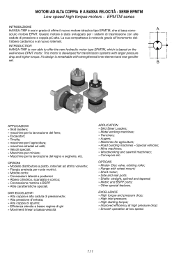
JM-GM-JMM
MANUALE USO E MANUTENZIONE
OPERATING MANUAL
SERIE JM-GM-JMM
JM-GM-JMM SERIES
MOTORI ELETTRICI TRIFASI
ASYNCHRONOUS ELECTRIC MOTORS
JM 56 ... 160
JMM 56 ... 100
1.
GM 160 ... 450
AVVERTENZE GENERALI ...................................................... 2
1.
GENERAL RECOMMENDATIONS ..................................... 2
1.1. Avvertenze sulla sicurezza .............................................................. 2
1.2. Ricevimento ....................................................................................... 2
1.3. Avvertenze sull’installazione ............................................................ 2
1.1. Safety warning ................................................................................... 2
1.2. On receipt ......................................................................................... 2
1.3. Caution during assembling .............................................................. 2
2.
CARATTERISTICHE ............................................................... 3
2.
SPECIFICATIONS ................................................................ 3
2.1.
2.2.
2.3.
2.4.
2.5.
2.6.
2.7.
2.8.
Caratteristiche generali .....................................................................
Identificazione motore .......................................................................
Targa ..................................................................................................
Caratteristiche generali di funzionamento ........................................
Potenza resa in funzione della temperatura ambiente .....................
Potenza resa in funzione dell’altitudine .............................................
Alimentazione motore trifase diversa dai valori nominali .................
Forme costruttive e posizioni di montaggio ......................................
2.1.
2.2.
2.3.
2.4.
2.5.
2.6.
2.7.
2.8.
General specifications ..................................................................... 3
Motor identification ........................................................................... 3
Name plate ........................................................................................ 3
Ratings .............................................................................................. 4
Output power depending on ambient temperature .......................... 4
Output power depending on altitude ................................................ 4
Three-phase motor power supplies differing from the rated values4
Structure and assembly positions ................................................... 5
3.
INSTALLAZIONE ................................................................... 5
3.
INSTALLATION. .................................................................... 5
3
3
3
4
4
4
4
5
3.1. Collegamento motore ......................................................................... 5
3.2. Collegamento accessori .................................................................... 6
3.3. Coppie di serraggio ........................................................................... 7
3.1. Motor connection .............................................................................. 5
3.2. Connection of accessories .............................................................. 6
3.3. Tightening torques ............................................................................ 7
4.
4.
MANUTENZIONE ................................................................... 7
MAINTENANCE ................................................................... 7
4.1. Manutenzione periodica .................................................................... 7
4.2. Lubrificazione cuscinetti ................................................................... 8
4.1. Periodical motor maintenance ......................................................... 7
4.2. lubrication of the bearings ............................................................... 8
5.
6.
5.
6.
RICAMBI JM/JMM ................................................................. 9
RICAMBI GM ......................................................................... 9
JM/JMM SPARE PARTS ...................................................... 9
GM SPARE PARTS .............................................................. 9
Avvertenze importanti: tutte le descrizioni e i dati riportati nel se-
Important notice: texts and data of this manual are not binding and we
guente manuale non sono impegnativi e ci riserviamo il diritto di modificali
senza darne preavviso. Per particolari informazioni tecniche si prega di
farne richiesta al nostro ufficio tecnico. La garanzia sul motore acquistato
viene automaticamente a decadere qualora il motore subisca lo smontaggio
e la sostituzione di parti.
reserve the right to change them without previous notice. For any further
technical information please do not hesitate to contact our technical dept .
Disassembly of the motor or replacement of its parts automatically voids the
warranty on the purchased motor.
Ricordiamo che i motori del presente manuale sono conformi alle seguenti Direttive Comunitarie:
Please note that the motors in this manual comply with the following
Community Directives:
- Direttiva “Bassa Tensione” 2006/95/CEE. I motori del presente manuale sono conformi alla direttiva e riportano in targa il marchio CE.
- “Low Voltage” directive 2006/95/CEE. The motors of this manual
comply with the requirements of the directives and show on the nameplate
CE brand.
- Direttiva “Compatibilità Elettromagnetica” 2004/108/CEE. Non obbligatoriamente applicabile ai prodotti di questo manuale. La responsabilità della conformità alla direttiva è a carico del costruttore della macchina.
- “Electromagnetic Compatibility” directive 2004/108/CEE. Not
compulsory on the products of this manual. Compliance to the directive
is responsibility of the builder of the machine.
Ricordiamo inoltre che il motore elettrico è un componente che non deve
essere posto in servizio prima di essere installato in una macchina (o
sistema completo) resa e dichiarata conforme alle disposizioni della “Direttiva Macchine” 2006/42/CEE.
We remind that: electric motors are components which shall not be started
for duty unless installed on a machine (or complete system) which must
comply and must be declared to comply with the “Machine directive” 2006/
42/CEE.
rev. 00
P. 1
JM-GM-JMM
1.
AVVERTENZE GENERALI
1.1. Avvertenze sulla sicurezza
1.
GENERAL RECOMMENDATIONS
1.1. Safety warning
Un uso improprio del motore, un’installazione non corretta, la
Improper use of the motor, incorrect installation, removal of
rimozione delle protezioni, l’eliminazione dei dispositivi di sicurezza,
la carenza di manutenzione, possono causare gravi danni a persone e
cose. Pertanto deve essere movimentato, installato, messo in servizio, curato e
riparato esclusivamente da personale qualificato (secondo IEC364).
the protections, elimination of the safety devices and negligent
maintenance may cause serious damage to persons and things.
Thus, the motor must only be handled, installed, commissioned, serviced
and repaired by qualified personnel (in accordance with IEC364).
Pericoli: motori elettrici presentano parti poste sotto tensione, parti in movi-
Dangers: electric motors have under tension parts, moving parts and
mento, parti con temperature superiori a 50°C. Qualsiasi intervento sul motore
deve avvenire sempre quando è fermo e scollegato dalla rete di alimentazione.
Scollegare eventuali equipaggiamenti ausiliari ed eliminare ogni possibilità di avviamento improvviso. Nei motori monofase il condensatore di esercizio può rimanere
carico, mantenendo sotto tensione la morsettiera motore.
parts that reach temperatures exceeding 50°C. Any operation on the motor
must be performed when the motor itself is at a standstill and disconnected
from the mains power supply. Disconnect any auxiliary equipment and
take all measures to prevent sudden starts. The capacitor of single-phase
motors may remain loaded, thus keeping the motor’s terminal box live.
1.2. Ricevimento
1.2. On receipt
Verificare che il motore corrisponda a quanto ordinato e che non abbia
subito danneggiamenti durante il trasporto. Non si può mettere in servizio un
motore danneggiato.
Make sure that the motor is the same as the one ordered and that it has
sustained no damage during transport. A damaged motor cannot be used.
I golfari eventualmente presenti nella carcassa servono al solleva-
If the motor remains in stock, store it in a sheltered, clean, dry place
free from vibrations and corrosive agents. If the motor remained in stock
for a long period, it is advisable to check the insulation resistance
between the windings and towards earth with the relative d.c. instrument
(500V).
mento del solo motore.
Per l’eventuale giacenza in magazzino, il luogo deve essere coperto, pulito, asciutto, privo di vibrazioni e agenti corrosivi. Dopo lunghi periodi
di giacenza a magazzino si consiglia di verificare la resistenza di isolamento tra gli avvolgimenti e verso massa con apposito strumento in corrente continua (500V).
Durante e immediatamente dopo la misura è presente sui morsetti
una tensione pericolosa; i morsetti non devono essere toccati. Per
avvolgimenti nuovi il valore misurato non deve essere inferiore a 10 MΩ con
l’avvolgimento a temperatura di 25°C. Valori inferiori sono normalmente indice di
presenza di umidità negli avvolgimenti, in tal caso vanno essiccati.
The eyebolts on the housing are designed for lifting the motor only.
While the measurement is being taken and immediately
afterwards, some of the terminal carry dangerous voltages and
mustn’t be touched. In case of new winding with a winding temperature of
25°C the value measured mustn’t be lower than 10 MΩ. Lower values
usually denote the presence of humidity in the winding, in this case let them
dry.
1.3. Caution during assembling
1.3. Avvertenze sull’installazione
Per funzionamenti con temperatura diversa da -15 +40 °C e ad
altitudini superiori ai 1.000 m interpellateci. Non è consentito l’impiego in luoghi con atmosfere aggressive, con pericolo di esplosione. Sistemare il motore in modo che si abbia un ampio passaggio d’aria
dal lato della ventola; insufficiente circolazione d’ aria compromette lo scambio
termico. Evitare la vicinanza con altre fonti di calore tali da influenzare la
temperatura sia dell’aria di raffreddamento che del motore per irraggiamento.
Eventuali fori scarico condensa devono essere rivolti verso il basso, per
permettere lo scarico. Quando è possibile proteggere il motore: dall’eccessivo irraggiamento solare (la temperatura del motore potrebbe aumentare
eccessivamente), dalle intemperie (IM V1 e derivate è necessario proteggere il motore con un tettuccio para-pioggia) e da spruzzi d’acqua (sigillare
la scatola morsettiera e l’entrata cavo con mastice da guarnizione).
Fondazione: deve essere ben dimensionata per garantire stabilità al fissaggio. Accoppiamenti: per il foro degli organi calettati sull’estremità dell’albero è consigliata la tolleranza H7; prima di eseguire l’accoppiamento pulire
e lubrificare le superfici di contatto per evitare pericoli di grippaggio. Nelle
operazioni di montaggio (smontaggio) utilizzare sempre appositi tiranti
(estrattori) per evitare eventuali danni ai cuscinetti del motore. L’uso del
martello è quindi da escludere. È consigliabile riscaldare eventuali giunti,
pulegge fino a 60-80°C prima del montaggio. Accoppiamento diretto:
curare l’allineamento del motore rispetto a quello della macchina condotta.
Accoppiamento a cinghia: verificare che l’asse del motore sia sempre
parallelo all’asse della macchina condotta, lo sbalzo della puleggia deve
essere il minimo possibile, la tensione delle cinghie non deve essere eccessiva per non compromettere la durata dei cuscinetti o provocare la rottura
dell’albero motore. I motori sono equilibrati con mezza linguetta; per evitare
vibrazioni e squilibri è necessario che gli organi di trasmissione siano stati
opportunamente equilibrati prima dell’accoppiamento. Per servizi con elevato numero di avviamenti è necessario proteggere il motore per evitare un
surriscaldamento eccessivo, utilizzando una protezione termica; l’interruttore magnetotermico non è sufficiente. Per ottenere avviamenti dolci con
basse correnti di spunto si può adottare l’avviamento a tensione ridotta (per
partenze a vuoto o con carichi ridotti utilizzare l’avviamento Y / ∆ o con soft
starters, mentre per avviamenti a pieno carico e nelle applicazioni con
elevati momenti d’inerzia, utilizzare l’inverter). Funzionamento con
inverter: i motori JM e GM sono adatti al funzionamento con inverter
(valori limiti: tensione alimentazione UN < 500 V, picchi di tensione Umax <
1.000 V, gradienti di tensione dU/dt < 1 kV/µs. Per tensione di alimentazione
> 500 V interpellarci. L’utilizzo dell’inverter richiede delle precauzioni: l’entità
P. 2
Please contact us if the motor must operate at a different temperature from -15 +40 °C or at an altitude of more than 1,000 m. It is
forbidden to use the motor in places with an aggressive
atmosphere, where there is a risk of explosion. The motor must be
positioned so that air is free to pass around the fan side. Insufficient air
circulation will obstruct the heat exchange. Do not install the motor near
other heat sources that could affect the temperature of both the cooling air
and the motor itself. Holes for draining off condensation must point
downwards, so as to allow the fluid to flow out. When possible, protect the
motor against: excessive exposure to the sun (the temperature of the
motor could increase too much), inclement weather (protect the motor with
the rainproof cover when IM V1 and deriving versions are required) and
splashing water (seal the terminal box and cable inlet with sealing cement).
Foundation: must be well-sized to ensure that the assembly is stable.
Couplings: tolerance H7 is recommended for the hole of the parts keyed to
the end of the shaft; clean and lubricate the surfaces before coupling so
as to prevent seizures. Always use the relative jacking screws (pullers)
during the assembly and disassembly operations so as to prevent the
motor bearings from being damaged. Never use a hammer or mallet.
Joints and pulleys should be heated to 60-80°C prior to assembly. Direct
coupling: make sure that the drive shaft is aligned with that of the driven
machine. Belt drives: make sure that the shaft of the motor is parallel to
the shaft of the driven machine, that the pulley overhangs to the smallest
possible extent and that the belt tension is unable to impair the life of the
bearings or break the drive shaft. The motors are balanced with a halfkey. To prevent vibrations or imbalances, the transmission components
must be correctly balanced before they are coupled. For duty with a high
number of starts, the motor must be protected against excessive heating
by means of a thermal protection; a magneto thermal circuit-breaker is
not enough. The low-voltage starting method can be used to obtain smooth
starts at low breakaway starting current values (use Y / ∆ or soft starters
for no load starts or with reduced loads and use an inverter for full-load
starts or applications with high moments of inertia). Operation with
inverters: JM and GM motors are suitable for operation with inverters
(limit values: power-supply voltage UN < 500 V, voltage peaks Umax < 1.000
V, voltage gradients dU/dt < 1 kV/µs. Contact us for > 500 V power supply
voltage values. Use of inverters requires the following precautions: the
entity of these peaks/gradients is bound to the inverter’s power-supply
voltage and the length of the motor’s feeder cables. To limit this entity, it is
advisable to use special filters (at the purchaser’s charge) installed
between the inverter and motor (obligatory for > 30 m feeder cables).
rev. 00
JM-GM-JMM
di tali picchi/gradienti è legata al valore della tensione di alimentazione
dell’inverter e alla lunghezza dei cavi di alimentazione del motore. Per limitare tale entità si consiglia l’utilizzo di appositi filtri (a cura dell’acquirente)
posti tra inverter e motore (obbligatori per cavi di alimentazione > di 30 m).
Motori ATEX 94/9/CE gruppo II categoria 3D per zona 22: l’acquirente del prodotto avrà la responsabilità di adottare opportune misure
tecniche ed organizzative e di valutare ogni possibile rischio d’esplosione
per la salute e sicurezza dei lavoratori in aree potenzialmente esplosive
(Direttiva 99/92/CE). Al ricevimento del motore elettrico accertarsi che non
presenti danni o anomalie. Prima di mettere in funzione il motore controllare
i dati riportati in targa, leggere attentamente il manuale di istruzioni (in dotazione al motore) e verificare la sua idoneità alla applicazione richiesta. Nel
caso di applicazioni con inverter interpellarci.
2.
CARATTERISTICHE
2.1. Caratteristiche generali
Serie J M / G M / JMM
JM: IEC 56...160; 0,09...18.5 kW; 2,4,6,8 poli trifase
GM: IEC 160...450; 4...900 kW; 2,4,6,8 poli trifase
JMM: IEC 56...100; 0,09...2.2 kW; 2,4 poli monofase
Motore elettrico asincrono trifase normalizzato per uso generale in
applicazioni industriali, con rotore a gabbia in corto circuito, chiuso, autoventilato
esternamente (metodo di raffreddamento IC 411), classe termica d’isolamento F
(sovratemperatura motore classe B per tutti i motori con potenza normalizzata;
classe B o B/F per i rimanenti motori trifasi e monofasi). Progettato per operare in
servizio continuo (S1) a tensione e frequenza nominali.
I motori JM e GM sono adatti al funzionamento con inverter.
Non è consentito l’impiego in luoghi con atmosfere aggressive e con
ATEX 94/9/EC group II class 3D motors for zone 22: the purchaser
is responsible for taking adequate technical and organizational measures
and for assessing all possible explosion hazards so as to protect the
health and safety of workers in potentially explosive areas (Directive 99/
92/EC). As soon as the motor arrives, check to make sure that it is not
faulty or damaged in any way. Before operating the motor, check the plate
data, read carefully the instruction manual (supplied with the motor) and
make sure that the motor is suitable for the required use. Please contact
us if the application will be used with an inverter.
2.
SPECIFICATIONS
2.1. General specifications
J M / G M / JMM series
JM: IEC 56...160; 0.09...18.5 kW; 2,4,6,8 poles three-phase
GM: IEC 160...450; 4...900 kW; 2,4,6,8 poles three-phase
JMM: IEC 56...100; 0.09...2.2 kW; 2,4 poles single-phase
Standard asynchronous three-phase electric motor with shortcircuited squirrel-cage rotor for general purposes in industrial
applications; enclosed, externally fan-cooled (with IC 411 cooling
method), thermal insulation class F (class B motor over temperature
class with standard power; class B or B/F for the remaining three-phase
and single-phase motors). Motor designed for continuous duty (S1) at
rated voltage and frequency.
JM and GM motors are suitable for operation with inverters.
It is forbidden to use the motor in places with an aggressive
atmosphere and where there is a risk of explosion.
pericolo di esplosione.
2.2. Identificazione motore
2.2. Motor identification
Tab. 2.1 / Tab. 2.1
2.3. Targa
2.3. Name plate
Fig. 2.1 / Draw. 2.1
1)
2)
3)
4)
5)
6)
7)
8)
9)
10)
11)
12)
13)
14)
15)
16)
17)
Mese e anno di costruzione (eventuale numero di matricola)
Eventuale classe di efficienza
Numero delle fasi
Tipo motore/grandezza/numero poli/designazione forma costruttiva
Massa del motore (solo se > di 30kg)
Classe di isolamento
Grado di protezione
Servizio
Capacità condensatore (serie JMM)
Eventuali esecuzioni speciali
Collegamento delle fasi
Tensione nominale
Frequenza nominale
Corrente nominale
Potenza nominale
Velocità nominale
Fattore di potenza
rev. 00
1)
2)
3)
4)
5)
6)
7)
8)
9)
10)
11)
12)
13)
14)
15)
16)
17)
Month and year of manufacture (and serial number if possible)
Efficiency class if possible
Number of phases
Type of motor/size/number of poles/designation/mounting type
Weight of motor (only if > 30kg)
Insulation class
Protection class
Duty
Capacitor capacitance (JMM series)
Special mounting types, if applicable
Phase connection
Voltage rating
Rated frequency
Current rating
Rated power
Rated speed
Power factor
P. 3
JM-GM-JMM
2.4. Caratteristiche generali di funzionamento
2.4. Ratings
-
-
servizio continuo - S1
temperatura aria ambiente: - 15 °C ÷ + 40 °C
altitudine massima pari a 1.000 m s.l.m.
alimentazione a tensione e frequenza nominali, variazione massima di
tensione ammessa ± 5%. Per i limiti massimo e minimo di alimentazione,
considerare un ulteriore ± 5% ( es. un motore a 230/400 V è idoneo per
tensioni nominali di rete fino a 220/380 V e 240/415 V). Consultare anche
Tab. 2.4 e relative note.
2.5. Potenza resa in funzione della temperatura ambiente
continuous duty - S1
ambient air temperature: - 15 °C to + 40 °C
maximum altitude: 1000 m above sea level
power supply at the rated voltage and frequency values, tolerated
maximum voltage variation ± 5%. Consider a further ± 5% for the
maximum and minimum power supply limits (e.g. a 230/400 V motor is
suitable for mains voltage values up to 220/380 V and 240/415 V). Also
consult Tab. 2.4 and the relative notes.
2.5. Output power depending on ambient temperature
Tab. 2.2 / Tab. 2.2
2.6. Potenza resa in funzione dell’altitudine
2.6. Output power depending on altitude
Tab. 2.3 / Tab. 2.3
2.7. Alimentazione motore trifase diversa dai valori nominali
(per tensioni o frequenze speciali contattarci)
Attenzione: il rendimento di un motore può diminuire quando viene
alimentato a valori di tensione/frequenza diversi da quelli nominali.
2.7. Three-phase motor power supplies differing from the
rated values (please contact us if special voltage or
frequency values are required)
Important: the efficiency of a motor may drop if it is powered with
different voltage/frequency values from the rated ones.
Tab. 2.4 / Tab. 2.4
1)
2)
P. 4
Tensione d’alimentazione sconsigliata per impieghi gravosi e funzionamento prolungato del motore. Il motore può funzionare con tale
alimentazione ma non si devono avere avviamenti a pieno carico; la
potenza richiesta non deve superare il valore nominale. La
sovratemperatura del motore può risultare maggiore.
Il motore può funzionare con tale alimentazione ma non si devono
avere avviamenti a pieno carico.
1)
2)
Power supply voltage not recommended if the motor is subjected to
heavy duty use or long periods of continuous duty. The motor can
function with this type of power supply, but must not be started at full
load. The power demand must not exceed the rated value. The motor’s
over temperature may be higher.
The motor can function with this type of power supply, but must not
be started at full load.
rev. 00
JM-GM-JMM
2.8. Forme costruttive e posizioni di montaggio
2.8. STRUCTURE AND ASSEMBLY POSITIONS
Le forme costruttive previste sono IM B3, IM B5, IM B14 e forme combinate
IM B35 (B3/B5) e IM B34 (B3/B14). I motori possono funzionare anche
nelle corrispondenti forme costruttive ad asse verticale. Le forme costruttive
e le posizioni di montaggio sono riportate in tabella (Tab. 2.5). Nella serie JM
56…160 e JMM 63…100 è possibile montare i piedi sui tre lati della carcassa, al fine di avere la scatola morsettiera sul lato desiderato (avvitare
correttamente i bulloni di fissaggio).
The versions available are IM B3, IM B5, IM B14 and combined structures
IM B35 (B3/B5) and IM B34 (B3/B14). The motors can also function in the
corresponding vertical shaft configurations. The mounting types and
assembly positions are given in the table (Tab. 2.5). On JM series JM56
...160 and JMM 63...100 it is possible to mount the feet on the three
sided of the casing, this allows to put the terminal box on the desired side
( tighten properly the screw).
Tab. 2.5 / Tab. 2.5
1)
2)
3)
3.
Possibile
Consultare seipee motori
Motori con piedi
Motori con flangia: fori passanti
Motori con flangia: fori filettati
INSTALLAZIONE
1)
2)
3)
3.
Possible
Consult seipee motors
Motors with stands
Motors with flange: through holes
Motors with flange: threaded holes
INSTALLATION.
3.1. Collegamento motore
3.1. Motor connection
Prima di effettuare l’allacciamento elettrico assicurarsi che l’alimentazione corrisponda ai dati elettrici riportati in targa. Eseguire il collegamento
secondo gli schemi indicati nel foglio contenuto all’interno della scatola
morsettiera. Utilizzare cavi di sezione adeguata in modo da evitare un
surriscaldamento e/o eccessiva caduta di tensione ai morsetti del motore.
Make sure that the power supply voltage corresponds to the electrical
data on the data plate before making the electrical connections. Make the
connections as indicated in the wiring diagrams on the sheet inside the
terminal box. Use cables with adequate sections to prevent overheating or
excessive voltage drops on the motor’s terminals.
Motore trifase: fare attenzione al collegamento esistente in morsettiera e
a quello riportato sulla targa del motore; il voltaggio minimo è riferito al
collegamento a ∆, il voltaggio massimo a Y. L’avviamento stella-triangolo è
possibile solo quando la tensione di rete corrisponde al valore a ∆.
Senso di rotazione: è consigliabile verificare il senso di rotazione del
motore prima dell’accoppiamento alla macchina utilizzatrice, quando un senso
di rotazione contrario a quello desiderato può causare danni a persone e/o
cose (si consiglia di togliere la linguetta dall’estremità dell’albero per evitare
la sua violenta fuoriuscita). Per modificare il senso di rotazione nei motori
trifase è sufficiente invertire due fasi di alimentazioni della linea, mentre per
i motori monofase occorre cambiare la disposizione dei ponticelli presenti in
morsettiera (seguire lo schema di collegamento presente sul lato interno del
coprimorsettiera).
Messa a terra: le parti metalliche del motore che normalmente non sono
sotto tensione devono essere collegate a terra utilizzando l’apposito morsetto
contrassegnato, posto all’interno della scatola morsettiera (utilizzare un
cavo di sezione adeguata).
rev. 00
Three-phase motor: pay attention to the connection in the terminal box
and to the one shown on the motor’s data plate. The minimum voltage
refers to the ∆ connection, the maximum voltage to the Y connection. Stardelta starting can only be obtained when the mains voltage corresponds to
the value of ∆.
Direction of rotation: it is advisable to check the motor’s direction of
rotation before it is coupled to the user machine. The wrong direction of
rotation could cause damage to persons and things (you are advised to
remove the spline from the end of the shaft to prevent it from springing out
in a violent manner). To change the direction of rotation of a three-phase
motor, just switch two of the mains power phases while in single-phase
motors, you must change the positions of the jumpers in the terminal box
(comply with the wiring diagram inside the terminal box cover).
Earth connection: metal parts of the motor that are normally not live
must be earthed by means of the relative terminal in the terminal box (use
a cable with an adequate section).
P. 5
JM-GM-JMM
Schema di collegamento trifase singola polarità
Three-phase single polarity wiring diagram
Schema di collegamento monofase
Single-phase wiring diagram
Fig. 2.1 / Draw. 2.1
3.2. Collegamento accessori
3.2. Connection of accessories
Collegamento protezione termiche
Terminali posti all’interno della scatola morsettiera motore. Le protezioni
necessitano di un apposito relè o apparecchiatura di sgancio (a carico
dell’acquirente del motore). Prima del collegamento, verificare le caratteristiche riportate nella targhetta adesiva che identifica il tipo di protezione.
ATTENZIONE: il mancato collegamento delle sonde termiche
(quando presenti) comporta l’annullamento della garanzia del
motore.
Connection of thermal protections
Terminals installed inside the motor’s terminal box. These protections
require a dedicated relay or release device (at the motor purchaser’s
charge). Check the specifications on the sticker that identifies the type of
protection prior to connection.
WARNING: failure to connect the thermal probes (when
applicable) will void the warranty with which the motor is provided.
Collegamento sensore di temperatura PT 100 (termometro a resistenza). Conformi alle norme DIN-IEC 751. Prima del collegamento verificare
le caratteristiche riportate sella targhetta adesiva che identifica il tipo di
protezione. I PT 100 necessitano di una apposita apparecchiatura per essere utilizzati (a carico dell’acquirente del motore).
Avvolgimento: tre PT 100 inseriti nell’avvolgimento uno per fase. Terminali
posti all’interno della scatola morsettiera motore.
Cuscinetti: un PT 100 inserito nel supporto cuscinetto (lato comando, lato
opposto comando). Terminali posti all’interno di una scatola di derivazione
solidale alla carcassa del motore.
Collegamento scaldiglia anticondensa
Terminali posti all’interno della scatola morsettiera motore. Prima del collegamento verificare le caratteristiche riportate sulla targhetta adesiva che identifica il tipo di protezione (verificare i dati di alimentazione). La scaldiglia non
deve essere alimentata durante il funzionamento del motore.
Collegamento servoventilatore assiale
Terminali di alimentazione posti all’interno di una scatola morsettiera ausiliaria solidale al copriventola. Prima del collegamento verificare le caratteristiche riportate sulla targhetta adesiva di identificazione (verificare i dati di
alimentazione).
Importante: verificare che il senso di rotazione del ventilatore trifase
corrisponda a quello indicato dalla freccia posta sul copriventola; in caso
contrario invertire due delle tre fasi di alimentazione.
Collegamento encoder
Cavetto di collegamento munito di connettore maschio di tipo militare fissato
al motore. Viene fornito anche il connettore femmina con relativo schema
per il collegamento). Prima del collegamento verificare le caratteristiche
riportate sulla targhetta adesiva di identificazione.
Consigli utili all’installazione.
- utilizzare cavi schermati con connessione a terra; devono essere posizionati separatamente dai cavi di potenza
- Installare la scheda di controllo il più vicino possibile all’encoder e il più
lontano possibile all’eventuale inverter (quando non è possibile schermare in modo adeguato l’inverter).
P. 6
PT 100 temperature sensor connection(resistance thermometer).
Comply of standard DIN-IEC 751. Check the specifications on the sticker
that identifies the type of protection prior to connection. PT 100 sensors
require a special device in order to be used (at the motor purchaser’s
charge).
Winding: three PT 100 installed in the winding, one per phase. Terminals
installed inside the motor’s terminal box.
Bearings: a PT 100 installed in the bearing support (control side, side
opposite control). Terminals installed inside a switch box enbloc with the
motor housing.
Connection of the anti-condensation heater
Terminals installed inside the motor ’s terminal box. Check the
specifications on the sticker that identifies the type of protection prior to
connection (check the power supply specifications). The heater must not
be powered while the motor is running.
Connection of the forced axial fan
The powering terminals are installed in an auxiliary terminal box on the
fan cover. Check the specifications on the identification sticker prior to
connection (check the power supply specifications).
Important: make sure that the direction in which the three-phase fan
spins corresponds to the direction indicated by the arrow on the fan cover.
Switch two of the three power phases if this is not the case.
Encoder connection
Connection lead equipped with a military type male connector fixed to the
motor. The female connector and the relative wiring diagram are also
supplied). Check the specifications on the identification sticker prior to
connection.
Recommendations for installation.
- use shielded cables with earth connection; they must be routed separately
from the power cables
- install the control board as near as possible to the encoder and as far
as possible from the inverter (when the inverter cannot be shielded in an
adequate way).
rev. 00
JM-GM-JMM
Importante: al termine dei collegamenti, verificare il corretto serraggio
dei morsetti elettrici, posizionare correttamente la guarnizione e richiudere
la scatola morsettiera. Per installazioni in ambienti con frequenti spruzzi
d’acqua si consiglia di sigillare la scatola morsettiera e l’entrata cavi con
mastice per guarnizioni.
Important: once the connections have been made, check to make
sure that the electric terminals are well tightened, position the seal correctly
and close the terminal box again. If the motor is installed in a place where
it is frequently subjected to splashing water, it is advisable to seal the
terminal box and cable inlet with sealing cement.
3.3. Coppie di serraggio
3.3. Tightening torques
Tab. 3.1 / Tab. 3.1
1)
2)
4.
Coppia di serraggio dadi esagonali morsettiera motore (collegamento
elettrico)
Coppia di serraggio bulloni fissaggio componenti motore (scudi, flange,
piedi,scatola morsettiera,copri ventola,morsetto di terra)
1)
MANUTENZIONE
4.
2)
Tightening torque hexagonal nuts terminal block (electrical
connection).
Tightening torque fixing screws of the motor parts (shields, flanges,
feet, terminal box, fan cover, earth terminal).
MAINTENANCE
4.1. Manutenzione periodica
4.1. Periodical motor maintenance
Da effettuarsi in condizioni di totale sicurezza: motore fermo, scollegato
dalla rete di alimentazione.
To be carried out in conditions of total safety: motor at a standstill and
disconnected from the mains power supply.
- Verificare che l’intero circuito di raffreddamento (carcassa, entrata d’aria dal lato ventola, eventuale servoventilatore) sia esente da polvere, oli e da qualsiasi residuo di lavorazione in modo da evitare che il motore
si surriscaldi per l’impedimento del normale ciclo di raffreddamento.
- Make sure that the entire cooling circuit (housing, air inlet from the
fan side and forced ventilation fan, if applicable) is free from dust, oil
and any machining residue so as to prevent the motor from overheating
and the normal cooling cycle from being impaired.
- Controllare che il motore funzioni senza vibrazioni né rumori
anomali. Se ci sono vibrazioni controllare la fondazione del motore e
l’equilibratura della macchina accoppiata.
- Make sure that the motor operates without vibrations or abnormal
noise. If vibrations are noted, check the motor’s foundation and make
sure that the machine to which the motor is connected is correctly
balanced.
- Verificare la tensione di eventuali cinghie (una tensione elevata
riduce sensibilmente la durata dei cuscinetti del motore, può causare
anche la rottura dell’estremità dell’albero).
- Check the tension of any belts (excessively taut belts sensibly reduce the life of the motor’s bearings and can cause the shaft end to break).
- Verificare lo stato delle tenute sull’albero ed ingrassarle periodicamente perché tali componenti lavorano a contatto con le parti in movimento e si usurano velocemente. Una volta usurate , vanno sostituite utilizzando componenti identici agli originali.
- Check the condition of the shaft seals and grease them periodically
as these components function in contact with moving parts and wear out
very quickly. Once worn, they must be replaced with components identical
to the original ones.
- Verificare lo stato dei cuscinetti
I cuscinetti montati nella serie JM e JMM vanno semplicemente sostituiti al
termine della loro vita. I cuscinetti montati nelle serie GM necessitano di
lubrificazione ad intervalli regolari (vedere etichetta sugli intervalli posta
sul motore). La durata dei cuscinetti varia molto a seconda dei tipi di
carichi e di avviamenti che si applicano al motore e dipende anche dalle
temperature e dall’umidità dell’ambiente di lavoro. L’eccessiva rumorosità
indica di solito la necessità di sostituire i cuscinetti. Se la messa in funzione è stata realizzata da poco occorre innanzi tutto controllare l’accoppiamento (provvedere a correggere gli errori di allineamento o verificare la
tensione delle eventuali cinghie). Se i cuscinetti continuano ad essere
rumorosi, significa che sono già stati compromessi e occorre sostituirli.
Durante la sostituzione dei cuscinetti, quando si estrae l’albero con rotore
dallo statore, occorre fare molta attenzione a non danneggiare gli
avvolgimenti. Per il montaggio dei cuscinetti utilizzare una pressa con
adeguato manicotto appoggiato all’anello interno, oppure preriscaldare il
cuscinetto stesso a circa 80 °C e porlo in sede. Assicurarsi che gli anelli
interni siano correttamente appoggiati agli spallamenti dell’albero e che i
cuscinetti sostituiti siano dello stesso tipo o equivalenti a quelli originali. Si
consiglia di sostituire sempre le tenute sull’albero.
- Check the condition of the bearings
The bearings installed in the JM and JMM series must be simply
replaced at the end of their working life. The bearings installed in the
GM series need to be lubricated at regular intervals (the frequency is
indicated on the label on the motor). Bearing life varies considerably
and depends on the type of load and number of starts to which the motor
is subjected. It also depends on the temperature and degree of humidity
in the work environment. Excessive noise usually means that the bearings
need to be replaced. If the motor has been recently commissioned, the
first thing to do is to check the coupling (correct any alignment errors
and check the tension of any belts). If the bearings continue to be noisy
it means that they are already damaged and must be replaced. Take
great care to prevent the windings from being damaged when the bearings
are being replaced and the shaft with rotor is removed from the stator.
Use a press with an adequate sleeve resting on the inner ring when
assembling the bearings, or preheat the bearing to a temperature of
about 80°C and place it in its housing. Make sure that the inner rings
rest correctly against the shaft supports and that the replaced bearings
are the same as the original ones or an equivalent type. It is always
advisable to replace the seals on the shaft.
rev. 00
P. 7
JM-GM-JMM
4.2. Lubrificazione cuscinetti
4.2. lubrication of the bearings
Procedimenti per la rilubrificazione dei cuscinetti non schermati:
- Se l’intervallo di rilubrificazione è inferiore ai sei mesi (periodo indicativo),
tutto il grasso esistente va comunque sostituito completamente al massimo dopo 2÷3 rabbocchi.
- Se l’intervallo di rilubrificazione è superiore ai sei mesi (periodo indicativo), tutto il grasso va sostituito ogni sei mesi.
Procedure for re-lubricating non-shielded bearings:
- If the bearings must be re-lubricated at intervals of less than once every
six months (indicative frequency), all the grease must still be completely
replaced after 2 or 3 top-ups at most.
- If the bearings must be re-lubricated at intervals of more than once
every six months (indicative frequency), all the grease must be
completely replaced every six months.
Per sostituire completamente il grasso usato, se i supporti sono
accessibili, è consigliabile rimuovere il grasso esistente e rilubrificare il
cuscinetto manualmente. Lo spazio libero all’interno del cuscinetto va riempito tutto con grasso fresco, mentre lo spazio nel supporto va riempito per
il 30 ÷ 50 %. La quantità di grasso nello spazio attorno al cuscinetto non
deve essere eccessiva per non causare un innalzamento locale della temperatura che sarebbe dannoso sia per il grasso sia per il cuscinetto (attenzione a non introdurre impurità nel cuscinetto o nel supporto). Se i supporti
non sono accessibili è possibile sostituire completamente il grasso per
mezzo dell’ingrassatore. Si svita il tappo di scarico (posizionato nella parte
inferiore del supporto) e si esegue il rabbocco affinché tutto il grasso
esausto sia uscito dallo scarico. Quando è possibile eseguire il rabbocco
con il motore in rotazione. Operazione da effettuare sempre in condizioni di
sicurezza, per evitare di immettere all’interno del supporto una quantità
eccessiva di grasso. Una volta raggiunta la temperatura di equilibrio, si
avvita il tappo di scarico. Con intervalli di lubrificazione molto frequenti,
consigliamo di applicare sistemi automatici che semplificano molto l’operazione. La lubrificazione regolare è necessaria alla vita dei cuscinetti e
quindi al funzionamento del motore stesso.
Si raccomanda l’uso di grasso al Litio con base olio minerale di
buona qualità.
When the old grease is replaced, it is advisable to remove all the old
grease and to re-lubricate the bearing by hand if the supports are
accessible. The vacant space inside the bearing must be completely
filled with fresh grease, while only 30 to 50% of the space in the support
must be filled. There must not be too much grease in the space around the
bearing as this could lead to a local temperature increase, which would
ruin both the grease and the bearing (take care to prevent dirt from being
introduced into the bearing or support along with the grease). If the supports
are inaccessible, the grease can be completely replaced by means of the
lubricator. Unscrew the drain plug (in the lower part of the support) and top
up until all the old grease has been pushed out. When possible, top up the
grease whilst the motor is running. This operation must always be carried
out in safe conditions, to prevent the support from being filled with too
much grease. The fill plug can be tightened on once a balanced temperature has been obtained. It is advisable to install automatic systems to
simplify the operation if the bearings must be lubricated very frequently.
Regular lubrication is essential for bearing life and, thus, for the operation
of the motor itself.
Always use good quality mineral oil based Lithium grease.
Tab. 4.1 / Tab. 4.1
*
1)
Dimezzare la quantità di grasso lato opposto accoppiamento.
Valido per grassi al litio di buona qualità e temperature di lavoro non
superiori a 90 °C, albero-motore orizzontale e carichi normali. Dimezzare i valori di tabella per applicazioni con albero-motore verticale. Per
temperature di lavoro superiori ai 90 °C: dimezzare i valori di tabella
per ogni 15 °C di aumento di temperatura. (Temperatura massima di
lavoro, relativa a grasso al Litio con olio di base minerale, pari a circa
110 °C).
Importante: in caso di smontaggio e rimontaggio di componenti del
motore ove sia presente mastice e/o silicone di protezione, garantire lo
stesso livello di protezione al momento del ri-assemblaggio.
P. 8
*
1)
Halve the quantity of grease on the side opposite the coupling.
Valid for good quality lithium grease and operating temperatures of
not more than 90 °C, horizontal drive shaft and normal loads. Halve
the values in the table for applications with a vertical drive shaft. If the
operating temperature exceeds 90°C: halve the values in the table for
every 15°C of temperature increase. (Maximum operating temperature with regard to Lithium grease with mineral based oil, i.e. about
100°C).
Important: if motor components are disassembled or re-assembled
in places where protective cement or silicone has been applied, remember
to guarantee the same degree of protection when the parts are reassembled.
rev. 00
JM-GM-JMM
5.
1)
2)
3)
4)
5)
6)
7)
8)
9)
10)
11)
12)
13)
14)
15)
16)
17)
18)
19)
20)
21)
22)
23)
24)
25)
26)
27)
28)
29)
30)
31)
32)
33)
RICAMBI JM/JMM
Linguetta
V-ring
Tirante per IMB3
Guarnizione coperchio scatola morsettiera
Vite fissaggio morsettiera
Vite fissaggio coprimorsettiera
Coprimorsettiera
Pressacavo
Morsettiera
Vite fissaggio scatola morsettiera
Scatola morsettiera
Statore
Scudo lato opposto comando
Guarnizione scatola morsettiera
Anello di sollevamento
Molla di precarico
Ventola
Anello di tenuta
Tirante per IMB5
Tirante per IMB14
Flangia IMB14
Flangia IMB5
Anello elastico di sicurezza
Copriventola
Cuscinetto
Vite fissaggio copriventola
Rotore
Vite fissaggio piede per IMB3
Carcassa
Piede per IMB3
Scudo lato comando per IMB3
Albero
Condensatore
5. JM/JMM SPARES
JM 56
JM 90 ... 160
1)
2)
3)
4)
5)
Key
V-ring
Jacking screw for IMB3
Terminal box cover seal
Terminal box fastening screw
6)
7)
8)
9)
10)
11)
12
13)
14)
15)
16)
17)
18)
19)
20)
21)
22)
23)
24)
25)
26)
27)
28)
29)
30)
31)
32)
33)
Terminal box cover fastening
screw
Terminal box cover
Cable gland
Terminal box
Terminal box fastening screw
Terminal box
Stator
Shield on side opposite control
Terminal box seal
Lifting ring
Preload spring
Fan
Retention ring
Jacking screw for IMB5
Jacking screw for IMB14
IMB14 flange
IMB5 flange
Safety spring ring
Fan cover
Bearings
Fan cover fastening screw
Rotor
Stand fastening screw for IMB3
Housing
Stand for IMB3
Shield on control side for IMB3
Shaft
Capacitor
Fig. 5.1 / Draw. 5.1
6.
1)
2)
3)
4)
5)
6)
7)
8)
9)
10)
11)
12
13)
14)
15)
16)
17)
18)
19)
20)
21)
22)
23)
24)
25)
26)
27)
28)
29)
30)
31)
32)
33)
34)
35)
36)
37)
38)
39)
40)
41)
42)
RICAMBI GM
Linguetta
Condotto lubrificazione lato comando
Ingrassatore
Scatola morsettiera
Guarnizione scatola morsettiera
Vite fissaggio coprimorsettiera
Pressacavo
Vite fissaggio morsettiera
Morsettiera
Coprimorsettiera
Guarnizione coprimorsettiera
Vite fissaggio scatola morsettiera
Rotore
Golfare
Statore
Scudo lato opposto comando
Tappo
Condotto lubrificazione lato opposto comando
Ventola
Condotto lubrificazione lato comando IMB5
Flangia interna bloccaggio cuscinetto lato opposto comando
Flangia esterna bloccaggio cuscinetto lato opposto comando
Anello elastico di sicurezza
Linguetta bloccaggio ventola
Anello di tenuta
Anello elastico di sicurezza
Cuscinetto lato opposto comando
Flangia esterna bloccaggio cuscinetto lato comando
Flangia interna bloccaggio cuscinetto lato comando
Cuscinetto lato comando
Anello elastico di sicurezza
Molla di precarico GM160...355
Flangia IMB5
Copriventola
Vite fissaggio copriventola
Morsetto di terra esterno GM315...450
Carcassa
Scudo lato comando IMB3
Vite fissaggio scudo IMB3 lato comando
Tappo scarico lubrificante
Vite fissaggio flangia esterna bloccaggio cuscinetto
Albero
rev. 00
6.
1)
2)
3)
4)
5)
6)
7)
8)
9)
GM SPARES
Key
Lubrication duct on control side
Lubricator
Terminal box
Terminal box seal
Terminal box cover fastening screw
Cable gland
Terminal box fastening screw
Terminal box
10)
11)
12 )
13)
14)
15)
16)
17)
18)
19)
20)
21)
22)
Fig. 5.2 / Draw. 5.2
27)
28)
29)
30)
31)
32)
33)
34)
35)
36)
37)
38)
39)
40)
41)
42)
23)
24)
25)
26)
Terminal box cover
Terminal box cover seal
Terminal box fastening screw
Rotor
Eyebolt
Stator
Shield on side opposite control
Plug
Lubrication duct on side
opposite control
Fan
IMB5 lubrication duct on
control side
Internal bearing locking
flange on side opposite
control
External bearing locking
flange on side opposite
control
Safety spring ring
Fan locking key
Retention ring
Safety spring ring
Bearing on side opposite control
External bearing locking flange on control side
Internal bearing locking flange on control side
Bearing on control side
Safety spring ring
GM160...355 preload spring
Flange IMB5
Fan cover
Fan cover fastening screw
GM315...450 external earth terminal
Housing
Shield on control side for IMB3
IMB3 shield fastening screw on control side
Lubricant drain plug
External bearing locking flange fastening screw
Shaft
P. 9
JM-GM-JMM
NOTE:
NOTES:
___________________________________________________________
___________________________________________________________
____________________________________________________________
____________________________________________________________
___________________________________________________________
___________________________________________________________
___________________________________________________________
___________________________________________________________
___________________________________________________________
___________________________________________________________
___________________________________________________________
___________________________________________________________
___________________________________________________________
___________________________________________________________
______________________________________________________________
______________________________________________________________
___________________________________________________________
___________________________________________________________
___________________________________________________________
___________________________________________________________
___________________________________________________________
___________________________________________________________
___________________________________________________________
___________________________________________________________
___________________________________________________________
___________________________________________________________
___________________________________________________________
___________________________________________________________
___________________________________________________________
___________________________________________________________
___________________________________________________________
___________________________________________________________
___________________________________________________________
___________________________________________________________
___________________________________________________________
___________________________________________________________
____________________________________________________________
____________________________________________________________
___________________________________________________________
___________________________________________________________
___________________________________________________________
___________________________________________________________
P. 10
rev. 00
Scaricare