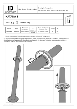
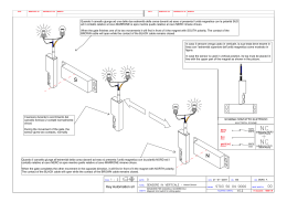
Planetarius
IP20
FOC
0.5m
18-06-2007 Rev.04
ISTRUZIONI MONTAGGIO - ASSEMBLY INSTRUCTIONS
Prima di procedere all'installazione leggere attentamente queste istruzioni. - Carefully read the following instructions before installing the fixture.
E’ obbligatorio sostituire i cavi ogni qualvolta si voglia spostare anche un solo corpo illuminante. - Cables must be replaced if even one lighting fixture is moved.
ITALIANO
ENGLISH
Attenzione:
- L’installazione ed il collaudo di questo apparecchio
devono essere eseguiti esclusivamente da personale
specializzato.
- La casa costruttrice declina ogni responsabilità per i
danni provocati a cose e/o persone dovuti alla mancata osservanza delle presenti istruzioni.
- Rispettare nell’installazione la distanza minima e
massima tra alimentatore e corpo illuminante, max
500mm.
- Prima di procedere all’installazione degli apparecchi
mod. FOCUS-Q fare riferimento al foglio di istruzione
degli accessori Planetarius necessari per la realizzazione del sistema.
- Tutte le operazioni di installazione e manutenzione
devono essere eseguite in assenza di tensione di
rete.
- Utilizzare esclusivamente cavi Mizar S.r.l. modello
“FILUM-D” con portata massima 2500W + 2500W
230V.
- Il Kit è composto da due elementi, l’alimentatore
siglato (A) ed il corpo illuminante siglato (B), vedi
fig. 1.
- Le seguenti operazioni di montaggio vanno eseguite
per entrambi gli elementi (A) e (B), e tesate, rispettando la fase e il neutro della linea di alimentazione.
- Fare molta attenzione nel separare i conduttori.
- Possibilità del sistema di usufruire della doppia
accensione.
Warning:
- The installation and the testing of this instrument must
exclusively be perform from specialized staff.
- Mizar S.r.l. declines all responsibility for any damage
done to people and things, caused by failing to observe
the following instructions or in case of modifications on
sold product.
- Respect in the installation the minimum and maximum
distance between power supply and illuminating body,
max 500mm.
- Before installing Mod. FOCUS-Q fixtures please refer to
the instructions sheet of Planetarius accessories which
are needed to install the system.
- All installation and maintenance operations must be
carried out with mains voltage off.
- Exclusively employ model “FILUM-D” Mizar s.r.l. cables
with maximum capacity 2500W + 2500W 230V.
- The Kit is composed from two elements, the power
supply (A) and the illuminating body (B), fig. 1.
- The following operations of assemblage must be
performed for both the elements (A) and (B), and
flat cable, respecting the phase and the neuter of the
feeding line.
- Particular care should be paid to separating
conductors.
- For this wiring system is possible make the double
switching.
Installazione alimentatore (A):
1. All’interno delle scocche laterali del gruppo di
alimentazione (A) troviamo rispettivamente un
cavo isolato completo di faston (I) che serve per
connettere l’alimentatore elettronico alla linea ed
un secondo cavo isolato con doppio connettore di
lunghezza 500mmm che serve ad alimentare il corpo
illuminante siglato (B).
2. Segnare sul cavo piatto (F) i punti dove si intende
fissare l’alimentatore (A) ed il corpo illuminante (B),
rispettando la distanza minima e massima tra gli
apparecchi, vedi fig. 2.
3. Il cavo di tesata modello “FILUM-D” è composto da
due cavi conduttori + un cavo d’acciaio di sostegno.
Separare con un cutter il cavo di alimentazione (G)
della tesata dagli altri due, vedi fig. 3.
4. Crimpare sul cavo di alimentazione (G) il morsetto
(H) come in fig. 3.
5. Posizionare la base (C) dell’alimentatore (A) e
bloccare il cavo piatto (F) alle estremità con i due
fermacavo (E) fig. 1. Utilizzare il fermacavo lato
lampada per bloccare il cavo di alimentazione del
corpo illuminante.
6. Collegare al morsetto (H) il terminale faston (I) che
fuoriesce dall’alimentatore fig. 3, e posizionare con
cura i due cavi, uno passante relativo alla tesata, e
quello che servirà ad alimentare il corpo illuminante,
all’interno della base in plastica (C) figura 1.
7. Chiudere la base (C) con la copertura (D) fissando
bene le viti. Eventualmente per facilitare la chiusura
della scocca e il passaggio dei cavi attraverso le
ferritoie predisposte, praticare un allargamento
della stesse con un semplice giraviti con lama a
taglio. All’interno della scocca è visibile la porzione
da togliere.
Installazione corpo illuminante (B):
1. All’interno delle scocche laterali del corpo illuminante (B) troviamo un cavo isolato completo di morsetto (L) che serve per connettere il cavo proveniente
dall’alimentatore.
2. Collegare il cavo a doppio connettore (M) al morsetto (L), vedi fig. 1.
3. Posizionare con cura il cavo passante (F) e il cavo (M)
proveniente dall’alimentatore all’interno della base
(C) del corpo illuminante, come nell’ingrandimento
di fig. 1, quindi bloccare il cavo passante alle estremità con i due fermacavo (E) . 1.
Utilizzare
il fermacavo lato alimentatore per bloccare il cavo di
alimentazione del corpo illuminante.
4. Chiudere la base (C) con la copertura (D) fissando
bene le viti. Eventualmente per facilitare la chiusura
della scocca e il passaggio dei cavi attraverso le
ferritoie predisposte, praticare un allargamento
della stesse con un semplice giraviti con lama a
taglio. All’interno della scocca è visibile la porzione
da togliere.
5. Installare la lampada del tipo e potenza indicate
sull’etichetta dell’apparecchio.
Installation of the power supply (A):
1. Inside the side lids (D) of the power supply (A) we
respectively find a isolated cable with the faston (I),
that it needs for connecting the electronic power
supply to the line, and another isolated cable with
double connector of length 500mmm that it needs to
feed the illuminating body (B).
2. To mark on the flat cable (F) the points where he
intends to fix the electronic power supply (A) and the
illuminating body (B), respecting the minimum and
maximum distance, fig.2.
3. The flat cable, model “FILUM-D”, is composed from two
cables conductors + a steel cable of support. Separate
with a cutter the supply cable (G) of the flat cable from
the others two, fig.3.
4. Crimp on the supply cable (G) the clamp (H), fig. 3.
5. Install the base (C) of the power supply (A) and to lock
the flat cable (F) at its end with clip (E), fig.1. To use
the clip (lamp versus) to lock the supply cable of
the illuminating body.
6. Connect the terminal faston (I), which escapes from the
power supply, to the clamp (H), fig.3.
Positioning with care the two cables, the flat cable
of the wiring system and the supply cable of the
illuminating body, inside the base in plastics (C)
figure 1.
7. Close the base (C) with its cover (D) and tightly fasten
screws.
Eventually, to facilitate the passage of the cables
through the predisposed holes, practising a widening
of the same ones with a simple flat bladed screwdriver.
Inside the lid, it is visible the portion to be removed.
Installation illuminating body (B):
1. Inside the side lids of the illuminating body (B) we find
a complete isolated cable of clamp (L) that serves for
connecting the cable coming from power supply.
2. Connect the bipolar cable (M) to the clamp (L), fig.1.
3. Positioning with care the flat cable (F) and the cable
(M), coming from power supply, inside the base (C) of
the illuminating body, as in the enlargement of fig.1,
therefore to lock the flat cable to the extremities with
the two clip (E). .
Using the clip (power supply versus) to lock the
supply cable of the illuminating body.
4. Close the base (C) with its cover (D) and tightly fasten
screws.
Eventually, to facilitate the passage of the cables
through the predisposed holes, practising a widening
of the same ones with a simple flat bladed screwdriver.
Inside the lid, it is visible the portion to be removed.
5. Insert bulb of suitable type and power as shown on the
fixture label.
Legenda - Legend
- Tutti i prodotti di Mizar Srl che rientarno nell’ambito
di applicazione della Direttiva Europea EMC89/336
e 93/68 EEC, soddisfano i requisiti richiesti e recano
la marcatura CE. Il simbolo CE è posto sull’imballo e
nel prodotto.
All the products of Mizar Srl, meet with current
European Directives EMC89/336 and 93/68 EEC,
meet their requirements and are CE marked. The
symbol CE is placed on the packaging and on the
product.
- Doppio Isolamento.Classe II
Class II insulation
IP20
- Protezione contro l’ingresso di corpi solidi
Ø>=12mm.
Protection against solid object Ø>=12mm.
- Apparecchi idonei al montaggio diretto su superfici
infiammabili.
Luminaries suitable for direct mounting on flammable surfaces.
0.5m
- Rispettare la distanza minima dall’oggetto illuminato, misurata lungo l’asse ottico della lampada.
Rispect the minimum distance from lighted object,
measured along the optic axle of the lamp.
- Apparecchiatura elettrica od elettronica, immessa
sul mercato dopo il 13/08/05, soggetta alla Direttiva
2002/96/CE (WEEE).
Electric or electronic equipment, introduced
on the market after 13/08/05, subject to the
Directive 2002/96/CE (WEEE).
Note:
- Le informazioni contenute in questo foglio d’istruzione potranno subire variazioni senza preavviso da parte di Mizar S.r.l.
- In caso di modifiche apportate al prodotto, Mizar S.r.l. declina ogni responsabilità per eventuali danni derivanti dal funzionamento ed installazione dello stesso.
- Nessuna parte di questa pubblicazione può essere modificata, riprodotta, memorizzata in un sistema di archiviazione o trasmessa in qualsiasi forma o con qualsiasi mezzo elettronico, meccanico, di registrazione o altrimenti, senza previa autorizzazione scritta di Mizar S.r.l.
- The contained information in this technical sheet can suffer variations without prior notice from Mizar S.r.l.
- In case of changes performed to the product, Mizar S.r.l. declines every responsibility for possible consequential damages from the operation and installation of the same.
- No part of this publication can be modified, reproduced, memorized in a filing system or transmitted in any form or with any electronic, mechanic device of recording or otherwise, without previous written authorization of Mizar S.r.l.
Part.Nr.
910.220.24.00
Copyright 2007 - Made in Italy
Scaricare