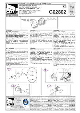
SERIE
GARD | GARD SERIES |
SÊRIE
GARD |
BAUREIHE
LAMPEGGIATORE A CUPOLA
DOME FLASHING LAMP
CLIGNOTANT EN FORME DE COUPOLE
KUPPELBLINKANLAGE
LUZ INTERMITENTE TIPO CÚPULA
MAANVORMIG KNIPPERLICHT
GARD |
SERIE
GARD
Documentazione
Tecnica
T37
G02801
CANCELLI AUTOMATICI
rev. 0.1
06/2004
©
CAME
CANCELLI
AUTOMATICI
119GT37
D
C
B
A
G0280/I-G0281/I
Alimentazione/ Power supply/ Alimentation/ Speisung/ Alimentaciòn/ Voeding
24V
Potenza/ Rated power/ Puissance/ Leistung/ Potencia/ Vermogen
7,5W
Assorbimento/ Input/ Absorption/ Aufnahme/ Absorciòn/ Strromopname
300mA
FRANÇAIS
Clignotant de mouvement en ABS pour
extérieur, installé sur le couvercle de la
barrière avec degré de protection IP54.
ITALIANO
Lampeggiatore di movimento in ABS da
esterno, istallato sulla cupola coperchio
della barriera. con grado di protezione
IP54.
ENGLISH
Exterior-use ABS structure light which
flashes to indicate door movement, installed on the dome-shaped lid of the barrier.
Has IP54 protection.
SCHEMA D’ASSEMBLAGGIO
A- Scheda lampeggiatore
B- Led di segnalazione
C- Morsetti alimentazione
D- Calotta luminosa
ASSEMBLY LAYOUT
A- Flashing lamp board
B- Signalling LED
C- Terminals power supply
D- Flourescent cover
DEUTSCHLAND
Auf der Schrankenabdeckkuppel angebrachte Bewegungsblinkanlage aus ABS für
Außeninstallation mit Schutzgrad IP54.
ESPANOL
Luz intermitente indicadora de movimiento en ABS para exteriores, instalada sobre la tapa de la barrera, con
grado de protección IP54.
NEDERLAND
Uitwendig knipperlicht voor signalering
beweging in ABS, geïnstalleerd op het
koepelvormige deksel van de slagboom.
Met beschermingsklasse IP54.
ESQUEMA DE ENSAMBLAJE
A- Tarjeta luz intermitente
B- Led de señalización
C- Bornes de alimentación
D- Cúpula luminosa
ASSEMBLAGESCHEMA
A- Kaart knipperlicht
B- Led voor signalering
C- Voedingsklemmen
D- Maanvormig knipperlicht
MONTAGEPLAN
A- Karte der Blinkanlage
B- Anzeige LED
C- Speiseklemmen
D- Leuchtkuppel
SCHÉMA D’ASSEMBLAGE
A- Carte clignotant
B- Diode de signalisation
C- Bornes d’alimentation
D- Calotte lumineuse
Pag.1
ITALIANO
PROCEDURA DI MONTAGGIO:
1) Sbloccare il portello d’ ispezione e
liberare il coperchio;
2) Sfondare le impronte all’interno della
cupola coperchio, perpredisporre l’alloggiamento del lampeggiante;
3) Inserire il cavo nel passacavo in dotazione e bloccarlo collegare il cavo in
dotazione (maschio) e infilare la schedina
in senso verticale, sulla guida predisposta
nella cupola gialla;
4) Appoggiare la cupola lampeggiante e
fissarla con le viti UNI 6954 Ø 3,9 x 13.
5) Collegare alla scheda comando il cavo
in dotazione (femmina) nei morsetti 10-E
(ZL38), 10-E7 (ZG5) o 10-E6 (ZG6).
Riposizionare la cupola, richiudere lo
sportello d’ispezione e verificare il funzionamento.
DEUTSCHLAND
MONTAGE:
1) Die Inspektionsklappe entblocken und die
Abdeckung freilegen;
2) Zur Vorbereitung des Blinkersitzes, die
Abdrücke im Inneren der Abdeckkuppel
durchstoßen;
3) Das Kabel in die Kabeldurchführung
einführen und befestigen; das mitgelieferte
Kabel (Stecker) anschließen und die Karte
vertikal in die vorgesehene Führung der
gelben Kuppel einsetzen;
4) Die Kuppel anbringen und mit den Schrauben UNI 6954 Ø 3,9 x 13 befestigen..
5) Das mitgelieferte Kabel (female) auf der
Steuerkarte an den Klemmen 10-E (ZL38),
10-E7 (ZG5) oder 10-E6 (ZG6) befestigen.
Die Kuppel erneut anbringen, die Inspektionsklappe schließen und den Betrieb
überprüfen..
ENGLISH
PROCEDURE:
1) Release the inspection hatch and remove
the lid;
2) Break through the marks under the dome
cover that indicate the holes for mounting the
flashing light;
3) Thread the cable into the fairlead provided
and secure; now connect the cable supplied
(male) and insert the card vertically, onto the
guide in the yellow dome;
4) Lay the flashing dome and fix it with
screws (UNI 6954 Ø 3.9 x 13).
5) Connect the cable supplied (female) to
the command board in the terminals 10-E
(ZL38), 10-E7 (ZG5) or 10-E6 (ZG6).
Reposition the dome, close the inspection
hatch again and check its operation.
FRANÇAIS
PROCÉDURE À SUIVRE :
1) Débloquer le volet d’inspection et
libérer le couvercle ;
2) Enfoncer les empreintes à l’intérieur
du couvercle et préparer le logement du
clignotant ;
3) Introduire le câble dans le serre-câble
fourni de série et le bloquer, brancher le
câble (mâle) et enfiler la carte dans le
sens vertical sur le guide prévu dans la
coupole jaune ;
4) Placer la coupole du clignotant et la
fixer avec les vis UNI 6954 Ø 3,9 x 13.
5) Brancher le câble (femelle) à la carte
de commande à l’aide des bornes 10-E
(ZL38), 10-E7 (ZG5) ou 10-E6 (ZG6).
Remettre la coupole, refermer le volet
d’inspection et vérifier si tout fonctionne
correctement.
ESPANOL
PROCEDIMIENTO:
1) Desbloquee la puerta de inspección y
abra la tapa;
2) Rompa las marcas en el interior de la
tapa para preparar el alojamiento de la
luz intermitente;
3) Introduzca el cable en el prensaestopas suministrado y bloquéelo, conecte el
cable suministrado (macho) e introduzca
la tarjeta en sentido vertical en la guía de
la cúpula amarilla;
4) Apoye la cúpula y fíjela con los tornillos
UNI 6954 Ø 3,9 x 13.
5) Conecte el cable suministrado (hembra) a la tarjeta de mando a los bornes
10-E (ZL38), 10-E7 (ZG5) o 10-E6 (ZG6).
Monte de nuevo la cúpula, cierre la tapa
de inspección y controle el funcionamiento.
NEDERLAND
WERKWIJZE:
1) Deblokkeer het inspectiedeurtje en maak
de deksel los;
2) Doorboor de merktekens aan de binnenkant van de koepelvormige deksel voor
de voorbereiding van de plaatsing van het
knipperlicht;
3) Voeg de kabel in het kabelkanaal van de
uitrusting en blokkeer hem. Sluit de bijgeleverde kabel aan (male) en plaats het kaartje
in verticale richting op de daartoe voorziene
geleider in de gele koepel;
4) Plaats het maanvormig knipperlicht en
maak het vast met de schroeven UNI 6954
Ø 3,9 x 13.
5) Sluit de kabel van de uitrusting aan op de
commandokaart (female) in de klemmen 10E (ZL38), 10-E7 (ZG5) of 10-E6 (ZG6).
Plaats de koepel terug, sluit het inspectiedeurtje en controleer de werking.
1
4
2
1
3
1
3
2
2
2
5
Tutti i dati sono stati controllati con All data checked with the maximum care.
la massima cura. Non ci assumiamo However, no liability is accepted for any
comunque alcuna responsabilità per error or omission.
eventuali errori od omissioni.
ASSISTENZA TECNICA
NUMERO VERDE
800 295830
CANCELLI AUTOMATICI
SISTEMA QUALITÅ
CERTIFICATO
WEB
www.came.it
E-MAIL
[email protected]
CAME CANCELLI AUTOMATICI S.P.A.
DOSSON DI CASIER (TREVISO)
(+39) 0422 4940
(+39) 0422 4941
Toutes les données ont été contrôlées
très soigneusement. Nous n’assumons de
toute façon aucune responsabilité pour les
erreurs ou omissions éventuelles.
Die Daten wurden mit höchster
Sorgfalt geprüft. Für eventuelle Fehler
oder Auslassungen übernehmen wir
keine Haftung.
CAME LOMBARDIA S.R.L._____COLOGNO M. (MI)
(+39) 02 26708293
(+39) 02 25490288
CAME SUD S.R.L. ___________________NAPOLI
(+39) 081 7524455
(+39) 081 7529109
CAME (AMERICA) L.L.C.________MIAMI (FL)
(+1) 305 5938798
(+1) 305 5939823
CAME AUTOMATISMOS S.A__________MADRID
(+34) 091 5285009
(+34) 091 4685442
CAME BELGIUM__________________LESSINES
(+32) 068 333014
(+32) 068 338019
De gegevensin deze handleiding
werden zorgvulding gecontroleerd. Wijn
niet verantwoordelijk voor eventuele
drukfouten.
Todos los datos se han controlado con
la máxima atención. No obstante no nos
responsabilizamos de los posibles errores u omisiones.
CAME FRANCE S.A.____NANTERRE CEDEX (PARIS)
(+33) 01 46130505
(+33) 01 46130500
CAME GMBH________KORNTAL BEI (STUTTGART)
(+49) 07 15037830
(+49) 07 150378383
CAME GMBH____________SEEFELD BEI (BERLIN)
(+49) 03 33988390
(+49) 03 339885508
CAME PL SP.ZO.O______________WARSZAWA
(+48) 022 8365076
(+48) 022 8369920
CAME UNITED KINGDOM LTD___NOTTINGHAM
(+44) 0115 9210430
(+44) 0115 9210431
Scaricare