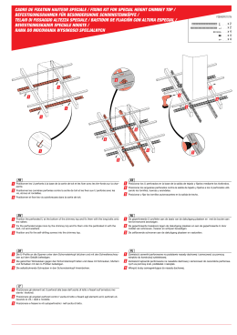
ISTRUZIONI DI MONTAGGIO PER SERRATURE CON AGGANCI A VITE
ASSEMBLING INSTRUCTIONS FOR LOCKS WITH SCREW HOOKINGS
INSTRUCTIONS DE MONTAGE POUR SERRURES A FIXATION PAR VIS
INSTRUCCIONES PARA EL MONTAJE DE CERRADURAS MEDIANTE ENGANCHE CON TORNILLO
Art. 9811 - 9831
Art. 7811 - 7831
Per rendere la serratura sinistra, svitare la vite solo il necessario
per fare fuoriuscire lo scrocco dal frontale, ruotarlo, riavvitare
serrando con forza.
To make the lock left-hand, unscrew the screw the necessary
lenght to make the latch come out of the face plate, turn it,
and screw down completely.
Pour la réversibilité du pêne dormant: dévisser la vis le
nécessaire pour faire sortir le pêne demi-tour de la têtière, le
faire tourner et revisser la vis à fond.
Para la utilización izquierda de la cerradura: aflojar el
tornillo solamente lo necessario para que el picaporte
salga de la parte frontal. Girarlo y reenroscar apretando
con fuerza.
N.B.
Art. 9611 - 9631
Con catenaccio fuori.
Bolt out.
Pêne dormant sorti.
Cerrojo hacia fuera.
Per rendere la serratura sinistra inserire un cacciavite nell'apposito foro e, utilizzandolo come leva, spingere lo scrocco fuori dal frontale,
ruotarlo e reinserirlo nella apposita sede.
To make the lock left-hand, insert a screwdriver into the special hole and use it as a lever. Push the latch out of the face plate, turn it, and
insert it again in its seat.
Pour la réversibilité du pêne dormant: introduire dans le trou correspondant un tournevis. En utilisant le tournevis comme un levier, pousser
le pêne demi-tour hors de la têtière, le faire tourner et le reintroduire dans son logement.
Para la utilización izquierda de la cerradura utilizar un destornillador introduciéndolo en el agujero señalado presionando el resbalon
hacia el exterior y fijarlo en la posición vertical.
Art. 9812 - 9832
Art. 7812 - 7832
Art. 9612 - 9632
x
20
15
Ma
ma
x
Regolazione della sporgenza del rullo.
Adjustment of the roller projection.
Réglage de la saillie du pêne rouleau.
Regolazione della sporgenza del rullo.
Réglage de la saillie du pêne rouleau.
Regulación resalto rodillo.
Adjustment of the roller projection.
Regulación resalto rodillo.
Art. 7817 - 7818 - 7838
Art. 9819 - 9839
Art. 9619 - 9639
B
B
A
B
A
A
A
A
B
B
Per rendere la serratura sinistra, svitare la vite dello scrocco "A" solo
il necessario per farlo fuoriuscire dal frontale, ruotarlo, riavvitare la
vite e serrarla con forza.
Ripetere la stessa operazione per il pistone "B".
To make the lock left-hand, unscrew the screw of the latch "A" the
necessary lenght to make it come out of the face plate, turn it,
and screw down completely.
Repeat the same with pin "B".
Pour la réversibilité du pêne dormant: dévisser la vis le nécessaire
pour faire sortir le pêne demi-tour "A" de la têtière, le faire tourner et
revisser la vis à fond.
Répéter la même operation avec le piston "B".
KW 11570
Para la utilización izquierda de la cerradura: aflojar el tornillo
solamente lo necessario para que el picaporte "A" salga de la
parte frontal. Girarlo y reenroscar apretando con fuerza.
Repetir la misma operación con el pistòn "B"
UTILIZZARE SOLAMENTE TRASFORMATORI
USE TRANSFORMERS ONLY
UTILISER SEULEMENT DES TRANSFORMATEURS
UTILIZAR SOLAMENTE TRANSFORMADORES
Per rendere la serratura sinistra inserire un cacciavite nell'apposito foro per lo scrocco "A" e, utilizzandolo come leva, spingere lo scrocco fuori dal
frontale, ruotarlo e reinserirlo nella propria sede. Ripetere la stessa operazione con il pistone "B".
To make the lock left-hand, insert a screwdriver into the special hole for the latch "A"and use it as a lever. Push the latch out of the face plate, turn it,
and insert it again in its seat Repeat the same with pin "B".
Pour la réversibilité du pêne dormant: introduire dans le trou correspondant pour le pêne demi-tour "A" un tournevis. En utilisant le tournevis comme un
levier, pousser le pêne demi-tour hors de la têtière, le faire tourner et le reintroduire dans son logement.Répéter la même operation avec le piston "B".
Para la utilización izquierda de la cerradura utilizar un destornillador introduciéndolo en el agujero señalado "A" presionando el
resbalon hacia el exterior y fisarlo en la posiciòn vertical. Repetir la misma operaciòn con el pistòn "B".
Art. 7817 - 7818 - 7838
Art. 9819 - 9839 - 9619 - 9639
Utilizzare cavi di sezione proporzionale alla lunghezza del circuito.
Sezione Cavo
Lungh. Circuito
Wire size
Circuit Lenght
Section Câble Longueur Circuit
Secciòn Cable Longitud Circuito
mm²
mm²
UTILIZZARE SOLAMENTE TRASFORMATORI
USE TRANSFORMERS ONLY
UTILISER SEULEMENT DES TRANSFORMATEURS
UTILIZAR SOLAMENTE TRANSFORMADORES
Use wires with a size proportional to the circuit lenght.
12 V ~ 15 W
Utiliser des câbles avec une section proportionelle à la longueur du circuit.
Utilizar cables de sección proporcionales a la longitud del circuito.
0,75
1,5
2,5
4
0 ÷ 50
50 ÷ 100
100 ÷ 150
> 150
12 V ~ 15 W
Art. 7820 - 78*1 - 78*2 - 78*3 - 78*4 - 7817 - 78*8
Istruzioni di montaggio del cilindro con chiave a spillo art. 8908** su serrature da montante.
Assembling instructions for the cylinder with cross key art. 8908** for locks to leading stile.
Instructions de montage pour cylindre avec clé à croix art. 8908** sur des serrures à larder.
instrucciones para el montaje con llave en cruz art. 8908** para cerraduras de enbutir.
3
2
1
4
Figure relative alle istruzioni di montaggio delle serrature triplici A-B-C-D-E-F.
Figures concerning the assembling instructions for the three way locking systems A-B-C-D-E-F.
Figures des instructions de montage des serrures triples A-B-C-D-E-F.
Figuras correspondientes a las instrucciones par el montaje de cerraduras triplìces A-B-C-D-E-F.
Inserimento puntale
Insert the tip
Introdution de l'embout
Insertar el puntal
Aggancio dell'asta interna
Internal rod hooking
Fixation de la tringle interne
Enganche varilla interna
Bloccaggio dell'asta interna
Internal rod blocking
Blocage de la tringle interne
Fijaciòn varilla interna
Boccola guida asta
Rod guide bush
Anneau guide de tringle
Buje guía varilla
10
58
Vite aggancio asta
Rod hooking screw
Vis de fixation de la tringle
Tornillo para fijación de varillas
Fig. 1
Fig. 2
Aggancio dell'asta esterna tramite piastrina
External rod hooking by coupling plate
Fixation de la tringle externe par la platine
Enganche varilla externa mediante placas de unión
Fig. 3
Ø8
Aggancio dell'asta esterna direttamente al rinvio
External rod hooking directly to the through and return mechanisms
Fixation de la tringle externe directement sur les mécanismes de renvoi
Enganche varilla externa directamente a la transmisión
Vite aggancio asta
Rod hooking screw
Vis de fixation de la tringle
Tornillo para fijación de varillas
Vite aggancio asta
Rod hooking screw
Vis de fixation de la tringle
Tornillo para fijación de varillas
Fig. 4
Ø6.5
6.5
Fig. 5
Art. 9831- 9832-9833-9839
Ø1
Art. 9631-9632-9633-9639
Ø1
4
Ø1
4
50
34
4
Ø3
0
Ø2
84
22
72
20
22
.5
.5
50
67
50
67
50
0
Ø2
185
185
85
250 *(305)
10
Ø
8.5
50
50
4
15
Art. 7820-7831-7832-7833-7834-7838
66
A
Chiusura triplice con aste interne art. 990850-990851
Three way locking system with internal rods art. 990850 - 990851
Fermeture triple par tringles internes art. 990850-990851
Cierre triplíce mediante varillas internas art. 990850 - 990851
Ø1
Ø1
4
4
Ø1
*(305) = quota per elettroserratura
unit for electric lock
cote pour serrures electriques
cota para cerraduras electricas
Fig. A1
957
957
893
1050
1050
965
4
Fig. A2
Fig. A3
1) Eseguire le lavorazioni per la serratura e i 2 fori Ø 14 per le boccole guida aste.
Fig. A1/A2/A3
2) Stabilire la lunghezza delle aste in posizione di porta aperta sottraendo la misura
del corpo Ø 8 del puntale (58 mm).
3) Inserire i puntali nelle aste mandando in appoggio il corpo Ø 8 sull'asta.
Stringere l'asta con una pinza in corrispondenza della gola sul puntale a circa
10 mm. Fig. 1
4) Inserire le boccole guida aste nel profilo. Introdurre le aste attraverso la cava
della serratura e inserirle nelle boccole di guida.
5) Posizionare la serratura nel profilo con il catenaccio rientrato.
6) Con la chiave far fuoriuscire il catenaccio.
7) Allineare i fori delle aste ai fori sul frontale della serratura.
8) Agganciare le aste ai rinvii tramite le apposite viti inserite attraverso i fori sul
frontale utilizzando una chiave esagonale da 2,5 mm.
N.B. avvitare le viti completamente in battuta sui rinvii. Fig. 2
9) Fissare la serratura.
10) Per facilitare eventuali operazioni di smontaggio della serratura è possibile
bloccare le aste avvitando le viti delle boccole guida. Fig. 3
1) Perform the work for the lock and the 2 Ø 14 holes for the rod guide bushes,
Fig. A1/A2/A3
2) Establish the length of the rods in the door open position, by subtracting the size
of the Ø 8 body from the tip (58 mm.).
3) Insert the tips into the rods pushing the Ø 8 body against the rod.
Tighten the rod with pliers in correspondence with the groove on the tip at
around 10 mm. Fig. 1
4) Insert the rod guide bushes into the profile. Introduce the rods through the recess
of the lock and insert them into the guide bushes.
5) Position the lock in the profile with the bolt drawn back.
6) Make the bolt come out using the key.
7) Line up the holes of the rods with the holes on the face plate of the lock.
8) Hook the rods to the through and return mechanisms using the special screws
inserted through the holes on the face plate with a 2.5 mm. Allen wrench.
N.B.: Screw down the screws completely against the through and return
mechanisms Fig. 2
9) Fix the lock.
10) In order to facilitate any dismounting operations of the lock it is possible to block
the rods by screwing the guide bushes Fig. 3
1) Exécuter les traveaux de préparation de la serrure ainsi que les 2 trous Ø 14
pour les anneaux guide de tringle Fig. A1/A2/A3
2) Etablir la longueur des tringles, à porte ouverte, en soustrayant la mesure du
corps Ø 8 de l'embout (58 mm).
3) Introduire les embouts dans les tringles en pressant le corps Ø 8 sur la tringle.
Serrer la tringle, à l'aide d'une pince, en correspondance de la gorge sur
l'embout à environ 10 mm Fig. 1
4) Introduire les anneaux guide de tringle dans le profilé. Introduire les tringles à
travers la rainure de la serrure et les introduire dans les anneaux guide de tringle.
5) Positionner la serrure dans le profilé avec le pêne dormant rentré.
6) Faire sortir le pêne dormant à l'aide de la clé.
7) Aligner les trous des tringles aux trous sur la têtière de la serrure.
8) Fixer les tringles aux mécanismes de renvoi au moyen des vis correspondantes
qui sont déjà introduites dans les trous sur la têtière, en utilisant une clé à six pans
de 2,5 mm. N.B. serrer les vis en butée sur les mécanismes de renvoi Fig. 2
9) Fixer la serrure.
10) Pour éventuellement faciliter le démontage de la serrure, on peut bloquer les
tringles en vissant les vis des anneaux guide de tringle Fig. 3
1) Efectuar las operaciones necesarias para preparar la cerradura y los 2 agujeros
Ø 14 para los bujes guía varillas Fig. A1/A2/A3
2) Determinar la longitud de las varillas con la puerta en posición abierta
sustrayendo la medida del cuerpo Ø 8 del puntal (58 mm).
3) Introducir los puntales en las varillas hasta que el cuerpo Ø 8 se encuentre
apoyado contra la varilla. Apretar la varilla con una pinza al nivel de la ranura
del puntal, a unos 10 mm. Fig. 1
4) Introducir los bujes guía varillas en el perfil. Introducir las varillas a través de la
cavidad de la cerradura y introducirlas en los bujes guía.
5) Colocar la cerradura dentro del perfil con el cerrojo hacia dentro.
6) Hacer salir el cerrojo utilizando la llave.
7) Alinear los agujeros de las varillas con los que se encuentran en la parte frontal
de la cerradura.
8) Enganchar las varillas a las contromarchas; para ello, introducir los tornillos
correspondientes dentro de los agujeros que se encuentran en la parte frontal,
utilizando una llave hexagonal de 2,5 mm. Fig. 2
9) Fijar la cerradura.
10) Para facilitar eventuales operaciones de desmontaje de la cerradura, se
pueden bloquear las varillas enroscando los tornillos de los bujes guía Fig. 3
Art. 9831- 9832-9833-9839
20
625
20
625
625
20
Art. 9631-9632-9633-9639
140
140
Ø1
Ø1
Ø1
50
4
Ø3
0
Ø2
20
.5
22
.5
50
67
50
67
50
0
Ø2
66
185
84
185
22
72
85
250 *(305)
10
50
4
4
Ø3
50
4
4
8.5
15
140
Art. 7820-7831-7832-7833-7834-7838
85
B
Chiusura triplice con deviatori ad aste interne art. 7803 02
Three way locking system with internal rod swing bolts art. 7803 02
Fermeture triple par tringles internes avec pênes basculants supplémentaires art. 7803 02
Cierre tríplice mediante varillas internas con desviadores art. 7803 02
Ø1
Ø1
4
4
Ø1
1050
625
140
1050
140
20
20
20
*(305) = quota per elettroserratura
unit for electric lock
cote pour serrures electriques
cota para cerraduras electricas
Fig. B1
202
202
138
140
965
625
625
4
Fig. B2
Fig. B3
1) Eseguire le lavorazioni per la serratura, per i deviatori e i 2 fori Ø 14 per le boccole guida aste.
Fig. B1/B2/B3
2) Inserire le boccole guida aste nel profilo.
3) Introdurre i deviatori con il catenaccio rientrato e inserire le aste nelle boccole di guida.
4) Spingendo le aste far fuoriuscire il catenaccio dei deviatori.
5) Posizionare la serratura nel profilo con il catenaccio rientrato.
6) Con la chiave far fuoriuscire il catenaccio.
7) Muovendo i deviatori allineare i fori delle aste ai fori del frontale.
8) Agganciare le aste ai rinvii tramite le apposite viti inserite attraverso i fori sul frontale utilizzando
una chiave esagonale da 2,5 mm.
N.B. avvitare le viti completamente in battuta sui rinvii. Fig. 2
9) Fissare la serratura.
10) Fissare i deviatori dal foro asolato con la vite a testa cilindrica.
11) Prima del definitivo fissaggio verificare le seguenti condizioni:
a) con il catenaccio della serratura rientrato i catenacci dei deviatori non devono sporgere dal
frontale;
b) con il catenaccio della serratura fuoriuscito i catenacci dei deviatori devono essere
completamente fuoriusciti e spingendo in senso contrario non devono rientrare ma rimanere
bloccati.
12) Se non è rispettata la condizione "a" bisogna allontanare il deviatore;
Se non è rispettata la condizione "b" bisogna avvicinare il deviatore.
1) Perform the work for the lock, the swing bolts and the 2 Ø 14 holes for the rod guide bushes
Fig. B1/B2/B3.
2) Insert the rod guide bushes into the profile.
3) Introduce the swing bolts with the bolt drawn back and insert the rods into the guide bushes.
4) By pushing the rods, make the bolt of the swing bolts come out.
5) Position the lock in the profile with the bolt drawn back.
6) Make the bolt come out using the key.
7) By moving the swing bolts line up the holes of the rods with the holes of the face plate.
8) Hook the rods to the through and return mechanisms using the special screws inserted through
the holes on the face plate with a 2.5 mm. Allen wrench.
N.B.: Screw down the screws completely against the through and return mechanisms Fig. 2
9) Fix the lock.
10) Fix the swing bolts from the slot with the cheese-headed screw.
11) Before definitive fixing, check the following conditions:
a) with the lock bolt drawn back, the bolts of the swing bolts must not protrude from the face
plate.
b) with the lock bolt out, the bolts of the swing bolts must be completely out and when pushed
in the opposite direction they must not draw back, but remain blocked.
12) If condition "a" is not respected, it is necessary to take the swing bolts back;
If condition "b" is not respected, it is necessary to move the swing bolts closer.
1) Exécuter les travaux de préparation de la serrure, les pênes basculants supplémentaires ainsi
que les 2 trous Ø 14 pour les anneaux guide de tringle Fig. B1/B2/B3
2) Introduire les anneaux guide de tringle dans le profilé.
3) Introduire les pênes basculants supplémentaires avec le pêne dormant rentré et introduire les
tringles dans les anneaux guide de tringle.
4) En poussant les tringles faire sortir le pêne dormant des pênes basculants supplémentaires.
5) Positionner la serrure dans le profilé avec le pêne dormant rentré.
6) Faire sortir le pêne dormant à l'aide de la clé.
7) En déplaçant les pênes basculants supplémentaires, aligner les trous des tringles aux trous de
la
têtière.
8) Fixer les tringles aux mécanismes de renvoi au moyen des vis correspondantes qui sont déjà
introduites dans les trous sur la têtière, en utilisant une clé à six pans de 2,5 mm.
N.B. Serrer les vis en butée sur les mécanismes de renvoi Fig. 2
9) Fixer la serrure.
10) Fixer les pênes basculants supplémentaires de la fente au moyen de la vis à tête cylindrique.
11) Avant le fixage définitif, vérifier les conditions suivantes:
a) lorsque le pêne dormant de la serrure est rentré, les pênes dormants des pênes basculants
supplémentaires ne doivent pas dépasser de la têtière.
b) lorsque le pêne dormant de la serrure est sorti, les pênes dormants des pênes basculants
supplémentaires doivent être complètement sortis et lorsqu'on pousse dans le sens contraire, ils
ne doivent pas rentrer, mais rester bloqués.
12) Si la condition "a" n'est pas respectée, il faut éloigner le pêne basculant supplémentaire.
1) Efectuar las operaciones necesarias para preparar la cerradura, los desviadores y los 2
agujeros
Ø 14 para los bujes guía varillas. Fig. B1/B2/B3
2) Introducir los bujes guía varillas en el perfil.
3) IIntroducir los desviadores con el cerrojo hacia dentro y introducir las varillas en los bujes guía.
4) Empujar las varillas para que el cerrojo salga de los desviadores.
5) Colocar la cerradura dentro del perfil con el cerrojo hacia dentro.
6) Hacer salir el cerrojo utilizando la llave.
7) Alinear los agujeros de las varillas con los que se encuentran en la parte frontal de la
cerradura;
para ello, mover los desviadores.
8) Enganchar las varillas a las contromarchas; para ello, introducir los tornillos correspondientes
dentro de los agujeros que se encuentran en la parte frontal utilizando una llave hexagonal de
2,5 mm. N.B. Enroscar los tornillos a fondo hasta que estén en contacto con las
contromarchas,
Fig. 2.
9) Fijar la cerradura
10) Fijar los desviadores a través del agujero-ojal con el tornillo de cabeza cilíndrica.
11) Antes de realizar la fijación definitiva, asegurarse de que se cumplen las siguientes
condiciones:
a) cuando el cerrojo de la cerradura está metido hacia dentro, los cerrojos de los desviadores
no deben asomar fuera de la parte frontal.
b) cuando el cerrojo de la cerradura está salido hacia fuera, los cerrojos de los desviadores
Chiusura triplice con aste esterne agganciate tramite piastrina di collegamento art. 990853
Three way locking system with external rods hooked with a coupling plate art. 990853
Fermeture triple par tringles externes fixées au moyen de la platine de jonction art. 990853
Cierre triplíce mediante varillas externas enganchadas por medio de una placa de unión art. 990853.
Art. 9831- 9832-9833-9839
Art. 9631-9632-9633-9639
22
.5
957
1050
1050
67
893
957
15
22
.5
67
965
0
Ø2
8.5
Ø8
10
185
4
Ø3
185
0
Ø2
84
Ø8
20
72
85
250 *(305)
Ø8
Ø3
66
4
12.5
25
Art. 7820-7831-7832-7833-7834-7838
12.5
C
*(305) = quota per elettroserratura
unit for electric lock
cote pour serrures electriques
cota para cerraduras electricas
Fig. C1
Fig. C2
Fig. C3
1) Eseguire le lavorazioni per la serratura. Fig. C1/C2/C3
2) Stabilire la lunghezza delle aste in posizione di porta aperta considerando
eventuali puntali normalmente reperibili in commercio.
3) Eseguire sulle aste i fori Ø 8 di aggancio ai rinvii.
4) Infilare le aste nel profilo e inserire le piastrine nei fori Ø 8.
5) Posizionare la serratura nel profilo con il catenaccio rientrato.
6) Con la chiave far fuoriuscire il catenaccio.
7) Inserire gli spessori sottofrontale che tengono in guida le piastrine.
8) Agendo sulle aste allineare i fori delle piastrine ai fori sul frontale.
9) Agganciare le piastrine ai rinvii tramite le apposite viti inserite attraverso i fori sul
frontale utilizzando una chiave esagonale da 2,5 mm.
N.B. avvitare le viti completamente in battuta sui rinvii. Fig. 4
10) Fissare la serratura.
1) Perform the work for the lock, Fig. C1/C2/C3
2) Establish the length of the rods in the door open position, considering any tips
normally available on the market.
3) Perform the Ø 8 holes in the rods for hooking the through and return
mechanisms
4) Slide the rods into the profile and insert the plates into the Ø 8 holes.
5) Position the lock in the profile with the bolt drawn back.
6) Make the bolt come out using the key.
7) Insert the under face plate spacers which guide the plates.
8) By acting on the rods, line up the holes of the plates with the holes on the face
plate.
9) Hook the plates to the through and return mechanisms with the special screws
inserted through the holes on the face plate by using a 2.5 mm. Allen wrench.
N.B.: Screw down the screws completely against the through and return
mechanisms, Fig. 4
10) Fix the lock.
1) Exécuter les travaux de préparation de la serrure Fig. C1/C2/C3
2) Etablir la longueur des tringles, à porte ouverte, en tenant compte des embouts
que l'on peut trouver dans le commerce
3) Faire des trous de Ø 8 de fixation aux mécanismes de renvoi sur les tringles.
4) Introduire les tringles dans le profilé et introduire les platines dans les trous Ø 8.
5) Positionner la serrure dans le profilé avec le pêne dormant rentré.
6) Faire sortir le pêne dormant à l'aide de la clé.
7) Introduire les cales sous-têtière qui tiennent les platines en place.
8) En agissant sur les tringles, aligner les trous des platines aux trous de la têtière.
9) Fixer les platines aux mécanismes de renvoi au moyen des vis correspondantes
qui sont déjà introduites dans les trous sur la têtière, en utilisant une clé à six pans
de 2,5 mm.
N.B. Serrer les vis en butée sur les mécanismes de renvoi Fig. 4
10) Fixer la serrure.
1) Efectuar las operaciones necesarias para preparar la cerradura. Fig. C1/C2/C3
2) Determinar la longitud de las varillas con la puerta en posición abierta tomando
como referencia unos puntales que se encuentren normalmente en el comercio
3) Realizar en las varillas los agujeros de Ø 8 que servirán a engancharlas a las
contromarchas.
4) Introducir las varillas en el perfil. Introducir las placas en los agujeros de Ø 8.
5) Colocar la cerradura dentro del perfil con el cerrojo hacia dentro.
6) Hacer salir el cerrojo de la cerradura utilizando la llave.
7) Introducir debajo de la parte frontal las plaquitas que sirven de guía a las placas
de unión.
8) Moviendo las verillas, alinear los agujeros de las placas con los que se
encuentran en la parte frontal de la cerradura.
9) Enganchar las placas sobre las contromarchas; para ello, introducir los tornillos
correspondientes dentro de los agujeros que se encuentran en la parte frontal
utilizando una llave hexagonal de 2,5 mm.
N.B.: Enroscar los tornillos a fondo hasta que estén en contacto con las
contromarchas, Fig. 4
10) Fijar la cerradura.
Art. 9631-9632-9633-9639
20
140
140
Art. 9831- 9832-9833-9839
20
X
X
X-77
X
X-65
X-77
Ø8
20
Ø8
20
Ø8
20
140
Art. 7820-7831-7832-7833-7834-7838
20
D
Chiusura triplice con deviatori ad aste esterne art. 7803 22 e piastrine art. 990853
Three way locking system with external rod swing bolts art. 7803 22 and coupling plates art. 990853
Fermeture triple par tringles externes avec pênes basculants supplémentaires art. 7803 22 et platines art. 990853.
Cierre triplíce mediante varillas externas con desviadores art. 7803 22 y placas de unión art. 990853.
4
8.5
185
12.5
185
84
22
.5
22
67
Ø8
.5
12.5
0
Ø2
66
10
85
72
250 *(305)
25
Ø8
20
0
Ø2
15
Ø3
4
Ø3
1050
1050
X
20
*(305) = quota per elettroserratura
unit for electric lock
cote pour serrures electriques
cota para cerraduras electricas
Fig. D1
20
202
202
140
140
20
138
140
965
X
X
Ø8
67
Fig. D2
Fig. D3
1) Eseguire le lavorazioni per la serratura e i deviatori. Fig. D1/D2/D3
2) Tagliare le aste alla misura X-65 per serrature da montante Fig. D1; X-77 per serrature da fascia
Fig. D2 e Fig. D3
3) Eseguire sulle aste i 4 fori di aggancio Ø 8.
4) Inserire le aste nel profilo con le 4 piastrine di collegamento.
5) Posizionare la serratura nel profilo con il catenaccio rientrato.
6) Inserire il cilindro e far fuoriuscire il catenaccio. Inserire gli spessori sottofrontale.
7) Allineare i fori delle piastrine ai fori sul frontale della serratura.
8) Agganciare le piastrine ai rinvii tramite le apposite viti inserite attraverso i fori sul frontale utilizzando una
chiave esagonale da 2,5 mm. Fig. 4
N.B. avvitare le viti completamente in battuta sui rinvii.
9) Fissare la serratura e far rientrare il catenaccio.
10) Posizionare i deviatori nel profilo con il catenaccio fuoriuscito.
11) Con la chiave far fuoriuscire il catenaccio della serratura.
12) Allineare i fori sul frontale dei deviatori ai fori delle piastrine.
13) Agganciare le piastrine ai rinvii tramite le viti come per la serratura.
14) Fissare i deviatori dal foro asolato con la vite a testa cilindrica
15) Prima del definitivo fissaggio verificare le seguenti condizioni:
a) con il catenaccio della serratura rientrato i catenacci dei deviatori non devono sporgere dal frontale;
b) con il catenaccio della serratura fuoriuscito i catenacci dei deviatori devono essere completamente
fuoriusciti e spingendo in senso contrario non devono rientrare ma
rimanere bloccati.
16) Se non è rispettata la condizione "a" bisogna allontanare il deviatore;
se non è rispettata la condizione "b" bisogna avvicinare il deviatore.
1) Perform the work for the lock and the swing bolts, Fig. D1/D2/D3
2) Cut the rods to the size: X - 65 for locks to leading stile Fig. D1; X-77 for the locks to mid rail
Fig. D2 and Fig. D3
3) Make the 4 Ø 8 hooking holes in the rods.
4) Insert the rods into the profile with the 4 coupling plates.
5) Position the lock in the profile with the bolt drawn back.
6) Insert the cylinder and make the bolt come out. Insert the under face plate spacers.
7) Line up the holes of the plates with the holes on the face plate of the lock.
8) Hook the plates to the through and return mechanisms with the special screws inserted through the
holes
on the face plate using a 2.5 mm. Allen wrench, Fig. 4
N.B.: Screw down the screws completely against the through and return mechanisms.
9) Fix the lock and make the bolt draw back.
10) Position the swing bolts in the profile with the bolt out.
11) Make the bolt come out using the key.
12) Line up the holes on the face plate of the swing bolts with the holes of the plates.
13) Hook the plates to the through and return mechanisms with the screws as for the lock.
14) Fix the swing bolts from the slot with the cheese-headed screw.
15) Before definitive fixing, check the following conditions:
a) with the lock bolt drawn back the bolts of the swing bolts must not protrude from the face plate.
b) with the lock bolt out the bolts of the swing bolts must be completely out and when pushed in the
opposite direction they must not draw back, but remain blocked.
16) If condition "a" is not respected, it is necessary to take the swing bolts back;
If condition "b" is not respected, it is necessary to move the swing bolts closer.
1) Exécuter les travaux de préparation de la serrure et les pênes basculants supplémentaires Fig. D1/D2/D3
2) Couper les tringles de la mesure de: X-65 pour serrures à larder Fig. D1; X-77 pour serrures en aluminium
Fig. D2 et Fig. D3
3) Faire 4 trous de fixation de Ø 8 sur les tringles.
4) Introduire les tringles dans le profilé avec les 4 platines de jonction.
5) Positionner la serrure dans le profilé avec le pêne dormant rentré.
6) Introduire le cylindre et faire sortir le pêne dormant. Introduire les cales sous-têtière.
7) Aligner les trous des platines aux trous sur la têtière de la serrure.
8) Fixer les platines aux mécanismes de renvoi au moyen des vis correspondantes qui sont déjà introduites
sur la têtière, en utilisant une clé à six pans de 2,5 mm Fig. 4
N.B. Serrer les vis en butée sur les mécanismes de renvoi.
9) Fixer la serrure et faire rentrer le pêne dormant.
10) Mettre les pênes basculants supplémentaires en place dans le profilé, pêne dormant sorti.
11) Faire sortir le pêne dormant de la serrure à l'aide de la clé.
12) Aligner les trous sur la têtière des pênes basculants supplémentaires aux trous des platines.
13) Fixer les platines sur les mécanismes de renvoi au moyen de vis, comme pour la serrure.
14) Fixer les pênes basculants supplémentaires de la fente au moyen de la vis à tête cylindrique.
15) Avant le fixage définif, vérifier les conditions suivantes:
a) lorsque le pêne dormant de la serrure est rentré, les pênes dormants des pênes basculants
supplémentaires ne doivent pas dépasser de la têtière.
b) lorsque le pêne de la serrure est sorti, les pênes dormants des pênes basculants supplémentaires
doivent être complè tement sortis et lorsqu'on pousse dans le sens contraire ils ne doivent pas rentrer
mais rester bloqués.
16) Si la condition "a" n'est pas respectée, il faut éloigner le pêne basculant supplémentaire;
Si la condition "b" n'est pas respectée, il faut approcher le pêne basculant supplémentaire.
1) Efectuar las operaciones necesarias para preparar la cerradura y los desviadores Fig. D1/D2/D3
2) Cortar las varillas dándoles las medidas siguientes: X-65 para cerraduras de embutir Fig. D1; X-77 para
cerraduras para perfil de aluminiom Fig. D2 y Fig. D3
3) Realizar en las varillas los 4 agujeros de Ø 8 que servirán a engancharlas.
4) Introducir las varillas en el perfil con las 4 placas de unión.
5) Colocar la cerradura dentro del perfil con el cerrojo hacia dentro.
6) Introducir el cilindro y hacer salir el cerrojo. Introducir las plaquitas de cerrojo debajo de la parte frontal.
7) Alinear los agujeros de las varillas con los que se encuentran en la parte frontal de la cerradura.
8) Enganchar las placas sobre las contromarchas; para ello, introducir los tornillos correspondientes dentro
de los agujeros que se encuentran en la parte frontal utilizando una llave hexagonal de 2,5 mm. Fig. 4
N.B. Enroscar los tornillos a fondo hasta que estén en contacto con las contromarchas.
9) Fijar la cerradura y meter el cerrojo hacia dentro.
10) Colocar los desviadores dentro del perfil con el cerrojo hacia fuera.
11) Hacer salir el cerrojo de la cerradura utilizando la llave.
12) Alinear los agujeros que se encuentran en la parte frontal de los desviadores con los de las placas.
13) Enganchar las placas a las contromarchas utilizando los tornillos, de la misma manera que para la
cerradura
14) Fijar los desviadores a través del agujero-ojal con el tornillo de cabeza cilíndrica.
15) Antes de realizar la fijación definitiva, asegurarse de que se cumplen las siguientes condiciones:
a) cuando el cerrojo de la cerradura está metido hacia dentro, los cerrojos de los desviadores no deben
asomar fuera de la parte frontal.
b) cuando el cerrojo de la cerradura está salido hacia fuera, los cerrojos de los desviadores deben
asomar completamente hacia fuera, y si se ejerce una presión en sentido contrario, no deben meterse
hacia dentro sino permanecer bloqueados.
16) Si no se cumple la condición "a", es preciso alejar el desviador;
Chiusura triplice con aste esterne agganciate direttamente
Three way locking system with directly hooked external rods.
Fermeture triple par tringles externes à fixation directe
Cierre triplíce mediante varillas externas enganchadas directamente.
Art. 9831- 9832-9833-9839
Art. 9631-9632-9633-9639
Ø6
.5
Ø6
29
10
10
20
4
Ø3
.5
0
Ø2
185
66
10
185
0
Ø2
22
.5
.5
67
957
67
1050
.5
22
957
Ø6
84
85
20
72
.5
965
Ø6
893
7
20
20
7
.5
250 *(305)
24
Ø6
24
Ø6
4
Ø3
.5
.5
8.5
15
7
Ø6
Ø6
Ø6
.5
29
.5
1050
28
25
Art. 7820-7831-7832-7833-7834-7838
28
E
Ø6
.5
*(305) = quota per elettroserratura
unit for electric lock
cote pour serrures electriques
cota para cerraduras electricas
Fig. E1
Fig. E2
Fig. E3
1) Eseguire le lavorazioni per la serratura. Fig. E1/E2/E3
2) Stabilire la lunghezza delle aste in posizione di porta aperta considerando
eventuali puntali normalmente reperibili in commercio.
3) Eseguire sulle aste i fori Ø 6.5 di aggancio e le 2 asole di scarico.
4) Infilare le aste nel profilo.
5) Posizionare la serratura nel profilo con il catenaccio rientrato.
6) Con la chiave far fuoriuscire il catenaccio.
7) Allineare i fori Ø 6.5 delle aste ai fori sul frontale della serratura.
8) Agganciare le aste ai rinvii tramite le apposite viti inserite attraverso i fori sul
frontale utilizzando una chiave esagonale da 2,5 mm.
N.B. avvitare le viti completamente in battuta sui rinvii. Fig. 5
9) Fissare la serratura.
1) Perform the work for the lock, Fig. E1/E2/E3
2) Establish the length of the rods in the door open position by considering tips
normally available on the market.
3) Perform the Ø 6.5 hooking holes and the two slots in the rods.
4) Slide the rods into the profile.
5) Position the lock in the profile with the bolt drawn back.
6) Make the bolt come out using the key.
7) Line up the Ø 6.5 holes of the rods with the holes on the lock face plate.
8) Hook the rods to the through and return mechanisms with the special screws
inserted through the holes in the face plate using a 2.5 mm. Allen wrench.
N.B.: Screw down the screws completely against the through and return
mechanisms. Fig. 5
9) Fix the lock.
1) Exécuter les travaux de préparation de la serrure Fig. E1/E2/E3
2) Etablir la longueur des tringles à porte ouverte, en tenant compte des embouts
que l'on peut trouver dans le commerce.
3) Faire des trous de fixation de Ø 6,5 et les deux fentes sur les tringles.
4) Introduire les tringles dans le profilé.
5) Positionner la serrure dans le profilé avec le pêne rentré.
6) Faire sortir le pêne dormant à l'aide de la clé.
7) Aligner les trous Ø 6,5 des tringles aux trous sur la têtière de la serrure.
8) Fixer les tringles aux mécanismes de renvoi au moyen des vis correspondantes qui
sont déjà introduites dans les trous sur la têtière, en utilisant une clé à six pans de
2,5 mm. N.B. Serrer les vis en butée sur les mécanismes de renvoi Fig. 5
9) Fixer la serrure.
1) Efectuar las operaciones necesarias para preparar la cerradura Fig. E1/E2/E3
2) Determinar la longitud de las varillas con la puerta en posición abierta tomando
como referencia unos puntales que se encuentren normalmente en el comercio.
3) Realizar en las varillas los agujeros de Ø 6,5 que servirán a engancharlas y los 2
agujeros-ojals.
4) Introducir las varillas en el perfil.
5) Colocar la cerradura dentro del perfil con el cerrojo hacia dentro.
6) Hacer salir el cerrojo utilizando la llave.
7) Alinear los agujeros de Ø 6,5 de las placas con los que se encuentran en la parte
frontal de la cerradura.
8) Enganchar las placas sobre las contromarchas; para ello, introducir los tornillos
correspondientes dentro de los agujeros que se encuentran en la parte frontal
utilizando una llave hexagonal de 2,5 mm.
N.B. Enroscar los tornillos a fondo hasta que estén en contacto con las
contromarchas, Fig. 5
9) Fijar la cerradura.
Chiusura triplice con deviatori ad aste esterne art. 7803 22 agganciate direttamente
Three way locking system with directly hooked external rod swing bolts art. 7803 22
Fermeture triple par tringles externes avec pênes basculants supplémentaires à fixation directe art. 7803 22
Cierre triplíce mediante varillas externas con desviadores art. 7803 22 enganchadas directamente
.5
Ø6
.5
20
Ø6
.5
X
X
4
8.5
185
.5
22
22
.5
7
.5
Ø6
67
.5
0
Ø2
66
28
Ø6
29
84
29
185
.5
Ø6
7
4
Ø3
0
Ø2
10
Ø6
7
20
72
.5
85
250 *(305)
Ø6
20
25
28
Ø3
15
X
7
Ø6
X+53
.5
20
29
29
20
.5
140
Ø6
20
20
Ø6
X+50
24
25
.5
Art. 9631-9632-9633-9639
X+53
Ø6
Art. 9831- 9832-9833-9839
7
7
140
Art. 7820-7831-7832-7833-7834-7838
140
F
67
.5
Ø6
*(305) = quota per elettroserratura
unit for electric lock
cote pour serrures electriques
cota para cerraduras electricas
20
1050
20
202
202
Fig. F1
X
140
1050
X
140
965
20
138
140
X
.5
Fig. F2
Fig. F3
1) Eseguire le lavorazioni per la serratura e i deviatori. Fig. F1/F2/F3
2) Tagliare le aste alla misura X+50 per le serrature da montante Fig. F1; X+53 per le serrature da fascia
Fig. F2 e Fig. F3
3) Eseguire sulle aste i 4 fori di aggancio Ø 6,5 e le 4 asole di scarico.
4) Posizionare la serratura nel profilo con il catenaccio rientrato.
5) Con la chiave far fuoriuscire il catenaccio.
6) Allineare i fori Ø 6,5 delle aste ai fori sul frontale della serratura.
7) Agganciare le aste ai rinvii tramite le apposite viti inserite attraverso i fori sul frontale utilizzando una chiave
esagonale da 2,5 mm.
N.B. avvitare le viti completamente in battuta sui rinvii. Fig. 5
8) Fissare la serratura e far rientrare il catenaccio.
9) Posizionare i deviatori nel profilo con il catenaccio rientrato.
10) Con la chiave far fuoriuscire il catenaccio della serratura.
11) Allineare i fori sul frontale dei deviatori ai fori Ø 6,5 delle aste.
12) Agganciare le aste ai rinvii tramite le viti come per la serratura.
13) Fissare i deviatori dal foro asolato con la vite a testa cilindrica
14) Prima del definitivo fissaggio verificare le seguenti condizioni:
a) con il catenaccio della serratura rientrato i catenacci dei deviatori non devono sporgere dal frontale;
b) con il catenaccio della serratura fuoriuscito i catenacci dei deviatori devono essere completamente
fuoriusciti e spingendo in senso contrario non devono rientrare ma
rimanere bloccati.
15) Se non è rispettata la condizione "a" bisogna allontanare il deviatore;
se non è rispettata la condizione "b" bisogna avvicinare il deviatore.
1) Perform the work for the lock and the swing bolts, Fig. F1/F2/F3
2) Cut the rods to the size: X + 50 for locks to leading stile Fig. F1; X + 53 for locks to mid rail
Fig. F2 and Fig. F3
3) Perform the 4 Ø 6.5 hooking holes and the 4 slots in the rods.
4) Position the lock in the profile with the bolt drawn back.
5) Make the bolt come out using the key.
6) Line up the Ø 6.5 holes of the rods with the holes on the face plate of the lock.
7) Hook the rods to the through and return mechanisms with the special screws inserted through the holes in
the face plate using a 2.5 mm. Allen wrench.
N.B.: Screw down the screws completely against the through and return mechanisms. Fig. 5
8) Fix the lock and make the bolt draw back.
9) Position the swing bolts in the profile with the bolt drawn back.
10) Make the look bolt come out using the key.
11) Line up the holes on the face plate of the swing bolts with the Ø 6.5 holes of the rods.
12) Hook the rods to the through and return mechanisms with the screws as for the lock.
13) Fix the swing bolts from the slot with the cheese-headed screw.
14) Before definitive fixing, check the following conditions:
a) with the lock bolt drawn back the bolts of the swing bolts must not protrude from the face plate.
b) with the lock bolt out the bolts of the swing bolts must be completely out and when pushed in the
opposite direction they must not draw back, but remain blocked.
15) If condition "a" is not respected, it is necessary to take the swing bolts back;
If condition "b" is not respected, it is necessary to move the swing bolts closer.
1) Exécuter les travaux de préparation de la serrure et des pênes basculants supplémentaires Fig. F1/F2/F3
2) Couper les tringles de la mesure de:X + 50 pour serrures a larder Fig. F1; X + 53 pour serrures en
aluminium Fig. F2 et Fig. F3
3) Faire les 4 trous de fixation de Ø 6,5 et les 4 fentes sur les tringles.
4) Positionner la serrure dans le profilé avec le pêne dormant rentré.
5) Faire sortir le pêne dormant à l'aide de la clé.
6) Aligner les trous de Ø 6,5 des tringles aux trous sur la têtière de la serrure.
7) Fixer les tringles aux mécanismes de renvoi au moyen des vis correspondantes qui sont déjà introduites
dans les trous sur la têtière, en utilisant une clé à six pans de 2,5 mm.
N.B. Serrer les vis en butée sur les mécanismes de renvoi Fig. 5
8) Fixer la serrure et faire rentrer le pêne dormant.
9) Positionner les pênes basculants supplémentaires dans le profilé avec le pêne dormant rentré.
10) Faire sortir le pêne dormant de la serrure à l'aide de la clé.
11) Aligner les trous sur la têtière des pênes basculants supplémentaires aux trous Ø 6,5 des tringles.
12) Fixer les tringles sur les mécanismes de renvoi au moyen des vis, comme pour la serrure.
13) Fixer les pênes basculants supplémentaires de la fente au moyen de la vis à tête cylindrique.
14) Avant le fixage définif, vérifier les conditions suivantes:
a) lorsque le pêne dormant de la serrure est rentré, les pênes dormants des pênes basculants
supplémentaires ne doivent pas dépasser de la têtière.
b) lorsque le pêne dormant de la serrure est sorti, les pênes dormants des pênes basculants
supplémentaires doivent être complè tement sortis et lorsqu'on pousse dans le sens contraire ils ne
doivent
pas rentrer mais rester bloqués.
15) Si la condition "a" n'est pas respectée, il faut éloigner le pêne basculant supplémentaire
1) Efectuar las operaciones necesarias para preparar la cerradura y los desviadores Fig. F1/F2/F3
2) Cortar las varillas dándoles las medidas siguientes: X+50 para cerraduras de embutir Fig. F1; X + 53 para
cerraduras para perfil de aluminiom Fig. F2 y Fig. F3
3) Realizar en las varillas los 4 agujeros de Ø 6,5 que servirán a engancharlas, así como los 4 agujeros-ojals.
4) Colocar la cerradura dentro del perfil con el cerrojo hacia dentro.
5) Hacer salir el cerrojo utilizando la llave.
6) Alinear los agujeros de Ø 6,5 de las varillas con los que se encuentran en la parte frontal de la cerradura.
7) Enganchar las varillas sobre las contromarchas; para ello, introducir los tornillos correspondientes dentro
de los agujeros que se encuentran en la parte frontal utilizando una llave hexagonal de 2,5 mm.
N.B. Enroscar los tornillos a fondo hasta que estén en contacto con las contromarchas, Fig. 5
8) Fijar la cerradura y meter el cerrojo hacia dentro.
9) Colocar los desviadores dentro del perfil con el cerrojo hacia dentro.
10) Hacer salir el cerrojo de la cerradura utilizando la llave.
11) Alinear los agujeros que se encuentran en la parte frontal de los desviadores con los de Ø 6.5 de las varillas
12) Enganchar las placas a las contromarchas utilizando los tornillos de la misma manera que para la
cerradura.
13) Fijar los desviadores a través del agujero-ojal con el tornillo de cabeza cilíndrica.
14) Antes de realizar la fijación definitiva, asegurarse de que se cumplen las siguientes condiciones:
a) cuando el cerrojo de la cerradura está metido hacia dentro, los cerrojos de los desviadores no deben
asomar fuera de la parte frontal.
b) cuando el cerrojo de la cerradura está salido hacia fuera, los cerrojos de los desviadores deben
asomar completamente hacia fuera, y si se ejerce una presión en sentido contrario, no deben meterse
hacia dentro sino permanecer bloqueados.
15) Si no se cumple la condición "a", es preciso alejar el desviador;
Scaricare