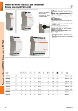
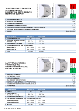
Con EURclass si gestiscono un ridotto numero di esecuzioni grazie a: 1 Secondario a tensione 12 e 24, 24 e 48, 55 e 110, 115 e 230V. 2 Primario per le più diffuse tensioni normalizzate che consentono di realizzare macchine utensili ed apparecchiature vendibili in ogni angolo della terra: - 110 (*), 230, 400V per le taglie ¿no a 160 VA; - 110 (*), 230, 400, 415 (*), 440 (*), 460 (*), 480V (*) per le taglie superiori. In ogni caso le prese + e - 15V possono fornire tensioni prossime a 240V o adattare primario e secondario a situazioni di linea con eccessive cadute o sovralimentate. Questa Àessibilità consente di coprire il 70 delle richieste di trasformatori in esecuzione speciale con 7 grandezze e 28 codici. A richiesta può essere fornito, nell’ambito delle esecuzioni di sicurezza, il secondario a 19 V per alimentare ponti ad onda intera a 24 Vcc. • Protezione contro contatti diretti e indiretti: classe II. • Grado di protezione: IP20. • Fissaggio su pro¿lato omega EN50022, CEI 96-7, EN 61558-2-6, EN 61558-2-4, CEI 96-9, EN 61558-2-2. • Frequenza nominale: 50÷60 Hz. • Classe termica: F. • Temperatura ambiente: 40°C. • Tensione di isolamento tra gli avvolgimenti: 5KVx1’. • Collegamento esterno: tipo X. Esecuzioni speciali • Massimo 10 terminali di collegamento ¿no a 100VA, 14 da 160 VA. • Frequenza ¿no a 400 Hz. • Tensioni primarie ¿no al massimo 1000 V. • Trasformatori resistenti al corto circuito. Se la tensione di rete è: • Uguale a Vn, ad esempio 400 V, vedi schema n° 1. • Maggiore di Vn o per abbassare il valore della tensione secondaria, utilizzare presa + 15, vedi schema n° 2. • Minore di Vn o per elevare il valore della tensione secondaria, utilizzare presa - 15, vedi schema n° 3. Lo schema del secondario, a 2 avvolgimenti, è del tipo di ¿gura 4, rappresentato nel caso della esecuzione E…..12. TRASFORMATORI DI POTENZA - POWER TRANSFORMERS since 1967 Eur Class EURclass manage a reduced number of versions, thanks to: 1 Secondary side with a voltage of 12 and 24, 24 and 48, 55 and 110, 115 and 230V. 2 Primary side for the most normalised diffused voltages that realise machine tools and appliances sold throughout the world: - 110 (*), 230, 400V for sizes up to 160 VA; - 110 (*), 230, 400, 415 (*), 440 (*), 460 (*), 480V (*) for superior sizes. In each case, sockets + and - 15V must provide voltages near to 240 V or adapt the primary and secondary side depending on the line situation with excessive drops or overpower. This flexibility covers 70 of the transformers requested in special version with 7 sizes and 28 codes. On request, a 19 V secondary side can be provided for powering full wave bridges of 24 Vcc. • Protection against direct and indirect contacts: class II. • Protection degree: IP20 . • Fixed on omega rail EN50022, CEI 96-7, EN 61558-2-6, EN 61558-2-4, CEI 96-9, EN 61558-2-2. • Rated frequency: 50÷60 Hz. • Thermal category: F. • Ambient temperature: 40°C. • Insulation voltage among terminals: 5KVx1’ . • External connection: X type. Special versions • Maximum 10 connection terminals up to 100VA, 14 from 160 VA. • Frequency up to 400 Hz. • Primary sides voltages up to a maximum of 1000 V. • Transformers resistant against short circuits. If the power supply is: • Equal to Vn, for example 400 V, see diagram n° 1. • Above Vn or to lower the secondary side voltage value, use socket + 15, see layout n° 2. • Less than Vn or to increase the secondary side voltage value, use socket - 15 , see layout n° 3. The layout of the two terminals secondary side is the type shown in figure 4, represented in the case of version E…..12. (*) Uscite supplementari a richiesta - Additional terminals on demand Dimensioni - Dimensions (mm) 416 www.relco.it since 1967 Fig. 4 Schema 1) (*) +15V 0 -15V 110V 230V 400V U mains > Vn Schema 2) +15V 0 110V -15V 230V 400V (*) +15V 0 -15V 24 V, Pn 110V 230V 400V U mains = Vn 1 2 3 4 Schema 3) (*) +15V 0 -15V 110V 230V 400V U mains < Vn Potenza Power (kVA) VA 25 40 63 100 160 250 400 Peso Height Dimensioni - Dimensions (mm) L 90 90 90 90 126 126 126 www.relco.it P 106 106 106 106 136 136 136 H 96 96 106 116 113 123 123 X 69 69 69 69 96 96 96 Y 91 91 91 91 120 120 120 Kg 1,54 1,65 1,86 2,24 3,8 5,17 5,26 Potenza dissipata Dissipated power 12V 4,4 5,87 8 11,2 16,7 22,2 29,4 Codice Code Vout E2512 2x12V= 12V or 24V TRASFORMATORI DI POTENZA - POWER TRANSFORMERS 12 V, Pn 115V 5,27 5,23 E2524 2x24V= 24V or 48V E2555 2x55V= 55V or 110V E25115 2x155V= 155V or 230V E4012 2x12V= 12V or 24V E4024 2x24V= 24V or 48V E4055 2x55V= 55V or 110V E40115 2x155V= 155V or 230V E6312 2x12V= 12V or 24V E6324 2x24V= 24V or 48V E6355 2x55V= 55V or 110V E63115 2x115V= 115V or 230V E10012 2x12V= 12V or 24V 7,37 9,84 14,6 19,2 26,3 E10024 2x24V= 24V or 48V E10055 2x55V= 55V or 110V E100115 2x115V= 115V or 230V E16012 2x12V= 12V or 24V E16024 2x24V= 24V or 48V E16055 2x55V= 55V or 110V E160115 2x115V= 115V or 230V E25012 2x12V= 12V or 24V E25024 2x24V= 24V or 48V E25055 2x55V= 55V or 110V E250115 2x115V= 115V or 230V E40012 2x12V= 12V or 24V E40024 2x24V= 24V or 48V E40055 2x55V= 55V or 110V E400115 2x115V= 115V or 230V 417 since 1967 EUR CLASS DATI TECNICI - TECHNICAL DATA I circuiti devono essere protetti contro i sovraccarichi e i cortocircuiti. La protezione contro i sovraccarichi, che può essere posizionata a monte o a valle del circuito, è obbligatoria solo se il circuito è suscettibile di essere percorso da una corrente di sovraccarico. La protezione contro i cortocircuiti, sempre richiesta, deve essere posizionata a monte del circuito ed avere potere di interruzione superiore alla massima corrente di corto circuito. Primario del trasformatore La protezione del primario tiene conto del fatto che: 1 Il trasformatore è un apparecchio che non può, singolarmente, generare sovraccarichi. 2 Durante la messa in tensione di un trasformatore, si produce una corrente transitoria dell’ordine di 25 In. The circuits must be protected against overloads and short circuits. The protection against overloads that can be positioned upstream or downstream of the circuit, is compulsory if the circuit is subject to overload current. The protection against overloads, always on request, must be positioned upstream of the circuit and must have interruption power above the maximum short circuit current. Transformer primary side The protection of the primary side considers that: 1. the transformer is an appliance that can not singularly generate overloads. 2. during the powering of a transformer, a transitorial power of 25 In is produced. 230V Monofase - Monophase 400V Monofase - Monophase 25 40 Curva D Curva D Curva C Curva C 40 50 20 25 gG gG 20 25 10 13 gG gG 10 13 4 6 gG gG 4 6 2 4 gG gG If the transformer powers more than one circuit, the overcharge and short circuit calculations must be made individually. It is possible to obtain an approximate minimum short circuit current vale (Icc min) in he furthest point or using the following formula: L= Lunghezza della linea in metri Lenght of the line in metres S= Sezione del conduttore in mm2 Section of the wire in mm2 ȡ= Resistività del rame 0,0175 : mm2 Resistivity of the cooper 0,0175 : mm2 U° = Tensione di fase Volateg in phase In alternative può essere calcolato tramite tabella c nell’ipotesi di un guasto ad impedenza nulla, cavi con conduttore in rame, fase neutro, sezione della fase uguale a quella del neutro Icc-min - Minimum short circuit current 1 1 1 1 Sezione (mm2) 5 10 15 20 30 40 1,5 978 489 326 244 163 122 63 100 1 1 2 3 1 1 1 2 2,5 1630 815 543 407 272 204 1 1 4 2608 1304 869 652 435 326 160 250 1 2 4 6 2 3 1 1 3 4 1 2 6 3910 1955 1304 978 652 489 400 630 4 6 10 13 6 6 2 4 6 9 2 3 Tensione secondaria - Secondary side voltage 25 40 2 4 T T 63 100 5 8 T gG 160 250 16 16 gG gG 1 2 T T 8 2,5 4 T gG 16 16 8 8 gG gG 0,4 1 T T 4 1,25 2 T gG 8 8 4 4 gG gG T T 2 0,5 1 T gG 4 4 2 2 gG gG Curva C Tipo I (A) Tipo 0,2 0,4 230V Curva C I (A) 115V Curva C I (A) Tipo 48V Curva C Tipo I (A) Curva C Tipo Poten. Pow. VA 24V 10 6518 3259 2173 1630 1086 815 16 10428 5214 3476 2607 1738 1304 8148 5432 4074 2716 2037 7604 5703 3802 2852 8148 5432 4074 7604 5703 25 Transformer secondary side It must be protected against overloads and short circuits. For short circuit, it is necessary to check, in the point furthest away from the circuit, that a fault with null impedance (Icc min) provokes the intervention of the protection device in less than 5 seconds For overcharges, check that the protection selected is less or equal to the secondary side current of the transformer. In the case that: • The transformer powers one circuit only; • The calculations show perfect compatibility between the input and output protection (the levels are in the report V1/V2). The protection on the output can be excluded and one protection device only ensures the two functions. 12V 2 4 Nel caso in cui il trasformatore alimenti più circuiti, i calcoli di sovraccarico e cortocircuito devono essere realizzati individualmente. Si può ottenere un valore appossimativo della corrente di cortocircuito minimo (Icc - Min) nel punto più lonatno o attraverso la formula: Curva D Curva D Secondario del trasformatore E’ necessario effettuare la protezione contro i sovraccarichi e i cortocircuiti. Per il corto circuito occorre verificare nel punto più lontano del circuito, un guasto ad impedenza nulla (Icc min) provochi l’intervento del dispositivo di protezione in meno di 5 secondi Per i sovraccarichi occorre verificare che la protezione scelta sia inferiore o uguale alla corrente al secondario del trasformatore. Nel caso in cui: • Il trasformatore alimenti un solo circuito; • Icalcoli mostrino perfetta compatibilità tra protezione primaria e secondaria (i calibri stanno nel rapporto V1/V2) la protezione sul secondario può essere omessa ed un solo dispositivo di protezione assicura le due funzioni. 418 gG gG Lunghezza linea - Line lenght (m) 1 1 I (A) TRASFORMATORI DI POTENZA - POWER TRANSFORMERS Curva C Curva C 40 50 Alternatively it can be calculated using table c in the hypothesis of a fault with null impedance, cables with copper wire, neutral phase, phase section equal to the neutral section Potenza Power VA 400 630 0,1 0,2 T T 1 0,25 0,5 T gG 0,5 2 2 1 1 gG gG 1 1 35 50 70 95 7740 120 8800 Scegliere la corrente nominale della protezione in modo che il tempo di intervento non sia superiore a 5 sec, ovvero: • Fusibile gG: In lccmin / 4 • Interruttore automatico con curva C: In lccmin / 8 • gG fuse: In lcc min / 4 • Circuit breaker type C: In lcc min / 8 Il calcolo Iccmin è omesso effettuando la protezione tramite interruttore differenziale o adottando la protezione contro i contatti indiretti senza intervento automatico delle protezioni, tramite separazione elettrica che richiede trasformatori d’isolamento e componenti in calsse II. La protezione sul secondario può essere omessa se si impiegano trasformatori resistenti al corto circuito. Select the nominal current of the protection in a way that the intervention time does not exceed 5 secs, or: • Fuse gG: Inlccmin/4 • Automatic switch C curve C: Inlccmin/8 To omit Icc min calculation, protect using a differential switch or suitable protections against indirect contacts without automatic intervention of the protections, with electrical separations that require insulating transformers and class II components. The secondary side protection can be omitted if transformers resistant to short circuits are used. Alimentazione d’automatismi Per determinare la potenza richiesta si considerano i valori medi seguenti: • Non contemporaneità di due spunti diversi; • cosM = 0,45; • 70% degli apparecchi in funzionamento P = 0,8 (Pm + Pv + Pa) Dove: Pm = Somma di tutte le potenze di mantenimento dei contattori Pv = Somma di tutte le potenze delle lampade di segnalazione (spie) Pa = Potenza allo spunto del contattore di potenza maggiore Sovraccaricabilità del trasformatore www.relco.it since 1967 Power supply of automatisms To determine the power requested, consider the following average values: • Non simultaneous nautre of two differents peaks; • cosM= 0,45; • 70% of the appliance running P = 0,8 (Pm+Pv+Pa) Donde: Pm = Sum of all the maintaining powers of the contactors Pv = Sum of all the powers of the signalling lamps (indicators) Pa = Greater power of the counter peak power Transformer overload When the power is always less than the nominal value the transformer can be overloaded at the same time according to the following table Dimensionamento del trasformatore in relazione alla caduta di tensione La caduta di tensione per ogni potenza nominale è funzione della potenza richiesta, calcolabile in base ai dati di tabella e, ricordando che: • É calcolata ai morsetti secondari del trafo = linea in uscita di lunghezza uguale a 0 • Se P ½ c.d.t. ½. Tale riduzione può essere incompatibile con il buon funzionamento del carico, per esempio: una tensione inferiore del 10% rispetto al valore nominale, può causare il mal funzionamento di un contattore. È dunque importante, per un dato cos fi, conoscere preventivamente la tensione che si renderà disponibile quando la potenza richiesta supererà quella nominale. Dimensioning of the transformer in relation to the voltage drop The voltage drop for each nominal power depends on the requested power and can be calculated on the basis of the data in the table, remembering that: • It is calculated at the secondary clamps of the trafo = output line length equal to 0 • Si P ½ c.d.t. ½. This reduction can be incompatible with a good functioning of the load, for example: a voltage 10 % less than a respective nominal value may cause incorrect functioning of a counter. For a dato cos fi, it is important to know the voltage made available when the power requested exceeds the nominal one. Potenza del trasformatore VA ǻV % Potenza istantanea cos ij 0,2 0,4 0,6 0,8 1 0,3 0,6 1 Vcc% 25 40 57 90 46 72 40 61 34 53 33 51 5,1 5,4 7,7 7,7 9,4 10,9 7 7,7 63 100 160 210 130 170 110 150 90 130 90 130 4,9 4,9 7,1 6,5 9,5 7,8 7,2 6,1 160 250 480 830 350 590 270 450 220 360 190 310 2,8 2,6 4,8 4,7 7,4 7,6 6 5,3 400 630 1600 2000 1200 1500 900 1200 800 1100 700 1000 2,3 2,4 3,8 3,7 5,8 5 5,1 3,6 Declassamento in funzione della temperatura La potenza nominale indica la potenza prelevabile al secondario senza superare i limiti di sovratemperatura prescritti dalle norme, in ambiente con temperatura massima di 35°C, a 1000 m sul livello del mare. Quando si superino i limiti di sovratemperatura ha luogo una riduzione della potenza disponibile secondo la seguente formula: P = 1-(0,014 (T-35)) * P1 Dove T = Temperatura ambiente P1 = Potenza nominale a 35°C Downgrading depending on the temperature The nominal power is the power that can flow to the secondary side without exceeding the over temperature limits, with maximum ambient temperature at 35°C, at 1000 m above sea level. When ambient temperature is more then 35 °C, reduction takes place according to the following formula: P = 1-(0,014 (T-35)) * P1 T = Ambient temperature P1 = Nominal power 35°C Sovraccarico, durata in minuti Overload, duration in minutes Potenza Power (VA) 1,5 Pn 1,4 Pn 1,3 Pn 1,2 Pn 1,1 Pn 25 30 45 65 105 180 40 63 27 24 40 33 60 45 95 80 170 155 100 160 20 18 29 25 40 38 75 72 140 135 250 400 15 12 21 17 32 25 60 48 130 125 630 8 11 20 40 120 Sovraccaricabilità del trasformatore: Nel caso eroghi costantemente una potenza inferiore alla nominale il trasformatore può essere sovraccaricato temporaneamente secondo i dati riportati nella tabella seguente. Transformer overload: When the power is always less than the nominal value the transformer can be overloaded at the same time according to the following table www.relco.it 419 TRASFORMATORI DI POTENZA - POWER TRANSFORMERS Nel caso eroghi costantemente una potenza inferiore alla nominale il trasformatore può essere sovraccaricato temporaneamente secondo i dati riportati nella tabella seguente.
Scaricare