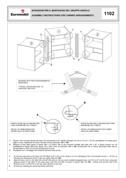
ISTR-40
ASSEMBLING INSTRUCTIONS FOR ISLAND DISPLAY UNITS
1
Traverso
Crosspiece
Fiancata gondola
Side piece for island display unit
1. Collegare con le apposite viti le traverse alle fiancate metalliche gondola.
Per la stabilità della stessa è indispensabile che siano serrate correttamente tutte le 16 viti metriche a disposizione.
Join the crosspieces to the metal side-pieces for island display unit with the screws. For the stability of the island display unit it is necessary to correctly screw all 16 provided metric screws.
ISTR-42
ASSEMBLING INSTRUCTIONS FOR ACCESSORIES INSTALLATION BAR, ISLAND DISPLAY UNIT HEAD
1
2
Fiancata gondola
Side-piece for island display unit
Tassello metallico
Metal dowel
1. Inserire nelle asole i due tasselli metallici.
Insert the two metal dowels in the slots.
2. Infilare la barra aggancio accessori.
Insert the accessories installation bar.
Barra aggancio accessori
Accessories installation bar
ISTR - 43
ASSEMBLING INSTRUCTIONS FOR CABINETS AND GLASS DISPLAY CASES
1
2
3
Piastrino
antiribaltamento
Anti-overturning
plate
Barre appenderia
Hanging bars
Fiancata gondola
Side-piece for island display unit
1. Collegare le barre alle fiancate.
Join the bars to the side-pieces.
2. Posizionare il mobile o la vetrina sulle barre di collegamento, fissarle tramite le apposite viti.
Place the unit or the glass display case on the connecting bars, fix them using the special screws.
3. Completare il montaggio inserendo i piastrini antiribaltamento.
Complete the assembling by inserting the anti-overturning plates.
ISTR-44
ASSEMBLING INSTRUCTIONS FOR WALL SIDE PIECES
1
MODULARITA'
MODULARITY
3
Staffa a parete
Wall stirrup
2,5
2,5
2,5
B
Copristaffa
B
1,25
Stirrup cover
1,25
Fiancata metallica
Metallic side-piece
Interasse
Interspacing
2
B
53,2
78,2
103,2
231,2
153,2
Copripiede
13,6
Foot-cover
1. Fissare le staffe a parete con gli appositi tappi a pressione, posizionandole come indicato in "MODULARITA' ".
Fix the wall stirrups using the pressure cups by placing them as shown in "MODULARITY".
2. Inserire nella fiancata metallica i copristaffa e copripiede in plastica.
Insert the plastic stirrup cover and foot-cover in the metallic side piece.
3. Collegare la fiancata metallica alle staffe precedentemente fissate a parete e dopo averla livellata bloccarla con le apposite viti metriche.
Join the metallic side piece to the stirrups previously fixed to the wall. After having levelled the side piece, fix it with the metric screws.
ISTR-46
ASSEMBLING INSTRUCTIONS FOR HANGING WALL SIDE PIECES
1
MODULARITA'
MODULARITY
2,5
2,5
B
1,25
3
Staffa a parete
2,5
Wall stirrup
B
1,25
Copristaffa
Stirrup cover
Interasse
Fiancata metallica
Interspacing
Metallic side-piece
B
2
53,2
78,2
103,2
X
147,2
153,2
1. Dopo aver definito la posizione della fiancata rispetto al pavimento, fissare le staffe a parete con gli appositi tappi a pressione come indicato in "MODULARITA' ".
After having defined the position of the side piece with respect to the floor, fix the wall stirrups using the pressure cups as shown in "MODULARITY".
2. Inserire nella fiancata metallica i copristaffa in plastica.
Insert the plastic stirrup covers in the metallic side piece.
3. Collegare la fiancata metallica alle staffe precedentemente fissate a parete e bloccarla con le apposite viti metriche.
Join the metallic side piece to the stirrups previously fixed to the wall and fix it with the metric screws.
ISTR-48
ASSEMBLING INSTRUCTIONS FOR VERTICAL FRAME, FLOOR-CEILING
1
MODULARITA'
MODULARITY
2,5
2,5
B
2
Copristaffa
Stirrup cover
3
2,5
B
1,25
Piastrino fissaggio
1,25
Fixing plate
Interasse
Interspacing
Copripiede
B
Montante
Foot cover
Vertical frame
53,2
78,2
Piedino
Foot
(A) = Montante
Vertical frame
ceiling height
153,2
(B) = altezza soffitto
103,2
4
5
Determinazione altezza montante:
Determination of vertical frame height
A = B-3,5 cm
1. Fissare a soffitto la piastra superiore in metallo con l'apposito tappo a pressione.
Fix the upper metal plate to the ceiling with the pressure cap.
2. Inserire nel montante il copripiede e il copristaffa in plastica.
Insert the plastic foot cover and stirrup cover in the vertical frame.
3. Dopo aver avvitato completamente il piedino di regolazione posto nella parte inferiore del montante, inserire lo stesso nella piastra superiore precedentemente fissata a soffitto.
After having completely screwed the adjusting foot placed in the lower part of the vertical frame, insert it in the upper plate, which has been previously fixed to the ceiling.
4. Regolare il piedino in modo che il montante non possa piu' uscire dalla piastra superiore.
Adjust the foot so that the vertical frame does not come out of the upper plate.
5. Dopo aver livellato la parete ottenuta, forare il piedino in plastica e fissarlo a pavimento, questa operazione è resa necessaria per evitare che il montante urtato accidentalmente
possa sganciarsi dalla staffa superiore e rovinare a terra.
After having levelled the obtained wall, drill the plastic foot and fix it to the floor. This operation is necessary in order to keep the vertical frame from releasing from the stirrup and fall down,
when accidentally hit.
ISTR-50
ASSEMBLING INSTRUCTIONS FOR ANTI-OVERTURNING PLATES AND SHELF REINFORCEMENT BARS
1
2
MENSOLE CON BARRE RINFORZO PIANI
BRACKETS WITH SHELF REINFORCEMENT BARS
Ripiani legno
Wood shelves
Piastrino antiribaltamento
Perni in plastica
Anti-overturning plate
Plastic pins
Ripiani vetro
Glass shelves
Ventosa
Suction cup
1. Dopo aver posizionato le mensole metalliche sulle fiancate, inserire se previste le barre di irrigidimento in metallo, bloccandole alle mensole con i perni in plastica.
After having positioned the metal brackets on the side-pieces, insert the metal stiffening bars, if any, locking them to the brackets using the plastic pins.
2. Inserire il piano e bloccarlo alla mensola con i piastrini in dotazione provvisti di doppia foratura "per piani in legno e in vetro". I piastrini si fissano con i perni in plastica.
Insert the shelf and lock it to the bracket with the provided plates. These plates have a double drilling “for wood and glass shelves” and can be fixed using the plastic pins.
ISTR-52
ASSEMBLING INSTRUCTIONS FOR L.150 CABINETS
1
3
2
Mensole metalliche
Metallic brackets
Perni in plastica
Fiancata
Plastic pins
Side-piece
Viti di giunzione
Joining screws
Come specificato nel listino queste
soluzioni si ottengono affiancando
tra loro due mobili lunghi cm.75.
4
5
Anti-overturning plates
As specified on the price list, these
compositions are obtained by placing
side by side two L. 75 cm. cabinets.
Piede centrale
Central foot
1. Posizionare le mensole metalliche sulle fiancate.
Position the metallic brackets on the side-pieces.
2. Inserire alla base dei fianchi dei mobili gli appositi perni in plastica.
Insert the plastic pins at the base of the cabinet side panels.
3. Collegare tra loro i mobili utilizzando le viti di giunzione (poste nel collo piede centrale).
Link the cabinets by using the joining screws (find the joining screws together with the central foot).
4. Appoggiare i mobili collegati tra loro sulle mensole, posizionare il piede metallico sotto il mobile e fissarlo con le viti autofilettanti.
Place the linked cabinets on the brackets, position the metal foot under the cabinet and fix it with the self-tapping screws.
5. Completare il montaggio inserendo i piastrini antiribaltamento.
Complete the assembling by inserting the anti-overturning plates.
Piastrini antiribaltamento
ISTR-54
ASSEMBLING INSTRUCTIONS FOR CABINETS AND GLASS DISPLAY CASES
1
Mobiletto Cabinet
Mensole metalliche
Metallic brackets
3
4
Piastrini antiribaltamento
Anti-overturning plates
Fiancata
Side-piece
2
Perni in plastica
Plastic pins
1. Posizionare le mensole metalliche sulle fiancate.
Place the metallic brackets on the side-pieces.
2. Inserire nei fianchi dei mobili/vetrine gli appositi perni in plastica.
Insert the plastic pins in the cabinets/glass display case side panels.
3. Appoggiare i mobili/vetrine sulle mensole.
Place the cabinets/glass display cases on the brackets.
4. Completare il montaggio inserendo i piastrini antiribaltamento.
Complete the assembling by inserting the anti-overturning plates.
Vetrina Glass display case
ISTR-56
ASSEMBLING INSTRUCTIONS FOR “BOTTONE" INSERTS
3
1
5. Terminale superiore alluminio
Upper aluminium terminal element
4. Inserto
Insert
3. Guida alluminio
Montante
Aluminium guide
Vertical frame
75,5/100,5
75,5/100,5
75,5/100,5
2
2. Pannello "Bottone"
"Bottone" panel
Pannello
Piastrino
Panel
Plate
1. Zoccolo alluminio
Aluminium baseboard
1. Posizionare a parete i montanti per aggancio Retta in corrispondenza dell'unione verticale degli inserti con "Bottone".
Position the vertical frames to the wall for Retta installation in correspondence to the vertical joining of the “Bottone” inserts.
2. Fissare nella faccia interna degli inserti "Bottone" gli appositi piastrini che consentono l'aggancio al montante.
Fix the provided plates in the internal side of the “Bottone” inserts, permitting the installation to the vertical frame.
3. Agganciare prima lo zoccolo ai montanti e poi proseguire con il montaggio dei pannelli e profili come grafico.
Firstly fix the baseboard to the vertical frames and then proceed with the installation of panels and borders as shown in the drawing.
ISTR-58 A
ASSEMBLING INSTRUCTIONS FOR STILO-SPACE GLASS DISPLAY CASES
1
Profilo alluminio
2
Aluminium profile
Fianco in vetro
Glass side panel
Fiancata
Side piece
Cappello
Top shelf
Base
Base
1. Montare i profili di alluminio nei fianchi in vetro.
Insert the aluminium profiles on the glass side panels.
2. Collegare una fiancata alla base e cappello con le apposite viti autofilettanti.
Join one side piece to base and top shelf with the self-tapping screws.
3. Inserire lo schienale, l'altra fiancata e bloccare il tutto con le viti rimaste alla base/cappello.
Insert the back panel, the other side piece and fix everything to the base/top shelf with the remaining screws.
4. Posizionare la vetrina sullo scaffale, fissare la base al mobile inferiore.
Place the glass display case on the upper unit and fix the base to the lower cabinet.
5. Inserire i piani interni, quindi montare le ante.
Insert the inner shelves then assemble the doors.
ISTR-58 B
ASSEMBLING INSTRUCTIONS FOR STILO-SPACE GLASS DISPLAY CASES
3
Schienale
Fiancata
Back panel
Side-piece
5
Ante vetro
Glass doors
Ripiani vetro
Glass shelves
4
a
b
ISTR - 60A
ASSEMBLING INSTRUCTIONS FOR ISLAND DISPLAY UNITS
3
2
1
Telaio base
Base frame
Schienale di testata
Head back panel
Piano base
Base shelf
Telaio base
Base frame
1. Collegare allo schienale il telaio base con le apposite viti.
Join the base frame to the back panel using the provided screws.
2. Collegare lo schienale di testata allo schienale utilizzando i piastrini ad elle e le viti in dotazione.
Join the head back panel to the back panel using the provided L-shaped metal plates and screws.
3. Posizionare il piano base sul telaio base metallico con le apposite viti.
Place the base shelf on the metallic base frame using the provided screws.
ISTR - 60B
ASSEMBLING INSTRUCTIONS FOR ISLAND DISPLAY UNITS WITHOUT BASE
1
A
Schienale di testata
Head back panel
B
1. Collegare: A. la parte superiore dello schienale di testata allo schienale utilizzando i piastrini metallici ad elle in dotazione.
B. la parte inferiore dello schienale di testata allo schienale tramite piastrini rondelle e viti.
Join: A: the upper part of the head back panel to the back panel by using the provided L-shaped metallic plate
B: the lower part of the head back panel to the back panel by using plates, washers, and screws.
Scaricare