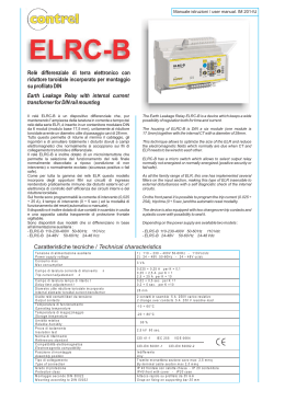
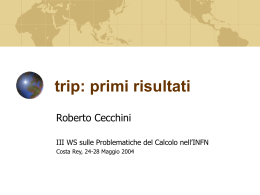
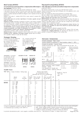
WE PROTECT YOUR
SYSTEM
The Lock-Out Relay plays an important role in the most crucial
utility applications, in an emergency, the Lock-Out Relay perfomances
can spell the difference between a routine outage and the destruction
of very expensive equipments.
The COMELETRIC Lock-Out Relays protects your system
and your personnel.
Il Relè di Blocco gioca un ruolo di cruciale importanza nelle applicazioni
più critiche , durante un' emergenza esso fa la differenza tra un' ordinaria
anomalia e la distruzione di apparecchiature molto costose.
I Relè di Blocco COMELETRIC proteggono il vostro
sistema ed il vostro personale.
The Lock-Out Relays are high-speed control Relays used as auxiliary
Relays in applications requiring many contacts (up 24).
They are generally used in conjunction with differential relays to protect
Circuit Breakers , Transformers , Buses and Rotating Machinery
in various electrical systems.
I relè di blocco sono relè ad alta velocità e vengono utilizzati come relè ausiliari in
applicazioni che richiedono numerosi contatti (fino 24).
Essi sono generalmente utilizzati in combinazione con relè differenziali per proteggere
Interruttori , Trasformatori, e Macchine Rotanti
nei vari sistemi elettrici
When a failure occurs , the Lock-Out Relay intervenes tripping
the contacts and locking the system.
All the critical circuits will be isolated and will remain isolated until
the malfunction is solved.
Its positive trip action ensures that all the contacts would perform as to
requirements and its multi-contacts arrangements eliminate the need for
several control relay contacts.
Se dovesse verificarsi un guasto, il Relè di Blocco si aprirà e bloccherà il
sistema, assicurando che tutti i circuiti critici siano isolati e resteranno
isolati fino a quando il guasto non verrà eliminato.
La sua apertura ad azione positiva assicura che tutti i contatti
si comportino allo stesso modo ed i suoi contatti multipli eliminano la
necessità di una serie di contatti a relè di comando.
.
www.comeletric.it
1
PRINCIPLE OF OPERATION:
The Lock-Out Relay doesn't need any special wiring for its operation.
It needs only a N.O. (FC) contact for controlling the coil in TRIP position.
The Lock-Out Relay is activated by turning the knob from the TRIP position to the RESET position:
once in the RESET position the knob is blocked and can no longer be manually
reset in the TRIP position.
The Lock-out Relay contact LR, which is in series with the Lock-out Relay coil,
will be closed at the RESET position only.
The fault contact FC makes only when there is a fault in the circuit.
When the Lock-out Relay coil LR is energized, it will release the mechanical latch holding
the handle at RESET position and the handle will spring return to TRIP position.
So long as FC remains at close contact condition (due to the presence of a fault in the circuit) the
handle will not latch at RESET position but will always spring return to TRIP.
Il relè di blocco non richiede alcun cablaggio speciale per il suo funzionamento.
Esso richiede solo un contatto N.O. (FC) per comandare l'elettromagnete e far
scattare il relè in posizione TRIP .
Il relè di blocco viene armato ruotando la manopola da posizione di TRIP a
posizione di RESET, una volta in posizione di RESET la
manopola viene bloccata e non può essere riportata manualmente
in posizione di TRIP.
Il contatto LR, in serie con la bobina del relè, chiude solo nella posizione RESET.
Il contatto FC si attua solo quando vi è un guasto nel circuito.
Quando la bobina LR del relè di blocco viene eccitata, viene rilasciato il fermo meccanico che tiene la
leva in posizione RESET e la manopola ritorna in posizione TRIP grazie ad una molla.
Finché FC resta in condizione di contatto chiuso (per la presenza di un guasto nel circuito) la
manopola non si bloccherà in posizione RESET ma tornerà automaticamente in posizione TRIP.
TRIP
RESET
+
TRIP
+
FC
L1
LR
LR
LR
LR
Coil
Unit
L2
-
2
FC
L1
LR
RESET
+
FC
L1
Coil
Unit
TRIP
RESET
LR
Coil
Unit
L2
-
NO FAULT CONDICTION.
Handle in TRIP position
Contacts LR and FC open.
NO FAULT CONDICTION.
Handle in RESET position
Contact LR closed and contact FC open.
NESSUNA ANOMALIA NEL SISTEMA
Manopola in posizione TRIP
Contatti LR e FC aperti.
NESSUNA ANOMALIA NEL SISTEMA
Manopola in posizione RESET
Contatto LR chiuso e contatto FC aperto.
L2
FAULT CONDICTION.
Handle Spring return in TRIP position
Contact LR open and contact FC close won't possible restore
the LOR in RESET position until the contact FC will be close.
ANOMALIA NEL SISTEMA
Manopola ritorna automaticamente in posizione TRIP
Contatto LR aperto ed il contatto FC chiuso , non sarà possibile
riposizionare il relè in posizione RESET finchè il contatto FC resterà
chiuso.
www.comeletric.it
ELECTROMAGNET DATAS:
The Comeletric Lock-out Relays are Direct Current actuated auxiliary relays.
The coil circuit is interrupted by one of the contacts of the said relays as soon as the manoeuvre
is performed. They may be subjected to maximum design voltage without exceeding 55°
temperature ambient conditions.
I relè di blocco Comeletric sono relé ausiliari azionati in Corrente Continua.
Il circuito della bobina viene interrotto da uno dei contatti di detti relè non appena viene eseguita la
manovra. Essi possono essere sottoposti alla tensione massima prevista, senza però superare la
temperatura massima di 55 ° C.
Type n°
Tipo n°
Coil Nominal
Voltage
Alimentazione
Volt.
Coil
Resistance @ 20°C
Resistenza
Avvolgimento@ 20°C
Burden
Ampere (DC)
Corrente
Assorbita (CC)
Power
(W)
Potenza
(W)
Operating
Range
Range di
Utilizzo
1330/24
24 Vdc
3.33 Ω
7.20
174
20 to 28 Vdc
1330/48
48 Vdc
10.85 Ω
4.42
212
38.4 to 52.8 Vdc
1330/110
110 Vdc
55 Ω
2
220
88 to 121 Vdc
1330/125
125 Vdc
62.3 Ω
2
250
100 to 137.5 Vdc
1330/220
220 Vdc
217 Ω
1.01
224
176 to 242 Vdc
+
ADDITIONAL INFORMATION.
In selecting the coil voltage of the Lockout Relay, it is important to
verify if additional coils e.g. protective relays coils etc, will be connected
in series with the Lock-out Relay coil.
In order to ensure that the Lock-out Relay could trip if a fault should
occurs,it is important:
· To adjust the setting of the protective relay TS1 coil so that the
Lock-out Relay could trip when the coil is energized.
· If the protective relay coil is not adjustable, it is important that the
coil voltage of the Lock-out Relay is properly selected to match with
the series coil TS1 so that the Lock-out Relay coil trips when
energized.
Nel selezionare la tensione della bobina del relè di blocco, è importante
verificare se la bobina aggiuntiva, ad es. le bobine del relè di protezione,
sia collegata in serie con la bobina del Relé di blocco.
Al fine di garantire il normale utilizzo del Relé di blocco in caso di
guasto,è importante:
· Regolare l' impostazione della bobina del relè di protezione TS1,
in modo tale che il relé si sblocchi quando la bobina è eccitata.
· Se la bobina del relé di protezione non è regolabile, è importante che
la tensione della bobina del relé sia correttamente selezionata in
funzione del valore della bobina della serie TS1, in modo che il
relé di blocco si ecciti regolarmente.
DC Trip Bus
FC
L1
V1
LR
LR
Coil
Unit
L2
Without Series Relay Coil.
Senza Bobina in Serie.
DC Trip Bus
+
FC
V2
Protective Relay Coil
Bobina del Relè di
protezione
TS1
L1
LR
V1
LR
Coil
Unit
L2
With Series Relay Coil.
Con Bobina in serie.
www.comeletric.it
3
RESPONSE IN TIME:
To obtain the maximum tripping speed, the Lock-out Relay coils are rated for intermittent duty only.
Continuous energization of the coil may overheat the coil.
Per ottenere la massima velocità di intervento, le bobine Relé di Blocco sono tarate solo per servizio
intermittente. Ciò determina che l’ eccitazione continua della bobina possa causarne il surriscaldamento.
TRIP MECHANICAL INDICATOR:
The trip mechanical indicator is an optical indicator to show the TRIP/RESET that the handle
has been turned to. Hence , when the handle is turned and remain latched at RESET
position, the trip indicator shows GREEN on the window of the frontplate.
If a fault condiction arises, the handle will turn to TRIP position and the
indicator will show RED on the window.
L'indicatore meccanico è un indicatore visivo per mostrare in quale posizione, TRIP / RESET la maniglia
sia stata ruotata. Quindi, quando la maniglia è ruotata e bloccata in posizione di RESET,
l'indicatore mostra il colore VERDE sulla finestra del frontalino.
In condizione di guasto, la maniglia ruoterà automaticamente in posizione di TRIP, conseguentemente
l’ indicatore mostrerà il colore ROSSO sulla finestra.
4
www.comeletric.it
MECHANICAL CHARACTERISTICS:
The contact packet of the Lockout Relays is the
same used in R20 and FR10 control switches series.
Il pacco contatti dei relé di blocco, è lo stesso
utilizzato negli interruttori di comando della serie R20 ed FR10 .
Contact system with self-cleaning action
on both sides of contact, suitable for
being used in highly aggressive environments,
with presence of high percentage of saline dust
and corrosive agents
Sistema contatto strisciante con effetto autopulente
su entrambe le superfici di contatto, particolarmente
idonei ad essere utilizzati in ambienti altamente aggressivi ,
presenza di polvere, alto tasso salino ecc....
The contacts are thickly silver (standard) or gold plated on
request.
Double bridge Rotor contact Knife type Fixed contacts
with self-cleaning effect.
Contatto mobile a doppio ponte contatti fissi a coltello
con effetto strisciante autopulente.
Contatti argentati (Standard) o dorati su richiesta.
Contacts design bounce-proof , this makes it ideal for high speed quick break design
like the Lockout Relays.
Design dei contatti a prova di rimbalzo, questo lo rende ideale per la applicazione di
apertura ad alta velocità come nel caso dei relé di blocco.
Mechanism with spring stainless steel double torsion,
It is driven directly from the shaft control.
One of the plates of the relay acts as a mechanical stop
when the relay is triggered by TRIP RESET position.
Meccanismo di scatto con molla in acciaio inox a doppia
torsione , Essa viene trascinata direttamente dall’ albero
di comando . Una delle piastre del relè agisce da fermo
meccanico quando il relè scatta da posizione RESET a TRIP.
High mechanical strength, shaft and main structure in zinc
plated steel, suitable for tropical climates.
Elevata robustezza meccanica, albero e struttura portante
interamente in acciaio zincato elettroliticamente, idoneo ad
essere montato anche in zone tropicali.
Lock-Out Relay Trip
Mechanisme.
Meccanismo di Scatto del
Relè di Blocco.
High resistance to shock and vibration, due to the clip and blade contact design.
Elevata resistenza a Shock e Vibrazioni. Poiché il contatto fisso è posizionato tra le
due lame , il contatto viene premuto su una lama nel caso la forza sull'altra diminuisca.
High resistance to shock and vibration, due to the clip and blade contact design.
I contatti sono comandati direttamente dall'albero di comando, quindi i contatti sono
simultanei.
www.comeletric.it
5
HOW TO ORDER:
Product Coding
LR102
-
1
_
2
-
+ S Q 7 - 2
3
4
5
6
1 Model Number of the Lockout Relay.
N° di Modello del Relè di Blocco.
Model number means the assembly and the construction form unique for each Lockout Relay, this identifies the series and the type of
Lockout relay. This model number is indicated in the catalogue along with its dimensional drawing and panel cutout.
Come n° di modello si intende il montaggio e la forma costruttiva univoca di ogni singolo Relé di blocco, questo riferimento identifica la
serie ed il tipo di Relé di blocco. Questo n° di modello viene indicato nel catalogo insieme al relativo disegno di ingombro e della foratura
del pannello.
2 Contact configuration (electric diagram).
Configurazione contatti (schema elettrico).
One Packet
This number is an indication of the electric diagram of the Lockout Relay required.
The number of packets affects the number of poles required; in each packet we have a contact NORMALLY OPEN and a
contact NORMALLY CLOSED, next to the table of lengths , it is shown the maximum number of packets suitable for that
specific model number.
Questo numero è un’ indicazione dello schema elettrico del relé di blocco desiderato.
Il numero di pacchetti influisce sul numero dei poli; in ogni pacchetto abbiamo un contatto NORMALMENTE APERTO ed uno
NORMALMENTE CHIUSO, accanto alla tabella delle lunghezze, è indicato il numero massimo di pacchetti realizzabile per tale
specifico numero di modello.
1
1
3
x
2
4
x
3 Voltage of the tripping Coil.
Voltaggio della bobina di sgancio.
01 = 24 Vdc
04 = 125 Vdc
02 = 48 Vdc
05 = 220 Vdc
03 = 110 Vdc
01A= 24 Vca (with external rectifier)
(con raddrizzatore esterno)
02A = 48 Vca (with external rectifier)
(con raddrizzatore esterno)
03A = 110 Vca (with external rectifier)
(con raddrizzatore esterno)
04A = 125 Vca (with external rectifier)
(con raddrizzatore esterno)
05A = 220 Vca (with external rectifier)
(con raddrizzatore esterno)
4 Trip mechanical indicator required.
Indicatore meccanico colorato.
The letter "S" before the type of the front plate indicates the need for the mechanical indicator.
La lettera "S" prima della tipologia della mostrina frontale indica la necessità dell'indicatore meccanico colorato.
5 n° Look.
N° di Look.
This number identifies the colour of the front side of the LOR (see page 11).
Questo numero identifica il colore della parte frontale del Relè di blocco (vedi pag. 11).
6 n° Engraving of the frontplate.
N° di Incisione della Mostrina.
This number identifies the desired text of the frontplate.
Questo numero identifica l'incisione della mostrina desiderata.
6
www.comeletric.it
Series LR20
LOCKOUT RELAY 86
Model : LR102 Standard Oval Handle
LR102W Wing Handle
LR102P Pistol grip Handle
* Self Cleaning contact systems.
* Terminals with IP20 finger proof protection (IEC 60529).
* High Mechanical Reliability.
* Rear access Screw Terminals.
* Trips coil from 24Vdc up to 220Vdc.
* Contatti con Sistema Autopulente.
* Terminali con protezione IP20 (IEC 60529).
* Alta affidabilità Meccanica.
* Facilità di accesso al morsetto dal retro del Relè.
* Elettromagneti da 24Vdc fino a 220Vdc.
Dimensions
2:4
71
62
127.5
61
64
Panel Drilling
.5
48
Ø4
X
48
Ø12
N° PACKETS
N° PACCHI
1
2
X=LENGHT mm
LUNGH mm
83
95 107 119 131 143 155 167 179 191 203 215
3
4
5
6
7
8
9 10 11 12
RATED ELECTRICAL CHARATERISTICS
CARATTERISTICHE ELETTRICHE NOMINALI
According to standards
Conformità alle norme
IEC 60947-3 - IEC 60947-5-1 - IEC 60947-1 - CEI EN 60947-3 – CEI EN 60947-5-1 - CEI EN 60947-1,
2006/95/EC (Low Voltage Directive) , 2004/108/EC (EMC Directive) , 2011/65/EU (ROHS Directive).
MAKING AND BREAKING CAPACITIES
POTERI DI CHIUSURA ED INTERRUZIONE
Conventional free air thermal current
Corrente convenzionale termica in aria
(Ith)
25 A
Rated insulation voltage
Tensione di isolamento nominale :
(Ui)
690 V
Utilization Category
Categoria di utilizzazione
( Ue )
( Ie )
4 KV
AC 14
400 V
16 A
AC 15
400 V
10 A
AC 22A ( 3 Phase - 3 Poli )
415 V
25 A
AC 23A ( 3 Phase - 3 Poli )
415 V
20 A
DC13
220 V
6A
DC14
DC21A
110 V
250 V
220 V
6A
2.5 A
16 A
DC23A
220 V
6A
Rated impulse withstand voltage
Tensione di tenuta ad impulso nominale:
(Uimp)
Frequenza di impiego
Frequency:
50/60 Hz
Relevant information about the associated Short Circuit Protective Device
Dati relativi al dispositivo di protezione contro il corto circuito associabile
Rated conditional short-circuit current ( Max Peak current )
Massima Corrente di picco ammissibile
1550 A
Rated Maximum Joule integral
Integrale di Joule massimo
38 kA² s
Rated Short-time current
(1s)
Corrente nominale di breve durata
Contact Resistance
Resistenza di contatto
(Icw)
300 A
2.5 mΩ
7
Series FRB10
LOCKOUT RELAY 86
Model : LA102 Standard Oval Handle
LA102W Wing Handle
LA102P Pistol grip Handle
* Self Cleaning contacts sytems.
* Terminals suitable for Ring type Terminals.
* High Mechanical Reability.
* Compact design in depth
* Trips coil from 24Vdc up to 220Vdc.
* Contatti con Sistema Autopulente.
* Terminali idonei ad accogliere Occhielli.
* Alta affidabilità meccanica.
* Design compatto in profondità.
* Elettromagneti da 24Vdc fino a 220Vdc.
Dimensions
71
2:4
62
64
127.5
60
8
Panel Drilling
48
Ø4
.5
X
48
Ø12
N° PACKETS
N° PACCHI
1
2
X=LENGHT mm
LUNGH mm
85
93 101 109 117 125 133 141 149 157 165 173
3
5
4
6
7
9 10 11 12
8
RATED ELECTRICAL CHARATERISTICS
CARATTERISTICHE ELETTRICHE NOMINALI
According to standards
Conformità alle norme
IEC 60947-5-1 - IEC 60947-1 - CEI EN 60947-5-1 - CEI EN 60947-1,
2006/95/EC (Low Voltage Directive) , 2004/108/EC (EMC Directive) , 2011/65/EU (ROHS Directive).
MAKING AND BREAKING CAPACITIES
POTERI DI CHIUSURA ED INTERRUZIONE
Conventional free air thermal current
Corrente convenzionale termica in aria
(Ith)
20 A
Rated insulation voltage
Tensione di isolamento nominale :
(Ui)
690 V
Utilization Category
Categoria di utilizzazione
( Ue )
( Ie )
4 KV
AC 14
400V
16A
AC 15
400V
10A
DC13
220V
6A
DC14
110V
250V
6A
2.5A
Rated impulse withstand voltage
Tensione di tenuta ad impulso nominale:
(Uimp)
Frequenza di impiego
Frequency:
50/60 Hz
Relevant information about the associated Short Circuit Protective Device
Dati relativi al dispositivo di protezione contro il corto circuito associabile
Rated conditional short-circuit current ( Max Peak current )
Massima Corrente di picco ammissibile
1550 A
Rated Maximum Joule integral
Integrale di Joule massimo
38 kA² s
Rated Short-time current
(1s)
Corrente nominale di breve durata
Contact Resistance
Resistenza di contatto
8
(Icw)
200 A
2.5 mΩ
www.comeletric.it
CONTACTS CONFIGURATION:
1 NO contact and 1 NC contact
1 Contatto NA ed 1 contatto NC
201_02
Diagram:
Schema:
202_02
PACKETS
1 2
CONTACTS
1 2
CONTACTS
1 2 5 6
ENGRAVINGS
3 4
ENGRAVINGS
3 4 7 8
POSITIONS
1
1
2
1
2
TRIP
RESET
3 NO contacts and 3 NC contacts
3 Contatti NA ed 3 contatti NC
203_02
Diagram:
Schema:
PACKETS
1 2 3
PACKETS
1 2 3 4
CONTACTS
1 2 5 6 9 10
CONTACTS
1 2 5 6 9 10 13 14
ENGRAVINGS
3 4 7 8 11 12
ENGRAVINGS
3 4 7 8 11 12 15 16
1
2
TRIP
RESET
205_02
5 NO contacts and 5 NC contacts
5 Contatti NA ed 5 contatti NC
Diagram:
Schema:
1
2
206_02
6 NO contacts and 6 NC contacts
6 Contatti NA ed 6 contatti NC
PACKETS
1 2 3 4 5 6
CONTACTS
1 2 5 6 9 10 13 14 17 18
CONTACTS
1 2 5 6 9 10 13 14 17 18 21 22
ENGRAVINGS
3 4 7 8 11 12 15 16 19 20
ENGRAVINGS
3 4 7 8 11 12 15 16 19 20 23 24
POSITIONS
1 2 3 4 5
1
2
TRIP
RESET
207_02
7 NO contacts and 7 NC contacts
7 Contatti NA ed 7 contatti NC
Diagram:
Schema:
TRIP
RESET
208_02
8 NO contacts and 8 NC contacts
8 Contatti NA ed 8 contatti NC
1 2 3 4 5 6 7
PACKETS
1 2 3 4 5 6 7 8
CONTACTS
1 2 5 6 9 10 13 14 17 18 21 22 25 26
CONTACTS
1 2 5 6 9 10 13 14 17 18 21 22 25 26 29 30
ENGRAVINGS
3 4 7 8 11 12 15 16 19 20 23 24 27 28
ENGRAVINGS
3 4 7 8 11 12 15 16 19 20 23 24 27 28 31 32
POSITIONS
PACKETS
POSITIONS
Diagram:
Schema:
TRIP
RESET
PACKETS
POSITIONS
1
2
4 NO contacts and 4 NC contacts
4 Contatti NA ed 4 contatti NC
POSITIONS
1
2
Diagram:
Schema:
TRIP
RESET
204_02
POSITIONS
Diagram:
Schema:
2 NO contacts and 2 NC contacts
2 Contatti NA ed 2 contatti NC
PACKETS
POSITIONS
Diagram:
Schema:
TRIP
RESET
www.comeletric.it
1
2
TRIP
RESET
9
209_02
9 NO contacts and 9 NC contacts
9 Contatti NA ed 9 contatti NC
PACKETS
1 2 3 4 5 6 7 8 9
CONTACTS
1 2 5 6 9 10 13 14 17 18 21 22 25 26 29 30 33 34
ENGRAVINGS
3 4 7 8 11 12 15 16 19 20 23 24 27 28 31 32 35 36
POSITIONS
Diagram:
Schema:
1
2
210_02
10 NO contacts and 10 NC contacts
10 Contatti NA ed 10 contatti NC
PACKETS
1 2 3 4 5 6 7 8 9 10
CONTACTS
1 2 5 6 9 10 13 14 17 18 21 22 25 26 29 30 33 34 37 38
ENGRAVINGS
3 4 7 8 11 12 15 16 19 20 23 24 27 28 31 32 35 36 39 40
POSITIONS
Diagram:
Schema:
TRIP
RESET
1
2
211_02
11 NO contacts and 11 NC contacts
11 Contatti NA ed 11 contatti NC
PACKETS
1 2 3 4 5 6 7 8 9 10 11
CONTACTS
1 2 5 6 9 10 13 14 17 18 21 22 25 26 29 30 33 34 37 38 41 42
ENGRAVINGS
3 4 7 8 11 12 15 16 19 20 23 24 27 28 31 32 35 36 39 40 43 44
POSITIONS
Diagram:
Schema:
TRIP
RESET
1
2
212_02
12 NO contacts and 12 NC contacts
12 Contatti NA ed 12 contatti NC
PACKETS
1 2 3 4 5 6 7 8 9 10 11 12
CONTACTS
1 2 5 6 9 10 13 14 17 18 21 22 25 26 29 30 33 34 37 38 41 42 45 46
ENGRAVINGS
3 4 7 8 11 12 15 16 19 20 23 24 27 28 31 32 35 36 39 40 43 44 47 48
POSITIONS
Diagram:
Schema:
TRIP
RESET
1
2
10
TRIP
RESET
www.comeletric.it
STANDARD FRONTPLATE ENGRAVING:
0
1
20003
BLOCK
SERVICE
20705
GESPERRT
SERVICE
20706
LOCKOUT
TRIP
SERVICE
20363
BLOCCO
20199
SERVIZIO
BLOCCO
20710
TRIP
RESET
SBLOCCO
TRIP
20553
EN
SERVICE
LOCKOUT
20703
20701
NORMAL
BLOQUE'
ABIERTO
RESTABLECER
20197
BLOQUEADO
20702
0
20708
BLOCAT
SERVICIU
RESET
SERVICIO
20704
БЛОК
20707
СЕРВИС
20709
HANDLE AND FRONTPLATE COLOUR:
The font used for the text is SWISS 921 BT.
The dimension of letters are proportioned to the dimension text.
Il font usato per il testo è SWISS 921 BT.
Le dimensioni delle lettere sono proporzionate alle dimensioni del testo totale.
LOOK N°
L1
L2
L3
L4
L5
L6
L7
L8
L9
L10
www.comeletric.it
Handle
BLACK
RED
RED
BLACK
RED
WHITE
RED
BLACK
BLACK
BLACK
RED
Frontplate
BLACK
YELLOW
BLACK
YELLOW
RED
BLACK
ELECTRO GREY
ELECTRO GREY
GREEN
WHITE
WHITE
Holder
BLACK
BLACK
BLACK
BLACK
RED
BLACK
BLACK
BLACK
BLACK
BLACK
BLACK
Text
WHITE
BLACK
WHITE
BLACK
WHITE
WHITE
BLACK
BLACK
WHITE
BLACK
BLACK
11
COMELETRIC ACCESSORIES AND SPARE PARTS:
WING HANDLES
PART NUMBER
1500
Knob Wing Type.
Knob in fiberglass reinforced technopolymer.
COLOUR
BLACK
1500/R
RED
1500/G
GREY
Manopola a vela.
Manopola in Tecnopolimero caricato fibra vetro.
PISTOL GRIP HANDLE
PART NUMBER
1572
Pistol Grip Handle.
Knob in fiberglass reinforced technopolymer, its particular
shape ensures a secure grip even with the use of gloves.
Manopola a Pistola.
Manopola in tecnopolimero caricato con fibra di vetro.
Il suo design permette un impugnatura sicura anche con
l'utilizzo di guanti.
TRIP COIL
In case of burning the coil, it may be easily replaced
from the rear of the relay. The access to the
mounting screws is located on the back plate.
In caso di bruciatura la bobina può essere facilmente
sostituita dal retro del relé.
L'accesso alle viti di fissaggio è posto sul retro piastra.
RECTIFIER
COLOUR
BLACK
1572/R
RED
1572/G
GREY
PART NUMBER
VOLTAGE
1330/24
24Vdc
1330/48
48Vdc
1330/110
110Vdc
1330/125
125Vdc
1330/220
220Vdc
PART NUMBER
RAD1
Rectifier is used when the application of Lockout relay
is Alternating Current. It is generally mounted in place of
the terminal. Faston terminals 5mm.
Il raddrizzatore viene utilizzato quando l'applicazione del
relé di blocco è in Corrente Alternata.
Esso viene montato generalmente al posto del morsetto.
Terminali tipo faston 5mm.
TERMINAL BLOCK
PART NUMBER
Bm9517
Terminal Block support in melamine.
One terminal is connected to a terminal of the coil, while the
other is connected to a relay contact to allow the
immediate stoppage of coil after the release operation.
Morsetto di appoggio in melamina.
Esso viene collegato ad un terminale della bobina di
sgancio , mentre l'altro terminale viene collegato ad un contatto del relé per
permettere l'interruzione istantanea della bobina dopo l'operazione di sgangio.
12
www.comeletric.it
TESTING:
COLLAUDI:
To ensure the constant quality of its products, COMELETRIC pays particular attention to its incoming materials and
performs systematic inspections of each production phase. At the end of the production process the switches
are subjected to mechanical and electrical testing before being sealed.
A garanzia costante della qualità dei suoi prodotti, COMELETRIC presta particolare attenzione ai materiali in
ingresso ed effettua sistematici controlli di ogni step produttivo. Al termine del processo produttivo i commutatori
vengono sottoposti a collaudo sia meccanico che elettrico e successivamente sigillati.
THE COMPANY:
L'AZIENDA:
COMELETRIC has based production around its quality control system, configured in conformity with the
UNI EN ISO 9001:2008 standard and certified since July 2004. The design process, also subject to the
quality control system, not only makes it possible to satisfy even the most specialized requirements
of clients, but also to manage the production parameters and thus ensure that the quality
of the products is maintained.
COMELETRIC opera basandosi sul proprio
sistema di gestione per la qualità , costruito in conformità alla norma UNI EN ISO 9001:2008
e certificato fin dal luglio 2004. Il processo di progettazione anch' esso
compreso nel sistema di gestione per la qualità , permette non solo di soddisfare le esigenze
più specialistiche dei clienti , ma anche di gestire i parametri della produzione in modo da garantire
nel tempo il mantenimento del livello qualitativo dei prodotti.
EXTERNAL TESTING AND APPROVALS:
COLLAUDI ESTERNI ED OMOLOGAZIONI:
COMELETRIC switches have been subjected to extensive testing at the most highly accredited
national laboratories such as CESI, INRIM (Istituto Elettrotecnico Nazionale) "Galileo Ferraris".
These tests have been conducted in compliance with IEC 60947-1, IEC 60947-3, IEC 60947-5-1,
CEI EN 60947-1, CEI EN 60947-3, CEI EN 60947-5-1 legislation
(Control circuit-devices and switching elements).
I commutatori COMELETRIC sono stati sottoposti a numerose prove presso i più accreditati
laboratori nazionali come CESI , INRIM (Istituto Elettrotecnico Nazionale) “Galileo Ferraris”.
Tali test sono stati eseguiti in conformità alla normativa IEC 60947-1, IEC 60947-3, IEC 60947-5-1,
CEI EN 60947-1, CEI EN 60947-3, CEI EN 60947-5-1.
(Dispositivi per circuiti di comando ed elementi di manovra).
www.comeletric.it
13
Scaricare