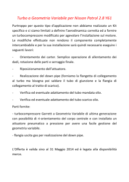
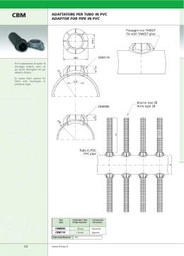
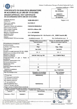
INDICE: TABLE OF CONTENT: 1. Introduzione pag. 3 1. Introduction 2. Descrizione del sistema pag. 4 2. System Description pag. pag. pag. 4 5 6 3. Applicazioni pag. 7 3. Applications 4. Caratteristiche dei componenti pag. 8 4. Components specification pag. pag. 8 8 pag. 9 pag. pag. pag. pag. pag. 9 12 13 15 17 2.1 Componenti del sistema CUNIPRESS 2.2 Unione di tubi e raccordi 2.3 Attrezzatura per l’accoppiamento 4.1 Caratteristiche chimiche e meccaniche 4.2 Metodo di fabbricazione 5. Dati tecnici per la progettazione 5.1 5.2 5.3 5.4 5.5 Perdite di carico Velocità di flusso Dilatazione termica Assorbimento delle dilatazioni termiche Fissaggio dei tubi 6. Istruzioni per l’installazione 6.1 6.2 6.3 6.4 Taglio dei tubi Curvatura dei tubi Giunzione dei tubi Accoppiamento con accessori filettati o flangiati 7. Programma di fornitura - 2.1 CUNIPRESS System components 2.2 Connection of pipes to the fittings 2.3 Tools for coupling 4.1 Chemical and mechanical properties 4.2 Manufacturing 5. Technical data for design 5.1 5.2 5.3 5.4 5.5 6. Installation guideline pag. 19 pag. pag. pag. pag. Pressure drops Flow Velocity Thermal expansion Compensation of thermal expansion Pipe fixing 6.1 6.2 6.3 6.4 19 19 19 21 Pipe cutting Pipe bending Pipe coupling Coupling with threaded or flanged fittings 7. Supply program pag. 22 - I dati contenuti in questo catalogo compresi la forma, le dimensioni ed i pesi dei materiali descritti non devono ritenersi vincolanti. La Società produttrice del sistema CUNIPRESS si riserva infatti di apportare in qualunque momento modifiche per ragioni di natura sia tecnica che commerciale, senza che ciò costituisca valida giustificazione per reclami da parte del committente. The information in this catalogue - i.e data, shapes, dimensions of the items - is not binding. The manufacturer of CUNIPRESS System reserve themselves the right to howsoever modify same because of technical as well as commercial reasons without entitling any buyer to whatsoever complaint. 2 CUNIPRESS 1. Introduction 1. Introduzione Il sistema brevettato CUNIPRESS consente di realizzare in The patented CUNIPRESS System has been studied to modo affidabile e conveniente le tubazioni di tutti gli impianti realize in a reliable and economic way pipeworks for sea- con acqua di mare, salmastra ed industriale in genere nel water, brackish water and industrial water in the range of campo dei diametri da 15 a 108 mm. diameters from 15 up to 108 mm. Il sistema CUNIPRESS è costituito dai seguenti compo- The CUNIPRESS System consists of the following nenti: components: - - - - Raccordi Fittings curve, tee, riduzioni, etc. in cupronichel 90/10 conforme bends, T pieces, reducers, etc. in 90/10 copper-nickel alla specifica americana UNS C 70600 alloy according to UNS C 70600 USA standard - Tubi Pipes trafilati a freddo di precisione in cupronichel 90/10 con precision cold-drawn in 90/10 copper-nickel alloy accor- forme alla specifica americana UNS C 70600 ding to UNS C 70600 USA standard - Pinza elettromeccanica / elettroidraulica Electromechanical / electrohydraulic pressing tools per la giunzione mediante compressione dei raccordi al for the connection of components by pressing the tubo fittings onto the pipe ends Il programma di fornitura è completato da accessori ac- The range of component is completed with accessories which coppiabili ai tubi con la stessa tecnologia dei raccordi can be coupled to the pipe with the same technique of CUNIPRESS. CUNIPRESS fittings. Principali vantaggi del Sistema CUNIPRESS Main advantages of CUNIPRESS System - semplicità e rapidità di montaggio - Simple and fast assembly - affidabilità anche in severe condizioni di utilizzo - Reliability of pipework also in severe service conditions - elevata resistenza dell’impianto alle corrosioni in acque di - High corrosion resistance of piping for sea, brackish and industrial water services mare, salmastra ed industriali in genere - Elimination of workshop labour normally carried out - eliminazione delle fasi di lavorazione dei tubi in officina with conventional systems normalmente eseguite con i sistemi tradizionali 3 2. Descrizione del Sistema 2. System Description Componenti del Sistema CUNIPRESS 2.1 CUNIPRESS System components 2.1 Gli elementi di base del Sistema sono gli speciali raccordi The basic elements of the System are the specially designed CUNIPRESS in cupronichel 90/10 che, disponibili in varie CUNIPRESS fittings in 90/10 copper-nickel in various tipologie e dimensioni (vedi programma di fornitura da pag. forms and dimensions (see range of manufacture from page 22 a pag. 46) consentono di realizzare le reti di distribuzione 22 to page 46) that allow to install distribution systems using utilizzando solo raccordi e tubi in verghe. fittings and straight pipes only. I raccordi hanno ad ogni estremità una camera toroidale nella Fittings have at each end a toroidal groove with an o-ring seal, quale è inserito un o-ring in gomma sintetica che una volta in synthetic rubber, which deformed by a pressing tool deformato dall’azione di pressatura della pinza realizza la provides the tightness to the coupling. tenuta ermetica in accoppiamento con il tubo. La tenuta meccanica è invece garantita dalla deformazione The mechanical strength is ensured by the deformation of congiunta del raccordo e del tubo in esso innestato. fitting and inserted pipe. Usando gli appositi raccordi misti è possibile collegare inoltre Using suitable adaptor fittings, systems realized in gli impianti realizzati con il sistema CUNIPRESS anche ad CUNIPRESS elementi flangiati o filettati. flanged standard elements. Il secondo elemento del Sistema è costituito dai tubi The second element of the System are the cold drawn CUNIPRESS can be combined also with threaded or CUNIPRESS pipes in 90/10 copper-nickel material sup- in cupronichel 90/10 trafilati a freddo che vengono forniti allo stato ricotto in verghe di lunghezza di 6 plied in annealed condition and in lengths of 6 meters. metri. La serie di diametri e di spessori disponibili è la seguente: Diametro esterno mm The range of pipe dimensions is the following: spessore mm Outside diameter mm Thickness mm 15 1 15 1 18 1 18 1 22 1 22 1 28 1,5 28 1,5 35 1,5 35 1,5 42 1,5 42 1,5 54 1,5 54 1,5 76,1 2 76,1 2 88,9 2 88,9 2 108 2,5 108 2,5 Per garantire una tenuta ottimale in tutte le condizioni di In order to guarantee a perfect tightness of the system in all impiego i tubi hanno una tolleranza dimensionale sul diametro service conditions, pipes have a tolerance on the outside esterno nei limiti precisati dalle norme ASTM B 466 M. diameter within the limits specified in ASTM B 466 M standard. L’o-ring di tenuta è realizzato in uno speciale elastomero The o-ring seal is made from a special elastomeric material particolarmente resistente all’invecchiamento, all’acqua di highly resistant to ageing, sea-water, hot and cold water (also mare, all’acqua dolce calda e fredda (anche in presenza degli when treated with the additives normally used for drinking additivi normalmente impiegati per l’acqua potabile) . water). 4 CUNIPRESS 2.2 Unione di tubi e raccordi 2.2 Connection of pipes to the fittings Al fine di ottenere l’accoppiamento, il tubo viene inserito nel To make the connection, the pipe is inserted into the fitting raccordo fino alla battuta. until it reaches the stop. L’estremità del raccordo stesso viene quindi pressata sul tubo The end of the fitting is then pressed onto the pipe by means mediante una apposita pinza (vedi paragrafo successivo) ad of a pressing tool (see next paragraph) which is electrome- azionamento elettromeccanico fino al diametro esterno 54 mm chanical for pipe size up to 54 mm and electrohydraulic for ed elettroidraulico per i diametri superiori. larger sizes. La deformazione controllata del raccordo e del tubo, generata The controlled deformation of the fitting and pipe generated in meccanica by the pressing tools, provides the mechanical strength of the dell’accoppiamento poiché viene impedito lo sfilamento connection, since slip off and turning of coupled parts are assiale e la rotazione delle parti accoppiate. La tenuta idraulica prevented, while water tightness is produced by the viene invece garantita dalla deformazione della camera deformation of the o-ring located in the groove of the fitting. toroidale del raccordo e quindi dell’o-ring in essa contenuto. (see fig. 1) fase di pressatura, realizza la tenuta (vedi fig. 1) Fig. 1: Tubo e raccordo: Fig. 1: Pipe and fitting: A prima della compressione A before pressing B dopo la compressione B after pressing A B L’accoppiamento così ottenuto è in grado di assorbire le A connection made in this way will cope with stresses arising sollecitazioni che possono essere causate dalle operazioni di during installation and when piping is in service (vibrations, posa in opera e quelle che normalmente si verificano durante thermal expansions, etc.) if proper attention is given to the l’esercizio dell’impianto (vibrazioni, dilatazioni termiche, installation guidelines detailed on chapter 6. etc.) sempreché siano applicate in modo corretto le istruzioni per l’installazione riportate al capitolo 6. 5 2.3 Attrezzatura per l’accoppiamento 2.3 Tools for coupling L’attrezzatura è costituita da due pinze, una di tipo The equipment consists of two pressing tools, one electro- elettromeccanico per gli accoppiamenti di tubazioni fino al mechanical for pipe sizes up to 54 mm and one electro- diametro esterno 54 mm ed una di tipo elettroidraulico per le hydraulic for large sizes up to 108 mm, and one set of inter- tubazioni aventi diametri fino a 108 mm e da ganasce changeable jaws according to the diameter of pipe to be intercambiabili in funzione del diametro delle tubazioni da coupled. unire. Le pinze, mediante il serraggio delle ganasce, provvedono a When the tool is operating the jaws generate a controlled realizzare una deformazione controllata delle estremità del deformation of the fitting and pipe together to form a raccordo e del tubo in esso innestato tale da generare una permanent watertight joint. giunzione indissociabile a tenuta idraulica. La forza di serraggio esercitata dalle attrezzature è di 100 KN The force produced by the pressing tool is of 100 KN for the per il tipo elettromeccanico e di 200 KN per il tipo electromechanical type and of 200 KN for the electrohydraulic elettroidraulico. one. Le caratteristiche tecniche delle pinze e le modalità di utilizzo The technical data of tools and their operating instructions are sono riportate nel relativo catalogo. given in the relevant catalogue. 6 CUNIPRESS 3. Applicazioni 3. Applications Il sistema CUNIPRESS è stato particolarmente studiato per The CUNIPRESS System has been specially studied for use l’impiego con acque di mare, salmastre ed industriali in in sea, brackish and industrial water plants. genere. Applicazioni tipiche sono, ad esempio nel campo navale, le Typical applications, for example in shipbuilding, are tubazioni per i seguenti servizi: following services: - acqua mare raffreddamento motori - Machinery sea-water cooling - sistemi di sentina e zavorra - Bilge and ballast pipe systems - estinzione incendio e lavaggio - Fire estinguishing and deck washing - estinzione incendio a pioggia - Sprinkler systems - impianti dissalazione acqua di mare - Sea-water desalination units Ciò non esclude la possibilità di utilizzare vantaggiosamente il Nevertheless the CUNIPRESS System can be used with sistema CUNIPRESS anche per altri fluidi, quali l’acqua profit also for other fluids such as fresh water for sanitary and dolce per gli impianti sanitari e di raffreddamento, l’aria cooling services, fuel and lube oils. compressa e gli oli combustibili e lubrificanti. I limiti applicativi del sistema nel campo dei diametri esterni The application limits of the System in the range of diameters 15-108 mm. sono i seguenti: from 15 up to 108 mm are the following: - pressione di prova 52 bar - test pressure 52 bar - pressione d’esercizio (applicazioni navali) 13 bar - working pressure (marine applications) 13 bar - massima temperatura d’esercizio 95 ºC - maximum working temperature 95 ºC - massima temperatura (punte) 110 ºC - maximum temperature (peaks) 110 ºC Per le applicazioni a bordo di navi e di unità offshore, il CUNIPRESS System has been approved for applications on sistema CUNIPRESS è stato approvato dagli Enti di board of ships and offshore units by R.I.NA., A.B.S., D.N.V., Classifica R.I.NA., A.B.S., D.N.V., L.R., B.V., G.L. e dalla L.R., B.V., G.L. and Italian Navy. Marina Militare Italiana. 7 4. Caratteristiche dei componenti 4.1 4. Components specification Chemical and mechanical properties 4.1 Caratteristiche chimiche e meccaniche Tutti i tubi e i raccordi del programma CUNIPRESS sono Pipes and fittings of the CUNIPRESS System are produced costruiti in una lega rame-nichel le cui caratteristiche in a copper-nickel alloy whose characteristics comply with the soddisfano le specifiche americane requirements of USA standard • UNS C 70600 • UNS C 70600 Di seguito vengono riportate le principali caratteristiche del The main characteristics of the material are given in following materiale. paragraphs. Composizione chimica / Chemical composition Ni% 9 ÷ 11 Fe% 1÷ 1,8 Mn% 0,5 ÷ 1 Zn% max 0,5 Cu% diff. Proprietà fisiche / Physical properties Densità (20ºC) Calore specifico (20ºC) Temperatura di fusione Conducibilità termica (20ºC) Coeff. dilatazione lineare (20 ÷100ºC) Modulo di elasticità (20ºC) Resistività elettrica kg/m³ J /Kg K ºC W /mK 10-6 / K KN / mm² µΩM 8910 380 1100-1145 45 17 138 0,19 Density (20ºC) Thermal capacity (20ºC) Melting range Thermal conductivity (20ºC) Coefficient of linear Expansion (20 ÷ 100 ºC) Modulus of Elasticity (20ºC) Electrical Resistivity Caratteristiche meccaniche / Mechanical properties Carico di rottura Carico di snervamento Allungamento (A5) 4.2 N / mm² N / mm² % min. 300 min. 105 min. 30 Metodo di fabbricazione 4.2 Tubi I tubi sono ottenuti mediante trafilatura a freddo Tensile strength Proof stress Elongation Manufacturing Pipes (senza Pipes are cold-drawn (seamless) according to ASTM B 466 saldatura) in ottemperanza agli standard americani ASTM B standards and are delivered fully annealed. 466 e sono forniti allo stato ricotto. Raccordi Fittings I raccordi sono ricavati da tubi trafilati a freddo (senza Fittings are made from cold drawn (seamless) pipes by means saldatura) mediante un processo di formatura a freddo. of a cold forming process. Le saldature di testa, ove necessarie, sono eseguite da Butt welds, when necessary, are carried out only by classified personale qualificato con procedimenti approvati dagli Enti di personnel Classifica accreditati. Dopo la lavorazione tutti i raccordi Classification Societies. After manufacturing all fittings are vengono sottoposti al trattamento termico di ricottura. heat treated (annealed). 8 applying welding procedures approved by CUNIPRESS 5. Dati tecnici per la progettazione 5.1 5. Technical data for design Perdite di carico 5.1 Le perdite di carico per attrito nei tubi, nei raccordi e negli Pressure drops Values of pressure drops through straight pipes and fittings of con the CUNIPRESS System are given in tables 1 ÷ 4. Values acqua di mare o dolce alla temperatura di ~20ºC e con velocità are applicable to sea and fresh water systems at a temperature del fluido fino a 3,5 m/s sono riportate nelle tabelle 1 ÷ 4. of about 20ºC and for velocities up to 3,5 m/s. TABELLA 1 : Perdite di carico nei tubi diritti TABLE 1 : Pressure losses through straight pipes P = Portata in m³/h P = Flow rate in m³/h V = Velocità di flusso in m /s V = Velocity in m/s R = Perdita di carico in Pa/m R = Pressure loss in Pa/m accessori delle tubazioni del sistema CUNIPRESS Le dimensioni dei tubi sono in mm P 0,18 0,36 0,54 0,72 0,90 1,08 1,26 1,44 1,62 1,80 1,98 2,16 2,34 2,52 2,70 2,88 3,06 3,24 3,42 3,60 3,78 3,96 4,14 4,32 4,50 4,68 4,86 5,04 5,22 5,40 5,58 5,76 5,94 6,12 v 0,4 0,8 1,1 1,5 1,9 2,3 2,6 3,0 3,4 Pipe dimensions are in mm Diametro esterno e spessore tubo / Pipe outside diameter and thickness 15 x 1 18 x 1 22 x 1 28 x 1,5 R v R v R v R 10 220 0,2 80 0,2 30 0,1 30 730 0,5 270 0,3 100 0,2 1480 0,7 70 550 0,5 190 0,3 110 2450 1,0 910 0,6 330 0,4 160 3620 1,2 1350 0,8 480 0,5 210 4990 1,5 1850 1,0 650 0,6 280 6560 1,7 2430 1,1 860 0,7 360 8310 2,0 3080 1,3 1080 0,8 440 10240 2,2 3790 1,4 1340 0,9 530 2,5 4570 1,6 1600 1,0 620 2,7 5410 1,8 1900 1,1 730 3,0 6320 1,9 2220 1,2 830 3,2 7290 2,1 2560 1,4 3,5 8320 2,2 950 2910 1,5 1080 2,4 3300 1,6 2,5 1200 3700 1,7 1350 2,7 4120 1,8 2,9 1480 4560 1,9 3,0 1640 5030 2,0 3,2 1790 5501 2,1 1960 3,3 6010 2,2 2120 3,5 6530 2,3 2300 2,4 2480 2,5 2670 2,6 2860 2,7 3070 2,8 3270 2,9 3480 3,0 3700 3,1 3920 3,2 4150 3,3 4380 3,4 4630 3,5 9 P 0,18 0,36 0,54 0,72 0,90 1,08 1,26 1,44 1,62 1,80 1,98 2,16 2,34 2,52 2,70 2,88 3,06 3,24 3,42 3,60 3,78 3,96 4,14 4,32 4,50 4,68 4,86 5,04 5,22 5,40 5,58 5,76 5,94 6,12 TABELLA 2 : Perdite di carico nei tubi diritti TABLE 2 : Pressure losses through straight pipes P = Portata in m³/h P = Flow rate in m³/h V = Velocità di flusso in m /s V = Velocity in m/s R = Perdita di carico in Pa/m R = Pressure loss in Pa/m Le dimensioni dei tubi sono in mm P 0,72 1,44 2,16 2,88 3,60 4,32 5,04 5,76 6,48 7,20 7,92 8,64 9,36 10,08 10,80 11,52 12,24 12,96 13,68 14,40 15,12 15,84 16,56 17,28 18,00 18,72 19,44 20,16 20,88 21,60 22,32 23,04 23,76 24,48 Pipe dimensions are in mm Diametro esterno e spessore tubo / Pipe outside diameter and thickness 35 x 1,5 42 x 1,5 54 x 1,5 v R v R v R 0,2 30 0,2 10 0 0,1 0,5 110 0,3 10 40 0,2 0,7 230 0,5 30 90 0,3 1,0 380 0,7 150 50 0,4 1,2 570 0,8 70 220 0,5 1,5 780 1,0 90 310 0,6 1,7 1030 1,2 120 400 0,7 2,0 1310 1,3 160 510 0,8 2,2 1620 1,5 190 630 0,9 2,5 1950 1,7 230 760 1,0 2,7 2310 1,8 260 900 1,1 3,0 2700 2,0 310 1050 1,2 3,2 3120 2,2 1210 360 1,4 3,5 3570 2,3 410 1380 1,5 2,5 1560 460 1,6 2,7 520 1750 1,7 2,8 1950 580 1,8 3,0 650 2160 1,9 3,2 710 2380 2,0 3,3 2620 770 2,1 3,5 2860 840 2,2 920 2,3 1000 2,4 1080 2,5 1160 2,6 1250 2,7 1330 2,8 1420 2,9 1500 3,0 1610 3,1 1710 3,2 1800 3,3 1910 3,4 2020 3,5 10 P 0,72 1,44 2,16 2,88 3,60 4,32 5,04 5,76 6,48 7,20 7,92 8,64 9,36 10,08 10,80 11,52 12,24 12,96 13,68 14,40 15,12 15,84 16,56 17,28 18,00 18,72 19,44 20,16 20,88 21,60 22,32 23,04 23,76 24,48 CUNIPRESS TABELLA 3 : Perdite di carico nei tubi diritti TABLE 3 : Pressure losses through straight pipes P = Portata in m³/h P = Flow rate in m³/h V = Velocità di flusso in m /s V = Velocity in m/s R = Perdita di carico in Pa/m R = Pressure loss in Pa/m Le dimensioni dei tubi sono in mm P 3,6 7,2 10,8 14,4 18,0 21,6 25,2 28,8 32,4 36,0 39,6 43,2 46,8 50,4 54,0 57,6 61,2 64,8 68,4 72,0 75,6 79,2 82,8 86,4 90,0 93,6 97,2 100,8 104,4 108,0 111,6 115,2 118,8 122,4 Pipe dimensions are in mm Diametro esterno e spessore tubo / Pipe outside diameter and thickness 76,1 x 2 88,9 x 2 108 x 2,5 v R v R v R 0,2 10 0,2 10 0 0,1 0,5 40 0,4 20 10 0,2 0,7 80 0,5 40 0,4 10 1,0 140 0,7 60 20 0,5 1,2 200 0,9 90 40 0,6 1,5 280 1,1 130 0,7 50 1,7 370 1,2 170 70 0,8 2,0 470 1,4 220 90 1,0 2,2 590 1,6 270 1,1 110 2,4 710 1,8 320 130 1,2 2,7 840 1,9 380 150 1,3 2,9 990 2,1 450 1,4 180 3,2 1140 2,3 520 200 1,6 3,4 1300 2,5 590 230 1,7 2,6 670 260 1,8 2,8 750 300 1,9 3,0 840 330 2,0 3,2 930 370 2,2 3,4 1030 410 2,3 3,5 1130 2,4 450 490 2,5 2,6 530 2,8 570 620 2,9 670 3,0 3,1 720 770 3,2 3,4 820 870 3,5 11 P 3,6 7,2 10,8 14,4 18,0 21,6 25,2 28,8 32,4 36,0 39,6 43,2 46,8 50,4 54,0 57,6 61,2 64,8 68,4 72,0 75,6 79,2 82,8 86,4 90,0 93,6 97,2 100,8 104,4 108,0 111,6 115,2 118,8 122,4 TABELLA 4 : Perdite di carico nei raccordi TABLE 4 : Pressure losses through fittings Lunghezza equivalente in metri di tubo diritto Equivalent length in meters of straight pipe RACCORDI / FITTINGS Lunghezza equivalente (m) / Equivalent length (m) 90° - 60° Curve / Elbows 0,4 45° - 30° Curve / Elbows 0,3 Tee a confluenza / Confluence Tees 0,8 Tee a divisione / Division Tees 1,3 Tee a via diritta / Straight way Tees 0,3 Sorpasso / Pipe overpass 0,4 5.2 Velocità di flusso 5.2 Flow Velocity La velocità di flusso consigliata per le tubazioni in The suggested velocity for 90/10 copper-nickel pipes when cupronichel 90/10 con acqua di mare e dolce alla temperatura used in sea and fresh water systems at a temperature of about di ~20ºC è riportata, per ciascun diametro di tubazione, nel 20ºC is shown, for each pipe size, in diagram of fig. 2. Velocità m/s / Velocità m/s diagramma di fig. 2. Diametro esterno tubo mm / Pipe outside diameter mm 12 CUNIPRESS 5.3 Dilatazione termica 5.3 Thermal expansion Una rete di trasporto fluidi è soggetta ad escursioni termiche a A pipe plant is subject to temperature variations which can be, volte anche notevoli che in funzione del salto di temperatura e sometime, of high value. This produce a thermal expansion of dei materiali costituenti l’impianto si traducono in dilatazioni the pipe that, depending on temperature differential and pipe termiche particolarmente evidenti nelle tubazioni rettilinee. material quality, is particularly evident on straight pipelines. Il coefficiente di dilatazione termica dei tubi in cupronichel The thermal expansion coefficient of 90/10 nel campo di temperatura compreso tra 20 ÷ 300ºC è 17 alloy in the range of temperature from 20 up to 300ºC is 17 • • 10-6/K 10-6/K . Nella tabella 5 detto valore è messo a confronto con quello di In table 5 this value is compared with the expansion altri materiali. coefficient of other materials. TABELLA 5 : TABLE 5 : Thermal expansion of pipes of different Dilatazione termica dei tubi di differenti materiali materials 12 PO LIE TI LENE (p las tica ) 8 PV C (p la s tic a) Z INCO P IOMBO AL LU MINIO CUP RONI CHE L 90 /10 RA ME A CCIAIO INOX A CCIAIO GHI SA 90/10 copper-nickel 2,98 2,83 2,4 1,7 1,65 1,65 1,1 0,9 P E ( P la s tic ) PV C (P las tic ) Z INC L EAD AL UMINIUM 90 /10 COP PE R-N ICK EL COP PE R S TAIN LESS S TEE L CA RBON ST EE L CAS T I RON Dilatazione termica in mm di un tubo di 1 metro di lunghezza Thermal expansion in mm of a pipe having a length of 1 meter per una variazione di temperatura di 100ºC for a temperature differential of 100ºC 13 Al fine di valutare correttamene le dilatazioni termiche che si To evaluate correctly the thermal expansion, which can be possono verificare in impianti realizzati con componenti expected in a pipeline made with CUNIPRESS components, CUNIPRESS nel diagramma di fig. 3 sono riportati i valori diagram of fig. 3 gives elongation values for pipelines up to di allungamento delle tubazioni di lunghezza fino a 30 metri 30 meters in length for temperature variation up to 100ºC. per variazioni di temperatura fino a 100ºC. Fig. 3 14 CUNIPRESS 5.4 Assorbimento delle dilatazioni termiche 5.4 Compensation of thermal expansion In una tubazione non completamente rettilinea le dilatazioni In a pipeline, not completely straight, the increase of length termiche vengono completamente o in parte assorbite due to thermal expansion can be partially or totally absorbed dall’elasticità che il percorso stesso dei tubi conferisce al by the elasticity conferred to the system by the geometry of sistema purché i tubi siano fissati in modo corretto. the line. This occurs only if pipes are properly fixed. Le configurazioni di lay-out più ricorrenti sono rappresentate The most common geometries in pipelines are shown in fig. 4. nella fig. 4. Fig. 4 collare fisso / fixed collar collare scorrevole / sliding collar In un impianto ad una tubazione rettilinea sono sovente In a pipeline, generally, to a straight pipe other pipes are collegate altre tubazioni. connected. Allorché si manifestano dilatazioni termiche sulla prima, si When the straight pipe expands for temperature variation, the realizza sulle seconde un effetto leva avente come fulcro i connected pipes are subject to a “lever effect” whose fulcrum collari di fissaggio. (vedi fig. 4) pins are the fixed collars. (see fig. 4). E’ evidente che detti collari dovranno essere posti ad una It is evident that collars are to be positioned at an adequate distanza adeguata dal punto di confluenza delle due tubazioni distance from the joints of the two pipes depending on che è funzione delle dilatazioni termiche che è lecito expected expansion values and pipe sizes. attendersi e del diametro delle tubazioni. Nel diagramma di fig. 5 sono indicate le distanze corrette per In diagram of fig. 5 the correct distances for positioning fixing il posizionamento dei collari. collars are shown. 15 Fig. 5: Positioning of fixing collars Thermal expansion L (mm Dilatazione termica L (mm) Fig. 5: Posizionamento dei collari di fissaggio Distanza D del collare (m) / Span D (m) 5.5 Fissaggio dei tubi 5.5 Pipe fixing Per il fissaggio dei tubi vengono utilizzati due tipi di supporti: For fixing the pipes two different types of support are used: i collari fissi che bloccano il tubo nella loro sede ed i collari the fixed supports, which hold the pipe rigidly, and the sliding scorrevoli che consentono al tubo di muoversi lungo il proprio ones which allow axial movement in case of thermal asse a seguito delle dilatazioni termiche. expansion. I collari fissi devono essere sistemati solo nelle mezzerie dei Fixed supports are to be fitted only in the middle of lengths of tratti di tubazione rettilinea. pipes not interrupted by a change in direction. Bisogna inoltre evitare di bloccare i raccordi, di staffare le Supports must not be fitted on fittings or in positions which do tubazioni se impediscono la traslazione di tubazioni ad esse not allow freedom of movement to the orthogonal length of ortogonali. (vedi fig. 7) pipe. (see fig. 7) Qualora sia necessario isolare acusticamente l’impianto nei When pipelines are to be acoustically insulated an adequate collari devono essere sistemati adeguati inserti di gomma. rubber liner must be inserted in the collars. 16 CUNIPRESS Fig. 7 : Posizione corretta dei supporti fissi e scorrevoli Fig. 7 : Correct positioning of fixed and sliding collars corretta / correct non corretta / incorrect La distanza indicativa tra i supporti di una tubazione a percorso orizzontale è indicata, in funzione del diametro, nella seguente tabella 7: The approximate collar spacing for horizontal runs is shown, for each pipe size, in following table 7: D.E. tubo mm / O.D. of pipe mm Tab. 7 Distanza tra i collari m / Collar spacing m 17 6. Istruzioni per l’installazione 6.1 6. Installation guideline Taglio dei tubi 6.1 Pipe cutting I tubi devono essere tagliati alla lunghezza desiderata Pipes are to be cut to desired length using a proper cutter tool mediante l’apposito attrezzo tagliatubi o con il seghetto, or with a hacksaw. Oil-cooled saws and cutting torches are not mentre non è assolutamente ammesso il taglio con seghe to be used. raffreddate ad olio o con il cannello ad ossigeno. Dopo il taglio l’estremità del tubo deve essere accuratamente After cutting, pipe ends must be properly deburred internally sbavata dentro e fuori tenendo presente che eventuali bave and externally, keeping in mind that possible burs on the outer sull’esterno del tubo possono in fase di accoppiamento surface can damage or cut the o-ring during assembling with incidere o tagliare l’o-ring compromettendo la tenuta del the result that the tightness of the joint may be compromised. giunto. 6.2 Curvatura dei tubi 6.2 Pipe bending Il programma di fornitura del sistema CUNIPRESS mette a The range of components of the CUNIPRESS System offers disposizione curve di vario tipo per tutti i diametri di various types of bends for each pipe size. Nevertheless pipes tubazione. Per i tubi di diametro esterno fino a 22 mm è having outside diameter up to 22 mm can be cold bent to a possibile comunque curvare i tubi a freddo mediante minimum radius of about 4 times the outside diameter using a l’apposito attrezzo avendo cura di eseguire curve con raggio di commercial bending tool. curvatura di circa 4 volte il diametro esterno del tubo. 6.3 Giunzione dei tubi 6.3 Pipe coupling Per effettuare in modo corretto ed affidabile le giunzioni dei To connect pipes to the fittings in a correct and reliable way tubi con i raccordi è necessario seguire scrupolosamente le following installation guideline is to be applied: seguenti istruzioni: - - - - Pipe ends are to be carefully deburred, internally and Sbavare accuratamente l’estremità del tubo con l’apposito externally, with the appropriate tool before being attrezzo prima di introdurla nel raccordo e controllare la connected to the fitting and checking that each end of the presenza dell’o-ring nella sede del raccordo. fitting contains the o-ring. Se il tubo a causa della tolleranza ristretta dovesse entrare - If the pipe can only be inserted into the fitting with con difficoltà nel raccordo, lubrificare con acqua, acqua difficulty, due to tight tolerance, lubricants such as water saponata o simile; non usare grassi o oli minerali su and soap solution can be used. Never use oil or grease on impianti di adduzione di acqua potabile drinking water systems. Innestare con una leggera rotazione il tubo nel raccordo - Insert the pipe into the fitting until it reaches the stop fino alla battuta di arresto. Nel caso di raccordi senza turning slightly the pipe at the same time. battuta controllare che il tubo risulti introdotto nel rac- In case of fittings without stop, pipe must be inserted into cordo almeno della dimensione A indicata nelle figure the fitting at least according to A dimension as per relevant dei raccordi picture. 18 CUNIPRESS - Una lunghezza insufficiente può pregiudicare la solidità - Inserting too short can weaken the connection and compromise the tightness of the joint, therefore the correct length of insertion should be marked on pipe in advance. - Before pressing the fittings onto the pipe verify that the e la tenuta dell’accoppiamento, pertanto marcare preventivamente sul tubo la lunghezza adeguata da introdurre nel raccordo. - Prima di eseguire la pinzatura dei raccordi con i tubi innestati verificare che i giunti non siano sotto sforzo e che at- joints are not under stress and that around the fittings torno ai raccordi vi sia lo spazio sufficiente per inserire la there is room enough for inserting the pressing tool. pinza. Nella tabella di fig. 8 sono indicati gli spazi necessari In table of fig. 8, the space required for assembling is per ciascun diametro e per diverse posizioni del tubo. indicated for each pipe size and for different locations of the pipe. Fig. 8: Spazio minimo per inserire la pinza Fig. 8: Minimum clearance required to insert the pressing tool ! ! Le misure 42 e 54 mm devono essere pressate esclusivamente con ganasce avvolgenti. diametro esterno tubo outside diameter of pipe A (mm) B (mm) C (mm) D (mm) O.D. 42 & 54 should only be crimped by means of chain jaws. 15 18 22 28 35 42 54 76,1 88,9 108 30 76 58 26 32 78 62 28 36 80 66 32 38 82 78 34 46 84 80 36 110 142 142 60 112 144 144 62 210 225 165 112 210 230 185 124 210 235 210 136 6.4 Accoppiamento con accessori filettati o flangiati 6.4 Coupling with threaded or flanged fittings Per effettuare l’accoppiamento delle tubazioni con accessori filettati devono essere utilizzati esclusivamente gli appositi raccordi misti previsti dal programma CUNIPRESS mentre è da escludere l’esecuzione di filettature sui tubi. Qualora si effettuino accoppiamenti con accessori flangiati devono essere utilizzati i manicotti flangiati o in alternativa, bocchelli per flange libere di cui al programma di fornitura del presente catalogo. To connect pipes to commercial threaded valves or fittings only special connectors, included in the range of CUNIPRESS components, are to be used. Direct threading of pipes is not allowed. For connection with flanged fittings the special flanged connectors or alternatively collars for loose flanges are to be used. Special connectors and collars are shown in supply program of this catalogue. 19 7. Programma di fornitura Tubo trafilato senza saldatura Manicotto con battuta Manicotto passante Riduzione concentrica Curva 90° F.F. – M.F. R=1,5D Curva 60° F.F. – M.F. R=1,5D Curva 45° F.F. – M.F. R=1,5D Curva 30° F.F. – M.F. R=1,5D Curva 15° F.F. – M.F. R=1,5D Curva stretta 90° F.F. – M.F. R=1D Curva stretta 60° F.F. – M.F. R=1D Curva stretta 45° F.F. – M.F. R=1D Curva stretta 30° F.F. – M.F. R=1D Sorpasso di tubi Tee Tee ridotto Manicotto con uscita filettata femmina Manicotto con uscita filettata maschio Bocchettone diritto 1 attacco a pressare, 1 fil. F Bocchettone diritto 1 attacco a pressare, 1 fil. M Curva 90° con uscita filettata femmina Curva 90° con uscita filettata maschio Tee con uscita filettata femmina Bocchelli per flange libere PN 6 Bocchelli per flange libere PN 10-16 Manicotto flangiato PN 6 norme ISO Manicotto fangiato PN 10/16 norme ISO Manicotto flangiato ANSI 150 Passaggi stagni M.M. Passaggi stagni M.F. Valvola a sfera a passaggio totale PN 16 Valvola a sfera con presa a manichetta PN 16 Valvola di ritegno a piattello e molla PN 16 Compensatore assiale O-Ring 7. Pag. Pag. Pag. Pag. Pag. Pag. Pag. Pag. Pag. Pag. Pag. Pag. Pag. Pag. Pag. Pag. Pag. Pag. Pag. Pag. Pag. Pag. Pag. Pag. Pag. Pag. Pag. Pag. Pag. Pag. Pag. Pag. Pag. Pag. Pag. 23 23 24 24 25 26 27 28 29 30 31 32 33 34 34 35 37 37 38 38 39 39 40 41 41 42 42 43 44 45 46 47 48 49 49 Supply program Seamless pipe Sleeve with stop Slip sleeve Concentric reducer 90° F.F. – M.F. Elbow R=1,5D 60° F.F. – M.F. Elbow R=1,5D 45° F.F. – M.F. Elbow R=1,5D 30° F.F. – M.F. Elbow R=1,5D 15° F.F. – M.F. Elbow R=1,5D 90° F.F. – M.F. Short elbow R=1D 60° F.F. – M.F. Short elbow R=1D 45° F.F. – M.F. Short elbow R=1D 30° F.F. – M.F. Short elbow R=1D Pipe overpass Tee Reduced tee Sleeve with female threaded branch Sleeve with male threaded branch Straight female union connector Straight male union connector 90° Elbow with female threaded branch 90° elbow with male threaded branch Tee with female threaded branch Collars for loose flanges NP 6 Collars for loose flanges NP 10-16 Flanged sleeve NP 6 Flanged sleeve NP 10-16 according to ISO standard Flanged sleeve ANSI 150 M.M. pipe penetration M.F. pipe penetration 3-Pc Full Bore Ball Valve NP 16 Ball Valve NP 16 with Hose Connection Non-Return Valve with Spring Loaded Disc NP 16 Expansion compensator O-Ring Informazioni preliminari al programma di fornitura: Previous information to the supply program: La dimensione A rappresenta la misura d’innesto minima dei tubi nei raccordi Dimension A is the shortest allowed penetration of the pipe into the socket 20 CUNIPRESS Tubo trafilato senza saldatura Articolo Article diametro esterno outside diameter spessore thickness contenuto d’acqua water capacity peso weight m per confezione meters for pack Seamless pipe N° 4663 01 4663 03 4663 05 4663 07 4663 09 4663 11 4663 13 4663 15 4663 17 4663 19 mm 15 18 22 28 35 42 54 76,1 88,9 108 mm 1 1 1 1,5 1,5 1,5 1,5 2 2 2,5 l/m 0,133 0,201 0,314 0,491 0,804 1,194 2,042 4,080 5,660 8,333 g/m 392 476 588 1113 1407 1700 2205 4143 4871 7384 m 120 90 60 60 30 30 30 6 6 6 I tubi sono forniti in verghe di lunghezza di 6 metri Pipes are delivered in 6 meters lengths Manicotto con battuta Articolo Article diametro esterno outside diameter dimensione A dimension dimensione L dimension peso weight pezzi per confezione pieces for pack Sleeve with stop N° 4270 01 4270 03 4270 05 4270 07 4270 09 4270 11 4270 13 4270 15 4270 17 4270 19 mm 15 18 22 28 35 42 54 76,1 88,9 108 mm 20 21 21 24 27 32 38 55 64 78 mm 48 50 51 56 68 74 94 144 158 197 g 44 52 62 80 120 155 240 690 880 1570 N° 20 20 20 20 10 4 4 4 4 2 21 Manicotto passante Articolo Article diametro esterno tubo pipe outside diameter dimensione A dimension dimensione L dimension peso weight pezzi per confezione pieces for pack Slip sleeve N° 4279 01 4279 03 4279 05 4279 07 4279 09 4279 11 4279 13 4279 15 4279 17 4279 19 mm 15 18 22 28 35 42 54 76,1 88,9 108 mm 20 21 21 24 27 32 38 55 64 78 mm 80 80 84 90 102 120 139 226 255 304 g 65 73 95 130 175 250 365 1080 1435 2525 N° 20 20 20 20 10 4 4 4 4 2 Riduzione concentrica Articolo Article diametro esterno tubo pipe outside diameter dimensione A dimension dimensione L dimension peso weight pezzi per confezione pieces for pack Articolo Article diametro esterno tubo pipe outside diameter dimensione A dimension dimensione L dimension peso weight pezzi per confezione pieces for pack Concentric reducer N° 4243 01 4243 03 4243 05 4243 06 4243 07 4243 09 4243 11 4243 13 4243 15 4243 17 mm 18-15 22-15 22-18 28-15 28-18 28-22 35-22 35-28 42-28 42-35 mm 20 20 21 20 21 21 21 24 24 27 mm 61 67 67 68 67 73 88 91 96 90 g 39 47 51 68 72 76 97 110 123 148 N° 20 20 20 20 20 20 10 10 4 4 N° 4243 01 4243 03 4243 05 4243 06 4243 07 4243 09 4243 11 4243 13 4243 15 4243 17 mm 18-15 22-15 22-18 28-15 28-18 28-22 35-22 35-28 42-28 42-35 mm 24 27 32 38 32 38 55 38 55 64 mm 101 116 106 150 140 161 180 170 190 196 g 209 208 225 550 520 770 875 1064 1290 1100 N° 4 4 4 4 4 4 4 2 2 2 22 CUNIPRESS Curva 90° F.F. R=1,5D Articolo Article diametro esterno tubo pipe outside diameter dimensione A dimension dimensione L dimension peso weight pezzi per confezione pieces for pack 90° F.F. Elbow R=1,5D N° 4090 01 4090 03 4090 05 4090 07 4090 09 4090 11 4090 13 4090 15 4090 17 4090 19 mm 15 18 22 28 35 42 54 76,1 88,9 108 mm 20 21 21 24 27 32 38 55 64 78 mm 49 53 63 72 121 155 165 233 278 333 g 60 80 110 160 330 505 700 1850 2600 4840 N° 20 20 20 10 10 2 2 2 2 2 Curva 90° M.F. R=1,5D Articolo Article diametro esterno tubo pipe outside diameter dimensione A dimension dimensione H dimension dimensione L dimension peso weight pezzi per confezione pieces for pack 90° M.F. Elbow R=1,5D N° 4092 01 4092 03 4092 05 4092 07 4092 09 4092 11 4092 13 4092 15 4092 17 4092 19 mm 15 18 22 28 35 42 54 76,1 88,9 108 mm 20 21 21 24 27 32 38 55 64 78 mm 58 62 70 79 127 161 173 246 284 350 mm 49 53 63 72 121 155 165 233 280 333 g 60 80 110 160 330 505 700 1850 2600 4840 N° 20 20 20 10 10 2 2 2 2 2 23 Curva 60° F.F. R=1,5D Articolo Article diametro esterno tubo pipe outside diameter dimensione A dimension dimensione L dimension peso weight pezzi per confezione pieces for pack 60° F.F. Elbow R=1,5D N° 4114 01 4114 03 4114 05 4114 07 4114 09 4114 11 4114 13 4114 15 4114 17 4114 19 mm 15 18 22 28 35 42 54 76,1 88,9 108 mm 20 21 21 24 27 32 38 55 64 78 mm 38 41 47 55 71 88 115 186 211 247 g 52 67 91 134 210 315 530 1630 2150 3850 N° 20 20 20 10 10 4 2 2 2 2 60° M.F. Elbow R=1,5D H Curva 60° M.F. R=1,5D Articolo Article diametro esterno tubo pipe outside diameter dimensione A dimension dimensione H dimension dimensione L dimension peso weight pezzi per confezione pieces for pack N° 4113 01 4113 03 4113 05 4113 07 4113 09 4113 11 4113 13 4113 15 4113 17 4113 19 mm 15 18 22 28 35 42 54 76,1 88,9 108 mm 20 21 21 24 27 32 38 55 64 78 mm 48 50 54 62 77 96 123 200 250 266 mm 38 41 47 55 71 88 115 186 215 247 g 52 67 91 134 210 315 530 1630 2150 3850 N° 20 20 20 10 10 4 2 2 2 2 24 CUNIPRESS Curva 45° F.F. R=1,5D Articolo Article diametro esterno tubo pipe outside diameter dimensione A dimension dimensione L dimension peso weight pezzi per confezione pieces for pack 45° F.F. Elbow R=1,5D N° 4120 01 4120 03 4120 05 4120 07 4120 09 4120 11 4120 13 4120 15 4120 17 4120 19 mm 15 18 22 28 35 42 54 76,1 88,9 108 mm 20 21 21 24 27 32 38 55 64 78 mm 35 36 41 47 71 88 115 190 211 247 g 50 62 82 120 215 320 540 1660 2190 3920 N° 20 20 20 10 10 4 2 2 2 2 45° M.F. Elbow R=1,5D H Curva 45° M.F. R=1,5D Articolo Article diametro esterno tubo pipe outside diameter dimensione A dimension dimensione H dimension dimensione L dimension peso weight pezzi per confezione pieces for pack N° 4121 01 4121 03 4121 05 4121 07 4121 09 4121 11 4121 13 4121 15 4121 17 4121 19 mm 15 18 22 28 35 42 54 76,1 88,9 108 mm 20 21 21 24 27 32 38 55 64 78 mm 45 46 48 54 77 96 123 195 195 266 mm 35 36 41 47 71 88 115 190 245 247 g 50 62 82 120 215 320 540 1660 2190 3920 N° 20 20 20 10 10 4 2 2 2 2 25 Curva 30° F.F. R=1,5D Articolo Article diametro esterno tubo pipe outside diameter dimensione A dimension dimensione L dimension peso weight pezzi per confezione pieces for pack 30° F.F. Elbow R=1,5D N° 4119 01 4119 03 4119 05 4119 07 4119 09 4119 11 4119 13 4119 15 4119 17 4119 19 mm 15 18 22 28 35 42 54 76,1 88,9 108 mm 20 21 21 24 27 32 38 55 64 78 mm 35 36 41 47 71 88 115 186 211 247 g 50 65 82 120 215 320 548 1660 2200 3950 N° 20 20 20 10 10 4 2 2 2 2 H Curva 30° M.F. R=1,5D Articolo Article diametro esterno tubo pipe outside diameter dimensione A dimension dimensione H dimension dimensione L dimension peso weight pezzi per confezione pieces for pack 30° M.F. Elbow R=1,5D N° 4118 01 4118 03 4118 05 4118 07 4118 09 4118 11 4118 13 4118 15 4118 17 4118 19 mm 15 18 22 28 35 42 54 76,1 88,9 108 mm 20 21 21 24 27 32 38 55 64 78 mm 45 46 48 54 77 96 123 200 178 266 mm 35 36 41 47 71 88 115 186 225 247 g 50 65 82 120 215 320 548 1660 2200 3950 N° 20 20 20 10 10 4 2 2 2 2 26 CUNIPRESS Curva 15° F.F. R=1,5D Articolo Article diametro esterno tubo pipe outside diameter dimensione A dimension dimensione L dimension peso weight pezzi per confezione pieces for pack 15° F.F. Elbow R=1,5D N° 4115 01 4115 03 4115 05 4115 07 4115 09 4115 11 4115 13 4115 15 4115 17 4115 19 mm 15 18 22 28 35 42 54 76,1 88,9 108 mm 20 21 21 24 27 32 38 55 64 78 mm 35 36 41 47 71 88 115 186 211 247 g 50 62 82 120 215 320 548 1680 2200 3970 N° 20 20 20 10 10 4 2 2 2 2 H Curva 15° M.F. R=1,5D Articolo Article diametro esterno tubo pipe outside diameter dimensione A dimension dimensione H dimension dimensione L dimension peso weight pezzi per confezione pieces for pack 15° M.F. Elbow R=1,5D N° 4117 01 4117 03 4117 05 4117 07 4117 09 4117 11 4117 13 4117 15 4117 17 4117 19 mm 15 18 22 28 35 42 54 76,1 88,9 108 mm 20 21 21 24 27 32 38 55 64 78 mm 45 46 48 54 77 96 123 200 160 266 mm 35 36 41 47 71 88 115 186 185 247 g 50 62 82 120 215 320 548 1660 2220 3970 N° 20 20 20 10 10 4 2 2 2 2 27 Curva stretta 90° F.F. R=1D Articolo Article diametro esterno tubo pipe outside diameter dimensione A dimension dimensione L dimension peso weight pezzi per confezione pieces for pack 90° F.F. Short Elbow R=1D N° 4690 09 4690 11 4690 13 4690 15 4690 17 4690 19 mm 35 42 54 76,1 88,9 108 mm 27 32 38 55 64 78 mm 67 78 93 147 162 198 g 185 300 400 1350 1590 2300 N° 10 4 2 2 2 2 Curva stretta 90° M.F. R=1D Articolo Article diametro esterno tubo pipe outside diameter dimensione A dimension dimensione H dimension dimensione L dimension peso weight pezzi per confezione pieces for pack 90° M.F. Short Elbow R=1D N° 4692 09 4692 11 4692 13 4692 15 4692 17 4692 19 mm 35 42 54 76,1 88,9 108 mm 27 32 38 55 64 78 mm 73 84 101 159 176 217 mm 67 78 93 147 162 198 g 185 300 400 1350 1590 2300 N° 10 4 2 2 2 2 28 CUNIPRESS Curva stretta 60° F.F. R=1D Articolo Article diametro esterno tubo pipe outside diameter dimensione A dimension dimensione L dimension peso weight pezzi per confezione pieces for pack 60° F.F. Short Elbow R=1D N° 4614 09 4614 11 4614 13 4614 15 4614 17 4614 19 mm 35 42 54 76,1 88,9 108 mm 27 32 38 55 64 78 mm 62 69 83 125 132 160 g 185 250 395 1120 1410 2050 N° 10 4 2 2 2 2 Curva stretta 60° M.F. R=1D Articolo Article diametro esterno tubo pipe outside diameter dimensione A dimension dimensione H dimension dimensione L dimension peso weight pezzi per confezione pieces for pack 60° M.F. Short Elbow R=1D N° 4613 09 4613 11 4613 13 4613 15 4613 17 4613 19 mm 35 42 54 76,1 88,9 108 mm 27 32 38 55 64 78 mm 68 75 91 137 146 179 mm 62 69 83 125 132 160 g 188 250 395 1120 1410 2050 N° 10 4 2 2 2 2 29 Curva stretta 45° F.F. R=1D Articolo Article diametro esterno tubo pipe outside diameter dimensione A dimension dimensione L dimension peso weight pezzi per confezione pieces for pack 45° F.F. Short Elbow R=1D N° 4620 09 4620 11 4620 13 4620 15 4620 17 4620 19 mm 35 42 54 76,1 88,9 108 mm 27 32 38 55 64 78 mm 46 53 61 102 118 143 g 146 200 305 960 1300 1890 N° 10 4 2 2 2 2 Curva stretta 45° M.F. R=1D Articolo Article diametro esterno tubo pipe outside diameter dimensione A dimension dimensione H dimension dimensione L dimension peso weight pezzi per confezione pieces for pack 45° M.F. Short Elbow R=1D N° 4621 09 4621 11 4621 13 4621 15 4621 17 4621 19 mm 35 42 54 76,1 88,9 108 mm 27 32 38 55 64 78 mm 52 59 69 114 132 162 mm 46 53 61 102 118 143 g 146 200 305 960 1300 1890 N° 10 4 2 2 2 2 30 CUNIPRESS Curva stretta 30° F.F. R=1D Articolo Article diametro esterno tubo pipe outside diameter dimensione A dimension dimensione L dimension peso weight pezzi per confezione pieces for pack 30° F.F. Short Elbow R=1D N° 4619 09 4619 11 4619 13 4619 15 4619 17 4619 19 mm 35 42 54 76,1 88,9 108 mm 27 32 38 55 64 78 mm 51 60 67 100 105 127 g 160 230 330 1000 1190 1710 N° 10 4 2 2 2 2 Curva stretta 30° M.F. R=1D Articolo Article diametro esterno tubo pipe outside diameter dimensione A dimension dimensione H dimension dimensione L dimension peso weight pezzi per confezione pieces for pack 30° M.F. Short Elbow R=1D N° 4618 09 4618 11 4618 13 4618 15 4618 17 4618 19 mm 35 42 54 76,1 88,9 108 mm 27 32 38 55 64 78 mm 57 66 75 112 119 146 mm 51 60 67 100 105 127 g 160 230 330 1000 1190 1710 N° 10 4 2 2 2 2 31 Sorpasso di tubi Articolo Article diametro esterno tubo pipe outside diameter dimensione C dimension dimensione D dimension dimensione L dimension peso weight pezzi per confezione pieces for pack Pipe overpass N° 4085 01 4085 03 4085 05 4085 07 mm 15 18 22 28 mm 31 34 37 43 mm 54 59,5 64,5 75 mm 155 167 177 215 g 85 112 150 230 N° 10 10 10 10 Tee Articolo Article diametro esterno tubo pipe outside diameter dimensione A dimension dimensione B dimension dimensione L dimension peso weight pezzi per confezione pieces for pack Tee N° 4130 01 4130 03 4130 05 4130 07 4130 09 4130 11 4130 13 4130 15 4130 17 4130 19 mm 15 18 22 28 35 42 54 76,1 88,9 108 mm 20 21 21 24 27 32 38 55 64 78 mm 39 41 44 50 56,5 66 79 116 128 154,5 mm 66 68 80 88 105 116 142 242 255 310 g 70 86 118 146 212 303 450 1450 1870 3320 N° 20 20 20 10 10 4 2 2 2 2 32 CUNIPRESS Tee ridotto Articolo Article diametro esterno tubi pipes outside diameter dimensione A dimension dimensione A1 dimension dimensione B dimension dimensione L dimension peso weight pezzi per confezione pieces for pack Articolo Article diametro esterno tubi pipes outside diameter dimensione A dimension dimensione A1 dimension dimensione B dimension dimensione L dimension peso weight pezzi per confezione pieces for pack Reduced tee N° 4133 01 4133 03 4133 05 4133 07 4133 09 4133 11 4133 13 mm 18-15-18 22-15-22 22-18-22 28-15-28 28-18-28 28-22-28 35-15-35 mm 21 21 21 24 24 24 27 mm 20 20 21 20 21 21 20 mm 40 42,2 43,2 45,2 46,2 47,2 47,5 mm 68 80 80 88 88 88 105 g 86 120 124 130 135 138 190 N° 20 20 20 10 10 10 10 N° 4133 15 4133 17 4133 19 4133 21 4133 23 4133 25 4133 27 mm 35-18-35 35-22-35 35-28-35 42-22-42 42-28-42 42-35-42 54-22-54 mm 27 27 27 32 32 32 38 mm 21 21 24 21 24 27 21 mm 48,5 49,5 52,5 53 56 60 60 mm 105 105 105 116 116 116 142 g 185 192 205 255 276 285 375 N° 10 10 10 4 4 4 2 33 Tee ridotto Articolo Article diametro esterno tubi pipes outside diameter dimensione A dimension dimensione A1 dimension dimensione B dimension dimensione L dimension peso weight pezzi per confezione pieces for pack Articolo Article diametro esterno tubi pipes outside diameter dimensione A dimension dimensione A1 dimension dimensione B dimension dimensione L dimension peso weight pezzi per confezione pieces for pack Articolo Article diametro esterno tubi pipes outside diameter dimensione A dimension dimensione A1 dimension dimensione B dimension dimensione L dimension peso weight pezzi per confezione pieces for pack Reduced tee N° 4133 29 4133 31 4133 33 4133 35 4133 37 4133 39 4133 41 mm 54-28-54 54-35-54 54-42-54 76,1-22-76,1 76,1-28-76,1 76,1-35-76,1 76,1-42-76,1 mm 38 38 38 55 55 55 55 mm 24 27 32 21 24 27 32 mm 63 67 73 71 74 78 84 mm 142 142 142 242 242 242 242 g 400 405 425 1156 1185 1195 1250 N° 2 2 2 2 2 2 2 N° 4133 43 4133 45 4133 47 4133 49 4133 51 4133 53 4133 55 mm 76,1-54-76,1 88,9-22-88,9 88,9-28-88,9 88,9-35-88,9 88,9-42-88,9 88,9-54-88,9 88,9-76,1-88,9 mm 55 64 64 64 64 64 64 mm 38 21 24 27 32 38 55 mm 90 78 81 85 91 97 123,5 mm 242 255 255 255 255 255 255 g 1330 1465 1475 1500 1520 1590 1780 N° 2 2 2 2 2 2 2 N° 4133 57 4133 59 4133 61 4133 63 4133 65 4133 67 4133 69 mm 108-22-108 108-28-108 108-35-108 108-42-108 108-54-108 108-76,1-108 108-88,9-108 mm 78 78 78 78 78 78 78 mm 21 24 27 32 38 55 64 mm 87 90 94 100 106 132,5 137,5 mm 310 310 310 310 310 310 310 g 2610 2625 2648 2670 2900 2960 2970 N° 2 2 2 2 2 2 2 34 CUNIPRESS Manicotto con uscita filettata femmina Sleeve with female threaded branch Filettatura gas cilindrica Parallel gas thread Articolo Article diametro esterno tubo pipe outside diameter uscita filettata threaded branch dimensione A dimension dimensione L dimension peso weight pezzi per confezione pieces for pack N° 4241 01 4241 03 4241 05 4241 07 4241 09 4241 11 4241 13 4241 15 4241 17 mm 15 18 18 22 22 28 35 42 54 pollici inches ½ ½ ¾ ½ ¾ 1 1.¼ 1.½ 2 mm 20 21 21 21 21 24 27 32 38 mm 39 39 42 39 42 47 53 58 71 g 80 68 80 71 90 180 262 280 620 N° 20 20 20 20 20 20 10 4 4 Manicotto con uscita filettata naschio Sleeve with male threaded branch Filettatura gas conica Tapered gas thread Articolo Article diametro esterno tubo pipe outside diameter uscita filettata threaded branch dimensione A dimension dimensione L dimension peso weight pezzi per confezione pieces for pack N° 4241 01 4241 03 4241 05 4241 09 4241 11 4241 13 4241 15 4241 17 mm 15 18 18 22 28 35 42 54 pollici inches ½ ½ ¾ ¾ 1 1.¼ 1.½ 2 mm 20 21 21 21 24 27 32 38 mm 43,5 43,5 46 46 48 51 57 68 g 62 71 71 91 144 185 300 435 N° 20 20 20 20 20 10 4 4 35 Bocchettone diritto 1 attacco a pressare, 1 filett. F Articolo Article diametro esterno tubo pipe outside diameter uscita filettata threaded branch dimensione A dimension dimensione L dimension peso weight pezzi per confezione pieces for pack N° Straight female union connector 4088 03 4088 07 4088 09 4088 13 4088 15 4088 17 4088 19 mm 15 18 22 28 35 42 54 pollici inches ½ ½ ¾ 1 1.¼ 1.½ 2 mm 20 21 22 24 27 32 38 mm 78 78 83 91 98 108 130 g 180 180 284 494 548 565 930 N° 10 10 10 10 4 4 4 Bocchettone diritto 1 attacco a pressare, 1 filett. M Articolo Article diametro esterno tubo pipe outside diameter uscita filettata threaded branch dimensione A dimension dimensione L dimension peso weight pezzi per confezione pieces for pack N° Straight male union connector 4089 03 4089 07 4089 11 4089 158 4089 17 4089 19 4089 21 mm 15 18 22 28 35 42 54 pollici inches ½ ½ ¾ 1 1.¼ 1.½ 2 mm 20 21 22 24 27 32 38 mm 83 83 88 98 106 117 139 g 182 182 284 402 518 681 810 N° 10 10 10 10 4 4 4 36 CUNIPRESS Curva 90° con uscita filettata femmina 90° Elbow with female threaded branch Filettatura gas cilindrica Parallel gas thread Articolo Article diametro esterno tubo pipe outside diameter uscita filettata threaded branch dimensione A dimension dimensione B dimension dimensione H dimension dimensione L dimension peso weight pezzi per confezione pieces for pack N° 4095 01 4095 03 4095 05 4095 07 4095 09 mm 15 18 22 28 35 pollici inches ½ ½ ¾ 1 1.¼ mm 20 21 21 24 27 mm 45 49 49 64 77 mm 49 53 63 72 121 mm 46,5 51 61 75 91 g 100 106 175 270 460 N° 20 20 10 10 10 Curva 90° con uscita filettata maschio 90° Elbow with male threaded branch Filettatura gas conica Tapered gas thread Articolo Article diametro esterno tubo pipe outside diameter uscita filettata threaded branch dimensione A dimension dimensione H dimension dimensione L dimension peso weight pezzi per confezione pieces for pack N° 4098 01 4098 03 4098 05 4098 07 4098 09 4098 11 4098 13 mm 15 18 22 28 35 42 54 pollici inches ½ ½ ¾ 1 1.¼ 1.½ 2 mm 20 21 21 24 27 32 38 mm 49 53 63 72 121 155 165 mm 48,5 53 63 77 93 114 141 g 80 98 145 230 400 513 760 N° 20 20 10 10 10 2 2 37 Tee con uscita filettata femmina Tee with female threaded branch Filettatura gas cilindrica Parallel gas thread Articolo Article diametro esterno tubo pipe outside diameter uscita filettata threaded branch dimensione A dimension dimensione B dimension dimensione L dimension peso weight pezzi per confezione pieces for pack Articolo Article diametro esterno tubo pipe outside diameter uscita filettata threaded branch dimensione A dimension dimensione B dimension dimensione L dimension peso weight pezzi per confezione pieces for pack N° 4131 01 4131 03 4131 07 4131 09 4131 11 4131 13 4131 15 4131 17 4131 19 mm 15 18 22 22 28 28 35 35 42 pollici inches ½ ½ ½ ¾ ½ ¾ ½ ¾ ½ mm 20 21 21 21 24 24 27 27 32 mm 35,4 37 39,2 42,2 42,2 45,2 44,5 47,5 48 mm 66 68 80 80 88 88 105 105 116 g 93 107 150 180 176 192 216 245 280 N° 20 20 20 20 10 10 10 10 4 N° 4131 21 4131 23 4131 25 4131 27 4131 29 4131 31 4131 33 4131 35 4131 37 4131 39 mm 42 54 54 54 76,1 88,9 108 76,1 88,9 108 pollici inches ¾ ½ ¾ 2 ¾ ¾ ¾ 2 2 2 mm 32 38 38 38 55 64 78 55 64 78 mm 51 55 58 79 69 76 85 90 97 106 mm 116 142 142 142 242 255 310 242 255 310 g 310 407 445 847 1215 1536 2660 1529 1859 2420 4 2 2 2 2 2 2 2 2 2 N° 38 CUNIPRESS Bocchelli per flange libere PN 6 Articolo Article dimensione dimension dimensione dimension dimensione dimension dimensione dimension spessore thickness peso weight pezzi per confezione pieces for pack Collars for loose flanges NP 6 N° 4281 05 4281 07 4281 09 4281 11 4281 13 4281 15 4281 17 4281 19 A mm 27 32 40 46,5 59 78 91 110 B mm 22 28 35 42 54 76,1 88,9 108 C mm 50 60 70 80 90 110 128 148 H mm 6 6 6 6 8 8 10 10 S mm 1 g N° 1,5 2 235 305 405 510 660 960 1285 1490 2 2 2 2 2 2 2 2 Bocchelli per flange libere PN 10-16 Articolo Article dimensione dimension dimensione dimension dimensione dimension dimensione dimension spessore thickness peso weight pezzi per confezione pieces for pack 2,5 Collars for loose flanges NP 10-166 N° 4283 05 4283 07 4283 09 4283 11 4283 13 4283 15 4283 17 4283 19 A mm 27 32 40 46,5 59 78 91 110 B mm 22 28 35 42 54 76,1 88,9 108 C mm 58 68 78 88 102 122 138 158 H mm 6 6 6 6 8 8 10 10 S mm 1 g N° 1,5 2 2,5 240 345 450 535 790 1120 1470 1920 2 2 2 2 2 2 2 2 39 Manicotto flangiato PN 6 a norme ISO Materiale flangia: cupronichel UNS C 70600 Articolo Article diametro esterno tubo pipe outside diameter dimensione A dimension dimensione B dimension dimensione D dimension dimensione G dimension dimensione K dimension dimensione L dimension fori holes peso weight pezzi per confezione pieces for pack Flanged sleeve NP 6 according to ISO standard Flange material: copper-nickel UNS C 70600 N° 4272 01 4272 03 4272 05 4272 07 4272 09 4272 11 4272 13 4272 15 4272 17 4272 19 mm 15 18 22 28 35 42 54 76,1 88,9 108 mm 20 21 21 24 27 32 38 55 64 78 mm 12 12 14 14 14 14 14 14 16 16 mm 80 80 90 100 120 130 140 160 190 210 mm 11,5 11,5 11,5 11,5 14 14 14 14 18 18 mm 55 55 65 75 90 100 110 130 150 170 mm 56 57 63 69 74 82 94 126 144 168 N° 4 4 4 4 4 4 4 4 4 4 600 620 700 950 1480 1500 1650 2650 3500 4470 1 1 1 1 1 1 1 1 1 1 g N° Manicotto flangiato PN 10/16 a norme ISO Materiale flangia: cupronichel UNS C 70600 Articolo Article diametro esterno tubo pipe outside diameter dimensione A dimension dimensione B dimension dimensione D dimension dimensione G dimension dimensione K dimension dimensione L dimension fori holes peso weight pezzi per confezione pieces for pack Flanged sleeve NP 10/16 according to ISO standard Flange material: copper-nickel UNS C 70600 N° 4271 01 4271 03 4271 05 4271 07 4271 09 4271 11 4271 13 4271 15 4271 17 4271 19 mm 15 18 22 28 35 42 54 76;1 88,9 108 mm 20 21 21 24 27 32 38 55 64 78 mm 14 14 16 16 16 16 18 18 20 20 mm 95 95 105 115 140 150 165 185 200 220 mm 14 14 14 14 18 18 18 18 18 18 mm 65 65 75 85 100 110 125 145 160 180 mm 58 59 65 71 76 84 98 130 148 172 N° 4 4 4 4 4 4 4 4 8 8 620 640 850 1290 1810 2100 2950 3800 4600 5700 1 1 1 1 1 1 1 1 1 1 g N° 40 CUNIPRESS Manicotto flangiato ANSI 150 Materiale flangia: cupronichel UNS C 70600 Articolo Article diametro esterno tubo pipe outside diameter dimensione A dimension dimensione B dimension dimensione D dimension dimensione G dimension dimensione K dimension dimensione L dimension fori holes peso weight pezzi per confezione pieces for pack Flanged sleeve ANSI 150 Flange material: copper-nickel UNS C 70600 N° 4273 01 4273 03 4273 05 4273 07 4273 09 4273 11 4273 13 4273 15 4273 17 4273 19 mm 15 18 22 28 35 42 54 76,1 88,9 108 mm 20 21 21 24 27 32 38 55 64 78 mm 11,1 11,1 12,7 14,3 15,9 17,5 19 22,2 23,8 23,8 mm 88,9 88,9 98,4 107,9 117,5 127 152,4 177,8 190,5 228,6 mm 16 16 16 16 16 16 19 19 19 19 mm 60,3 60,3 69,87 79,4 88,9 98,4 120,6 139,7 152,4 190,5 mm 55,1 56,1 61,7 69,3 75,9 85,5 99 134,2 151,8 175,8 N° 4 4 4 4 4 4 4 4 4 8 1 1 1 1 1 1 1 1 1 1 g N° 41 Passaggi stagni MM MM pipe penetration con manicotto da saldare with welding sleeve Materiale manicotto esterno Fe 45.2 - UNI 663-61 External sleeve material Fe 45.2 - UNI 663-61 Articolo Article diametro esterno tubo pipe outside diameter dimensione D dimension peso weight pezzi per confezione pieces for pack N° 4285 01 4285 03 4285 05 4285 07 4285 09 4285 11 4285 13 4285 15 4285 17 4285 19 mm 15 18 22 28 35 42 54 76,1 88,9 109 mm 25 30 33 37 43,5 53 69 88,5 107 131,5 g 470 645 700 870 1300 1650 2400 3300 4750 6900 N° 1 1 1 1 1 1 1 1 1 1 Passaggi stagni prolungatoMF MF extended pipe penetration con manicotto da saldare with welding sleeve Materiale manicotto esterno Fe 45.2 - UNI 663-61 External sleeve material Fe 45.2 - UNI 663-61 Articolo Article diametro esterno tubo pipe outside diameter dimensione D dimension peso weight pezzi per confezione pieces for pack N° 4287 01 4287 03 4287 05 4287 07 4287 09 4287 11 4287 13 4287 15 4287 17 4285 19 mm 15 18 22 28 35 42 54 76,1 88,9 109 mm 25 30 33 37 43,5 53 69 88,5 107 131,5 g 610 720 880 1140 1600 2140 3180 4730 6600 11670 N° 1 1 1 1 1 1 1 1 1 1 42 NOTA: Esistono passaggi paratia Hermetic che non vanno saldati. Se interessati chiedere catalogo. IMPORTANT: Hermetic deck & bulkhead penetrations need not be welded!. Ask for leaflet! Valvola a sfera a passaggio totale PN 16 3-Pc Full Bore Ball Valve NP 16 La valvola è costituita da tre pezzi collegati tramite bulloni in acciaio; dalla valvola installata si può estrarre la parte centrale senza smontare i due laterali dalla tubazione, consentendo così una rapida manutenzione delle parti interne. 3-Pieces valve, assembled by means of S.S. bolts and nuts. Central section can be easily replaced without messy pipe labours. Corpo valvola: Leva : Tenuta: Attacchi: Body: Lever: Seal: Conn.: Articolo Article diametro esterno tubo pipe outside diameter dimensione dimension dimensione dimension dimensione dimension dimensione dimension dimensione dimension dimensione dimension peso weight pezzi per confezione pieces for pack acciaio inox n. 1.4401 (AISI 316) acciaio inox n. 1.4301 (AISI 304) PTFE Cupronichel UNS C 70600 S.S. 316 (n. 1.4401) S.S. 304 (n. 1.4301) PTFE copper-nickel UNS C 70600 N° 4448 01 4448 03 4448 05 4448 07 4448 09 4448 11 4448 13 4448 15 4448 17 4448 19 mm 15 18 22 28 35 42 54 76,1 88,9 109 A mm 20 21 21 24 27 32 38 55 64 78 C mm 23,4 23,4 31 37,9 47 57 68 86 98 126 H mm 58 58 62 67 90 94 110 139 150 173 I mm 47 48 51 55 65 73 81 110,5 117,5 147,5 L mm 117,4 119,4 133 147,9 177 203 230 307 333 421 M mm 105 105 130 130 155 155 300 285 285 340 g 660 660 990 1310 2340 2955 4240 9390 14300 22850 N° 1 1 1 1 1 1 1 1 1 1 Valvola a sfera con presa a manichetta PN 16 Ball Valve NP 16 with Hose Connection La valvola è costituita da tre pezzi collegati tramite bulloni in acciaio; dalla valvola installata si può estrarre la parte centrale senza smontare i due laterali dalla tubazione, consentendo così una rapida manutenzione delle parti interne. 3-Pieces valve, assembled by means of S.S. bolts and nuts. Central section can be easily replaced without messy pipe labours. Corpo valvola: Leva : Tenuta: Attacchi: Body: Lever: Seal: Conn.: acciaio inox n. 1.4401 (AISI 316) acciaio al carbonio PTFE Cupronichel UNS C 70600 Articolo Article diametro esterno tubo pipe outside diameter dimensione dimension dimensione dimension dimensione dimension dimensione dimension dimensione dimension dimensione dimension dimensione dimension dimensione dimension peso weight pezzi per confezione pieces for pack N° 4448 22 mm 15 A mm 21 A1 mm 45 C mm 31 H mm 62 I mm 56,5 I1 mm 72,5 L mm 160 M mm 130 g 1100 N° 1 44 S.S. 316 (n. 1.4401) carbon steel PTFE copper-nickel UNS C 70600 CUNIPRESS Valvola di ritegno a piattello e molla PN 16 Non-Return Valve with Spring Loaded Disc NP 16 La valvola è costituita da tre pezzi collegati tramite bulloni in acciaio; dalla valvola installata si può estrarre la parte centrale senza smontare i due laterali dalla tubazione, consentendo così una rapida manutenzione delle parti interne. 3-Pieces valve, assembled by means of S.S. bolts and nuts. Central section can be easily replaced without messy pipe labours. Corpo, bulloni, disco, sede, molla: acciaio inox n. 1.4401 (AISI 316) O-Ring: EPDM Attacchi: CuNi UNS C 70600 Body, Bolts, Disc, Seal, Spring: O-Ring: Conn.: Articolo Article diametro esterno tubo pipe outside diameter dimensione dimension dimensione dimension dimensione dimension dimensione dimension peso weight pezzi per confezione pieces for pack N° 4548 01 4548 03 4548 05 4548 07 4548 09 4548 11 4548 13 4548 15 4548 17 4548 19 mm 15 18 22 28 35 42 54 76,1 88,9 109 A mm 20 21 21 24 27 32 38 55 64 78 C mm 24 24 27 30 36 42 50 56 60 70 L mm 136 138 139 148 162 178 202 261 279 323 P mm 56 57 56 58 63 68 76 102,5 109,5 126,5 g 1750 1790 2240 3240 4580 5260 7550 10100 13300 16500 N° 1 1 1 1 1 1 1 1 1 1 O-Ring (Parti di ricambio) Articolo Article diametro esterno tubo pipe outside diameter pezzi per confezione pieces for pack S.S. 316 (n. 1.4401) EPDM copper-nickel UNS C 70600 O-Ring (as spare parts) N° 4291 01 4291 03 4291 05 4291 07 4291 09 4291 11 4291 13 4291 15 4291 17 4291 19 mm 15 18 22 28 35 42 54 76,1 88,9 109 N° 20 20 20 20 20 20 20 1 1 1 45 46 CUNIPRESS 47 S.P.A. Via Roscio, 19 – 22100 COMO – ITALIA Tel. – Phone +39.031.530.390 (8 linee) - Fax +39.031.541.411 [email protected] - www.chibro.com FILIALI / BRANCHES 22100 Como Via Roscio, 19 Tel. - Phone +39.031.530.390 Fax +39.031.541.411 31033 Castelfranco V. (Tv) Via del Lavoro, 3 Tel. - Phone +39.0423.490.411 Fax +39.0423.498.566 21015 Lonate Bozzolo (Va) S.S. Bustese, 116 Tel. - Phone +39.0331.669.034 Fax +39.0331.301.412 89013 Gioia Tauro (R.C.) S.S. 111, 119 Tel. - Phone +39.0966.52.378 Fax +39.0966.52.378 46030 San Giorgio di Mantova Via della Libertà Tel. - Phone +39.0376.371.971 Fax +39.0376.371.971 25010 San Zeno S/Naviglio (Bs) Via Volta, Trov. III, 8 Tel. - Phone +39.030.354.6759 Fax +39.030.354.6249 24035 Curno (Bg) Via Bergamo, 15/a Tel. - Phone +39.035.614.287 Fax +39.035.437.1851 13048 Santhià (Vc) Via Aosta – Regione Piagera Tel. - Phone +39.0161.935.450 Fax +39.0161.935.556 NAVAL PLANT ENGINEERING : La Spezia Via Pascoli 19-scala H int. 13 CH4200 Giugno 2006 19124 48 Tel. - Phone +39.0187.564518 Fax +39.0187.569.506
Scaricare