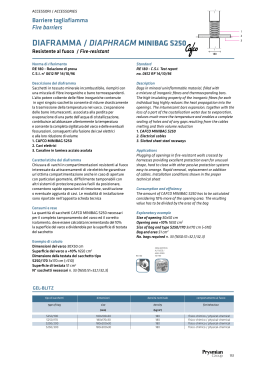
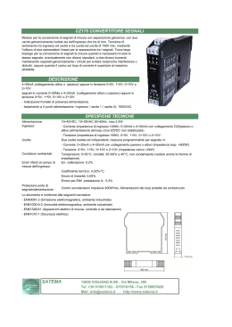
INSTRUCTIONS POUR L’ INSTALLATION
INSTALLATION
Das Gerät benötigt keine speziellen elektrischen oder mechanischen Installationsvorbereitungen. Er kann auf die Normschiene 35mm, Deckeltyp TH35-15 (gem. EN60715) geschraubt
werden. Die Einbaulage hat keinen Einfluss auf die Funktion.
Bevor das Gerät eingebaut wird, muss das Typenschild mit den tatsächlichen Netzgegebenheiten (Spannung, Strom, Eingangsfrequenz und Hilfsspannung) verglichen werden.
• CONFIGURATION D’ENTREE
• EINGANGSKONFIGURATION
L’appareil peut être utilisé pour connexion sue ligne monophasée ou triphasée (3 ou 4 fils).
Choisir le type de connexion désirée et, lors du câblage, respecter scrupuleusement le
schéma de saisie ; une connexion erronée est source inévitable de fausses mesures ou de
dommages à l’appareil. La configuration d’entrée doit être complétée avec la programmation par clavier du type de connexion désiré et des éventuels rapports des transformateurs
de courant et des tensions extérieurs. Connexions possibles :
Das Gerät kann für Einphasen- oder Drehstromleitungsanschluss (3 oder 4 Leitungen) benutzt werden. Wählen Sie die gewünschte Anschlussart und erinnern Sie sich an dass, der
Anschluss gem. Anschlussbilder erfolgt. Falschanschluss führt zu erheblichen Anzeigefehlern! Es können sogar Beschädigungen auftreten.
Die Eingangskonfiguration muss mit den Tastaturprogrammierung der ausgewählten Anschlusstyp und der eventuellen externe Strom- und Spannungswandlerverhältnisse.
Durchführbare Anschlüsse:
1n1E
3n3E
3-2E 1-2
schéma S250/97
schéma S250/99
schéma S250/96
3-2E 1-3
schéma S250/98
3-2E 2-3
schéma S250/94
3n1E
3-1E
3-1E rEA
schéma S250/95
schéma S250/93
schéma S250/100
ligne monophasée
ligne triphasée 4 fils, charge déséquilibré
ligne triphasée 3 fils, charge déséquilibré, transforma
teurs de courant connectés sur les phases L1 e L2
ligne triphasée 3 fils, charge déséquilibré, transforma
teurs de courant connectés sur les phases L1 e L3
ligne triphasée 3 fils, charge déséquilibré, transforma
teurs de courant connectés sur les phases L2 e L3
ligne triphasée 4 fils, charge équilibré
ligne triphasée 3 fils, charge équilibré
ligne triphasée 3 fils, charge équilibré
1
(seulement puissance réactive)
1n1E
3n3E
3-2E 1-2
Schaltbild S250/97
Schaltbild S250/99
Schaltbild S250/96
3-2E 1-3
Schaltbild S250/98
3-2E 2-3
Schaltbild S250/94
3n1E
3-1E
3-1E rEA
Schaltbild S250/95
Schaltbild S250/93
Schaltbild S250/100
Einphasenleitung
4-Leitungen Drehstromleitung, unabgeglichen Last
3-Leitungen Drehstromleitung, unbeliebig belastet,
Stromwandler auf L1 und L2 Phasen geschaltet
3-Leitungen Drehstromleitung, unbeliebig belastet,
Stromwandler auf L1 und L3 Phasen geschaltet
3-Leitungen Drehstromleitung, unbeliebig belastet,
Stromwandler auf L2 und L3 Phasen geschaltet
4-Leitungen Drehstromleitung, beliebig belastet
3-Leitungen Drehstromleitung, beliebig belastet
3-Leitungen Drehstromleitung, beliebig belastet
• CONFIGURATION DE LA SORTIE
L’appareil est prévu pour sortie en courant (mA) ou bien tension (V)
Si on utilise la sortie en courant (mA), il faut se connecter aux bornes 12 (+) et 13 (-), en
laissant libres les bornes 14 – 15 – 17. Si on utilise la sortie en tension (V), il faut se connecter aux bornes 12 (+) et 15 (-) et faire une connexion entre les bornes 14 et 17 (opération à effectuer avec l’appareil non alimenté, en utilisant un câble blindé).
• AUSGANGSKONFIGURATION
Das Gerät ist für Strom- (mA) oder Spannungsausgang (V) vorbereitet.
Wenn Sie Stromausgang (mA) benutzen, sollen Sie zur Klemmen 12 (+) und 13 (-) anschließen und die Klemmen 14 – 15 – 17 freilassen. Wenn Sie Spannungsausgang (V) benutzen, sollen Sie zur Klemmen 12 (+) und 15 (-) anschließen und einen Anschluss
zwischen die Klemmen 14 und 17 ausführen (dieser Anschluss muss mit ungespeisten Gerät und mit isolierten Kabel ausgeführt wird).
• ALIMENTATION AUXILIAIRE
Il est nécessaire pour le correct fonctionnement du transducteur.
Vérifier que la valeur de tension d’alimentation correspond à celle indiquée sur la plaque.
• PROGRAMMATION
ACHTUNG! Bitte kontrollieren, dass den ausgeführten Anschluss und die Tastaturprogrammierung der Ausgangswert übereinstimmen.
Die Ausgangskonfiguration soll mit der Tastaturprogrammierung von Ausgangssignal-nennwert, zusammengefügte Größe, Anfang- und Vollausschlagswert vervollständigt wird.
Pour la programmation sont utilisés les 3 touches sur la face avant :
ENTER pour confirmer les données
DOWN pour déplacer le curseur
UP pour augmenter la valeur chargée
DOWN + ENTER pour entrer dans la programmation
UP + DOWN pour retourner à la page précédente
En phase de programmation, DOWN + ENTER pour sortir de la programmation (sans sauvegarder les modifications)
Für die Programmierung werden die 3 Tasten auf dem Frontrahmen benutzt:
ENTER Datenbestätigung
DOWN Cursorverschiebung
UP Erhöhung des geladenen Wertes
DOWN + ENTER Programmierungseingang
UP + DOWN Rückkehr nach vorherigen Seite
Während der Programmierung, DOWN + ENTER Programmierungsausgang (ohne Änderungsspeicherung).
• PARAMETRES PROGRAMMABLES
•PROGRAMMIERBARE PARAMETER
MITTLERRE LEISTUNG
Integrationszeit: 5, 8, 10, 15, 20, 30, 60 Minute
Wirk- Blind- oder Scheinleistung
Nullstellung des gespeicherten Höchstwertes
fond échelle 20mA
27,712MW
13,856MW
41,568MW
13,856MW
30,4832MW
27,712MW
domain nominal
min. ∆ 0...fond échelle
max. ∆ début...fond échelle
min. ∆ début...fond échelle
Skala Pn
0...100%
0...50%
0...150%
25...50%
85...110%
50...100%
Skalaanfang 4mA
0MW
0MW
0MW
6,928MW
23,5552MW
13,856MW
Vollausschlang 20mA
27,712MW
13,856MW
41,568MW
13,856MW
30,4832MW
27,712MW
Nennbereich
min. ∆ 0...Vollausschlag
max. ∆ Skalaanfang...Vollausschlag
min. ∆ Skalaanfang...Vollausschlag
-mA
2
1
8 11
3
4
7
6
9
INPUT
-mA
+ –
20 21
8
5
2
5
5
1
8 11
3
4
7
6
9
-mA
+ –
14 17 15 12 13
20 21
+
ISTRUMENTI MISURE ELETTRICHE SpA
8
a
A
L1
S1
L
P1
X
S 250/96
Via Travaglia 7
20094 CORSICO (MI)
ITALIA
Tel. +39 02 44 878.1
www.imeitaly.com
[email protected]
X
P1
X
S1
L3
P1
S 250/98
-mA
+ –
2
8
2
5
5
1
8 11
3
4
6
8
7
9
14 17 15 12 13
20 21
+
2
8
5
2
5
5
1
8 11
SUPPLY
OUTPUT
-mA
+ –
14 17 15 12 13
20 21
+
-V
2
a
3
4
7
6
9
8
a
S1
A
L1
S1
A
L1
P1
X
S1
L2
X
S 250/93
P1
X
L2
X
P1
L3
X
P1
INPUT
8
2
5
5
1
8 11
3
4
6
7
9
-mA
+ –
14 17 15 12 13
20 21
+
5
8
X
L2
4
6
7
9
+ –
20 21
+
8
P1
X
X
X
L3
GLOSSARIO
INPUT
2
5
5
1
8 11
3
4
6
7
9
+
-mA
+ –
14 17 15 12 13
20 21
-V
INPUT
SUPPLY
OUTPUT
-mA
+ –
14 17 15 12 13
20 21
+
-V
2
8 11
2
a
5
5
1
8 11
3
4
7
6
9
8 11
a
S1
A
L1
P1
X
L2
X
L2
X
L3
L3
XXX
N
S1
P1
SUPPLY
OUTPUT
X
S1
P1
X
X
S1
P1
XXX
GLOSSARY
GLOSSAIRE
WÖRTERVERZEICHNIS
P
Potenza attiva
Active power
Puissance active
Wirkleistung
P1
Potenza attiva L1
Active power L1
Puissance active L1
Wirkleistung L1
P2
P3
Potenza attiva L2
Active power L2
Puissance active L2
Wirkleistung L2
Potenza attiva L3
Active power L3
Puissance active L3
Wirkleistung L3
Q
Potenza reattiva
Reactive power
Puissance réactive
Blindleistung
Q1
Potenza reattiva L1
Reactive power L1
Puissance réactive L1
Blindleistung L1
Q2
Potenza reattiva L2
Reactive power L2
Puissance réactive L2
Blindleistung L2
Q3
Potenza reattiva L3
Reactive power L3
Puissance réactive L3
Blindleistung L3
S
Potenza apparente
Apparent power
Puissance apparente
Scheinleistung
S1
Potenza apparente L1
Apparent power L1
Puissance apparente L1
Scheinleistung L1
S2
Potenza apparente L2
Apparent power L2
Puissance apparente L2
Scheinleistung L2
S3
PF
Potenza apparente L3
Apparent power L3
Puissance apparente L3
Scheinleistung L3
Fattore di potenza
Power factor
Facteur de puissance
Leistungsfaktor
PF1
Fattore di potenza L1
Power factor L1
Facteur de puissance L1
Leistungsfaktor L1
PF2
Fattore di potenza L2
Power factor L2
Facteur de puissance L2
Leistungsfaktor L2
PF3
Fattore di potenza L3
Power factor L3
Facteur de puissance L3
Leistungsfaktor L3
PD
Potenza media
Average power
Puissance moyenne
Mittlere Leistung
^PD
Valore massimo potenza media
Average power highest value
Valeur maximale de la puissance moyenne
Höchstwert der mittleren Leistung
F
Frequenza
Frequency
Fréquence
Frequenz
D
Angolo di fase
Phase angle
Angle de phase
Phasenwinkel
Linea monofase
Single phase line
Ligne monophasée
Einphaseleitung
S 250/99
S 250/95
N
3
L2
X
X
A
L1
1
8 11
L1
P1
2
5
S1
S1
A
L1
-mA
14 17 15 12 13
-V
2
SUPPLY
OUTPUT
SUPPLY
OUTPUT
-V
2
5
X
S1
L3
S 250/100
INPUT
• CONFIGURAZIONE INGRESSO
• INPUT CONFIGURATION
Lo strumento può essere utilizzato per inserzione su linea monofase o trifase (3 o 4 fili).
Scegliere il tipo di inserzione desiderata e rispettare scrupolosamente nei cablaggi lo
schema di inserzione. Una inesattezza nei collegamenti è inevitabilmente causa di misure
falsate o di danni allo strumento.
La configurazione dell’ingresso, deve essere completata con la programmazione da tastiera del tipo di inserzione selezionato e degli eventuali rapporti TA e TV esterni.
Inserzioni realizzabili:
The meter can be connected with single-phase or 3-phase lines (3 or 4 wires).
Choose the desired connection and, in the wiring, scrupulously respect the wiring diagram;
an error in connection unavoidably leads to wrong measurements or damages to the
meter.
The input configuration must be completed with the keyboard programming of the chosen connection type as well as of any external current and voltage transformer ratios.
Possible connections:
S250/97
S250/99
schema S250/96
schema
schema
3-2E 1-3
schema
S250/98
3-2E 2-3
schema
S250/94
3n1E
3-1E
3-1E rEA
schema
S250/95
schema S250/93
schema S250/100
linea monofase
linea trifase 4 fili, carico squilibrato
linea trifase 3 fili, carico squilibrato,
TA inseriti su fasi L1 e L2
linea trifase 3 fili, carico squilibrato,
TA inseriti su fasi L1 e L3
linea trifase 3 fili, carico squilibrato,
TA inseriti su fasi L2 e L3
linea trifase 4 fili, carico equilibrato
linea trifase 3 fili, carico equilibrato
linea trifase 3 fili, carico equilibrato (solo potenza reattiva)
1n1E
3n3E
3-2E 1-2
wiring diagram
wiring diagram
S250/97
S250/99
S250/96
3-2E 1-3
wiring diagram
S250/98
3-2E 2-3
wiring diagram
S250/94
3n1E
3n1E
3-1E rEA
wiring diagram
S250/95
S250/93
S250/100
wiring diagram
wiring diagram
wiring diagram
single-phase line
4-wire 3-phase line, unbalanced load
3-wire 3-phase line, unbalanced load, current
transformers connected on L1 and L2 phases
3-wire 3-phase line, unbalanced load, current
transformers connected on L1 and L3 phases
3-wire 3-phase line, unbalanced load, current
transformers connected on L2 and L3 phases
4-wire 3-phase line, balanced load
3-wire 3-phase line, balanced load
3-wire 3-phase line, balanced load (just reactive power)
ATTENZIONE! accertarsi della esatta corrispondenza tra lo schema di inserzione
utilizzato e la programmazione del tipo inserzione effettuata da tastiera.
WARNING! Pay attention that the used wiring diagram meets the keyboard programming connection type.
• CONFIGURAZIONE USCITA
• OUTPUT CONFIGURATION
Lo strumento è predisposto per uscita in corrente (mA) oppure tensione (V)
Se si utilizza l’uscita in corrente (mA) connettersi ai terminali 12(+) e 13(-) lasciando liberi
i terminali 14 – 15 – 17.
Se si utilizza l’uscita in tensione (V) connettersi ai terminali 12(+) e 15(-) ed effettuare un
collegamento tra i terminali 14 e 17 (operazione da eseguire con apparecchio non
alimentato, utilizzando cavo isolato).
The meter is set up for current (mA) or voltage (V) output.
If you use the current output (mA) connect with 12(+) and 13(-) terminals, leaving free
terminals 14 – 15 – 17.
If you use the voltage output (V), connect with 12(+) and 13(-) terminals and make a connection between terminals 14 and 17 (this operation must be carried out with nonfed meter, using a shielded cable).
ATTENZIONE! accertarsi della esatta corrispondenza tra il collegamento realizzato
e la programmazione del valore d’uscita effettuata da tastiera.
La configurazione dell’uscita, deve essere completata con la programmazione da tastiera
di: valore nominale segnale d’uscita, grandezza abbinata, valori di inizio e fondo scala.
WARNING! Pay attention that the connection you made meets the keyboard programming output value.
The output configuration must be completed with the keyboard programming of: outgoing signal nominal value, coupled quantity, beginning and full-scale values.
• ALIMENTAZIONE AUSILIARIA
• AUXILIARY SUPPLY
Necessaria per il corretto funzionamento del trasduttore. Verificare che il valore della tensione di alimentazione corrisponda a quello indicato in targa.
It is necessary for a correct working of the transducer. Verify that supply voltage corresponds to the one shown on the label.
• PROGRAMMAZIONE
• PROGRAMMING
L’accesso alla programmazione è protetto da un codice di accesso.Alla richiesta di ingresso
in programmazione, lo strumento chiede all’operatore di inserire, tramite tastiera, la combinazione di accesso (4 cifre), consentendo o negando la possibilità di modifica dei parametri in funzione del codice impostato.
La programmazione è suddivisa su differenti livelli, con differenti chiavi di accesso (password):
password 1000 = tipo inserzione, potenza media, uscita analogica
password 2001 = rapporto trasformazione TA e TV esterni
password 5000 = taratura fine inizio scala (in campo)
password 6000 = taratura fine fondo scala (in campo)
password 7000 = ripristino valori iniziali (programmazione di fabbrica)
Access to programming is protected by an access code.
When one wants to enter the programming, the meter prompts the operator to type the
access combination (4 digits), allowing or denying, according to the received code, the possibility to modify the parameters.
Programming is subdivided on different levels, with different access keys (password):
password 1000 = connection type, average power, analog output
password 2001 = external C.T.’s and V.T.’s ratio of transformation
password 5000 = beginning of scale accurate calibration (in field)
password 6000 = full scale accurate calibration (in field)
password 7000 = initial value reset (factory programming)
10/ 11
INPUT
SUPPLY
OUTPUT
-V
5
X
S1
L2
N
MOUNTING INSTRUCTIONS
The meter does not need any special mechanical or electrical mounting contrivance.
35mm. rail DIN flush mounting, TH35-15 hat-type, according to EN60715
Working is not affected, in any way, by the mounting position.
Before mounting it is necessary to verify that data on the label (voltage, current, input frequency and extra supply voltage) correspond to the real network ones.
1n1E
3n3E
3-2E 1-2
SUPPLY
OUTPUT
-V
2
2
11
ISTRUZIONI PER L’INSTALLAZIONE
Lo strumento non necessita di particolari accorgimenti di installazione meccanici o elettrici.
Montaggio a incastro su profilato 35mm, tipo a cappello TH35-15, secondo EN60715
La posizione di fissaggio risulta completamente indifferente ai fini del funzionamento.
Prima di procedere alla installazione, verificare che i dati di targa (tensione, corrente, frequenza di ingresso e alimentazione ausiliaria) corrispondano a quelli effettivi di rete.
2 3 4
+
14 17 15 12 13
-V
5
L3
ANALOGAUSGANG
Nennwert: ± 20mA, ± 10mA, ± 5mA, 0...5mA, 0...10mA, 0...20mA, 4...20mA, ± 10V, 0...10V,
1...5V
zusammengefügte Größe: siehe Tabelle
Skalaanfangswert
Vollausschlagswert
Leistung entsprechend dem Vollausschlag 50…150%Pn
Mindestes ∆ Skalaanfang – Vollausschlag 25%Pn
Wo: Pn (Nennleistung) = Un x In x √3 x k (eventuelles externes Strom- Spannungswandlerverhältnis)
Un (Nennspannung) = 400V (direkter Anschluss) – 100V (Verbindung durch externen Spannungswandler) In (Nennstrom) = 5A oder 1A
z.B.: Eingang aus Spannungswandler 20’000/100V und Stromwandler 800/5A Ausgang 4...20mA
k = 200 (20’000/100V) x 160 (800/5A) = 32’000
Pn = Un x In x √3 x k = 100V x 5A x √3 x 32'000 = 27'712'000 = 27,712MW
Mindestes ∆ Skalaanfang – Vollausschlag 25%Pn
+
SUPPLY
OUTPUT
a
PUISSANCE MOYENNE
Temps d’intégration: 5, 8, 10, 15, 20, 30, 60 minutes
Puissance : active, réactive, apparente
Mise à zéro de la valeur maximale mémorisée
-V
14 17 15 12 13
S 250/94
INPUT
2
ANSCHLUSSTYP – NETZART
Wahl des Anschlusstyps.
Einphase- oder Drehstromleitung (3 oder 4 Leiter), beliebig oder unbeliebig belastet
début échelle 4mA
0MW
0MW
0MW
6,928MW
23,5552MW
13,856MW
S 250/97
2
CONNEXION
Sélection du type de connexion.
Ligne monophasée ou triphasée (3 ou 4 fils), charge équilibré ou déséquilibré
-mA
Cod. TM8P
Es ist notwendig für den korrekten Betrieb des Messumformers. Bitte kontrollieren, dass
die Versorgungsspannung stimmt mit der Spannung auf dem Schild überein.
Die Änderung von Parameter in der Konfiguration ist nur nach richtiger Eingabe des Zugangscodes (4-stellige Zahl) möglich. Damit in die Programmierung eingetreten werden
kann, verlangt das Gerät die Eingabe der Zutrittskombination. Je nach Eingabe erlaubt
oder sperrt des Gerät jegliche Parameteränderung. Die Programmierung ist auf verschiedenen Stufen, mit verschiedenen Zugriffsschlüssel (Kennwort) geteilt:
Kennwort 1000 = Anschlusstyp, mittlere Leistung, Analogausgang
Kennwort 2001 = externe Strom- und Spannungswandlerverhältnisse
Kennwort 5000 = feine Skalaanfangseichung (ins Feld)
Kennwort 6000 = feine Vollausschlagseichung (ins Feld)
Kennwort 7000 = Rücksetzen auf Anfangswerte (Werkprogrammierung)
+
I
• HILFSSPANNUNG
• PROGRAMMIERUNG
Pn échelle
0...100%
0...50%
0...150%
25...50%
85...110%
50...100%
-V
OUTPUT
14 17 15 12 13
INPUT
L’accès à la programmation est protégé par un code d’accès. Lors de la demande d’accès à
la programmation, l’appareil demande à l’opérateur de saisir au clavier la combinaison
d’accès (4 chiffres), en permettant ou en interdisant la possibilité de modification des paramètres, selon le code chargé. La programmation est subdivisée sur différents niveaux, avec
différents clés d’accès (mots de passe) :
mot de passe 1000 = type de connexion, puissance moyenne, sortie analogique
mot de passe 2001 = rapport de transformation des transformateurs de courant et
de tension externes
mot de passe 5000 = étalonnage fin du début échelle (en le champ)
mot de passe 6000 = étalonnage fin du fond échelle (en le champ)
mot de passe 7000 = restauration des valeurs initiales (programmation de fabrique)
SORTIE ANALOGIQUE
Valeur nominale: ± 20mA, ± 10mA, ± 5mA, 0...5mA, 0...10mA, 0...20mA, 4...20mA, ± 10V,
0...10V, 1...5V
Grandeur associée: voir table
Valeur début échelle
Valeur fond échelle
Puissance correspondant au fond échelle 50…150%Pn
Minimum ∆ début – fond échelle 25%Pn
Où : Pn (puissance nominale) = Un x In x √3 x k (éventuel rapport de transformation transformateurs de courant – transformateurs de tension externes)
Un (tension nominale) = 400V (connexion directe) – 100V (connexion par transformateur
de tension externe) In (courant nominale) = 5A ou 1A
Ex.: entrée de transformateur de tension 20’000/100V et transformateur de courant 800/5A sortie 4…20mA
k = 200 (20’000/100V) x 160 (800/5A) = 32’000
Pn = Un x In x √3 x k = 100V x 5A x √3 x 32'000 = 27'712'000 = 27,712MW
Minimum ∆ début – fond échelle 25%Pn
OUTPUT
2
ACHTUNG! Bitte kontrollieren, dass das benutzte Schaltbild mit der Tastaturprogrammierung der Anschlussart übereinstimmt.
mA
V
(nur Blindleistung)
ATTENTION! Vérifier que le schéma de raccordement utilisé correspond à la programmation du type de raccordement effectuée par le clavier.
ATTENTION! Vérifier que la connexion réalisée correspond à la programmation de
la valeur de sortie effectuée par le clavier.
La configuration de la sortie doit être complétée avec la programmation par clavier de: valeur nominale du signal de sortie, grandeur associée, valeurs de début et fin d’échelle.
10781333
SCHEMI D’INSERZIONE • WIRING DIAGRAMS • SCHEMAS DE RACCORDEMENT • ANSCHLUßBILD
L’appareil ne nécessite pas de soins particuliers pour son installation mécanique et électrique.
Montage encastré sur un rail de 35mm, type à chapeau TH35-15, selon EN60715.
La position de fixation n’a aucune incidence sur le fonctionnement. Avant de procéder à l’installation, il faut vérifier que les données indiquées sur la plaque (tension, courant, fréquence
d’entrée et alimentation auxiliaire) correspondent à celles du secteur.
1n1E
S 250/97
3-1E
S 250/93
Linea trifase 3 fili,carico equilibrato
3-phase 3-wire line, balanced load
Ligne triphasée 3 fils, charge éq.
Drehstrom 3 Leiter, bel belastet
3-1E rEA
S 250/100
Linea trifase 3 fili,carico equilibrato,
potenza reattiva
3-phase 3-wire line, balanced load,
reactve power
Ligne triphasée 3 fils, charge éq.,
puissance réactive
Drehstrom 3 Leiter, bel belastet,
Blindleistung
3n-1E
S 250/95
Linea trifase 4 fili,carico equilibrato
3-phase 4-wire line, balanced load
Ligne triphasée 4 fils, charge éq.
Drehstrom 4 Leiter, bel belastet
3n-3E
S 250/99
Linea trifase 4 fili,carico squilibrato
3-phase 4-wire line, unbalanced load
Ligne triphasée 4 fils, charge dèséq.
Drehstrom 4 Leiter, unbel belastet
3-2E 1-2
S 250/96
Linea trifase 3 fili,carico squilibrato
3-phase 3-wire line, unbalanced load
Ligne triphasée 3 fils, charge dèséq.
Drehstrom 3 Leiter, unbel belastet
3-2E 1-3
S 250/98
Linea trifase 3 fili,carico squilibrato
3-phase 3-wire line, unbalanced load
Ligne triphasée 3 fils, charge dèséq.
Drehstrom 3 Leiter, unbel belastet
3-2E 2-3
S 250/94
Linea trifase 3 fili,carico squilibrato
3-phase 3-wire line, unbalanced load
Ligne triphasée 3 fils, charge dèséq.
Drehstrom 3 Leiter, unbel belastet
Inserzione errata, sequenza fasi
non corretta
Wrong connection, wrong phase sequence
Erreur de connexion, séquence de
phases inexacte
Fehlschalten, falsche Phasenfolge
Err123
Per la programmazione vengono utilizzati i 3 tasti posti sul frontale:
ENTER conferma dei dati
DOWN spostamento cursore
UP incremento valore impostato
DOWN + ENTER ingresso programmazione
UP + DOWN ritorno pagina precedente
In fase di programmazione, DOWN + ENTER uscita programmazione (senza salvataggio
modifiche)
For programming are used the 3 keys on the front board:
ENTER to confirm the data
DOWN to shift the cursor
UP to increase the loaded value
DOWN + ENTER to enter programming
UP + DOWN to return to the previous page
In the programming phase, DOWN + ENTER to leave the programming (without saving
the modifications)
• PROGRAMMABLE PARAMETERS
•PARAMETRI PROGRAMMABILI
CONNECTION
Connection type selection.
Single or 3-phase line (3 or 4 wires), balanced or unbalanced load
INSERZIONE
Selezione del tipo di inserzione.
Linea monofase o trifase (3 o 4 fili), carico equilbrato o squilibrato
AVERAGE POWER
Integration time: 5, 8, 10, 15, 20, 30, 60 minutes
Power: active, reactive, apparent
Maximum stored value reset
POTENZA MEDIA
Tempo integrazione: 5, 8, 10, 15, 20, 30, 60 minuti
Potenza : attiva, reattiva, apparente
Azzeramento valore massimo memorizzato
USCITA ANALOGICA
Valore nominale: ± 20mA, ± 10mA, ± 5mA, 0...5mA, 0...10mA, 0...20mA, 4...20mA, ± 10V,
0...10V, 1...5V
Grandezza associata: vedi tabella
Valore inizio scala
Valore fondo scala
Potenza corrispondente al fondo scala 50...150%Pn
Minimo ∆ inizio – fondo scala 25%Pn
dove: Pn (potenza nominale) = Un x In x √3 x k (eventuale rapporto trasformazione TA – TV esterni)
Un (tensione nominale) = 400V (inserzione diretta) – 100V (inserzione su TV esterno)
In (corrente nominale) = 5A oppure 1A
es. ingresso da TV 20’000/100V e TA 800/5A uscita 4...20mA
k = 200 (20’000/100V) x 160 (800/5A) = 32’000
Pn = Un x In x √3 x k = 100V x 5A x √3 x 32'000 = 27'712'000 = 27,712MW
Minimo ∆ inizio – fondo scala 25%Pn
scala Pn
0...100%
0...50%
0...150%
25...50%
85...110%
50...100%
inizio scala 4mA
0MW
0MW
0MW
6,928MW
23,5552MW
13,856MW
fondo scala 20mA
27,712MW
13,856MW
41,568MW
13,856MW
30,4832MW
27,712MW
campo nominale
min. ∆ 0...fondo scala
max. ∆ inizio...fondo scala
min. ∆ inizio...fondo scala
ANALOG OUTPUT
Nominal value: ± 20mA, ± 10mA, ± 5mA, 0…5mA, 0…10mA, 0…20mA, 4…20mA, ± 10V,
0…10V, 1…5V
Coupled quantity: see table
Beginning of scale value
Full-scale value
Power corresponding to full-scale 50…150%Pn
Minimum ∆ beginning – full-scale 25%Pn
Where: Pn (rated power) = Un x In x √3 x k (possible external C.T.’s - V.T.’s ratio of
transformation)
Un (rated voltage) = 400V (direct connection) – 100V (connection through external voltage
transformer) In (rated current) = 5A or 1A
Ex.: input from voltage transformer 20’000/100V and current transformer 800/5A
output 4…20mA
k = 200 (20’000/100V) x 160 (800/5A) = 32’000
Pn = Un x In x √3 x k = 100V x 5A x √3 x 32'000 = 27'712'000 = 27,712MW
Minimum ∆ beginning – full-scale 25%Pn
Pn scale
0...100%
0...50%
0...150%
25...50%
85...110%
50...100%
beginning of scale 4mA
0MW
0MW
0MW
6,928MW
23,5552MW
13,856MW
full scale 20mA
27,712MW
13,856MW
41,568MW
13,856MW
30,4832MW
27,712MW
rated range
min. ∆ 0...full scale
max. ∆ beginning...full scale
min. ∆ beginning...full scale
10781333
es. ingresso diretto 400V e TA 150/5A uscita 4...20mA
k = 150/5A = 30
Pn = Un x In x √3 x k = 400V x 5A x √3 x 30 = 103’920W = 103,92kW
esempi scale realizzabili:
scala Pn
0...100%
0...50%
0...150%
25...50%
85...110%
50...100%
inizio scala 4mA
0kW
0kW
0kW
25,98kW
88,332kW
51,96kW
fondo scala 20mA
103,92kW
51,96kW
155,88kW
51,96kW
114,312kW
103,92kW
Ex.: direct input 400V and current transformer 150/5A output 4…20mA
K = 150/5A = 30
Pn = Un x In x √3 x k = 400V x 5° x √3 x 30 = 103'920W = 103,92kW
Examples of possible scales:
campo nominale
min. ∆ 0...fondo scala
max. ∆ inizio...fondo scala
min. ∆ inizio...fondo scala
Pn scale
0...100%
0...50%
0...150%
25...50%
85...110%
50...100%
beginnig of scale 4mA
0kW
0kW
0kW
25,98kW
88,332kW
51,96kW
full scale 20mA
103,92kW
51,96kW
155,88kW
51,96kW
114,312kW
103,92kW
P
rated range
min. ∆ 0...full scale
max. ∆ beginning...full scale
min. ∆ beginning...full scale
RAPPORTO TRASFORMAZIONE TRASFORMATORI ESTERNI
KTA= rapporto primario/secondario TA (es. TA800/5A KTA=160)
KTV= rapporto primario/secondario TV (es. 20'000/100V KTV=200,0)
EXTERNAL TRANSFORMER RATIO OF TRANSFORMATION
KTA= current transformer primary/secondary ratio (ex.: CT 800/5A KTA=160)
KTV= voltage transformer primary/secondary ratio (ex.: 20'000/100V KTV=200,0)
KTA: selezionabile nel campo 1...9999
KTV: selezionabile nel campo 1...2999,9
Massimo rapporto impostabile KTA x KTV= 220'000 (ingr. 5A) opp. 2'000'000 (ingr. 1A)
ATTENZIONE: per inserzione diretta (es. linea 400V) impostare KTV=001,0
KTA: selectable in the range 1...9999
KTV: selectable in the range 1...2999,9
Highest loadable ratio KTA x KTV= 220'000 (input 5A) or 2'000'000 (input 1A)
WARNING: for direct connection (ex.: line 400V) load KTV=001,0
TARATURA FINE, IN CAMPO
Inizio scala
Fondo scala
Con apparecchio alimentato e con presenza del segnale di ingresso, è possibile effettuare una taratura accurata in campo, dei valori di inizio e fondo scala..
Le regolazioni di inizio e fondo scala, sono separate e indipendenti.
La funzione di taratura in campo è particolarmente utile nell’abbinamento del trasduttore ad altri apparecchi quali indicatori analogici o digitali, registratori, soglie
di allarme, ecc. e permette di ottimizzare la taratura dell’intera catena di misura.
CALIBRATION IN FIELD
Beginning of scale
Full scale
With fed meter and input signal, it is possible to carry out an accurate calibration in
field of beginning and full-scale values. Beginning and full-scale adjustments are
separate and independent. Calibration in field function is particularly useful when
you have to connect the transducer with other devices such as analog or digital indicators, recorders, alarm thresholds, etc... and it allows to optimize the calibration
of the whole measuring chain.
RIPRISTINO VALORI INIZIALI
Funzione che annulla tutte le modifiche programmate dall’utente, ripristinando la
programmazione di fabbrica di tutti i parametri.
INITIAL VALUE RESET
This function cancels all the modifications programmed by the user, restoring all
the factory-programmed parameters.
Q
S
PI
PI
S
QI
SI
PF
1n1E, 3n3E, 3-2E 1-2,
1-3, 3-2E 2-3, 3n1E,
3-1E, 3-1E rEA
{
P2
P3
Q2
S2
PF
AVERAGE POWER
ACt, rEA, APP
PF
{
20-0-20
MA
F
PUISSANCE MOYENNE
MITTLERE LEISTUNG
{
20-0-20mA, 10-0-10mA, 4-20mA,
0-20mA, 0-10mA, 0-5mA, 5-0-5mA,
10-0-10V, 0-10V, 1-5V
{
Vedi Tabella
See table
Voir table
Siehe Tabelle
k, M
USCITA
ANALOGICA
P, n
PI
PF
Q
QI
{
PD
S
PF
3n3E
3-2E
F
SI
PF
{
k, M
{
P, n
Zeit
fond échelle 20mA
103,92kW
51,96kW
155,88kW
51,96kW
114,312kW
103,92kW
Skala Pn
0...100%
0...50%
0...150%
25...50%
85...110%
50...100%
domaine nominal
min. ∆ 0...fond échelle
max. ∆ début...fond échelle
min. ∆ inizio...fond échelle
Skalaanfang 4mA
0kW
0kW
0kW
25,98kW
88,332kW
51,96kW
Puissance active,
réactive, apparente
Wirk- BlindScheinleistung
Azzeramento
Reset
Remise à zéro
Rückstellung
Valore nominale
Nominal value
Valeur nominale
Nennwert
Grandezza associata
Coupled quantity
Grandeur associée
Zusammengefügte Größe
Vollausschlang 20mA
103,92kW
51,96kW
155,88kW
51,96kW
114,312kW
103,92kW
Nennbereich
min. ∆ 0...Vollausschlag
max. ∆ Skalaanfang...Vollausschlag
min. ∆ Skalaanfang...Vollausschlag
RAPPORT DE TRANSFORMATION DES TRANSFORMATEURS EXTERNES
KTA= rapport primaire/secondaire transformateur de courant (ex. TC 800/5A KTA = 160)
KTV= rapport primaire/secondaire transformateur de tension (ex. 20'000/100V KTV = 200,0)
KTA : sélectionnable en la plage 1…9999
KTV : sélectionnable en la plage 1…2999,9
Maximum rapport chargeable KTA x KTV= 220'000 (entrée 5A) ou bien 2'000'000 (entrée 1A)
ATTENTION : pour connexion directe (ex. ligne 400V) charger KTV = 001,0
ÜBERSETZUNGSVERHÄLTNIS DER EXTERNEN WANDLER
KTA = Verhältnis Primär/Sekundär Stromwandler (z.B.: Stromwandler 800/5A KTA=160)
KTV = Verhältnis Primär/Sekundär Spannungswandler (z.B.: TA 20'000/100V KTV=200,0)
KTA: auswählbar im Bereich 1...9999
KTV: auswählbar im Bereich 1...2999,9
Höchstes ladbares Verhältnis KTA x KTV = 220'000 (Eingang 5A) oder 2'000'000 (Eingang 1A)
ETALONNAGE FIN, EN CHAMP
Début échelle
Fond échelle
Avec l’appareil alimenté et en présence du signal d’entrée, il est possible effectuer
un étalonnage fin en champ des valeurs de début et fond échelle. Les réglages de
début et fond échelle sont séparés et indépendants.
La fonction d’étalonnage en champ est particulièrement utile pour la connexion du
transducteur avec des autres appareils tels que indicateurs analogiques et numériques, enregistreurs, seuils d’alarme, etc… et permet d’optimiser l’étalonnage de
toute la chaîne de mesure.
FEINE EICHUNG, INS FELD
Skalaanfang
Vollausschlag
Mit gespeistem Gerät und mit Eingangssignal ist es möglich eine feine Eichung ins
Feld der Skalaanfangs- sowie Vollausschlagswerte zu machen. Die Skalaanfangsowie Vollausschlagregelungen sind getrennte und unabhängig.
Die Funktion „Eichung ins Feld“ ist besonders nützlich für die Verbindung des Messumformers mit anderen Geräten wie Analog- oder Digitalanzeiger, Registriergeräte, Alarmschwellen, usw. und gestattet die Optimierung der Eichung auf der
ganzen Messkette.
RESTAURATION DES VALEURS INITIALES
Cette fonction annule toutes les modifications programmées par l’utilisateur, en restaurant la programmation de fabrique de tous les paramètres.
RÜCKSETZEN AUF ANFANGSWERTE
Diese Funktion löscht alle benutzerprogrammierte Änderungen und setzt die Werkprogrammierung für alle Parameter zurück.
7 8
Active, reactive,
apparent power
ANALOG
OUTPUT
Moltiplicatore
k (kW/kvar/kVA)
Beginning
of scale M (MW/Mvar/MVA)
Début
échelle
Anfangskale
SORTIE
ANALOGIQUE
ANALOGAUSGANG
0.000, 00.00, 000.0
PD
Temps
Anschluss
Potenza attiva,
reattiva, apparente
Punto decimale valore
Inizio
scala
{
{
Time
Branchement
début échelle 4mA
0kW
0kW
0kW
25,98kW
88,332kW
51,96kW
3n3E
0.000, 00.00, 000.0
D
Connection
Pn échelle
0...100%
0...50%
0...150%
25...50%
85...110%
50...100%
z.B.: direkter Eingang 400V und Stromwandler 150/5A Ausgang 4...20mA
k = 150/5A = 30
Pn = Un x In x √3 x k = 400V x 5A x √3 x 30 = 103’920W = 103,92kW
Beispiele der ausführbaren Skalen:
ACHTUNG: für direkten Anschluss (z.B. Leitung 400V) laden KTV = 001,0
TABELLA • TABLE • TABLE • TABELLE
{
S
PF
{
PD
Q
S3
Tempo
POTENZA MEDIA
no, YES
P
Q3
Inserzione
5, 8, 10, 15, 20, 30, 60 min.
5 6
PF
P
PF
{
SI
1n1E
3-1E
Q
+
QI
VISUALIZZAZIONE • DISPLAY • AFFICHAGE • ANZEIGE
P
Ex.: entrée directe 400V et transformateur de courant 150/5A sortie 4...20mA
k = 150/5A = 30
Pn = Un x In x √3 x k = 400V x 5A x √3 x 30 = 103’920W = 103,92kW
Exemples des échelles réalisables:
PROGRAMMAZIONE • PROGRAMMING • PROGRAMMATION • PROGRAMMIERUNG
Fondo
scala
Full
scale
Fond
échelle
P = positivo
N = negativo
Value decimal point
Point décimal valeur
Dezimalpunktwert
Multiplier
k (kW/kvar/kVA)
M (MW/Mvar/MVA)
Multiplicateur
k (kW/kvar/kVA)
M (MW/Mvar/MVA)
Multiplikator
k (kW/kvar/kVA)
M (MW/Mvar/MVA)
P = positive
N = negative
P = positif
N = négatif
P = positiv
N = negativ
Valore
Value
Valeur
Wert
Punto decimale
Decimal point
Point décimal
Dezimalpunkt
Moltiplicatore
k (kW/kvar/kVA)
M (MW/Mvar/MVA)
Multiplier
k (kW/kvar/kVA)
M (MW/Mvar/MVA)
Multiplicateur
k (kW/kvar/kVA)
M (MW/Mvar/MVA)
Multiplikator
k (kW/kvar/kVA)
M (MW/Mvar/MVA)
P = positivo
N = negativo
P = positive
N = negative
P = positif
N = negatif
P = positiv
N = negativ
Potenza attiva trifase
Three phase active power
Potenza attiva L1
L1 active power
Potenza attiva L2
L2 active power
Potenza attiva L3
L3 active power
Potenza reattiva trifase
Three phase reactive power
Potenza reattiva L1
L1 reactive power
Potenza reattiva L2
L2 reactive power
Potenza reattiva L3
L3 reactive power
Potenza apparente trifase
Three phase apparent power
Potenza apparente L1
L1 apparent power
Potenza apparente L2
L2 apparent power
Potenza apparente L3
L3 apparent power
Cosϕ trifase
Three phase cosϕ
Cosϕ L1
L1 cosϕ
Cosϕ L2
L2 cosϕ
Cosϕ L3
L3 cosϕ
Angolo di fase
Phase angle
Potenza media
Power peak max. demand
Frequenza
Frequency
3-2E 1-2 3-2E 1-3 3-2E 2-3
An.0 3-PH
W
An.0 PH1
W
An.0 PH2
W
An.0 PH3
W
An.0 3-PH
var
An.0 PH1
var
An.0 PH3
var
An.0 PH2
W
An.0 3-PH
VA
An.0 PH1
VA
An.0 PH2
VA
An.0 PH3
VA
An.0 COSt
F
An.0 COS1
F
An.0 COS2
F
An.0 COS3
F
An.0
PD
An.0
F
An.0 3-PH
W
An.0 3-PH
var
An.0 3-PH
VA
An.0 COSt
F
An.0
PD
An.0
F
An.0 3-PH
W
An.0 3-PH
var
An.0 3-PH
VA
An.0 COSt
F
An.0
PD
An.0
F
An.0 3-PH
W
An.0 3-PH
var
An.0 3-PH
VA
An.0 COSt
F
An.0
PD
An.0
F
3n1E
3-1E
An.0 3-PH
W
An.0 3-PH
W
An.0 3-PH
var
An.0 3-PH
VA
An.0 COSt
F
An.0 3-PH
var
3-1E rEA
1n1E
An.0 PH1
W
An.0 3-PH
var
An.0 PH1
var
An.0 3-PH
VA
An.0 PH1
VA
An.0 COSt
F
An.0 dEG
An.0 dEG
An.0
PD
An.0
F
An.0
PD
An.0
F
An.0
PD
An.0
F
An.0 COS1
F
An.0 dEG
An.0
PD
An.0
F
Puissance active triphasée
Three phase active power
Puissance active L1
Three phase active power 1
Puissance active L2
Three phase active power 2
Puissance active L3
Three phase active power 3
Puissance réactive triphasée
Three phase reactive power
Puissance réactive L1
Three phase reactive power 1
Puissance réactive L2
Three phase reactive power 2
Puissance réactive L3
Three phase reactive power 3
Puissance apparente triphasée
Three phase apparent power
Puissance apparente L1
Three phase apparent power 1
Puissance apparente L2
Three phase apparent power 2
Puissance apparente L3
Three phase apparent power 3
Cosϕ triphasée
Three phase cosϕ
Cosϕ L1
Three phase cosϕ 1
Cosϕ L2
Three phase cosϕ 2
Cosϕ L3
Three phase cosϕ 3
Angle de phase
Phase angle
Puissance moyenne
Power peak max. demand
Fréquence
Frequency
TARATURA FINE, IN CAMPO • ACCURATE CALIBRATION ON FIELD • ETALONNAGE FIN, EN CHAMP • FEINE EICHUNG, INS
Agendo sulla tastiera è possibile effettuare una
regolazione fine dei valori di taratura di inizio
e fondo scala.
Impostando la password 7000 vengono ripristinati i valori di taratura impostati in fabbrica.
+
......
Acting on the keyboard it is possible to have
an accurate calibration of beginning and full
scale values.
By loading password 7000 the factory-loaded
calibration values are restored,.
Vollausschlag
F
PD
P
Valore
Value
Valeur
Wert
Inizio scala = password 5000
Beginning of scale = password 5000
Fondo scala = password 6000
Full scale = password 6000
Ripristino valori iniziali = password 7000
Initial value recovery = password 7000
+
......
PD
K RAPPORTO TRASFORMAZIONE
PD
F
CT
TC
CT
K RATIO OF TRASFORMATION
K RAPPORT DE TRANSFORMATION
K ÜBERSETZUNGSVERHÄLTNIS
3-1E
rEA
TA
En agissant sur le clavier est possible d’avoir
un réglage fin des values d’étalonnage de début
et fond échelle. En chargeant le mot de passe
7000, les valeurs d’étalonnage chargées à l’usine
sont restaurées.
Début èchelle = mot de passe 5000
TV
VT
TT
VT
Fond èchelle = mot de passe 6000
3n1E
Restauration des valeurs initiales = mot de passe 7000
F
D
Bei der Verwendung der Tastatur, ist es möglich
eine Feinregulierung der Anfangskala- und
Vollausschlageichungswerte zu machen.
Mit Kennwort 7000 werden die werkgeladene
Eichungswerte wiederhergestellt
+
......
Anfangskala = Kennwort 5000
Vollausschlage = Kennwort 6000
Rücksetzen auf Anfangswerte = Kennwort 7000
10781333
INSTRUCTIONS POUR L’ INSTALLATION
INSTALLATION
L’appareil ne nécessite pas de soins particuliers pour son installation mécanique et électrique.
Montage encastré sur un rail de 35mm, type à chapeau TH35-15, selon EN60715.
La position de fixation n’a aucune incidence sur le fonctionnement. Avant de procéder à l’installation, il faut vérifier que les données indiquées sur la plaque (tension, courant, fréquence
d’entrée et alimentation auxiliaire) correspondent à celles du secteur.
Das Gerät benötigt keine speziellen elektrischen oder mechanischen Installationsvorbereitungen. Er kann auf die Normschiene 35mm, Deckeltyp TH35-15 (gem. EN60715) geschraubt
werden. Die Einbaulage hat keinen Einfluss auf die Funktion.
Bevor das Gerät eingebaut wird, muss das Typenschild mit den tatsächlichen Netzgegebenheiten (Spannung, Strom, Eingangsfrequenz und Hilfsspannung) verglichen werden.
• CONFIGURATION D’ENTREE
• EINGANGSKONFIGURATION
L’appareil peut être utilisé pour connexion sue ligne monophasée ou triphasée (3 ou 4 fils).
Choisir le type de connexion désirée et, lors du câblage, respecter scrupuleusement le
schéma de saisie ; une connexion erronée est source inévitable de fausses mesures ou de
dommages à l’appareil. La configuration d’entrée doit être complétée avec la programmation par clavier du type de connexion désiré et des éventuels rapports des transformateurs de courant et des tensions extérieurs. Connexions possibles :
Das Gerät kann für Einphasen- oder Drehstromleitungsanschluss (3 oder 4 Leitungen)
benutzt werden. Wählen Sie die gewünschte Anschlussart und erinnern Sie sich an dass,
der Anschluss gem. Anschlussbilder erfolgt. Falschanschluss führt zu erheblichen
Anzeigefehlern! Es können sogar Beschädigungen auftreten.
Die Eingangskonfiguration muss mit den Tastaturprogrammierung der ausgewählten
Anschlusstyp und der eventuellen externe Strom- und Spannungswandlerverhältnisse.
Durchführbare Anschlüsse:
1n1E
3n3E
3-2E 1-2
schéma S250/97
schéma S250/99
schéma S250/96
3-2E 1-3
schéma S250/98
3-2E 2-3
schéma S250/94
3n1E
3-1E
3-1E rEA
schéma S250/95
schéma S250/93
schéma S250/100
ligne monophasée
ligne triphasée 4 fils, charge déséquilibré
ligne triphasée 3 fils, charge déséquilibré, transforma
teurs de courant connectés sur les phases L1 e L2
ligne triphasée 3 fils, charge déséquilibré, transforma
teurs de courant connectés sur les phases L1 e L3
ligne triphasée 3 fils, charge déséquilibré, transforma
teurs de courant connectés sur les phases L2 e L3
ligne triphasée 4 fils, charge équilibré
ligne triphasée 3 fils, charge équilibré
ligne triphasée 3 fils, charge équilibré
1n1E
3n3E
3-2E 1-2
Schaltbild S250/97
Schaltbild S250/99
Schaltbild S250/96
3-2E 1-3
Schaltbild S250/98
3-2E 2-3
Schaltbild S250/94
3n1E
3-1E
3-1E rEA
Schaltbild S250/95
Schaltbild S250/93
Schaltbild S250/100
1
(seulement puissance réactive)
Einphasenleitung
4-Leitungen Drehstromleitung, unabgeglichen Last
3-Leitungen Drehstromleitung, unbeliebig belastet,
Stromwandler auf L1 und L2 Phasen geschaltet
3-Leitungen Drehstromleitung, unbeliebig belastet,
Stromwandler auf L1 und L3 Phasen geschaltet
3-Leitungen Drehstromleitung, unbeliebig belastet,
Stromwandler auf L2 und L3 Phasen geschaltet
4-Leitungen Drehstromleitung, beliebig belastet
3-Leitungen Drehstromleitung, beliebig belastet
3-Leitungen Drehstromleitung, beliebig belastet
(nur Blindleistung)
ATTENTION! Vérifier que le schéma de raccordement utilisé correspond à la programmation du type de raccordement effectuée par le clavier.
ACHTUNG! Bitte kontrollieren, dass das benutzte Schaltbild mit der Tastaturpro-grammierung der Anschlussart übereinstimmt.
• CONFIGURATION DE LA SORTIE
L’appareil est prévu pour sortie en courant (mA) ou bien tension (V)
Si on utilise la sortie en courant (mA), il faut se connecter aux bornes 12 (+) et 13 (-), en
laissant libres les bornes 14 – 15 – 17. Si on utilise la sortie en tension (V), il faut se connecter aux bornes 12 (+) et 15 (-) et faire une connexion entre les bornes 14 et 17 (opération à effectuer avec l’appareil non alimenté, en utilisant un câble blindé).
• AUSGANGSKONFIGURATION
Das Gerät ist für Strom- (mA) oder Spannungsausgang (V) vorbereitet.
Wenn Sie Stromausgang (mA) benutzen, sollen Sie zur Klemmen 12 (+) und 13 (-) anschließen und die Klemmen 14 – 15 – 17 freilassen. Wenn Sie Spannungsausgang (V) benutzen, sollen Sie zur Klemmen 12 (+) und 15 (-) anschließen und einen Anschluss zwischen
die Klemmen 14 und 17 ausführen (dieser Anschluss muss mit ungespeisten Gerät und mit
isolierten Kabel ausgeführt wird).
ATTENTION! Vérifier que la connexion réalisée correspond à la programmation de la
valeur de sortie effectuée par le clavier.
La configuration de la sortie doit être complétée avec la programmation par clavier de:
valeur nominale du signal de sortie, grandeur associée, valeurs de début et fin d’échelle.
• ALIMENTATION AUXILIAIRE
Il est nécessaire pour le correct fonctionnement du transducteur.
Vérifier que la valeur de tension d’alimentation correspond à celle indiquée sur la plaque.
• PROGRAMMATION
ACHTUNG! Bitte kontrollieren, dass den ausgeführten Anschluss und die Tasta-turprogrammierung der Ausgangswert übereinstimmen.
Die Ausgangskonfiguration soll mit der Tastaturprogrammierung von Ausgangssignalnennwert, zusammengefügte Größe, Anfang- und Vollausschlagswert vervollständigt wird.
• HILFSSPANNUNG
Es ist notwendig für den korrekten Betrieb des Messumformers. Bitte kontrollieren, dass
die Versorgungsspannung stimmt mit der Spannung auf dem Schild überein.
• PROGRAMMIERUNG
L’accès à la programmation est protégé par un code d’accès. Lors de la demande d’accès à
la programmation, l’appareil demande à l’opérateur de saisir au clavier la combinaison
d’accès (4 chiffres), en permettant ou en interdisant la possibilité de modification des
paramètres, selon le code chargé. La programmation est subdivisée sur différents niveaux,
avec différents clés d’accès (mots de passe) :
mot de passe 1000 = type de connexion, puissance moyenne, sortie analogique
mot de passe 2001 = rapport de transformation des transformateurs de courant et
de tension externes
mot de passe 5000 = étalonnage fin du début échelle (en le champ)
mot de passe 6000 = étalonnage fin du fond échelle (en le champ)
mot de passe 7000 = restauration des valeurs initiales (programmation de fabrique)
Die Änderung von Parameter in der Konfiguration ist nur nach richtiger Eingabe des
Zugangscodes (4-stellige Zahl) möglich. Damit in die Programmierung eingetreten werden
kann, verlangt das Gerät die Eingabe der Zutrittskombination. Je nach Eingabe erlaubt
oder sperrt des Gerät jegliche Parameteränderung. Die Programmierung ist auf verschiedenen Stufen, mit verschiedenen Zugriffsschlüssel (Kennwort) geteilt:
Kennwort 1000 = Anschlusstyp, mittlere Leistung, Analogausgang
Kennwort 2001 = externe Strom- und Spannungswandlerverhältnisse
Kennwort 5000 = feine Skalaanfangseichung (ins Feld)
Kennwort 6000 = feine Vollausschlagseichung (ins Feld)
Kennwort 7000 = Rücksetzen auf Anfangswerte (Werkprogrammierung)
Pour la programmation sont utilisés les 3 touches sur la face avant :
ENTER pour confirmer les données
DOWN pour déplacer le curseur
UP pour augmenter la valeur chargée
DOWN + ENTER pour entrer dans la programmation
UP + DOWN pour retourner à la page précédente
En phase de programmation, DOWN + ENTER pour sortir de la programmation (sans sauvegarder les modifications)
Für die Programmierung werden die 3 Tasten auf dem Frontrahmen benutzt:
ENTER Datenbestätigung
DOWN Cursorverschiebung
UP Erhöhung des geladenen Wertes
DOWN + ENTER Programmierungseingang
UP + DOWN Rückkehr nach vorherigen Seite
Während der Programmierung, DOWN + ENTER Programmierungsausgang (ohne Änderungsspeicherung).
• PARAMETRES PROGRAMMABLES
•PROGRAMMIERBARE PARAMETER
CONNEXION
Sélection du type de connexion.
Ligne monophasée ou triphasée (3 ou 4 fils), charge équilibré ou déséquilibré
ANSCHLUSSTYP – NETZART
Wahl des Anschlusstyps.
Einphase- oder Drehstromleitung (3 oder 4 Leiter), beliebig oder unbeliebig belastet
PUISSANCE MOYENNE
Temps d’intégration: 5, 8, 10, 15, 20, 30, 60 minutes
Puissance : active, réactive, apparente
Mise à zéro de la valeur maximale mémorisée
MITTLERRE LEISTUNG
Integrationszeit: 5, 8, 10, 15, 20, 30, 60 Minute
Wirk- Blind- oder Scheinleistung
Nullstellung des gespeicherten Höchstwertes
SORTIE ANALOGIQUE
Valeur nominale: ± 20mA, ± 10mA, ± 5mA, 0...5mA, 0...10mA, 0...20mA, 4...20mA, ± 10V,
0...10V, 1...5V
Grandeur associée: voir table
Valeur début échelle
Valeur fond échelle
Puissance correspondant au fond échelle 50…150%Pn
Minimum ∆ début – fond échelle 25%Pn
Où : Pn (puissance nominale) = Un x In x √3 x k (éventuel rapport de transformation transformateurs de courant – transformateurs de tension externes)
Un (tension nominale) = 400V (connexion directe) – 100V (connexion par transformateur
de tension externe) In (courant nominale) = 5A ou 1A
Ex.: entrée de transformateur de tension 20’000/100V et transformateur de courant
800/5A sortie 4…20mA
k = 200 (20’000/100V) x 160 (800/5A) = 32’000
Pn = Un x In x √3 x k = 100V x 5A x √3 x 32'000 = 27'712'000 = 27,712MW
Minimum ∆ début – fond échelle 25%Pn
Exemples des échelles réalisables:
Pn échelle
0...100%
0...50%
0...150%
25...50%
85...110%
50...100%
début échelle 4mA
0MW
0MW
0MW
6,928MW
23,5552MW
13,856MW
fond échelle 20mA
27,712MW
13,856MW
41,568MW
13,856MW
30,4832MW
27,712MW
domain nominal
min. ∆ 0...fond échelle
max. ∆ début...fond échelle
min. ∆ début...fond échelle
ANALOGAUSGANG
Nennwert: ± 20mA, ± 10mA, ± 5mA, 0...5mA, 0...10mA, 0...20mA, 4...20mA, ± 10V, 0...10V,
1...5V
zusammengefügte Größe: siehe Tabelle
Skalaanfangswert
Vollausschlagswert
Leistung entsprechend dem Vollausschlag 50…150%Pn
Mindestes ∆ Skalaanfang – Vollausschlag 25%Pn
Wo: Pn (Nennleistung) = Un x In x √3 x k (eventuelles externes Strom- Spannung-swandlerverhältnis)
Un (Nennspannung) = 400V (direkter Anschluss) – 100V (Verbindung durch externen
Spannungswandler) In (Nennstrom) = 5A oder 1A
z.B.: Eingang aus Spannungswandler 20’000/100V und Stromwandler 800/5A Ausgang
4...20mA
k = 200 (20’000/100V) x 160 (800/5A) = 32’000
Pn = Un x In x √3 x k = 100V x 5A x √3 x 32'000 = 27'712'000 = 27,712MW
Mindestes ∆ Skalaanfang – Vollausschlag 25%Pn
Beispiele der ausführbaren Skalen:
Skala Pn
0...100%
0...50%
0...150%
25...50%
85...110%
50...100%
Skalaanfang 4mA
0MW
0MW
0MW
6,928MW
23,5552MW
13,856MW
Vollausschlang 20mA
27,712MW
13,856MW
41,568MW
13,856MW
30,4832MW
27,712MW
Nennbereich
min. ∆ 0...Vollausschlag
max. ∆ Skalaanfang...Vollausschlag
min. ∆ Skalaanfang...Vollausschlag
10781332
SCHEMI D’INSERZIONE • WIRING DIAGRAMS • SCHEMAS DE RACCORDEMENT • ANSCHLUßBILD
mA
V
OUTPUT
-V
+
OUTPUT
-mA
14 17 15 12 13
+
-mA
2
S 250/97
S 250/94
INPUT
+
2
5
1
8 11
3
4
7
6
9
-mA
+ –
14 17 15 12 13
20 21
2
8
5
2
11
INPUT
SUPPLY
OUTPUT
-V
2
-V
14 17 15 12 13
2
5
5
-mA
+ –
14 17 15 12 13
20 21
+
-V
1
8 11
SUPPLY
OUTPUT
3
4
7
6
9
8
a
A
L1
S1
L
P1
N
S 250/96
X
S1
P1
-mA
+ –
2
8
2
5
5
1
8 11
3
4
7
6
8
9
14 17 15 12 13
20 21
+
2
8
5
2
a
INPUT
SUPPLY
OUTPUT
-V
5
X
P1
L3
S 250/98
INPUT
2
X
S1
L2
X
2
5
5
-mA
+ –
14 17 15 12 13
20 21
+
-V
1
8 11
SUPPLY
OUTPUT
3
4
7
6
9
8
a
S1
A
L1
S1
A
L1
P1
X
S1
L2
X
S 250/93
P1
X
L2
X
P1
L3
X
P1
S 250/100
INPUT
INPUT
-mA
+ –
14 17 15 12 13
20 21
+
2
8
5
2
5
5
1
8 11
3
4
7
6
9
5
8
a
X
L2
3
4
6
7
9
+ –
14 17 15 12 13
20 21
8
L3
P1
X
X
L2
X
X
X
L3
S 250/99
S 250/95
INPUT
2
5
5
1
8 11
3
4
6
7
9
+
INPUT
SUPPLY
OUTPUT
-mA
+ –
14 17 15 12 13
20 21
-V
2
8 11
2
5
5
1
8 11
SUPPLY
OUTPUT
-mA
+ –
14 17 15 12 13
20 21
+
-V
a
3
4
7
6
9
8 11
a
S1
A
L1
P1
X
L2
X
L2
X
L3
N
1
8 11
L1
P1
A
L1
5
-mA
+
-V
S1
S1
A
L1
2
2
SUPPLY
OUTPUT
SUPPLY
OUTPUT
-V
2
X
S1
L3
L3
XXX
N
S1
P1
X
S1
P1
X
X
S1
P1
XXX
10781332
10781333
I
Cod. TM8P
3
ISTRUMENTI MISURE ELETTRICHE SpA
Via Travaglia 7
20094 CORSICO (MI)
ITALIA
Tel. + 39 02 44 878.1
www.imeitaly.com
[email protected]
GLOSSARIO
P
Potenza attiva
P1
Potenza attiva L1
P2
P3
Potenza attiva L2
Potenza attiva L3
Q
Potenza reattiva
Q1
Potenza reattiva L1
Q2
Potenza reattiva L2
Q3
Potenza reattiva L3
S
Potenza apparente
S1
Potenza apparente L1
S2
Potenza apparente L2
S3
PF
Potenza apparente L3
Fattore di potenza
PF1
Fattore di potenza L1
PF2
Fattore di potenza L2
PF3
Fattore di potenza L3
PD
Potenza media
^PD
Valore massimo potenza media
F
Frequenza
D
GLOSSARY
GLOSSAIRE
10/ 11
WÖRTERVERZEICHNIS
Active power
Puissance active
Wirkleistung
Active power L1
Puissance active L1
Wirkleistung L1
Active power L2
Puissance active L2
Wirkleistung L2
Active power L3
Puissance active L3
Wirkleistung L3
Reactive power
Puissance réactive
Blindleistung
Reactive power L1
Puissance réactive L1
Blindleistung L1
Reactive power L2
Puissance réactive L2
Blindleistung L2
Reactive power L3
Puissance réactive L3
Blindleistung L3
Apparent power
Puissance apparente
Scheinleistung
Apparent power L1
Puissance apparente L1
Scheinleistung L1
Apparent power L2
Puissance apparente L2
Scheinleistung L2
Apparent power L3
Puissance apparente L3
Scheinleistung L3
Power factor
Facteur de puissance
Leistungsfaktor
Power factor L1
Facteur de puissance L1
Leistungsfaktor L1
Power factor L2
Facteur de puissance L2
Leistungsfaktor L2
Power factor L3
Facteur de puissance L3
Leistungsfaktor L3
Average power
Puissance moyenne
Mittlere Leistung
Average power highest value
Valeur maximale de la puissance moyenne
Höchstwert der mittleren Leistung
Frequency
Fréquence
Frequenz
Angolo di fase
Phase angle
Angle de phase
Phasenwinkel
Single phase line
Ligne monophasée
Einphaseleitung
1n1E
S 250/97
Linea monofase
3-1E
S 250/93
Linea trifase 3 fili,carico equilibrato
3-phase 3-wire line, balanced load
Ligne triphasée 3 fils, charge éq.
Drehstrom 3 Leiter, bel belastet
3-1E rEA
S 250/100
Linea trifase 3 fili,carico equilibrato, potenza reattiva
3-phase 3-wire line, balanced load,
reactve power
Ligne triphasée 3 fils, charge éq.,
puissance réactive
Drehstrom 3 Leiter, bel belastet,
Blindleistung
3n-1E
S 250/95
Linea trifase 4 fili,carico equilibrato
3-phase 4-wire line, balanced load
Ligne triphasée 4 fils, charge éq.
Drehstrom 4 Leiter, bel belastet
3n-3E
S 250/99
Linea trifase 4 fili,carico squilibrato
3-phase 4-wire line, unbalanced load
Ligne triphasée 4 fils, charge dèséq.
Drehstrom 4 Leiter, unbel belastet
3-2E 1-2
S 250/96
Linea trifase 3 fili,carico squilibrato
3-phase 3-wire line, unbalanced load
Ligne triphasée 3 fils, charge dèséq.
Drehstrom 3 Leiter, unbel belastet
3-2E 1-3
S 250/98
Linea trifase 3 fili,carico squilibrato
3-phase 3-wire line, unbalanced load
Ligne triphasée 3 fils, charge dèséq.
Drehstrom 3 Leiter, unbel belastet
3-2E 2-3
S 250/94
Linea trifase 3 fili,carico squilibrato
3-phase 3-wire line, unbalanced load
Ligne triphasée 3 fils, charge dèséq.
Drehstrom 3 Leiter, unbel belastet
Inserzione errata, sequenza fasi
non corretta
Wrong connection, wrong phase
sequence
Erreur de connexion, séquence de
phases inexacte
Fehlschalten, falsche Phasenfolge
Err123
10781332
ISTRUZIONI PER L’INSTALLAZIONE
MOUNTING INSTRUCTIONS
Lo strumento non necessita di particolari accorgimenti di installazione meccanici o elettrici.
Montaggio a incastro su profilato 35mm, tipo a cappello TH35-15, secondo EN60715
La posizione di fissaggio risulta completamente indifferente ai fini del funzionamento.
Prima di procedere alla installazione, verificare che i dati di targa (tensione, corrente, frequenza di ingresso e alimentazione ausiliaria) corrispondano a quelli effettivi di rete.
The meter does not need any special mechanical or electrical mounting contrivance.
35mm. rail DIN flush mounting, TH35-15 hat-type, according to EN60715
Working is not affected, in any way, by the mounting position.
Before mounting it is necessary to verify that data on the label (voltage, current, input frequency and extra supply voltage) correspond to the real network ones.
• CONFIGURAZIONE INGRESSO
• INPUT CONFIGURATION
Lo strumento può essere utilizzato per inserzione su linea monofase o trifase (3 o 4 fili).
Scegliere il tipo di inserzione desiderata e rispettare scrupolosamente nei cablaggi lo schema di inserzione. Una inesattezza nei collegamenti è inevitabilmente causa di misure falsate o di danni allo strumento.
La configurazione dell’ingresso, deve essere completata con la programmazione da tastiera del tipo di inserzione selezionato e degli eventuali rapporti TA e TV esterni.
Inserzioni realizzabili:
The meter can be connected with single-phase or 3-phase lines (3 or 4 wires).
Choose the desired connection and, in the wiring, scrupulously respect the wiring diagram; an error in connection unavoidably leads to wrong measurements or damages to
the meter.
The input configuration must be completed with the keyboard programming of the chosen connection type as well as of any external current and voltage transformer ratios.
Possible connections:
S250/97
S250/99
schema S250/96
1n1E
3n3E
3-2E 1-2
schema
3-2E 1-3
schema
S250/98
3-2E 2-3
schema
S250/94
3n1E
3-1E
3-1E rEA
schema
S250/95
S250/93
S250/100
linea monofase
linea trifase 4 fili, carico squilibrato
linea trifase 3 fili, carico squilibrato,
TA inseriti su fasi L1 e L2
linea trifase 3 fili, carico squilibrato,
TA inseriti su fasi L1 e L3
linea trifase 3 fili, carico squilibrato,
TA inseriti su fasi L2 e L3
linea trifase 4 fili, carico equilibrato
linea trifase 3 fili, carico equilibrato
linea trifase 3 fili, carico equilibrato (solo potenza reattiva)
schema
schema
schema
1n1E
3n3E
3-2E 1-2
wiring diagram
wiring diagram
S250/97
S250/99
S250/96
3-2E 1-3
wiring diagram
S250/98
wiring diagram
4
3-2E 2-3
wiring diagram
S250/94
3n1E
3n1E
3-1E rEA
wiring diagram
S250/95
S250/93
S250/100
wiring diagram
wiring diagram
single-phase line
4-wire 3-phase line, unbalanced load
3-wire 3-phase line, unbalanced load, current
transformers connected on L1 and L2 phases
3-wire 3-phase line, unbalanced load, current
transformers connected on L1 and L3 phases
3-wire 3-phase line, unbalanced load, current
transformers connected on L2 and L3 phases
4-wire 3-phase line, balanced load
3-wire 3-phase line, balanced load
3-wire 3-phase line, balanced load (just reactive power)
ATTENZIONE! accertarsi della esatta corrispondenza tra lo schema di inserzione utilizzato
e la programmazione del tipo inserzione effettuata da tastiera.
WARNING! Pay attention that the used wiring diagram meets the keyboard programming
connection type.
• CONFIGURAZIONE USCITA
• OUTPUT CONFIGURATION
Lo strumento è predisposto per uscita in corrente (mA) oppure tensione (V)
Se si utilizza l’uscita in corrente (mA) connettersi ai terminali 12(+) e 13(-) lasciando liberi i
terminali 14 – 15 – 17.
Se si utilizza l’uscita in tensione (V) connettersi ai terminali 12(+) e 15(-) ed effettuare un
collegamento tra i terminali 14 e 17 (operazione da eseguire con apparecchio non alimentato, utilizzando cavo isolato).
The meter is set up for current (mA) or voltage (V) output.
If you use the current output (mA) connect with 12(+) and 13(-) terminals, leaving free
terminals 14 – 15 – 17.
If you use the voltage output (V), connect with 12(+) and 13(-) terminals and make a connection between terminals 14 and 17 (this operation must be carried out with non-fed
meter, using a shielded cable).
ATTENZIONE! accertarsi della esatta corrispondenza tra il collegamento realizzato e la
programmazione del valore d’uscita effettuata da tastiera.
La configurazione dell’uscita, deve essere completata con la programmazione da tastiera
di: valore nominale segnale d’uscita, grandezza abbinata, valori di inizio e fondo scala.
WARNING! Pay attention that the connection you made meets the keyboard programming output value.
The output configuration must be completed with the keyboard programming of: outgoing signal nominal value, coupled quantity, beginning and full-scale values.
• ALIMENTAZIONE AUSILIARIA
• AUXILIARY SUPPLY
Necessaria per il corretto funzionamento del trasduttore. Verificare che il valore della tensione di alimentazione corrisponda a quello indicato in targa.
It is necessary for a correct working of the transducer. Verify that supply voltage corresponds to the one shown on the label.
• PROGRAMMAZIONE
• PROGRAMMING
L’accesso alla programmazione è protetto da un codice di accesso.Alla richiesta di ingresso
in programmazione, lo strumento chiede all’operatore di inserire, tramite tastiera, la combinazione di accesso (4 cifre), consentendo o negando la possibilità di modifica dei parametri in funzione del codice impostato.
La programmazione è suddivisa su differenti livelli, con differenti chiavi di accesso (password):
password 1000 = tipo inserzione, potenza media, uscita analogica
password 2001 = rapporto trasformazione TA e TV esterni
password 5000 = taratura fine inizio scala (in campo)
password 6000 = taratura fine fondo scala (in campo)
password 7000 = ripristino valori iniziali (programmazione di fabbrica)
Per la programmazione vengono utilizzati i 3 tasti posti sul frontale:
ENTER conferma dei dati
DOWN spostamento cursore
UP incremento valore impostato
DOWN + ENTER ingresso programmazione
UP + DOWN ritorno pagina precedente
In fase di programmazione, DOWN + ENTER uscita programmazione (senza salvataggio
modifiche)
Access to programming is protected by an access code.
When one wants to enter the programming, the meter prompts the operator to type the
access combination (4 digits), allowing or denying, according to the received code, the
possibility to modify the parameters.
Programming is subdivided on different levels, with different access keys (password):
password 1000 = connection type, average power, analog output
password 2001 = external C.T.’s and V.T.’s ratio of transformation
password 5000 = beginning of scale accurate calibration (in field)
password 6000 = full scale accurate calibration (in field)
password 7000 = initial value reset (factory programming)
For programming are used the 3 keys on the front board:
ENTER to confirm the data
DOWN to shift the cursor
UP to increase the loaded value
DOWN + ENTER to enter programming
UP + DOWN to return to the previous page
In the programming phase, DOWN + ENTER to leave the programming (without saving
the modifications)
• PROGRAMMABLE PARAMETERS
•PARAMETRI PROGRAMMABILI
CONNECTION
Connection type selection.
Single or 3-phase line (3 or 4 wires), balanced or unbalanced load
INSERZIONE
Selezione del tipo di inserzione.
Linea monofase o trifase (3 o 4 fili), carico equilbrato o squilibrato
POTENZA MEDIA
Tempo integrazione: 5, 8, 10, 15, 20, 30, 60 minuti
Potenza : attiva, reattiva, apparente
Azzeramento valore massimo memorizzato
AVERAGE POWER
Integration time: 5, 8, 10, 15, 20, 30, 60 minutes
Power: active, reactive, apparent
Maximum stored value reset
USCITA ANALOGICA
Valore nominale: ± 20mA, ± 10mA, ± 5mA, 0...5mA, 0...10mA, 0...20mA, 4...20mA, ± 10V,
0...10V, 1...5V
Grandezza associata: vedi tabella
Valore inizio scala
Valore fondo scala
Potenza corrispondente al fondo scala 50...150%Pn
Minimo ∆ inizio – fondo scala 25%Pn
dove: Pn (potenza nominale) = Un x In x √3 x k (eventuale rapporto trasformazione TA –
TV esterni)
Un (tensione nominale) = 400V (inserzione diretta) – 100V (inserzione su TV esterno)
In (corrente nominale) = 5A oppure 1A
es. ingresso da TV 20’000/100V e TA 800/5A uscita 4...20mA
k = 200 (20’000/100V) x 160 (800/5A) = 32’000
Pn = Un x In x √3 x k = 100V x 5A x √3 x 32'000 = 27'712'000 = 27,712MW
Minimo ∆ inizio – fondo scala 25%Pn
esempi scale realizzabili:
scala Pn
0...100%
0...50%
0...150%
25...50%
85...110%
50...100%
inizio scala 4mA
0MW
0MW
0MW
6,928MW
23,5552MW
13,856MW
fondo scala 20mA
27,712MW
13,856MW
41,568MW
13,856MW
30,4832MW
27,712MW
campo nominale
min. ∆ 0...fondo scala
max. ∆ inizio...fondo scala
min. ∆ inizio...fondo scala
ANALOG OUTPUT
Nominal value: ± 20mA, ± 10mA, ± 5mA, 0…5mA, 0…10mA, 0…20mA, 4…20mA, ± 10V,
0…10V, 1…5V
Coupled quantity: see table
Beginning of scale value
Full-scale value
Power corresponding to full-scale 50…150%Pn
Minimum ∆ beginning – full-scale 25%Pn
Where: Pn (rated power) = Un x In x √3 x k (possible external C.T.’s - V.T.’s ratio of transformation)
Un (rated voltage) = 400V (direct connection) – 100V (connection through external voltage transformer) In (rated current) = 5A or 1A
Ex.: input from voltage transformer 20’000/100V and current transformer 800/5A output
4…20mA
k = 200 (20’000/100V) x 160 (800/5A) = 32’000
Pn = Un x In x √3 x k = 100V x 5A x √3 x 32'000 = 27'712'000 = 27,712MW
Minimum ∆ beginning – full-scale 25%Pn
Examples of possible scales:
Pn scale
0...100%
0...50%
0...150%
25...50%
85...110%
50...100%
beginning of scale 4mA
0MW
0MW
0MW
6,928MW
23,5552MW
13,856MW
full scale 20mA
27,712MW
13,856MW
41,568MW
13,856MW
30,4832MW
27,712MW
rated range
min. ∆ 0...full scale
max. ∆ beginning...full scale
min. ∆ beginning...full scale
10781332
es. ingresso diretto 400V e TA 150/5A uscita 4...20mA
k = 150/5A = 30
Pn = Un x In x √3 x k = 400V x 5A x √3 x 30 = 103’920W = 103,92kW
esempi scale realizzabili:
scala Pn
0...100%
0...50%
0...150%
25...50%
85...110%
50...100%
inizio scala 4mA
0kW
0kW
0kW
25,98kW
88,332kW
51,96kW
fondo scala 20mA
103,92kW
51,96kW
155,88kW
51,96kW
114,312kW
103,92kW
Ex.: direct input 400V and current transformer 150/5A output 4…20mA
K = 150/5A = 30
Pn = Un x In x √3 x k = 400V x 5° x √3 x 30 = 103'920W = 103,92kW
Examples of possible scales:
campo nominale
min. ∆ 0...fondo scala
max. ∆ inizio...fondo scala
min. ∆ inizio...fondo scala
Pn scale
0...100%
0...50%
0...150%
25...50%
85...110%
50...100%
beginnig of scale 4mA
0kW
0kW
0kW
25,98kW
88,332kW
51,96kW
full scale 20mA
103,92kW
51,96kW
155,88kW
51,96kW
114,312kW
103,92kW
rated range
min. ∆ 0...full scale
max. ∆ beginning...full scale
min. ∆ beginning...full scale
RAPPORTO TRASFORMAZIONE TRASFORMATORI ESTERNI
KTA= rapporto primario/secondario TA (es. TA800/5A KTA=160)
KTV= rapporto primario/secondario TV (es. 20'000/100V KTV=200,0)
EXTERNAL TRANSFORMER RATIO OF TRANSFORMATION
KTA= current transformer primary/secondary ratio (ex.: CT 800/5A KTA=160)
KTV= voltage transformer primary/secondary ratio (ex.: 20'000/100V KTV=200,0)
KTA: selezionabile nel campo 1...9999
KTV: selezionabile nel campo 1...2999,9
Massimo rapporto impostabile KTA x KTV= 220'000 (ingr. 5A) opp. 2'000'000 (ingr. 1A)
ATTENZIONE: per inserzione diretta (es. linea 400V) impostare KTV=001,0
KTA: selectable in the range 1...9999
KTV: selectable in the range 1...2999,9
Highest loadable ratio KTA x KTV= 220'000 (input 5A) or 2'000'000 (input 1A)
WARNING: for direct connection (ex.: line 400V) load KTV=001,0
TARATURA FINE, IN CAMPO
Inizio scala
Fondo scala
Con apparecchio alimentato e con presenza del segnale di ingresso, è possibile
effettuare una taratura accurata in campo, dei valori di inizio e fondo scala..
Le regolazioni di inizio e fondo scala, sono separate e indipendenti.
La funzione di taratura in campo è particolarmente utile nell’abbinamento del trasduttore ad altri apparecchi quali indicatori analogici o digitali, registratori, soglie
di allarme, ecc. e permette di ottimizzare la taratura dell’intera catena di misura.
CALIBRATION IN FIELD
Beginning of scale
Full scale
With fed meter and input signal, it is possible to carry out an accurate calibration
in field of beginning and full-scale values. Beginning and full-scale adjustments
are separate and independent. Calibration in field function is particularly useful
when you have to connect the transducer with other devices such as analog or
digital indicators, recorders, alarm thresholds, etc... and it allows to optimize the
calibration of the whole measuring chain.
RIPRISTINO VALORI INIZIALI
Funzione che annulla tutte le modifiche programmate dall’utente, ripristinando la
programmazione di fabbrica di tutti i parametri.
INITIAL VALUE RESET
This function cancels all the modifications programmed by the user, restoring all
the factory-programmed parameters.
5
VISUALIZZAZIONE • DISPLAY • AFFICHAGE • ANZEIGE
P
PI
Q
QI
S
SI
PF
PF
PD
3n3E
F
P2
P3
P
Q2
Q3
Q
S2
S3
S
PF
PF
PF
PD
3-2E
F
P
PD
PD
3-1E
rEA
F
10781332
PROGRAM
P
PI
Q
QI
{
S
SI
{
PF
PF
{
PD
+
1n1E, 3n3E, 3-2E 1-2,
1-3, 3-2E 2-3, 3n1E,
3-1E, 3-1E rEA
5, 8, 10, 15, 20, 30, 60 min.
ACt, rEA, APP
6
{
20-0-20
MA
F
1n1E
3-1E
D
no, YES
{
20-0-20mA, 10-0-10mA, 4-20mA,
0-20mA, 0-10mA, 0-5mA, 5-0-5mA,
10-0-10V, 0-10V, 1-5V
{
Vedi Tabella
See table
Voir table
Siehe Tabelle
{
0.000, 00.00, 000.0
{
k, M
{
P
Q
S
PF
PD
P, n
PI
QI
{
0.000, 00.00, 000.0
SI
{
PF
{
k, M
P, n
F
3n1E
D
10781332
MMAZIONE • PROGRAMMING • PROGRAMMATION • PROGRAMMIERUNG
POTENZA MEDIA
AVERAGE POWER
PUISSANCE MOYENNE
MITTLERE LEISTUNG
ANALOG
OUTPUT
Connection
Branchement
Anschluss
Tempo
Time
Temps
Zeit
Potenza attiva,
reattiva, apparente
Active, reactive,
apparent power
Puissance active,
réactive, apparente
Wirk- BlindScheinleistung
7
Azzeramento
Reset
Remise à zéro
Rückstellung
Valore nominale
Nominal value
Valeur nominale
Nennwert
Grandezza associata
Coupled quantity
Grandeur associée
Zusammengefügte Größe
Punto decimale valore
Value decimal point
Point décimal valeur
Dezimalpunktwert
Multiplier
k (kW/kvar/kVA)
M (MW/Mvar/MVA)
Multiplicateur
k (kW/kvar/kVA)
M (MW/Mvar/MVA)
Multiplikator
k (kW/kvar/kVA)
M (MW/Mvar/MVA)
P = positivo
N = negativo
P = positive
N = negative
P = positif
N = négatif
P = positiv
N = negativ
Valore
Value
Valeur
Wert
Punto decimale
Decimal point
Point décimal
Dezimalpunkt
Moltiplicatore
k (kW/kvar/kVA)
M (MW/Mvar/MVA)
Multiplier
k (kW/kvar/kVA)
M (MW/Mvar/MVA)
Multiplicateur
k (kW/kvar/kVA)
M (MW/Mvar/MVA)
Multiplikator
k (kW/kvar/kVA)
M (MW/Mvar/MVA)
P = positivo
N = negativo
P = positive
N = negative
P = positif
N = negatif
P = positiv
N = negativ
Valore
Value
Valeur
Wert
TA
CT
TC
CT
TV
VT
TT
VT
Inizio
scala
USCITA
ANALOGICA
Inserzione
Moltiplicatore
k (kW/kvar/kVA)
Beginning
of scale M (MW/Mvar/MVA)
Début
échelle
Anfangskale
SORTIE
ANALOGIQUE
ANALOGAUSGANG
Fondo
scala
Full
scale
Fond
échelle
Vollausschlag
K RAPPORTO TRASFORMAZIONE
K RATIO OF TRASFORMATION
K RAPPORT DE TRANSFORMATION
K ÜBERSETZUNGSVERHÄLTNIS
10781332
Ex.: entrée directe 400V et transformateur de courant 150/5A sortie 4...20mA
k = 150/5A = 30
Pn = Un x In x √3 x k = 400V x 5A x √3 x 30 = 103’920W = 103,92kW
Exemples des échelles réalisables:
Pn échelle
0...100%
0...50%
0...150%
25...50%
85...110%
50...100%
début échelle 4mA
0kW
0kW
0kW
25,98kW
88,332kW
51,96kW
fond échelle 20mA
103,92kW
51,96kW
155,88kW
51,96kW
114,312kW
103,92kW
z.B.: direkter Eingang 400V und Stromwandler 150/5A Ausgang 4...20mA
k = 150/5A = 30
Pn = Un x In x √3 x k = 400V x 5A x √3 x 30 = 103’920W = 103,92kW
Beispiele der ausführbaren Skalen:
Skala Pn
0...100%
0...50%
0...150%
25...50%
85...110%
50...100%
domaine nominal
min. ∆ 0...fond échelle
max. ∆ début...fond échelle
min. ∆ inizio...fond échelle
Skalaanfang 4mA
0kW
0kW
0kW
25,98kW
88,332kW
51,96kW
Vollausschlang 20mA
103,92kW
51,96kW
155,88kW
51,96kW
114,312kW
103,92kW
Nennbereich
min. ∆ 0...Vollausschlag
max. ∆ Skalaanfang...Vollausschlag
min. ∆ Skalaanfang...Vollausschlag
RAPPORT DE TRANSFORMATION DES TRANSFORMATEURS EXTERNES
KTA= rapport primaire/secondaire transformateur de courant (ex. TC 800/5A KTA = 160)
KTV= rapport primaire/secondaire transformateur de tension (ex. 20'000/100V KTV = 200,0)
KTA : sélectionnable en la plage 1…9999
KTV : sélectionnable en la plage 1…2999,9
Maximum rapport chargeable KTA x KTV= 220'000 (entrée 5A) ou bien 2'000'000 (entrée 1A)
ATTENTION : pour connexion directe (ex. ligne 400V) charger KTV = 001,0
ÜBERSETZUNGSVERHÄLTNIS DER EXTERNEN WANDLER
KTA = Verhältnis Primär/Sekundär Stromwandler (z.B.: Stromwandler 800/5A KTA=160)
KTV = Verhältnis Primär/Sekundär Spannungswandler (z.B.: TA 20'000/100V KTV=200,0)
KTA: auswählbar im Bereich 1...9999
KTV: auswählbar im Bereich 1...2999,9
Höchstes ladbares Verhältnis KTA x KTV = 220'000 (Eingang 5A) oder 2'000'000 (Eingang 1A)
ETALONNAGE FIN, EN CHAMP
Début échelle
Fond échelle
Avec l’appareil alimenté et en présence du signal d’entrée, il est possible effectuer
un étalonnage fin en champ des valeurs de début et fond échelle. Les réglages de
début et fond échelle sont séparés et indépendants.
La fonction d’étalonnage en champ est particulièrement utile pour la connexion
du transducteur avec des autres appareils tels que indicateurs analogiques et
numériques, enregistreurs, seuils d’alarme, etc… et permet d’optimiser l’étalonnage de toute la chaîne de mesure.
FEINE EICHUNG, INS FELD
Skalaanfang
Vollausschlag
Mit gespeistem Gerät und mit Eingangssignal ist es möglich eine feine Eichung ins
Feld der Skalaanfangs- sowie Vollausschlagswerte zu machen. Die Skalaanfangsowie Vollausschlagregelungen sind getrennte und unabhängig.
Die Funktion „Eichung ins Feld“ ist besonders nützlich für die Verbindung des
Messumformers mit anderen Geräten wie Analog- oder Digitalanzeiger,
Registriergeräte, Alarmschwellen, usw. und gestattet die Optimierung der Eichung
auf der ganzen Messkette.
RESTAURATION DES VALEURS INITIALES
Cette fonction annule toutes les modifications programmées par l’utilisateur, en
restaurant la programmation de fabrique de tous les paramètres.
RÜCKSETZEN AUF ANFANGSWERTE
Diese Funktion löscht alle benutzerprogrammierte Änderungen und setzt die
Werkprogrammierung für alle Parameter zurück.
ACHTUNG: für direkten Anschluss (z.B. Leitung 400V) laden KTV = 001,0
8
TABELLA • TABLE • TABLE • TABELLE
3n3E
Potenza attiva trifase
Three phase active power
Potenza attiva L1
L1 active power
Potenza attiva L2
L2 active power
Potenza attiva L3
L3 active power
Potenza reattiva trifase
Three phase reactive power
Potenza reattiva L1
L1 reactive power
Potenza reattiva L2
L2 reactive power
Potenza reattiva L3
L3 reactive power
Potenza apparente trifase
Three phase apparent power
Potenza apparente L1
L1 apparent power
Potenza apparente L2
L2 apparent power
Potenza apparente L3
L3 apparent power
Cosϕ trifase
Three phase cosϕ
Cosϕ L1
L1 cosϕ
Cosϕ L2
L2 cosϕ
Cosϕ L3
L3 cosϕ
Angolo di fase
Phase angle
Potenza media
Power peak max. demand
Frequenza
Frequency
3-2E 1-2 3-2E 1-3 3-2E 2-3
An.0 3-PH
W
An.0 PH1
W
An.0 PH2
W
An.0 PH3
W
An.0 3-PH
var
An.0 PH1
var
An.0 PH3
var
An.0 PH2
W
An.0 3-PH
VA
An.0 PH1
VA
An.0 PH2
VA
An.0 PH3
VA
An.0 COSt
F
An.0 COS1
F
An.0 COS2
F
An.0 COS3
F
An.0
PD
An.0
F
An.0 3-PH
W
An.0 3-PH
var
An.0 3-PH
VA
An.0 COSt
F
An.0
PD
An.0
F
An.0 3-PH
W
An.0 3-PH
var
An.0 3-PH
VA
An.0 COSt
F
An.0
PD
An.0
F
An.0 3-PH
W
An.0 3-PH
var
An.0 3-PH
VA
An.0 COSt
F
An.0
PD
An.0
F
3n1E
3-1E
An.0 3-PH
W
An.0 3-PH
W
An.0 3-PH
var
An.0 3-PH
VA
An.0 COSt
F
An.0 3-PH
var
3-1E rEA
1n1E
An.0 PH1
W
An.0 3-PH
var
An.0 PH1
var
An.0 3-PH
VA
An.0 PH1
VA
An.0 COSt
F
An.0 dEG
An.0 dEG
An.0
PD
An.0
F
An.0
PD
An.0
F
An.0
PD
An.0
F
An.0 COS1
F
An.0 dEG
An.0
PD
An.0
F
Puissance active triphasée
Three phase active power
Puissance active L1
Three phase active power 1
Puissance active L2
Three phase active power 2
Puissance active L3
Three phase active power 3
Puissance réactive triphasée
Three phase reactive power
Puissance réactive L1
Three phase reactive power 1
Puissance réactive L2
Three phase reactive power 2
Puissance réactive L3
Three phase reactive power 3
Puissance apparente triphasée
Three phase apparent power
Puissance apparente L1
Three phase apparent power 1
Puissance apparente L2
Three phase apparent power 2
Puissance apparente L3
Three phase apparent power 3
Cosϕ triphasée
Three phase cosϕ
Cosϕ L1
Three phase cosϕ 1
Cosϕ L2
Three phase cosϕ 2
Cosϕ L3
Three phase cosϕ 3
Angle de phase
Phase angle
Puissance moyenne
Power peak max. demand
Fréquence
Frequency
TARATURA FINE, IN CAMPO • ACCURATE CALIBRATION ON FIELD • ETALONNAGE FIN, EN CHAMP • FEINE EICHUNG, INS
Agendo sulla tastiera è possibile effettuare una
regolazione fine dei valori di taratura di inizio
e fondo scala.
Impostando la password 7000 vengono ripristinati i valori di taratura impostati in fabbrica.
Inizio scala = password 5000
Fondo scala = password 6000
Ripristino valori iniziali = password 7000
+
......
Acting on the keyboard it is possible to have
an accurate calibration of beginning and full
scale values.
By loading password 7000 the factory-loaded
calibration values are restored,.
Beginning of scale = password 5000
Full scale = password 6000
Initial value recovery = password 7000
+
......
En agissant sur le clavier est possible d’avoir
un réglage fin des values d’étalonnage de
début et fond échelle. En chargeant le mot de
passe 7000, les valeurs d’étalonnage chargées à
l’usine sont restaurées.
Début èchelle = mot de passe 5000
Fond èchelle = mot de passe 6000
Restauration des valeurs initiales = mot de passe 7000
Bei der Verwendung der Tastatur, ist es möglich
eine Feinregulierung der Anfangskala- und
Vollausschlageichungswerte zu machen.
Mit Kennwort 7000 werden die werkgeladene
Eichungswerte wiederhergestellt
+
......
Anfangskala = Kennwort 5000
Vollausschlage = Kennwort 6000
Rücksetzen auf Anfangswerte = Kennwort 7000
10781332
Scaricare